CN112072309A - A step-compensated low-cost phased array antenna architecture and design method - Google Patents
A step-compensated low-cost phased array antenna architecture and design methodDownload PDFInfo
- Publication number
- CN112072309A CN112072309ACN202010917703.6ACN202010917703ACN112072309ACN 112072309 ACN112072309 ACN 112072309ACN 202010917703 ACN202010917703 ACN 202010917703ACN 112072309 ACN112072309 ACN 112072309A
- Authority
- CN
- China
- Prior art keywords
- antenna
- shifter
- scanning
- phased array
- stepping
- Prior art date
- Legal status (The legal status is an assumption and is not a legal conclusion. Google has not performed a legal analysis and makes no representation as to the accuracy of the status listed.)
- Granted
Links
Images


Classifications
- H—ELECTRICITY
- H01—ELECTRIC ELEMENTS
- H01Q—ANTENNAS, i.e. RADIO AERIALS
- H01Q3/00—Arrangements for changing or varying the orientation or the shape of the directional pattern of the waves radiated from an antenna or antenna system
- H01Q3/26—Arrangements for changing or varying the orientation or the shape of the directional pattern of the waves radiated from an antenna or antenna system varying the relative phase or relative amplitude of energisation between two or more active radiating elements; varying the distribution of energy across a radiating aperture
- H01Q3/30—Arrangements for changing or varying the orientation or the shape of the directional pattern of the waves radiated from an antenna or antenna system varying the relative phase or relative amplitude of energisation between two or more active radiating elements; varying the distribution of energy across a radiating aperture varying the relative phase between the radiating elements of an array
- H01Q3/34—Arrangements for changing or varying the orientation or the shape of the directional pattern of the waves radiated from an antenna or antenna system varying the relative phase or relative amplitude of energisation between two or more active radiating elements; varying the distribution of energy across a radiating aperture varying the relative phase between the radiating elements of an array by electrical means
- H—ELECTRICITY
- H01—ELECTRIC ELEMENTS
- H01Q—ANTENNAS, i.e. RADIO AERIALS
- H01Q21/00—Antenna arrays or systems
- H—ELECTRICITY
- H01—ELECTRIC ELEMENTS
- H01Q—ANTENNAS, i.e. RADIO AERIALS
- H01Q23/00—Antennas with active circuits or circuit elements integrated within them or attached to them
- Y—GENERAL TAGGING OF NEW TECHNOLOGICAL DEVELOPMENTS; GENERAL TAGGING OF CROSS-SECTIONAL TECHNOLOGIES SPANNING OVER SEVERAL SECTIONS OF THE IPC; TECHNICAL SUBJECTS COVERED BY FORMER USPC CROSS-REFERENCE ART COLLECTIONS [XRACs] AND DIGESTS
- Y02—TECHNOLOGIES OR APPLICATIONS FOR MITIGATION OR ADAPTATION AGAINST CLIMATE CHANGE
- Y02D—CLIMATE CHANGE MITIGATION TECHNOLOGIES IN INFORMATION AND COMMUNICATION TECHNOLOGIES [ICT], I.E. INFORMATION AND COMMUNICATION TECHNOLOGIES AIMING AT THE REDUCTION OF THEIR OWN ENERGY USE
- Y02D30/00—Reducing energy consumption in communication networks
- Y02D30/70—Reducing energy consumption in communication networks in wireless communication networks
Landscapes
- Variable-Direction Aerials And Aerial Arrays (AREA)
Abstract
Translated fromChinese
Description
Translated fromChinese技术领域technical field
本发明涉及涉及航天领域星载雷达天线技术领域,具体的一种步进补偿低成本相控阵天线架构及其设计方法。The invention relates to the technical field of spaceborne radar antennas in the aerospace field, in particular to a step-compensated low-cost phased array antenna architecture and a design method thereof.
背景技术Background technique
随着信息技术的发展,星载信息系统在未来社会的发展中起着越来越重要的应用,天线作为星载信息系统的关键组成部分,其性能影响着整个系统的信噪比、作用距离以及数据传输能力,因此,发展高性能的星载天线显得尤为重要和迫在眉睫。With the development of information technology, the spaceborne information system will play an increasingly important role in the development of the future society. As a key component of the spaceborne information system, the performance of the antenna affects the signal-to-noise ratio and operating distance of the entire system. As well as data transmission capability, it is particularly important and imminent to develop high-performance spaceborne antennas.
有源相控阵天线具有波束扫描灵活、无惯性和速度快的特点,能够通过幅相控制实现低副瓣、自适应调零抑制各种干扰,通过空间功率合成实现电磁能量聚束,可以保障通信系统覆盖更广的通信范围,合成孔径雷达实现更高分辨率的目标成像。因此,有源相控阵天线被广泛应用于星载信息系统的前端。The active phased array antenna has the characteristics of flexible beam scanning, no inertia and fast speed. It can achieve low sidelobes and adaptive zero adjustment to suppress various interference through amplitude and phase control, and realize electromagnetic energy beaming through spatial power synthesis, which can ensure The communication system covers a wider communication range, and the synthetic aperture radar achieves higher resolution target imaging. Therefore, active phased array antennas are widely used in the front-end of spaceborne information systems.
考虑到卫星平台的限制和成本因素,星载信息系统对前端天线的体积、重量、功耗和系统复杂度提出了极为严苛的要求。传统有源阵列天线造价昂贵、系统复杂、功耗高、重量重、体积大,与未来星载信息系统对前端天线的低成本、低功耗、轻质化要求相矛盾。随着有源相控阵技术进步和大规模使用,一些解决方案被提出:一、采用混合集成技术实现半导体芯片和无源元件的高组装密度、高功率密度和高可靠性集成,以降低相控阵的重量和体积,但此技术方案无法解决有源相控阵系统需要大量发射/接收(T/R)模块的昂贵成本问题;二、进一步提升集成度,基于封装材料和工艺,将天线与芯片集成在封装内实现系统级功能的封装天线(AIP),获得剖面更低、重量更轻的阵列天线,但是这种技术方案目前还处于探索研究阶段,另外,由于天线单元间距与工作波长相关,低频段阵列天线具有较大的固有单元物理空间,弱化了微小型化射频集成的优势,因此,该技术方案在低频段并不适用;三、子阵级相控阵,即将多个辐射单元通过馈电网络集成为一个子阵,在每个子阵输入/输出端口连接一个T/R通道,构成一个有源子阵,全阵面由大量有源子阵扩展构成,这种方式可以大幅减少有源通道数量,降低了天线成本和复杂度,简化了天线架构,同时降低了重量功耗,但是由于幅相可控的子阵间距变大,天线扫描能力受到限制,并且扫描增益损失严重。Considering the limitations and cost of the satellite platform, the spaceborne information system puts forward extremely stringent requirements on the volume, weight, power consumption and system complexity of the front-end antenna. The traditional active array antenna is expensive, complex system, high power consumption, heavy weight and large volume, which contradicts the low cost, low power consumption and light weight requirements of the future spaceborne information system for the front-end antenna. With the advancement and large-scale use of active phased array technology, some solutions have been proposed: 1. Using hybrid integration technology to achieve high assembly density, high power density and high reliability integration of semiconductor chips and passive components to reduce phase However, this technical solution cannot solve the expensive cost problem of active phased array systems requiring a large number of transmit/receive (T/R) modules; second, to further improve the integration level, based on packaging materials and processes, the antenna Antenna-in-Package (AIP), which is integrated with the chip and realizes system-level functions in the package, obtains an array antenna with a lower profile and lighter weight, but this technical solution is still in the exploratory research stage. Relatedly, the low-frequency array antenna has a large inherent unit physical space, which weakens the advantages of micro-miniaturized radio frequency integration. Therefore, this technical solution is not suitable for low-frequency frequency; The unit is integrated into a sub-array through the feeding network, and a T/R channel is connected to the input/output port of each sub-array to form an active sub-array. The number of active channels is reduced, the cost and complexity of the antenna are reduced, the antenna architecture is simplified, and the weight and power consumption are reduced. However, due to the larger spacing of the sub-arrays with controllable amplitude and phase, the antenna scanning capability is limited, and the scanning gain loss is serious .
现有技术中,公开号为CN108008388A,公开日期为2018年05月08日的中国发明专利申请《一种星载相控阵SAR载荷波束控制方法》,公开了一种星载相控阵SAR载荷波束控制方法,包括步骤:从天线阵列获取天线阵列的阵面角,并将阵面角坐标系转换至阵面球坐标系,得到相应的扫描方向角;根据天线阵列的种类获得阵面上各通道的二维坐标表,根据二维坐标表和扫描方向角计算各通道在指向角上的延时距离;根据电磁波在真空中的传播速度、延时距离和天线阵列的中心频率计算信号传播产生的传播延时量;获取阵面相位配平表,将阵面相位配平表结合天线上各通道的传播延时量计算各通道的延时补偿量;将延时补偿量按照移相器步进归一化,并二进制化得到移相码,从而得到移相码表。In the prior art, the publication number is CN108008388A, and the Chinese invention patent application "A Spaceborne Phased Array SAR Load Beam Control Method" published on May 8, 2018 discloses a spaceborne phased array SAR load The beam steering method includes the steps of: acquiring the front angle of the antenna array from the antenna array, and converting the front angle coordinate system to the front spherical coordinate system to obtain the corresponding scanning direction angle; The two-dimensional coordinate table of the channel, calculate the delay distance of each channel on the pointing angle according to the two-dimensional coordinate table and the scanning direction angle; calculate the signal propagation according to the propagation speed of the electromagnetic wave in the vacuum, the delay distance and the center frequency of the antenna array. obtain the front phase trim table, combine the front phase trim table with the propagation delay amount of each channel on the antenna to calculate the delay compensation amount of each channel; normalize the delay compensation amount according to the phase shifter step Unification, and binarization to obtain the phase-shift code, thereby obtaining the phase-shift code table.
虽然上述中国专利申请利用天线阵面先验知识能快速计算出天线阵面上每一个通道的波控码,进行实时、精确的波束控制,且计算量小,但是上述中国专利申请的技术方案只针对于普通的相控阵列做算法优化,提高了普通的相控阵列的反应速度,并未针对大间距子阵级相控阵的扫描性能差的问题,设计最优系统架构,实现低成本、高性能的系统架构。Although the above-mentioned Chinese patent application can quickly calculate the wave control code of each channel on the antenna front by using the prior knowledge of the antenna front, and perform real-time and accurate beam control, and the calculation amount is small, the technical solution of the above-mentioned Chinese patent application only Algorithm optimization for ordinary phased arrays improves the response speed of ordinary phased arrays, and does not address the problem of poor scanning performance of large-spacing sub-array-level phased arrays. The optimal system architecture is designed to achieve low-cost, High-performance system architecture.
发明内容SUMMARY OF THE INVENTION
本发明的目的在于,提供一种步进补偿低成本相控阵天线架构,以解决航天领域星载雷达天线子阵级相控阵扫描能力较差,扫描栅瓣较高、增益损失严重的问题。The purpose of the present invention is to provide a low-cost phased array antenna structure with step compensation, so as to solve the problems of poor scanning capability, high scanning grating lobe and serious gain loss of spaceborne radar antenna sub-array phased array in the aerospace field .
本发明是通过以下技术方案解决上述技术问题的:The present invention solves the above-mentioned technical problems through the following technical solutions:
一种步进补偿低成本相控阵天线架构,包括n个天线子阵(1)、n个收发组件(2)、功分合成网络(5);每个所述的天线子阵(1)均包括一个波束步进偏移器(4)和m个基本辐射单元(3),每个所述的波束步进偏移器(4)均包括m个输出端,n个所述的波束步进偏移器(4)的输入端与n个所述的收发组件(2)的输出端连接,所述的波束步进偏移器(4)的m个输出端分别与m个基本辐射单元(3)的输入端连接,n个所述的收发组件(2)的输入端分别与功分合成网络(5)的对应的输出端连接。A step-compensated low-cost phased array antenna architecture, comprising n antenna sub-arrays (1), n transceiver components (2), and a power division and synthesis network (5); each of the antenna sub-arrays (1) Each includes a beam step shifter (4) and m basic radiation units (3), each of the beam step shifters (4) includes m output ends, and n of the beam step shifters (4). The input end of the advance shifter (4) is connected with the output ends of the n described transceiver components (2), and the m output ends of the beam step shifter (4) are respectively connected with m basic radiation units The input ends of (3) are connected, and the input ends of the n said transceiver components (2) are respectively connected with the corresponding output ends of the power division and synthesis network (5).
本发明的步进补偿低成本相控阵天线架构,所述天线架构包括天线子阵和收发组件,其中,所述天线子阵包含基本辐射单元和波束步进偏移器,波束步进偏移器为低位低损耗的电子相控装置,能够将天线子阵的波束指向调整到预设角度,从而提高整体阵列的波束扫描性能,引入步进波束偏移器的子阵级相控阵天线具有成本低、重量轻、结构简单的特点,相比传统子阵级相控阵天线,其扫描增益损失特别是极限角度扫描增益损失被大大降低,同时扫描范围可拓展,提高了星载信息系统的灵活性,丰富了天线的适用场景;可广泛应用于高速率卫星通信系统和高分辨率雷达成像系统。The step-compensated low-cost phased array antenna architecture of the present invention includes an antenna sub-array and a transceiver component, wherein the antenna sub-array includes a basic radiating element and a beam step shifter, and the beam step shift The device is a low-position and low-loss electronic phase control device, which can adjust the beam pointing of the antenna sub-array to a preset angle, thereby improving the beam scanning performance of the overall array. The sub-array phased array antenna introduced with the stepped beam shifter has Compared with the traditional sub-array phased array antenna, its scanning gain loss, especially the limit angle scanning gain loss is greatly reduced, and the scanning range can be expanded, which improves the efficiency of the spaceborne information system. The flexibility enriches the applicable scenarios of the antenna; it can be widely used in high-speed satellite communication systems and high-resolution radar imaging systems.
作为本发明技术方案的进一步改进,n个所述的天线子阵(1)等间距均匀排布,相邻的所述的天线子阵(1)的间距远大于λ;同一个天线子阵(1)内的m个基本辐射单元(3)等间距均匀排布,同一个天线子阵(1)内的相邻的基本辐射单元(3)间距不超过λ,λ为工作频率下电磁波在自由空间传播的波长。As a further improvement of the technical solution of the present invention, the n antenna sub-arrays (1) are evenly arranged at equal intervals, and the distance between the adjacent antenna sub-arrays (1) is much larger than λ; the same antenna sub-array ( The m basic radiating elements (3) in 1) are evenly spaced, and the distance between adjacent basic radiating elements (3) in the same antenna subarray (1) does not exceed λ, where λ is the free electromagnetic wave at the operating frequency. The wavelength of space propagation.
作为本发明技术方案的进一步改进,所述的收发组件(2)包含高位移相器,所述的高位移相器为天线空域扫描提供所需要的波束移相值;在实际应用中,预先利用公式
作为本发明技术方案的进一步改进,所述的波束步进偏移器(4)为离散偏移波束形成装置,实现子阵单元波束指向步进偏移;所述波束步进偏移器(4)通过电子控制器实现子阵级单元波束指向步进偏移。As a further improvement of the technical solution of the present invention, the beam stepping shifter (4) is a discrete shift beam forming device, which realizes the sub-array unit beam pointing step shifting; the beam stepping shifter (4) ) through the electronic controller to realize the step shift of the beam pointing of the sub-array level unit.
作为本发明技术方案的进一步改进,所述的波束步进偏移器(4)的设计方法如下:As a further improvement of the technical solution of the present invention, the design method of the beam stepping shifter (4) is as follows:
a)根据应用场景确定所需要的天线扫描的最大角度θsmax;a) Determine the required maximum angle θsmax of antenna scanning according to the application scenario;
b)初始化步进波束的个数M=3;b) The number of initialized stepping beams M=3;
c)计算波束步进偏移初始值Ω;所述的Ω的计算公式为:c) Calculate the initial value Ω of the beam stepping offset; the calculation formula of the Ω is:

d)计算初始值下的扫描性能,当扫描角

e)判断初始态天线的扫描性能是否能满足方向图在要求的任意扫描角,主瓣比栅瓣高13dB的限制条件,如果不能,则将步进波束的个数M的值加2,重复步骤c)和步骤d),直到天线扫描性能满足要求为止;e) Determine whether the scanning performance of the initial antenna can meet the requirement that the pattern is at any required scanning angle, and the main lobe is 13dB higher than the grating lobe. If not, add 2 to the value of the number of stepping beams M, and repeat Step c) and step d), until the antenna scanning performance meets the requirements;
f)得到最终的步进波束的个数M和波束偏离步进值Ω。f) Obtain the final number M of stepped beams and the beam deviation step value Ω.
作为本发明技术方案的进一步改进,所述的应用场景为星间通讯时,所述的天线扫描的最大角度θsmax约束为子阵级相控阵大间距扫描时的极限扫描角度,θsmax的计算公式为:As a further improvement of the technical solution of the present invention, when the application scenario is inter-satellite communication, the maximum angle θsmax of the antenna scanning is constrained to be the limit scanning angle when the sub-array phased array is scanned with a large spacing, and the maximum angle θsmax of The calculation formula is:

其中,λ为工作频率下电磁波在自由空间传播的波长,d为相邻天线子阵(1)之间的间距。Among them, λ is the wavelength of the electromagnetic wave propagating in free space at the operating frequency, and d is the spacing between adjacent antenna sub-arrays (1).
作为本发明技术方案的进一步改进,当所述的相邻天线子阵(1)之间的间距d=4λ时,θsmax=7.2°,因此,所述波束步进偏移器4预设的波束偏离步进值Ω应满足0°≤Ω≤7.2°;所述的步进波束的个数M为3个,此时,根据公式(1)可得,波束偏离步进值Ω=4.8°。As a further improvement of the technical solution of the present invention, when the distance d between the adjacent antenna sub-arrays (1) is d=4λ, θsmax =7.2°, therefore, the
作为本发明技术方案的进一步改进,根据所述的波束偏离步进值,确定波束步进偏移器(4)选择的波束档位的公式如下:As a further improvement of the technical solution of the present invention, according to the beam deviation step value, the formula for determining the beam position selected by the beam step shifter (4) is as follows:

其中,Ω0为所述波束步进偏移器(4)选择的波束档位,Ω0∈(-4.8°、0°、4.8°),θ0为波束最大指向角。Wherein, Ω0 is the beam position selected by the beam step shifter (4), Ω0 ∈ (-4.8°, 0°, 4.8°), and θ0 is the maximum beam pointing angle.
作为本发明技术方案的进一步改进,所述的应用场景为星地通讯时,所述的天线扫描的最大角度θsmax=8.5°,因此,所述波束步进偏移器(4)预设的波束偏离步进值Ω应满足0°≤Ω≤8.5°;所述的步进波束的个数M为5个,此时,根据公式(1)可得,波束偏离步进值Ω=3.4°。As a further improvement of the technical solution of the present invention, when the application scenario is satellite-to-earth communication, the maximum angle θsmax of the antenna scanning is 8.5°. Therefore, the beam stepping shifter (4) presets The beam deviation step value Ω should satisfy 0°≤Ω≤8.5°; the number M of the stepped beams is 5, at this time, according to formula (1), the beam deviation step value Ω=3.4° .
作为本发明技术方案的进一步改进,根据所述的波束偏离步进值,确定波束步进偏移器(4)选择的波束档位的公式如下:As a further improvement of the technical solution of the present invention, according to the beam deviation step value, the formula for determining the beam position selected by the beam step shifter (4) is as follows:

其中,Ω0为所述波束步进偏移器(4)选择的波束档位,Ω0∈(-6.8°、-3.4°、0°、3.4°、6.8°),θ0为波束最大指向角。Wherein, Ω0 is the beam position selected by the beam step shifter (4), Ω0 ∈ (-6.8°, -3.4°, 0°, 3.4°, 6.8°), θ0 is the maximum beam orientation horn.
本发明的优点在于:The advantages of the present invention are:
(1)本发明的步进补偿低成本相控阵天线架构,所述天线架构包括天线子阵和收发组件,其中,所述天线子阵包含基本辐射单元和波束步进偏移器,波束步进偏移器为低位低损耗的电子相控装置,能够将天线子阵的波束指向调整到预设角度,从而提高整体阵列的波束扫描性能,引入步进波束偏移器的子阵级相控阵天线具有成本低、重量轻、结构简单的特点,相比传统子阵级相控阵天线,其扫描增益损失特别是极限角度扫描增益损失被大大降低,同时扫描范围可拓展,提高了星载信息系统的灵活性,丰富了天线的适用场景;可广泛应用于高速率卫星通信系统和高分辨率雷达成像系统。(1) The step-compensated low-cost phased array antenna architecture of the present invention, the antenna architecture includes an antenna sub-array and a transceiver component, wherein the antenna sub-array The step shifter is a low-position and low-loss electronic phase control device, which can adjust the beam pointing of the antenna sub-array to a preset angle, thereby improving the beam scanning performance of the overall array. The sub-array-level phase control of the step beam shifter is introduced. The array antenna has the characteristics of low cost, light weight and simple structure. Compared with the traditional sub-array phased array antenna, its scanning gain loss, especially the limit angle scanning gain loss is greatly reduced. The flexibility of the information system enriches the applicable scenarios of the antenna; it can be widely used in high-speed satellite communication systems and high-resolution radar imaging systems.
(2)相较于传统单元级有源相控阵,由于采用子阵集成技术,为天线节省了大量高成本T/R组件,天线总造价能够大幅减少,系统架构复杂度降低。(2) Compared with the traditional unit-level active phased array, due to the use of sub-array integration technology, a large number of high-cost T/R components are saved for the antenna, the total cost of the antenna can be greatly reduced, and the complexity of the system architecture is reduced.
(3)相较于子阵级相控阵,由于在每个子阵级单元后端连接了波束步进偏移器,天线扫描栅瓣被抑制,扫描增益损失特别是极限角度扫描增益损失将大大降低,天线的空域功率合成效率大幅度提高。(3) Compared with the sub-array-level phased array, since the beam stepping shifter is connected to the rear end of each sub-array-level unit, the antenna scanning grating lobe is suppressed, and the scanning gain loss, especially the limit angle scanning gain loss will be greatly reduced The efficiency of spatial power synthesis of the antenna is greatly improved.
附图说明Description of drawings
图1为本发明所述天线架构的工作原理框图;FIG. 1 is a block diagram of the working principle of the antenna architecture according to the present invention;
图2为本发明实施例中8单元子阵级相控阵天线的组成框图;2 is a block diagram of the composition of an 8-element sub-array-level phased array antenna in an embodiment of the present invention;
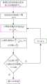
图3为本发明实施例中所述波束步进偏移器的设计流程图;Fig. 3 is the design flow chart of the beam stepping shifter described in the embodiment of the present invention;
图4为本发明实施例中所述天线与标准子阵级相控阵天线扫描到4°时的归一化仿真方向图对比图;4 is a comparison diagram of the normalized simulation pattern when the antenna described in the embodiment of the present invention and the standard sub-array-level phased array antenna are scanned to 4°;
图5为本发明实施例中所述天线与标准子阵级相控阵天线扫描到7.2°时的归一化仿真方向图对比图;5 is a comparison diagram of the normalized simulation pattern when the antenna described in the embodiment of the present invention and the standard sub-array-level phased array antenna are scanned to 7.2°;
图6为本发明实施例中所述天线在扫描角为0°~7.2°的扫描方向图;FIG. 6 is a scanning direction diagram of the antenna at a scanning angle of 0° to 7.2° in an embodiment of the present invention;
图7为本发明实施例中所述天线在扫描角为0°~8.5°的扫描方向图。FIG. 7 is a scanning direction diagram of the antenna at a scanning angle of 0° to 8.5° in an embodiment of the present invention.
具体实施方式Detailed ways
为使本发明实施例的目的、技术方案和优点更加清楚,下面将结合本发明实施例,对本发明实施例中的技术方案进行清楚、完整地描述。基于本发明中的实施例,本领域普通技术人员在没有作出创造性劳动前提下所获得的所有其他实施例,都属于本发明保护的范围。In order to make the purpose, technical solutions and advantages of the embodiments of the present invention clearer, the technical solutions in the embodiments of the present invention will be clearly and completely described below with reference to the embodiments of the present invention. Based on the embodiments of the present invention, all other embodiments obtained by those of ordinary skill in the art without creative efforts shall fall within the protection scope of the present invention.
实施例一Example 1
下面结合说明书附图以及具体的实施例对本发明的技术方案作进一步描述:The technical solutions of the present invention are further described below in conjunction with the accompanying drawings and specific embodiments:
如图1和图2所示,一种步进补偿低成本相控阵天线架构,包括n个天线子阵(1)、n个收发组件(2)、功分合成网络(5);每个所述的天线子阵(1)均包括一个波束步进偏移器(4)和m个基本辐射单元(3),每个所述的波束步进偏移器(4)均包括m个输出端,n个所述的波束步进偏移器(4)的输入端与n个所述的收发组件(2)的输出端连接,所述的波束步进偏移器(4)的m个输出端分别与m个基本辐射单元(3)的输入端连接,n个所述的收发组件(2)的输入端分别与功分合成网络(5)的对应的输出端连接;优选地m=n=8。As shown in FIG. 1 and FIG. 2, a step-compensated low-cost phased array antenna architecture includes n antenna sub-arrays (1), n transceiver components (2), and a power division and synthesis network (5); each Each of the antenna sub-arrays (1) includes a beam stepping shifter (4) and m basic radiation units (3), and each of the beam stepping shifters (4) includes m outputs end, the input ends of the n described beam stepping shifters (4) are connected with the output ends of the n described transceiver components (2), and the m beam stepping shifters (4) The output ends are respectively connected with the input ends of the m basic radiation units (3), and the input ends of the n described transceiver components (2) are respectively connected with the corresponding output ends of the power division and synthesis network (5); preferably m= n=8.
所述的收发组件(2)包含高位移相器,为天线空域扫描提供所需要的波束移相值;在实际应用中,预先利用公式
n个所述的天线子阵(1)等间距均匀排布,相邻的所述的天线子阵(1)的间距远大于λ;同一个天线子阵(1)内的m个基本辐射单元(3)等间距均匀排布,同一个天线子阵(1)内的相邻的基本辐射单元(3)间距不超过λ,λ为工作频率下电磁波在自由空间传播的波长。The n antenna sub-arrays (1) are evenly arranged at equal intervals, and the distance between the adjacent antenna sub-arrays (1) is much larger than λ; m basic radiating elements in the same antenna sub-array (1) (3) Evenly arranged at equal intervals, the distance between adjacent basic radiating elements (3) in the same antenna sub-array (1) does not exceed λ, where λ is the wavelength of electromagnetic waves propagating in free space at the operating frequency.
所述的波束步进偏移器(4)为离散偏移波束形成装置,实现子阵单元波束指向步进偏移;所述的波束步进偏移器(4)预设的波束偏离步进值为Ω,其值选择范围为:0°≤Ω≤θsmax,其中,θsmax为应用场景所需要的天线扫描的最大角度;所述波束步进偏移器(4)由低损耗低位移相组件构成;波束步进偏移器(4)具有低成本、低损耗的特点,波束步进偏移器4和收发组件2之间的射频电路以及功分合成网络5都采用低成本、低损耗材料经标准工艺加工而成。The beam stepping shifter (4) is a discrete shift beam forming device, which realizes the sub-array unit beam pointing step shift; the beam stepping shifter (4) presets the beam deviation step The value is Ω, and its value selection range is: 0°≤Ω≤θsmax , where θsmax is the maximum angle of antenna scanning required by the application scenario; the beam step shifter (4) is made of low loss and low displacement The beam stepping shifter (4) has the characteristics of low cost and low loss, and the radio frequency circuit between the
所述波束步进偏移器(4)通过电子控制器实现子阵级单元波束指向步进偏移;考虑到低成本的因素,所述的波束步进偏移器(4)的波束偏离步进值Ω应尽量大,步进波束的个数M应尽量少,但是由于步进波束的个数M越少,天线扫描性能越差,因此,需要综合考虑设计,使得天线成本最低同时满足各个扫描角度的性能要求。The beam stepping and shifting device (4) realizes the stepping and shifting of the beam pointing of the sub-array level unit through the electronic controller; considering the factor of low cost, the beam deviating step of the beam stepping and shifting device (4) The input value Ω should be as large as possible, and the number M of stepping beams should be as small as possible. However, since the number M of stepping beams is less, the scanning performance of the antenna will be worse. Therefore, it is necessary to comprehensively consider the design, so that the antenna cost is the lowest and meets the requirements of each Scanning angle performance requirements.
如图3所示,为本实施例中所述波束步进偏移器的设计流程图,图3中给出了天线方向图在要求的任意扫描角,主瓣比栅瓣高13dB的限制条件,具体的设计流程如下所示:As shown in Fig. 3, the design flow chart of the beam stepping shifter described in this embodiment is shown in Fig. 3. The restriction condition that the main lobe is 13dB higher than the grating lobe at the required arbitrary scanning angle of the antenna pattern is given in Fig. 3 , the specific design process is as follows:
a)根据应用场景确定所需要的天线扫描的最大角度θsmax;a) Determine the required maximum angle θsmax of antenna scanning according to the application scenario;
b)初始化步进波束的个数M=3;b) The number of initialized stepping beams M=3;
c)计算波束步进偏移初始值Ω;所述的Ω的计算公式为:c) Calculate the initial value Ω of the beam stepping offset; the calculation formula of the Ω is:

d)计算初始值下的扫描性能,当扫描角

e)判断初始态天线的扫描性能是否能满足方向图在要求的任意扫描角,主瓣比栅瓣高13dB的限制条件,如果不能,则将步进波束的个数M的值加2,重复步骤c)和步骤d),直到天线扫描性能满足要求为止;e) Determine whether the scanning performance of the initial antenna can meet the requirement that the pattern is at any required scanning angle, and the main lobe is 13dB higher than the grating lobe. If not, add 2 to the value of the number of stepping beams M, and repeat Step c) and step d), until the antenna scanning performance meets the requirements;
f)得到最终的步进波束的个数M和波束偏离步进值Ω。f) Obtain the final number M of stepped beams and the beam deviation step value Ω.
星间通讯时天线参数的具体设计Specific Design of Antenna Parameters for Inter-satellite Communication
为了降低子阵级相控阵的扫描增益损失,θsmax约束为子阵级相控阵大间距扫描时的极限扫描角度,即子阵级相控阵天线扫描到主瓣和栅瓣增益相等时所对应的角度;所述的θsmax的计算公式为:In order to reduce the scanning gain loss of the sub-array phased array, θsmax is constrained to be the limit scanning angle when the sub-array phased array scans with large spacing, that is, when the sub-array phased array antenna scans to the same gain of the main lobe and the grating lobe The corresponding angle; the calculation formula of the θsmax is:

其中,λ为工作频率下电磁波在自由空间传播的波长,d为相邻天线子阵(1)之间的间距,当d=4λ时,θsmax=7.2°,因此,所述波束步进偏移器4预设的波束偏离步进值Ω应满足0°≤Ω≤7.2°。Among them, λ is the wavelength of the electromagnetic wave propagating in free space at the working frequency, d is the spacing between adjacent antenna sub-arrays (1), when d=4λ, θsmax =7.2°, therefore, the beam step deviation is The preset beam deviation step value Ω of the
考虑到低成本低损耗,则波束步进偏移器4所设置的波束档位应尽量少,同时限制扫描范围内主瓣比栅瓣增益高13dB,综合以上两点,波束步进偏移器4的步进波束的个数M为3个(满足方向图在要求的任意扫描角,主瓣比栅瓣高13dB的限制条件),此时,根据公式(1)可得,波束偏离步进值Ω=4.8°,Ω0为所述波束步进偏移器4选择的波束档位,Ω0的可选值为-4.8°、0°或4.8°即Ω0∈(-4.8°、0°、4.8°),档位值Ω0根据波束最大指向角θ0确定,具体选择依据为:Considering the low cost and low loss, the beam position set by the

所述天线阵列在等幅馈电时,线阵天线的方向图函数可表示为:When the antenna array is fed with constant amplitude, the pattern function of the linear array antenna can be expressed as:

其中,n、m分别为天线子阵1的单元数和每个天线子阵1所包含基本辐射单元3的个数;λ为工作频率下电磁波在自由空间传播的波长;d为相邻天线子阵1之间的间距;θ0为天线波束最大指向;de为相邻基本辐射单元3之间的间距;p,q均为计数因子;优选地,相邻天线子阵1之间的间距d为4λ,相邻基本辐射单元3之间的间距de为λ/2。Among them, n and m are the number of elements of the antenna sub-array 1 and the number of
如图4所示,为本发明实施例中的线阵与标准子阵级相控阵天线扫描到4°时的仿真方向图对比图,此时实施例中天线的波束步进偏移器4选择Ω0=4.8°的档位。从图4中可以看出,当扫描角为4°时,实施例中线阵的增益比标准子阵级相控阵天线的增益高1dB。As shown in FIG. 4 , it is a comparison diagram of the simulation pattern when the linear array and the standard sub-array phased array antenna in the embodiment of the present invention are scanned to 4°. At this time, the
如图5所示,为本发明实施例中的线阵与标准子阵级相控阵天线扫描到7.2°时的仿真方向图对比图,此时实施例中天线的波束步进偏移器4选择Ω0=4.8°的档位。从图5中可以看出,当扫描角为7.2°时,实施例中线阵的增益比标准子阵级相控阵天线的增益高3.5dB。As shown in FIG. 5 , it is a comparison diagram of the simulation pattern when the linear array and the standard sub-array phased array antenna in the embodiment of the present invention are scanned to 7.2°. At this time, the
如图6所示,为本发明实施例中所述天线在扫描角为0°~7.2°的波束扫描方向图。从图6中可以看出,所述天线在0°~7.2°的波束扫描范围内,栅瓣比主瓣低不小于13dB,扫描到7.2°时增益仅下降约0.4dB。As shown in FIG. 6 , it is a beam scanning pattern of the antenna with a scanning angle of 0° to 7.2° in the embodiment of the present invention. It can be seen from Fig. 6 that in the beam scanning range of 0° to 7.2°, the grating lobe is not less than 13dB lower than the main lobe, and the gain only decreases by about 0.4dB when scanning to 7.2°.
星地通讯时天线参数的具体设计Specific Design of Antenna Parameters for Satellite-to-Earth Communication
考虑到通信卫星位于地球同步轨道时,天线波束覆盖整个地球边界的视场角约等于17°锥角空域,即天线必须具备±8.5°的扫描能力才能实现完全覆盖,而8单元标准子阵级相控阵极限扫描角度仅为±7.2°,因此,考虑引入波束步进偏移器的天线架构,实现同步轨道通信卫星波束全覆盖。Considering that when the communication satellite is located in the geosynchronous orbit, the field of view of the antenna beam covering the entire earth boundary is approximately equal to the 17° cone angle airspace, that is, the antenna must have a scanning capability of ±8.5° to achieve complete coverage, while the 8-element standard subarray level The limited scanning angle of the phased array is only ±7.2°. Therefore, the antenna architecture of introducing a beam step shifter is considered to achieve full coverage of the synchronous orbit communication satellite beam.
为了实现±8.5°的波束覆盖,所述波束步进偏移器4预设的波束偏离步进值应满足0°≤Ω≤8.5°。同时限制扫描范围内主瓣比栅瓣增益高13dB,综合以上两点,波束步进偏移器4的波束偏移步进Ω=3.4°,步进波束的个数为5个(满足方向图在要求的任意扫描角,主瓣比栅瓣高13dB的限制条件),档位设置为Ω0∈(-6.8°、-3.4°、0°、3.4°、6.8°),档位值根据波束最大指向角θ0确定,具体选择依据为:In order to achieve a beam coverage of ±8.5°, the preset beam deviation step value of the

如图7所示,为本发明实施例中所述天线在扫描角为0°~8.5°的波束扫描方向图。从图7中可以看出,所述天线在0°~8.5°的波束扫描范围内,栅瓣比主瓣低不小于13dB,扫描到8.5°时增益仅下降约0.2dB。As shown in FIG. 7 , it is a beam scanning pattern of the antenna with a scanning angle of 0° to 8.5° in the embodiment of the present invention. It can be seen from Fig. 7 that in the beam scanning range of 0° to 8.5°, the grating lobe of the antenna is not less than 13dB lower than the main lobe, and the gain only decreases by about 0.2dB when scanning to 8.5°.
以上实施例仅用以说明本发明的技术方案,而非对其限制;尽管参照前述实施例对本发明进行了详细的说明,本领域的普通技术人员应当理解:其依然可以对前述各实施例所记载的技术方案进行修改,或者对其中部分技术特征进行等同替换;而这些修改或者替换,并不使相应技术方案的本质脱离本发明各实施例技术方案的精神和范围。The above embodiments are only used to illustrate the technical solutions of the present invention, but not to limit them; although the present invention has been described in detail with reference to the foregoing embodiments, those of ordinary skill in the art should understand that: The recorded technical solutions are modified, or some technical features thereof are equivalently replaced; and these modifications or replacements do not make the essence of the corresponding technical solutions deviate from the spirit and scope of the technical solutions of the embodiments of the present invention.
Claims (10)
Translated fromChinese


Priority Applications (1)
| Application Number | Priority Date | Filing Date | Title |
|---|---|---|---|
| CN202010917703.6ACN112072309B (en) | 2020-09-03 | 2020-09-03 | A Low-cost Phased Array Antenna Architecture with Step Compensation and Its Design Method |
Applications Claiming Priority (1)
| Application Number | Priority Date | Filing Date | Title |
|---|---|---|---|
| CN202010917703.6ACN112072309B (en) | 2020-09-03 | 2020-09-03 | A Low-cost Phased Array Antenna Architecture with Step Compensation and Its Design Method |
Publications (2)
| Publication Number | Publication Date |
|---|---|
| CN112072309Atrue CN112072309A (en) | 2020-12-11 |
| CN112072309B CN112072309B (en) | 2023-02-28 |
Family
ID=73665729
Family Applications (1)
| Application Number | Title | Priority Date | Filing Date |
|---|---|---|---|
| CN202010917703.6AActiveCN112072309B (en) | 2020-09-03 | 2020-09-03 | A Low-cost Phased Array Antenna Architecture with Step Compensation and Its Design Method |
Country Status (1)
| Country | Link |
|---|---|
| CN (1) | CN112072309B (en) |
Cited By (2)
| Publication number | Priority date | Publication date | Assignee | Title |
|---|---|---|---|---|
| CN113922015A (en)* | 2021-10-13 | 2022-01-11 | 中国人民解放军32802部队 | Filtering reconfigurable wave beam forming network with continuously adjustable frequency and scanning angle |
| CN116505266A (en)* | 2023-06-28 | 2023-07-28 | 成都迅翼卫通科技有限公司 | Phased array antenna full airspace star searching method and device |
Citations (25)
| Publication number | Priority date | Publication date | Assignee | Title |
|---|---|---|---|---|
| US4276551A (en)* | 1979-06-01 | 1981-06-30 | Hughes Aircraft Company | Electronically scanned antenna |
| JPH05110328A (en)* | 1991-06-12 | 1993-04-30 | Toyo Commun Equip Co Ltd | Beam phase shift compensation system for phased array antenna |
| US5414433A (en)* | 1994-02-16 | 1995-05-09 | Raytheon Company | Phased array radar antenna with two-stage time delay units |
| FR2784803A1 (en)* | 1998-10-19 | 2000-04-21 | Ni Elektromekhanichesky I | Phased array antenna with electronic beam steering, especially for a missile launching air defense radar, has group of identical sub-arrays each with individual exciters and controlled phase shifters |
| CN101764285A (en)* | 2010-01-27 | 2010-06-30 | 北京握奇数据系统有限公司 | Method for controlling antenna wave beam to point to moving vehicle, antenna and no-stop parking charge system |
| CN101936756A (en)* | 2010-08-31 | 2011-01-05 | 华南理工大学 | A multi-frequency phased array ultrasonic Doppler flow detection system and method |
| CN103207395A (en)* | 2013-03-26 | 2013-07-17 | 南京理工大学 | Driving anti-collision radar device for automobile |
| CN104122535A (en)* | 2014-07-17 | 2014-10-29 | 中国电子科技集团公司第二十研究所 | True time delay device based phased-array antenna broadband anti-interference method |
| CN104133194A (en)* | 2014-07-17 | 2014-11-05 | 中国电子科技集团公司第二十研究所 | Broadband phased array based on true time delay technology |
| CN105024143A (en)* | 2015-08-06 | 2015-11-04 | 中国电子科技集团公司第三十八研究所 | Chip-type Ka-frequency band wide-angle scanning satellite communication antenna |
| WO2016106631A1 (en)* | 2014-12-31 | 2016-07-07 | 华为技术有限公司 | Antenna system and beam control method |
| CN105785328A (en)* | 2016-03-15 | 2016-07-20 | 西安电子科技大学 | Subarray-division-based FDA distance-angle decoupling wave beam formation method |
| CN105914476A (en)* | 2016-05-20 | 2016-08-31 | 中国电子科技集团公司第十研究所 | Ka-band tilt-structure active phased array antenna |
| CN106159465A (en)* | 2016-09-05 | 2016-11-23 | 广东博纬通信科技有限公司 | Wideband five beam array antenna |
| CN106252886A (en)* | 2016-08-29 | 2016-12-21 | 中国人民解放军火箭军工程大学 | The multiple submatrixes antenna beam changing method of minimum deviation is pointed to based on antenna beam |
| CN106299726A (en)* | 2016-11-07 | 2017-01-04 | 中国电子科技集团公司第二十研究所 | A kind of implementation method of phased array uniform speed scanning based on arcsine clock |
| CN106324602A (en)* | 2016-07-29 | 2017-01-11 | 中国科学院声学研究所 | MIMO sonar system |
| JP2017146156A (en)* | 2016-02-16 | 2017-08-24 | 株式会社東芝 | Radar equipment |
| CN107329134A (en)* | 2017-06-29 | 2017-11-07 | 电子科技大学 | A kind of ripple control battle array ULTRA-WIDEBAND RADAR aerial array that waveform control is fed based on array element |
| CN108008388A (en)* | 2017-11-27 | 2018-05-08 | 上海航天测控通信研究所 | A kind of spaceborne phased array SAR load beam-steering methods |
| CN108061892A (en)* | 2017-12-05 | 2018-05-22 | 上海无线电设备研究所 | A kind of spaceborne full spatial domain anticollision warning system |
| CN109586035A (en)* | 2018-10-16 | 2019-04-05 | 江苏万邦微电子有限公司 | A kind of phase array antenna beam control system |
| CN109687124A (en)* | 2018-12-05 | 2019-04-26 | 东南大学 | A kind of Millimeter Wave Phased Array Antenna device and its implementation for mobile terminal |
| CN110376552A (en)* | 2019-09-03 | 2019-10-25 | 上海无线电设备研究所 | A kind of low cost annular phased-array radar system and working method |
| CN110531333A (en)* | 2019-08-22 | 2019-12-03 | 北京理工大学 | A kind of wideband radar aperture transition effect self-adapting compensation method |
- 2020
- 2020-09-03CNCN202010917703.6Apatent/CN112072309B/enactiveActive
Patent Citations (25)
| Publication number | Priority date | Publication date | Assignee | Title |
|---|---|---|---|---|
| US4276551A (en)* | 1979-06-01 | 1981-06-30 | Hughes Aircraft Company | Electronically scanned antenna |
| JPH05110328A (en)* | 1991-06-12 | 1993-04-30 | Toyo Commun Equip Co Ltd | Beam phase shift compensation system for phased array antenna |
| US5414433A (en)* | 1994-02-16 | 1995-05-09 | Raytheon Company | Phased array radar antenna with two-stage time delay units |
| FR2784803A1 (en)* | 1998-10-19 | 2000-04-21 | Ni Elektromekhanichesky I | Phased array antenna with electronic beam steering, especially for a missile launching air defense radar, has group of identical sub-arrays each with individual exciters and controlled phase shifters |
| CN101764285A (en)* | 2010-01-27 | 2010-06-30 | 北京握奇数据系统有限公司 | Method for controlling antenna wave beam to point to moving vehicle, antenna and no-stop parking charge system |
| CN101936756A (en)* | 2010-08-31 | 2011-01-05 | 华南理工大学 | A multi-frequency phased array ultrasonic Doppler flow detection system and method |
| CN103207395A (en)* | 2013-03-26 | 2013-07-17 | 南京理工大学 | Driving anti-collision radar device for automobile |
| CN104122535A (en)* | 2014-07-17 | 2014-10-29 | 中国电子科技集团公司第二十研究所 | True time delay device based phased-array antenna broadband anti-interference method |
| CN104133194A (en)* | 2014-07-17 | 2014-11-05 | 中国电子科技集团公司第二十研究所 | Broadband phased array based on true time delay technology |
| WO2016106631A1 (en)* | 2014-12-31 | 2016-07-07 | 华为技术有限公司 | Antenna system and beam control method |
| CN105024143A (en)* | 2015-08-06 | 2015-11-04 | 中国电子科技集团公司第三十八研究所 | Chip-type Ka-frequency band wide-angle scanning satellite communication antenna |
| JP2017146156A (en)* | 2016-02-16 | 2017-08-24 | 株式会社東芝 | Radar equipment |
| CN105785328A (en)* | 2016-03-15 | 2016-07-20 | 西安电子科技大学 | Subarray-division-based FDA distance-angle decoupling wave beam formation method |
| CN105914476A (en)* | 2016-05-20 | 2016-08-31 | 中国电子科技集团公司第十研究所 | Ka-band tilt-structure active phased array antenna |
| CN106324602A (en)* | 2016-07-29 | 2017-01-11 | 中国科学院声学研究所 | MIMO sonar system |
| CN106252886A (en)* | 2016-08-29 | 2016-12-21 | 中国人民解放军火箭军工程大学 | The multiple submatrixes antenna beam changing method of minimum deviation is pointed to based on antenna beam |
| CN106159465A (en)* | 2016-09-05 | 2016-11-23 | 广东博纬通信科技有限公司 | Wideband five beam array antenna |
| CN106299726A (en)* | 2016-11-07 | 2017-01-04 | 中国电子科技集团公司第二十研究所 | A kind of implementation method of phased array uniform speed scanning based on arcsine clock |
| CN107329134A (en)* | 2017-06-29 | 2017-11-07 | 电子科技大学 | A kind of ripple control battle array ULTRA-WIDEBAND RADAR aerial array that waveform control is fed based on array element |
| CN108008388A (en)* | 2017-11-27 | 2018-05-08 | 上海航天测控通信研究所 | A kind of spaceborne phased array SAR load beam-steering methods |
| CN108061892A (en)* | 2017-12-05 | 2018-05-22 | 上海无线电设备研究所 | A kind of spaceborne full spatial domain anticollision warning system |
| CN109586035A (en)* | 2018-10-16 | 2019-04-05 | 江苏万邦微电子有限公司 | A kind of phase array antenna beam control system |
| CN109687124A (en)* | 2018-12-05 | 2019-04-26 | 东南大学 | A kind of Millimeter Wave Phased Array Antenna device and its implementation for mobile terminal |
| CN110531333A (en)* | 2019-08-22 | 2019-12-03 | 北京理工大学 | A kind of wideband radar aperture transition effect self-adapting compensation method |
| CN110376552A (en)* | 2019-09-03 | 2019-10-25 | 上海无线电设备研究所 | A kind of low cost annular phased-array radar system and working method |
Non-Patent Citations (5)
| Title |
|---|
| WEI WANG: "Transmit Signal Designs for Spatial Modulation With Analog Phase Shifters", 《IEEE ACCESS》* |
| 周家喜: "一种S和Ka双频段相控阵卫星动中通天线设计", 《电磁场与微波》* |
| 斯扬: "相控阵天线试验子阵波束指向性能分析", 《航天器工程》* |
| 苏君: "相控阵天线全光移相网络", 《光通信技术》* |
| 鲁加国等: "星载SAR相控阵天线栅瓣抑制技术", 《微波学报》* |
Cited By (3)
| Publication number | Priority date | Publication date | Assignee | Title |
|---|---|---|---|---|
| CN113922015A (en)* | 2021-10-13 | 2022-01-11 | 中国人民解放军32802部队 | Filtering reconfigurable wave beam forming network with continuously adjustable frequency and scanning angle |
| CN116505266A (en)* | 2023-06-28 | 2023-07-28 | 成都迅翼卫通科技有限公司 | Phased array antenna full airspace star searching method and device |
| CN116505266B (en)* | 2023-06-28 | 2023-09-15 | 成都迅翼卫通科技有限公司 | Phased array antenna full airspace star searching method and device |
Also Published As
| Publication number | Publication date |
|---|---|
| CN112072309B (en) | 2023-02-28 |
Similar Documents
| Publication | Publication Date | Title |
|---|---|---|
| TWI806070B (en) | System and method for a multi-beam beamforming front-end architecture for wireless transceivers | |
| JP7224174B2 (en) | Electronic device and radar control method | |
| US11700056B2 (en) | Phased array antenna for use with low earth orbit satellite constellations | |
| US11742586B2 (en) | Lens-enhanced communication device | |
| CN102110884B (en) | Active phased array antenna adopting passive loading way to control sidelobe level | |
| US8604989B1 (en) | Steerable antenna | |
| CN111048911A (en) | Phased array antenna capable of realizing random polarization switching | |
| CN112072309B (en) | A Low-cost Phased Array Antenna Architecture with Step Compensation and Its Design Method | |
| US5124712A (en) | Method of forming the radiation pattern of a high efficiency active antenna for an electronically-scanned radar, and an antenna implementing the method | |
| Russell | Future of RF technology and radars | |
| CN117832880A (en) | A large-spacing antenna array and debugging method thereof | |
| CN112366459A (en) | Integrated active multi-beam Rotman lens antenna | |
| US11217897B1 (en) | Antenna system and method with a hybrid beamformer architecture | |
| US10741917B2 (en) | Power division in antenna systems for millimeter wave applications | |
| CN210744162U (en) | Phased array antenna capable of realizing random polarization switching | |
| Jiaguo et al. | Active phased array antenna based on DDS | |
| JP2024533063A (en) | Calculating the Variance of Phased Array Beamforming Parameters | |
| Kira et al. | New design approach to multiple-beam forming network for beam-steerable phased array antennas | |
| CN119199760B (en) | A phased array radar jammer system with multi-beam reception and narrow beam transmission | |
| Georgiadis et al. | Patents on reconfigurable reflectarray antennas | |
| CN115102584B (en) | Array beam forming device for realizing broadband low side lobe | |
| RU2754653C1 (en) | Method for generating a radiation pattern and an antenna array for its implementation | |
| Djerafi et al. | Substrate integrated waveguide feeding network for for angular-limited scan arrays with overlapped subarrays | |
| KR20250018707A (en) | Metamaterial Flat Lens-Combined Pointing Angle-Control by Switching Electromagnetic-Wave Source(PACbyEMSS) for Radr and Communication Beamforming Antennas Doing Away With Chip-Type Active Phase Shifters | |
| Dasan et al. | Digital Implementation of Beam Squint Mitigation for Wide Band Active Phased Radars |
Legal Events
| Date | Code | Title | Description |
|---|---|---|---|
| PB01 | Publication | ||
| PB01 | Publication | ||
| SE01 | Entry into force of request for substantive examination | ||
| SE01 | Entry into force of request for substantive examination | ||
| GR01 | Patent grant | ||
| GR01 | Patent grant |