CN112068645A - Adapter board, connecting device and electronic device thereof - Google Patents
Adapter board, connecting device and electronic device thereofDownload PDFInfo
- Publication number
- CN112068645A CN112068645ACN201910498008.8ACN201910498008ACN112068645ACN 112068645 ACN112068645 ACN 112068645ACN 201910498008 ACN201910498008 ACN 201910498008ACN 112068645 ACN112068645 ACN 112068645A
- Authority
- CN
- China
- Prior art keywords
- connector
- solid state
- state disk
- adapter
- control module
- Prior art date
- Legal status (The legal status is an assumption and is not a legal conclusion. Google has not performed a legal analysis and makes no representation as to the accuracy of the status listed.)
- Pending
Links
Images
Classifications
- G—PHYSICS
- G06—COMPUTING OR CALCULATING; COUNTING
- G06F—ELECTRIC DIGITAL DATA PROCESSING
- G06F1/00—Details not covered by groups G06F3/00 - G06F13/00 and G06F21/00
- G06F1/16—Constructional details or arrangements
- G06F1/18—Packaging or power distribution
- G06F1/183—Internal mounting support structures, e.g. for printed circuit boards, internal connecting means
Landscapes
- Engineering & Computer Science (AREA)
- Theoretical Computer Science (AREA)
- Computer Hardware Design (AREA)
- Power Engineering (AREA)
- Human Computer Interaction (AREA)
- Physics & Mathematics (AREA)
- General Engineering & Computer Science (AREA)
- General Physics & Mathematics (AREA)
- Details Of Connecting Devices For Male And Female Coupling (AREA)
Abstract
Description
Translated fromChinese技术领域technical field
本发明涉及一种转接板、连接装置及其电子装置。The invention relates to an adapter board, a connecting device and an electronic device thereof.
背景技术Background technique
随着服务器和电脑产品的发展日新月异,需要支持各种HDD(Hard Disk Drive,硬盘驱动)驱动器,M.2接口SSD(固态硬盘)是一种常用的配置。目前开始使用的平台服务器和工作站,需要支持PCIE 4.0,而传统的M.2模块,仅支持PCIE 3.0,另外,传统的M.2模块一般包括热插拔背板以及转接板,其通常不能支持GEN4信号,同时,其还需要多个转换板与接触板组合实现信号转接,组装过程复杂,且信号传输质量不佳。With the rapid development of server and computer products, it is necessary to support various HDD (Hard Disk Drive, hard disk drive) drives, and M.2 interface SSD (Solid State Drive) is a commonly used configuration. The platform servers and workstations currently in use need to support PCIE 4.0, while traditional M.2 modules only support PCIE 3.0. In addition, traditional M.2 modules generally include hot-swappable backplanes and adapter boards, which usually cannot It supports GEN4 signal, and at the same time, it also requires a combination of multiple conversion boards and contact boards to realize signal transfer, the assembly process is complicated, and the signal transmission quality is poor.
发明内容SUMMARY OF THE INVENTION
针对上述问题,有必要提供一种组装简单且信号传输质量较佳的电子装置转接板、连接装置及其电子装置。In view of the above problems, it is necessary to provide an electronic device adapter board, a connecting device and an electronic device thereof with simple assembly and better signal transmission quality.
一种转接板,用于实现中央处理器与固态硬盘之间的连接,所述转接板包括依次电性连接的第一连接器、控制模块以及第二连接器,所述第一连接器用于连接所述中央处理器;所述第二连接器,用于连接所述固态硬盘;所述控制模块用于对所述固态硬盘进行识别及控制;所述转接板支持热插拔、信号转换以及接触功能。An adapter board is used to realize the connection between a central processing unit and a solid state hard disk. The adapter board includes a first connector, a control module and a second connector that are electrically connected in sequence, and the first connector is used for for connecting to the central processing unit; the second connector for connecting the solid-state hard disk; the control module for identifying and controlling the solid-state hard disk; the adapter board supports hot swap, signal Conversion and contact functions.
进一步地,所述第一连接器为高密度连接器,且支持PCIE(peripheral componentinterconnect express,高速串行计算机扩展总线标准)第四代八通道卡GEN4×8信号传输。Further, the first connector is a high-density connector, and supports PCIE (peripheral component interconnect express, high-speed serial computer expansion bus standard) fourth-generation eight-channel card GEN4×8 signal transmission.
进一步地,所述第二连接器为高密度连接器,且支持PCIE第四代四通道卡GEN4×4信号传输。Further, the second connector is a high-density connector, and supports PCIE fourth-generation four-channel card GEN4×4 signal transmission.
进一步地,所述控制模块识别所述固态硬盘与所述第二连接器连接状态,并在所述固态硬盘与所述第二连接器连接后,控制所述中央处理器与所述固态硬盘之间进行数据传输。Further, the control module identifies the connection state between the solid state drive and the second connector, and controls the connection between the central processing unit and the solid state drive after the solid state drive is connected to the second connector. data transfer between.
进一步地,所述转接板包括与所示控制模块电性相连的显示模块,用于显示所述固态硬盘与所述第二连接器的连接状态。Further, the adapter board includes a display module that is electrically connected to the control module, and is used to display the connection state of the solid state drive and the second connector.
一种连接装置,包括依次电性连接的中央处理器、转接板以及固态硬盘,所述转接板为上述的转接板。A connecting device includes a central processing unit, an adapter board, and a solid-state hard disk that are electrically connected in sequence, and the adapter board is the above-mentioned adapter board.
进一步地,所述连接装置还包括第三连接器,所述第三连接器用于连接所述中央处理器与所述第一连接器。Further, the connection device further includes a third connector for connecting the central processing unit and the first connector.
进一步地,所述第三连接器为高密度连接器,且支持PCIE GEN4×8信号传输。Further, the third connector is a high-density connector and supports PCIE GEN4×8 signal transmission.
进一步地,所述连接装置包括两个第三连接器、两个转接板以及四个固态硬盘,所述中央处理器通过所述两个第三连接器分别连接至所述两个转接板的第一连接器,每一个所述转接板的第二连接器分别连接一个固态硬盘。Further, the connection device includes two third connectors, two adapter boards and four solid-state drives, and the central processing unit is connected to the two adapter boards through the two third connectors, respectively the first connector, and the second connector of each adapter board is respectively connected to a solid-state hard disk.
一种电子装置,包括上述连接装置,所述电子装置为电脑、服务器或者工作站。An electronic device, comprising the above-mentioned connecting device, the electronic device is a computer, a server or a workstation.
上述转接板集成热插拔、信号转换以及接触功能,且可支持PCIE 4.0GEN4信号传输,使得所述CPU与所述固态硬盘之间无需设置多个转换板或者接触板,组装简单且信号传输质量较佳此外,每一个所述转接板可以实现两个固态硬盘与所述CPU之间的转接,因此,可降低成本。The above-mentioned adapter board integrates hot-plug, signal conversion and contact functions, and can support PCIE 4.0GEN4 signal transmission, so that there is no need to set up multiple conversion boards or contact boards between the CPU and the solid-state hard disk, and the assembly is simple and the signal transmission. Better quality In addition, each of the adapter boards can realize the adapter between two solid-state drives and the CPU, so the cost can be reduced.
附图说明Description of drawings
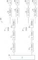
图1为本发明较佳实施例的连接装置的功能模块图。FIG. 1 is a functional block diagram of a connection device according to a preferred embodiment of the present invention.
主要元件符号说明Description of main component symbols
连接装置 100
转接板 10
第一连接器 11
控制模块 13
第二连接器 15
CPU 30
第三连接器 31
SSD 50SSD 50
如下具体实施方式将结合上述附图进一步说明本发明。The following specific embodiments will further illustrate the present invention in conjunction with the above drawings.
具体实施方式Detailed ways
下面将结合本发明实施例中的附图,对本发明实施例中的技术方案进行清楚、完整地描述,显然,所描述的实施例是本发明一部分实施例,而不是全部的实施例。The technical solutions in the embodiments of the present invention will be clearly and completely described below with reference to the accompanying drawings in the embodiments of the present invention. Obviously, the described embodiments are part of the embodiments of the present invention, but not all of the embodiments.
为了使本发明的目的、技术方案及优点更加清楚明白,以下将会结合附图及实施方式,以对本发明中的转接板、连接装置及其电子装置作进一步详细的描述及相关说明。In order to make the objectives, technical solutions and advantages of the present invention clearer, the following will further describe and describe the adapter board, the connecting device and the electronic device thereof in detail in conjunction with the accompanying drawings and embodiments.
请参考图1,本发明较佳实施方式提供一种连接装置100,所述连接装置100适用于电脑、服务器、工作站等电子装置。Referring to FIG. 1 , a preferred embodiment of the present invention provides a connecting
所述连接装置100包括转接板10、以及通过所述转接板10建立连接并进行信号传输的CPU(central processing unit,中央处理器)30以及SSD(solid state disk,固态硬盘)50。The
所述转接板10包括依次电性连接的第一连接器11、控制模块13以及第二连接器15,所述第一连接器11用于连接所述CPU 30。所述第二连接器15用于连接所述SSD 50。所述控制模块13用于对所述SSD 50进行识别及控制。所述转接板10支持热插拔、信号转换以及接触功能。The
在本较佳实施例中,所述第一连接器11为高密度连接器,且支持PCIE(peripheralcomponent interconnect express,高速串行计算机扩展总线标准)第四代八通道卡GEN4×8信号传输。In this preferred embodiment, the
所述控制模块13识别所述SSD 50与所述第二连接器15连接状态,并在所述SSD 50与所述第二连接器15连接后,控制所述CPU30与所述SSD 50之间进行数据传输。The
可以理解,所述转接板10还包括与所示控制模块13电性相连的显示模块(图未示),例如,LED,所述显示模块用于显示所述SSD50与所述第二连接器15的连接状态。It can be understood that the
在本较佳实施例中,所述第二连接器15为高密度连接器,且支持PCIE第四代四通道卡GEN4×4信号传输。In this preferred embodiment, the
可以理解,所述连接装置100还包括第三连接器31,所述第三连接器31用于连接所述CPU 30与所述第一连接器11。所述第三连接器31为高密度连接器,且支持PCIE 4.0GEN4×8信号传输。It can be understood that the
在本较佳实施例中,所述SSD50为M.2固态硬盘。In this preferred embodiment, the SSD50 is an M.2 solid state drive.
在本较佳实施例中,所述连接装置100包括两个第三连接器31、两个转接板10以及四个SSD 50。所述CPU 30通过所述两个第三连接器31分别连接至所述两个转接板10的第一连接器11,每一个所述转接板10的第二连接器15分别连接一个SSD 50。因此,每一个所述转接板10可以实现两个SSD50与所述CPU 30之间的转接。所述每一个转接板10以及与其相连的两个SSD50可装设于承载装置(图未示),所述承载装置可装设于硬盘容纳盒(图未示)。In this preferred embodiment, the
上述转接板10集成热插拔、信号转换以及接触功能,且可支持PCIE 4.0GEN4信号传输,使得所述CPU 30与所述SSD 50之间无需设置多个转换板或者接触板,组装简单且信号传输质量较佳,此外,每一个所述转接板10可以实现两个SSD 50与所述CPU 30之间的转接,因此,可降低成本。The above-mentioned
最后应说明的是,以上实施例仅用以说明本发明的技术方案而非限制,尽管参照较佳实施例对本发明进行了详细说明。Finally, it should be noted that the above embodiments are only used to illustrate the technical solutions of the present invention and not to limit them, although the present invention has been described in detail with reference to the preferred embodiments.
本领域的普通技术人员应当理解,可以对本发明的技术方案进行修改或等同替换,而不脱离本发明技术方案的精神和范围。It should be understood by those skilled in the art that the technical solutions of the present invention may be modified or equivalently replaced without departing from the spirit and scope of the technical solutions of the present invention.
并且,基于本发明中的实施例,本领域普通技术人员在没有做出创造性劳动前提下所获得的所有其他实施例,都将属于本发明保护的范围。In addition, based on the embodiments of the present invention, all other embodiments obtained by those of ordinary skill in the art without creative efforts will fall within the protection scope of the present invention.
Claims (10)
Priority Applications (1)
| Application Number | Priority Date | Filing Date | Title |
|---|---|---|---|
| CN201910498008.8ACN112068645A (en) | 2019-06-10 | 2019-06-10 | Adapter board, connecting device and electronic device thereof |
Applications Claiming Priority (1)
| Application Number | Priority Date | Filing Date | Title |
|---|---|---|---|
| CN201910498008.8ACN112068645A (en) | 2019-06-10 | 2019-06-10 | Adapter board, connecting device and electronic device thereof |
Publications (1)
| Publication Number | Publication Date |
|---|---|
| CN112068645Atrue CN112068645A (en) | 2020-12-11 |
Family
ID=73658363
Family Applications (1)
| Application Number | Title | Priority Date | Filing Date |
|---|---|---|---|
| CN201910498008.8APendingCN112068645A (en) | 2019-06-10 | 2019-06-10 | Adapter board, connecting device and electronic device thereof |
Country Status (1)
| Country | Link |
|---|---|
| CN (1) | CN112068645A (en) |
Cited By (1)
| Publication number | Priority date | Publication date | Assignee | Title |
|---|---|---|---|---|
| TWI773463B (en)* | 2021-07-29 | 2022-08-01 | 緯穎科技服務股份有限公司 | Solid state disk device |
- 2019
- 2019-06-10CNCN201910498008.8Apatent/CN112068645A/enactivePending
Cited By (2)
| Publication number | Priority date | Publication date | Assignee | Title |
|---|---|---|---|---|
| TWI773463B (en)* | 2021-07-29 | 2022-08-01 | 緯穎科技服務股份有限公司 | Solid state disk device |
| US11797226B2 (en) | 2021-07-29 | 2023-10-24 | Wiwynn Corporation | Solid state disk device |
Similar Documents
| Publication | Publication Date | Title |
|---|---|---|
| US11596073B2 (en) | Electronic equipment that provides multi-function slots | |
| CN206249296U (en) | A kind of dual control storage server | |
| JP3304292B2 (en) | Automatic detection device for detecting attachment or identification of an external device, information processing device, and external device | |
| US7490176B2 (en) | Serial attached SCSI backplane and detection system thereof | |
| CN107992438A (en) | A kind of server and in server flexible configuration PCIe topologys method | |
| US7000037B2 (en) | Large array of mass data storage devices connected to a computer by a serial link | |
| US8064205B2 (en) | Storage devices including different sets of contacts | |
| CN108090014A (en) | The storage IO casees system and its design method of a kind of compatible NVMe | |
| TWI231414B (en) | Topology for 66 MHz PCI bus riser card system | |
| CN110069436A (en) | Hot plug control circuit and associated storage servers system | |
| CN103246314A (en) | Mainboard with expansion connector | |
| CN213545261U (en) | Server mainboard based on dual-path processor | |
| US20060264085A1 (en) | Method and apparatus for coupling a plurality of cards to an information handling system | |
| CN115904024A (en) | A multi-mode hard disk backplane structure, method and server | |
| CN112068645A (en) | Adapter board, connecting device and electronic device thereof | |
| US11163343B1 (en) | Flexible power supply unit (PSU) bay | |
| US12072827B2 (en) | Scaling midplane bandwidth between storage processors via network devices | |
| CN205003580U (en) | Embedded industry mainboard | |
| CN107357744A (en) | It is a kind of to support HDD and the M.2 method and structure of storage medium self-identifying | |
| CN211149439U (en) | OCP keysets and support NVME's OCP switching system | |
| CN114020668B (en) | Signal processing system, mainboard and server | |
| CN111737174A (en) | A hard disk backplane compatible with Tri-mode RAID function and its design method | |
| TWI852755B (en) | Hot plugging control system | |
| CN211669632U (en) | Electronic equipment and operation extension module | |
| TW201622520A (en) | Sever |
Legal Events
| Date | Code | Title | Description |
|---|---|---|---|
| PB01 | Publication | ||
| PB01 | Publication | ||
| WD01 | Invention patent application deemed withdrawn after publication | ||
| WD01 | Invention patent application deemed withdrawn after publication | Application publication date:20201211 |