CN112060682A - Lifting handle belt transferring, installing and leveling device of lifting handle installing machine and using method thereof - Google Patents
Lifting handle belt transferring, installing and leveling device of lifting handle installing machine and using method thereofDownload PDFInfo
- Publication number
- CN112060682A CN112060682ACN202010986297.9ACN202010986297ACN112060682ACN 112060682 ACN112060682 ACN 112060682ACN 202010986297 ACN202010986297 ACN 202010986297ACN 112060682 ACN112060682 ACN 112060682A
- Authority
- CN
- China
- Prior art keywords
- handle
- arc
- belt
- handle belt
- installation
- Prior art date
- Legal status (The legal status is an assumption and is not a legal conclusion. Google has not performed a legal analysis and makes no representation as to the accuracy of the status listed.)
- Granted
Links
- 238000000034methodMethods0.000titleclaimsdescription25
- 238000009434installationMethods0.000claimsabstractdescription130
- 230000007246mechanismEffects0.000claimsabstractdescription113
- 239000011111cardboardSubstances0.000claimsdescription42
- 238000009423ventilationMethods0.000claimsdescription42
- 238000009499grossingMethods0.000claimsdescription35
- 230000006835compressionEffects0.000claimsdescription8
- 238000007906compressionMethods0.000claimsdescription8
- 238000005520cutting processMethods0.000description46
- 238000009826distributionMethods0.000description28
- 238000003825pressingMethods0.000description23
- 230000033001locomotionEffects0.000description22
- 239000000463materialSubstances0.000description11
- 238000010586diagramMethods0.000description8
- 238000011900installation processMethods0.000description5
- 239000004745nonwoven fabricSubstances0.000description5
- 230000005540biological transmissionEffects0.000description4
- 239000011087paperboardSubstances0.000description4
- 230000003068static effectEffects0.000description4
- 238000011144upstream manufacturingMethods0.000description4
- 238000001125extrusionMethods0.000description3
- 238000004806packaging method and processMethods0.000description3
- 239000004033plasticSubstances0.000description3
- 238000003860storageMethods0.000description3
- 239000000853adhesiveSubstances0.000description2
- 230000001070adhesive effectEffects0.000description2
- 239000003292glueSubstances0.000description2
- 238000004519manufacturing processMethods0.000description2
- 238000005096rolling processMethods0.000description2
- 230000000712assemblyEffects0.000description1
- 238000000429assemblyMethods0.000description1
- 230000007613environmental effectEffects0.000description1
- 239000008187granular materialSubstances0.000description1
- 230000005484gravityEffects0.000description1
- 239000000123paperSubstances0.000description1
- 238000004064recyclingMethods0.000description1
- 230000029058respiratory gaseous exchangeEffects0.000description1
- 238000001179sorption measurementMethods0.000description1
- 230000007723transport mechanismEffects0.000description1
Images


Classifications
- B—PERFORMING OPERATIONS; TRANSPORTING
- B31—MAKING ARTICLES OF PAPER, CARDBOARD OR MATERIAL WORKED IN A MANNER ANALOGOUS TO PAPER; WORKING PAPER, CARDBOARD OR MATERIAL WORKED IN A MANNER ANALOGOUS TO PAPER
- B31B—MAKING CONTAINERS OF PAPER, CARDBOARD OR MATERIAL WORKED IN A MANNER ANALOGOUS TO PAPER
- B31B50/00—Making rigid or semi-rigid containers, e.g. boxes or cartons
- B31B50/74—Auxiliary operations
- B31B50/81—Forming or attaching accessories, e.g. opening devices, closures or tear strings
- B31B50/86—Forming integral handles; Attaching separate handles
- B31B50/87—Fitting separate handles on boxes, e.g. on drinking cups
- B—PERFORMING OPERATIONS; TRANSPORTING
- B31—MAKING ARTICLES OF PAPER, CARDBOARD OR MATERIAL WORKED IN A MANNER ANALOGOUS TO PAPER; WORKING PAPER, CARDBOARD OR MATERIAL WORKED IN A MANNER ANALOGOUS TO PAPER
- B31B—MAKING CONTAINERS OF PAPER, CARDBOARD OR MATERIAL WORKED IN A MANNER ANALOGOUS TO PAPER
- B31B50/00—Making rigid or semi-rigid containers, e.g. boxes or cartons
- B31B50/006—Controlling; Regulating; Measuring; Improving safety
- B—PERFORMING OPERATIONS; TRANSPORTING
- B31—MAKING ARTICLES OF PAPER, CARDBOARD OR MATERIAL WORKED IN A MANNER ANALOGOUS TO PAPER; WORKING PAPER, CARDBOARD OR MATERIAL WORKED IN A MANNER ANALOGOUS TO PAPER
- B31B—MAKING CONTAINERS OF PAPER, CARDBOARD OR MATERIAL WORKED IN A MANNER ANALOGOUS TO PAPER
- B31B50/00—Making rigid or semi-rigid containers, e.g. boxes or cartons
- B31B50/02—Feeding or positioning sheets, blanks or webs
- B31B50/04—Feeding sheets or blanks
- B—PERFORMING OPERATIONS; TRANSPORTING
- B31—MAKING ARTICLES OF PAPER, CARDBOARD OR MATERIAL WORKED IN A MANNER ANALOGOUS TO PAPER; WORKING PAPER, CARDBOARD OR MATERIAL WORKED IN A MANNER ANALOGOUS TO PAPER
- B31B—MAKING CONTAINERS OF PAPER, CARDBOARD OR MATERIAL WORKED IN A MANNER ANALOGOUS TO PAPER
- B31B50/00—Making rigid or semi-rigid containers, e.g. boxes or cartons
- B31B50/74—Auxiliary operations
Landscapes
- Making Paper Articles (AREA)
Abstract
Description
Translated fromChinese技术领域technical field
本发明涉及一种用于纸箱的无纺布提手安装机,尤其是一种提手带转移安装抹平装置。The invention relates to a non-woven fabric handle installation machine for carton, in particular to a handle belt transfer installation and leveling device.
背景技术Background technique
通常很多礼品盒、食品盒在运输、销售、存储、销售过程中会使用瓦楞制作的包装盒,为了方便消费者对包装盒的搬运,通常会设置提手结构,对于提手的材质通常有塑料材质和无纺布材质两种。Usually many gift boxes and food boxes use corrugated packaging boxes in the process of transportation, sales, storage and sales. In order to facilitate the handling of packaging boxes by consumers, a handle structure is usually set, and the material of the handle is usually plastic. Two kinds of material and non-woven material.
其中塑料材质的提手安装方便强度高,但是塑料材质不利于回收、并且造价高,具体结构以及生产安装方式可以参见发明专利CN102909891A,发明名称为《粘贴式包装箱提手生产工艺》。Among them, the plastic handle is easy to install and has high strength, but the plastic material is not conducive to recycling, and the cost is high. For the specific structure and production and installation methods, please refer to the invention patent CN102909891A, and the name of the invention is "The production process of the sticky packaging box handle".
而无纺布材质的成本较低,并且无纺布易于回收造粒,能够满足环保要求,其具体结构和安装方式参见发明或新型专利CN201210042458A、CN106182893A、CN203283538U、CN204109443U、WO2018006651A1、CN202271567U、CN202062706U、CN202062706U。The cost of non-woven fabrics is low, and non-woven fabrics are easy to recycle and granulate, which can meet environmental protection requirements. For specific structures and installation methods, please refer to invention or new patents CN201210042458A, CN106182893A, CN203283538U, CN204109443U, WO2018007651A1, CN202271567U, CN202062706U, CN206U2062 .
新型专利CN202540822U详细的公开了一种提手穿带的结构,其详细的记载了提手带的输送以及穿带的过程,但是其下模型块623与上模型621之前形成的弧形通道以及导正块624会造成提手输送过程中的不稳定,从直线通道变成弧形通道然后变成直线通道,并且提手前端没有牵引结构,会导致提手在通道中的卡死或错位,并且由于切刀座614需要设置在弧形通道的一端并且距离弧形通道很接近,其切刀动作会影响到弧形通道的正常工作,会影响精度,也就是说当提手带629穿过切刀座614并且通过弧形通道被夹紧停止后,还需要经过一次裁切动作,该裁切动作必然会导致提手带的错位,导致安装误差,并且提手带的单工位向前输送以及裁切动作会占用较长的周期,其稳定性和工作效率都有待提高。The new patent CN202540822U discloses in detail a structure of a handle belt wearing, which records the conveying and wearing process of the handle belt in detail, but the arc-shaped channel and guide formed before the lower model block 623 and the upper model 621 are described in detail. The positive block 624 will cause instability during the conveying process of the handle, from a straight channel to an arc channel and then a straight channel, and the front end of the handle has no traction structure, which will cause the handle to be stuck or dislocated in the channel, and Since the cutter seat 614 needs to be arranged at one end of the arc-shaped channel and is very close to the arc-shaped channel, the action of the cutter will affect the normal operation of the arc-shaped channel and affect the accuracy. That is to say, when the handle belt 629 passes through the After the knife seat 614 is clamped and stopped through the arc-shaped channel, it needs to go through a cutting action, which will inevitably lead to the dislocation of the handle belt, resulting in installation errors, and the single station of the handle belt is transported forward. And the cutting action will take a long period of time, and its stability and work efficiency need to be improved.
为了提高提手带的输送效率,新型专利CN203110410U公开了一种转盘供给装置,通过转盘的多工位来实现提手带的快速供给,但是提手带与转盘之间的衔接以及提手带的安装过程的稳定性都相对较差,其悬垂的提手带两端容易弯曲影响机器的正常工作。In order to improve the conveying efficiency of the handle belt, the new patent CN203110410U discloses a turntable supply device, which realizes the rapid supply of the handle belt through the multi-station of the turntable, but the connection between the handle belt and the turntable and the The stability of the installation process is relatively poor, and the two ends of the hanging handle belt are easily bent, which affects the normal work of the machine.
对此,提手带输送结构存在很大的改进空间。In this regard, there is a lot of room for improvement in the conveying structure of the handle belt.
发明内容SUMMARY OF THE INVENTION
发明的第一方面,用于纸箱无纺布提手安装机主要包括几个工作模块:机架、提手裁切供给机构、提手翻转转移安装机构、提手承接抹平机构、纸板输送机构。其中机架用于固定和支撑各个工作模块,提手裁切供给机构用于对成卷的无纺布提手带进行定量定长的供给并裁切,其中提手带可以是任何可以构成带状的材料制成,其通过牵引辊被放卷,然后提手带的前端被进一步牵引,当输送指定长度时,提手带在靠近牵引辊的下游侧被切断,此时牵引辊还夹持着提手带的前端,方便进一步的牵引放卷,此外提手带的整个放卷过程中可以加入简易的储料机构,用于提手带的不停机放卷,同样还可以加入针对带材输送的张力调节机构。In the first aspect of the invention, the non-woven handle installation machine for carton mainly includes several working modules: a frame, a handle cutting and supplying mechanism, a handle turning and transferring installation mechanism, a handle receiving and leveling mechanism, and a cardboard conveying mechanism. . The frame is used to fix and support each working module, and the handle cutting and supply mechanism is used to supply and cut the rolls of non-woven handle belts to a fixed length. It is made of material that is unrolled by the traction roller, and then the front end of the handle belt is further pulled. When the specified length is conveyed, the handle belt is cut off at the downstream side close to the traction roller, and the traction roller is also clamped at this time. The front end of the handle belt is convenient for further pulling and unwinding. In addition, a simple storage mechanism can be added during the whole unwinding process of the handle belt, which is used for the non-stop unwinding of the handle belt. Conveyor tension adjustment mechanism.
提手翻转转移安装机构用于将提手裁切供给机构上的被切断的提手带转移到提手带的安装工位,从而进行进一步的提手带的安装,该安装具体是将提手带两端分别穿过纸板的模切开口的两个部分,然后将提手带安装在涂有胶水的纸板上。The handle overturning and transferring installation mechanism is used to transfer the cut-off handle belt on the handle cut to the mechanism to the installation station of the handle belt, so as to carry out further installation of the handle belt. Pass the two ends of the strap through the two sections of the die-cut opening in the cardboard, then attach the handle strap to the glued cardboard.
发明的第二方面,提手翻转转移安装机构包括第一固定支撑盘和第二固定支撑盘,其他零部件被配气轴支撑,配气轴相对第一固定支撑盘和第二固定支撑盘固定,是不能够旋转的,第一固定支撑盘和第二固定支撑盘是被固定在机架上的,因此,配气轴相对于机架也是固定的。In the second aspect of the invention, the handle overturning and transferring installation mechanism includes a first fixed support plate and a second fixed support plate, other components are supported by a gas distribution shaft, and the gas distribution shaft is fixed relative to the first fixed support plate and the second fixed support plate. , can not be rotated, the first fixed support plate and the second fixed support plate are fixed on the frame, therefore, the gas distribution shaft is also fixed relative to the frame.
其他零部件套设在配气轴上,其中从动齿轮是与分割器输出齿轮啮合连接的,其中凸轮分割器可以按照预定的运动规律进行旋转,从而带动分割器输出齿轮的规律性旋转,然后带动从动齿轮的规律性旋转,最终带动提手翻转转移安装机构的规律性旋转。Other parts are sleeved on the valve shaft, in which the driven gear is meshed with the output gear of the splitter, and the cam splitter can rotate according to the predetermined motion law, thereby driving the regular rotation of the splitter output gear, and then It drives the regular rotation of the driven gear, and finally drives the regular rotation of the handle overturning and transferring the installation mechanism.
其中分割器输出齿轮与其他零部件的连接关系将在后续的图中进一步进行阐述,其中分割器输出齿轮与从动齿轮啮合,传动比设置为1:1,其中从动齿轮套设在转盘转动轴上,从动齿轮可以带动转盘转动轴相对于配气轴转动,其中转盘转动轴上端部分具有凸起的键部分,该键部分与从动齿轮的键槽相互配合,从而能够实现动力传动,转盘转动轴两端设置有阶梯孔结构,转盘转动轴内部为空腔结构圆筒形状,其左侧设置有第一阶梯孔、右侧设置有第二阶梯孔,在转盘转动轴外表面与空腔结构之间设置有通气孔,其中第一阶梯孔、第二阶梯孔中设置有轴承,其中轴承内圈套设在配气轴的两端轴上,对于配气轴的详细结构,,配气轴内部开设置有空腔结构,并且通过左端的阶梯轴与外界连通,左侧的配气轴端部的通气孔通过配气轴真空管与真空泵连接,真空泵提供负压给配气轴,配气轴的中间高圆筒部分上设置有四个扇形开孔,四个扇形开孔与空腔结构是连通的,其中扇形开孔以配气轴的中心轴线为中心线,分别错位分布在配气轴的圆周方向上,其中每个扇形孔的角度为90°,并且连续的错开,其中从左边数,左到右的视图角度,第一扇形孔占据0°-90°的位置,第二扇形孔占据270°-360°的位置,第三扇形孔占据180°-270°的位置,第四扇形孔占据90°-180°的位置,并且各个剖面位于不同的横截面上,也就是位于配气轴的中心轴线上的不同位置,并且第一扇形孔、第二扇形孔、第三扇形孔、第四扇形孔等距间隔设置,并且各个扇形孔分别与转盘转动轴上的四个通气孔一一对应,也就是在轴向上的位置一一对应。以便在转盘转动轴的一个旋转周期中依次连续的给四个通气孔通气,转盘转动轴顺时针旋转,其通气顺序可以看截图的相关位置,首先最左侧的第一通气孔开始接通,然后旋转90°就是依次的第二通气孔接通、旋转180°就是第三通气孔接通、旋转270度就是第四通气孔接通、旋转360度就回到开始位置第一通气孔开始接通。The connection relationship between the splitter output gear and other components will be further elaborated in the following figures. The splitter output gear meshes with the driven gear, and the transmission ratio is set to 1:1, and the driven gear is sleeved on the turntable to rotate. On the shaft, the driven gear can drive the rotating shaft of the turntable to rotate relative to the gas distribution shaft, wherein the upper part of the rotating shaft of the turntable has a raised key part, and the key part cooperates with the keyway of the driven gear, so that power transmission can be realized, and the turntable can be driven. The two ends of the rotating shaft are provided with stepped hole structures, and the interior of the rotating shaft of the turntable is cylindrical with a cavity structure. The left side is provided with a first stepped hole and the right side is provided with a second stepped hole. There are ventilation holes between the structures, wherein the first stepped hole and the second stepped hole are provided with bearings, and the inner rings of the bearings are sleeved on the shafts at both ends of the gas distribution shaft. For the detailed structure of the gas distribution shaft, the gas distribution shaft The interior is provided with a cavity structure, and is communicated with the outside through the stepped shaft at the left end. The vent hole at the end of the gas distribution shaft on the left is connected to the vacuum pump through the gas distribution shaft vacuum tube. The vacuum pump provides negative pressure to the gas distribution shaft. There are four fan-shaped openings on the middle high cylindrical part of the valve, and the four fan-shaped openings are connected with the cavity structure. In the circumferential direction of , where the angle of each fan-shaped hole is 90°, and is continuously staggered, where counting from the left, the view angle from left to right, the first fan-shaped hole occupies the position of 0°-90°, and the second fan-shaped hole occupies the position of 0°-90° Occupying the position of 270°-360°, the third fan-shaped hole occupies the position of 180°-270°, the fourth fan-shaped hole occupies the position of 90°-180°, and each section is located on a different cross section, that is, in the gas distribution Different positions on the central axis of the shaft, and the first fan-shaped hole, the second fan-shaped hole, the third fan-shaped hole, and the fourth fan-shaped hole are arranged at equal intervals, and each fan-shaped hole is respectively corresponding to the four ventilation holes on the rotating shaft of the turntable. One-to-one correspondence, that is, one-to-one correspondence between positions on the axis. In order to continuously ventilate the four ventilation holes in one rotation cycle of the rotating shaft of the turntable, the rotating shaft of the turntable rotates clockwise, and the ventilation sequence can be seen in the relevant position of the screenshot. First, the first ventilation hole on the far left starts to connect, Then rotate 90° to connect the second vent hole in sequence, rotate 180° to connect the third vent hole, rotate 270 degrees to connect the fourth vent hole, and rotate 360 degrees to return to the starting position. The first vent hole starts to connect. Pass.
第一、第二、第三、第四通气孔与提手带转移安装组件之间的连接关系,其中a,b,c,d分别对应了四个不同的工作相位。在此状态下,第一通气孔连接在右侧的提手带转移安装组件,第二通气孔连接在上侧的提手带转移安装组件,第三通气孔连接在左侧的提手带转移安装组件,第四通气孔连接在下侧的提手带转移安装组件。The connection relationship between the first, second, third, and fourth ventilation holes and the handle strap transfer installation assembly, wherein a, b, c, d correspond to four different working phases respectively. In this state, the first vent hole is connected to the handle strap transfer mounting assembly on the right side, the second vent hole is connected to the handle strap transfer mounting assembly on the upper side, and the third vent hole is connected to the handle strap transfer assembly on the left side The installation assembly, the fourth air hole is connected to the lower side of the handle strap to transfer the installation assembly.
采用四个不同相位的情况下,每次只能实现一次给带,本案例中只能实现对右侧的提手带转移安装组件进行给带。In the case of using four different phases, only one feeding can be achieved at a time. In this case, only the right handle belt transfer installation assembly can be fed.
提手带转移安装组件上设置有真空腔结构(在后文详细介绍,主要功能用于吸附提手带带),其中每个真空腔结构分别通过第一真空管、第二真空管、第三真空管、第四真空管与转盘转动轴上的通气孔连接,其中第一真空管与第一通气孔连接,第二真空管与第二通气孔连接,第三真空管与第三通气孔连接,第四真空管与第四通气孔连接。The handle belt transfer installation assembly is provided with a vacuum chamber structure (described in detail later, the main function is to absorb the handle belt belt), wherein each vacuum chamber structure passes through the first vacuum tube, the second vacuum tube, the third vacuum tube, The fourth vacuum tube is connected with the ventilation hole on the rotating shaft of the turntable, wherein the first vacuum tube is connected with the first ventilation hole, the second vacuum tube is connected with the second ventilation hole, the third vacuum tube is connected with the third ventilation hole, and the fourth vacuum tube is connected with the fourth ventilation hole. Air vent connection.
其中安装组件中的提手带安装件轨道固定安装在贴带转盘上,提手带安装件轨道上滑动安装有提手带安装件滑块,提手带安装件滑块上则固定安装有提手安装弧形件,提手安装弧形件上开设有通气孔,该通气孔与真空管连通。Among them, the handle belt mounting piece track in the installation assembly is fixedly installed on the tape turntable, the handle belt mounting piece slider is slidably installed on the handle belt mounting piece track, and the handle belt mounting piece slider is fixedly installed with a handle The hand-mounted arc-shaped piece is provided with a vent hole, which is communicated with the vacuum pipe.
其中提手安装弧形件上还套设有升降叉,升降叉可以相对提手安装弧形件运动,升降叉上还设有导向柱,导向柱穿过提手安装弧形件上的通孔,其中导向柱穿过该通孔之后的部分设置有锁紧螺母,导向柱没有穿过该通孔的部分套设有压缩弹簧。The lifting fork is also sleeved on the handle installation arc. The lifting fork can move relative to the handle installation arc. The lifting fork is also provided with a guide column, and the guide column passes through the through hole on the handle installation arc. , wherein the part after the guide column passes through the through hole is provided with a locking nut, and the part of the guide column that does not pass through the through hole is sleeved with a compression spring.
发明的第三方面,提手承接抹平机构包括弧形承托板,弧形承托板为上凸形的弓箭形状,该形状与提手安装弧形件的弧形面配合,并且一一对应,弧形承托板上设置有矩形通孔,并且该矩形通孔与提手安装弧形件的一侧面连通,该侧面位于开孔涂胶纸板输送方向的下游侧,其中连通的侧面为下游侧,非连通的侧面为上游侧,开孔涂胶纸板的输送方向为从非连通侧面指向连通侧面,并且矩形通孔与开孔涂胶纸板上的开孔位置相对应,并且允许升降叉通过,在开孔涂胶纸板下方设置有用于承托开孔涂胶纸板的输送导向杆,输送导向杆位于弧形承托板两端的外侧,进一步的在开孔涂胶纸板下方还设置有抹平件,抹平件可升降的设置在抹平滑动件上,抹平滑动件则安装在承托基座上,可以左右滑动,并且被驱动,承托基座和弧形承托板中间形成有通道,允许开孔涂胶纸板通过,准确来讲,开孔涂胶纸板位于输送导向杆和弧形承托板之间。In the third aspect of the invention, the handle receiving and leveling mechanism includes an arc-shaped support plate, and the arc-shaped support plate is in the shape of an upper convex bow and arrow, and the shape is matched with the arc surface of the handle installation arc, and one by one. Correspondingly, a rectangular through hole is provided on the arc-shaped support plate, and the rectangular through hole is communicated with a side of the handle installation arc, the side is located on the downstream side in the conveying direction of the perforated glued cardboard, and the communicated side is The downstream side, the non-connected side is the upstream side, the conveying direction of the perforated glued paperboard is from the non-connected side to the connected side, and the rectangular through holes correspond to the positions of the openings on the perforated glued paperboard, and allow the lifting fork Through, a conveying guide rod for supporting the perforated rubberized cardboard is arranged under the perforated rubberized cardboard, and the conveying guide rod is located on the outer side of both ends of the arc-shaped support plate, and further below the perforated rubberized cardboard is also provided with a wiper The flat piece, the leveling piece can be raised and lowered on the leveling sliding piece, and the leveling piece is installed on the support base, can slide left and right, and is driven, the support base and the arc support plate are formed between There is a channel to allow the perforated glued cardboard to pass through, to be precise, the perforated glued cardboard is located between the conveying guide rod and the arc-shaped support plate.
其中,抹平件上转动安装有第一抹平轮、第二抹平轮,其中左侧的抹平件可以上下左右移动,右侧的抹平件同样可以上下左右移动,其中右侧的第一抹平轮为单向轮,只能顺时针转动,左侧第一抹平轮只能逆时针转动,这样设置是因为,,当升降叉下压提手带,提手带穿过开孔涂胶纸板的开孔之后,提手带的两端被夹紧在第一抹平轮与升降叉的左侧叉的叉壁右侧之间,由于左侧的第一抹平轮可以逆时针旋转,所以提手带随着升降叉的向下运动被夹持输送并拉直,同样,右侧的第一抹平轮能够顺时针转动,同样有侧提手带部分被进一步拉直,与此同时当升降叉上升时,由于左侧第一抹平轮不能顺时针转动,右侧的第一抹平轮不能逆时针转动,因此,通过第一抹平轮与提手带的部分的摩擦力,使得提手带被持续保持并拉直,其中第一抹平轮应当设置较大摩擦力结构,例如轮表面设置纹路或者套设橡胶结构。其中升降叉的叉壁应当设置耐磨较小摩擦力结构,例如设置光滑的表面。在此情况下,升降叉在下降时由于第一抹平轮的滚动可以顺利带动提手带向下拉直,在升降叉上升时,由于第一抹平轮的静止不能转动,可以保持住提手带不上升,并且叉壁设置光滑面,升降叉更容易与提手带分离。Among them, the first trowel wheel and the second trowel wheel are rotatably installed on the trowel, wherein the trowel on the left can move up, down, left and right, and the trowel on the right can also move up and down, left and right, among which the trowel on the right can move up and down, left and right. The first leveling wheel is a one-way wheel, which can only be rotated clockwise. The first leveling wheel on the left can only be rotated counterclockwise. This setting is because, when the lifting fork presses the handle belt, the handle belt passes through the opening After the opening of the glued cardboard, both ends of the handle strap are clamped between the first smoothing wheel and the right side of the fork wall of the left fork of the lifting fork. Since the first smoothing wheel on the left can be counterclockwise Rotate, so the handle belt is clamped and conveyed and straightened with the downward movement of the lifting fork. Similarly, the first smoothing wheel on the right side can be rotated clockwise, and the side handle belt part is also further straightened. At the same time, when the lift fork rises, since the first trowel on the left cannot rotate clockwise, and the first trowel on the right cannot rotate counterclockwise, the friction between the first trowel and the handle belt force, so that the handle belt is continuously maintained and straightened, wherein the first smoothing wheel should be provided with a larger friction structure, for example, the surface of the wheel is provided with a texture or a rubber structure. Wherein, the fork wall of the lifting fork should be provided with a wear-resistant structure with less friction, such as a smooth surface. In this case, the lifting fork can smoothly drive the handle belt to straighten down due to the rolling of the first smoothing wheel when it descends. The belt does not rise, and the fork wall is provided with a smooth surface, the lifting fork is easier to separate from the handle belt.
上述发明内容公开了提手带转移安装抹平结构,能够解决现有技术当中提手带给料速度慢安装不稳定的问题。The above-mentioned summary of the invention discloses a transfer installation and leveling structure of the handle belt, which can solve the problem of the slow feeding speed of the handle belt in the prior art and the unstable installation.
附图说明Description of drawings
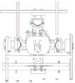
图1是本发明的用于纸箱无纺布提手安装机的正视图Fig. 1 is the front view of the present invention for the carton non-woven fabric handle installation machine
图2是现有技术中提手带安装到纸板的工艺流程Fig. 2 is the technological process of installing the handle belt to the cardboard in the prior art
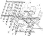
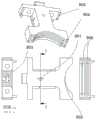
图3是本发明的用于纸箱无纺布提手安装机的立体视图Figure 3 is a perspective view of the present invention for the non-woven carton handle installation machine
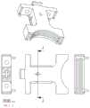
图4是本发明的用于纸箱无纺布提手安装机的部分零部件的细节视图Figure 4 is a detailed view of some components of the present invention for the non-woven carton handle installation machine
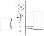
图5是本发明的用于纸箱无纺布提手安装机提手裁切供给机构的相关视图5 is a related view of the handle cutting and supplying mechanism for the carton non-woven fabric handle installation machine of the present invention
图6-图13是提手裁切供给机构的给料工艺流程图Fig. 6-Fig. 13 are the flow chart of the feeding process of the handle cutting and feeding mechanism
图14是提手翻转转移安装机构的驱动结构视图Figure 14 is a view of the drive structure of the handle flipping transfer installation mechanism
图15是提手翻转转移安装机构中的支撑结构和通气结构视图Figure 15 is a view of the support structure and ventilation structure in the handle flip transfer installation mechanism
图16是提手翻转转移安装机构中的通气结构细节视图Figure 16 is a detailed view of the ventilation structure in the handle flip transfer installation mechanism
图17是转盘转动轴的详细结构视图Fig. 17 is a detailed structural view of the rotary shaft of the turntable
图18是配气轴的详细结构视图Fig. 18 is a detailed structural view of the valve shaft
图19是真空泵以及气路的结构视图Fig. 19 is a structural view of a vacuum pump and a gas path
图20a是第一实施例中转盘转动轴上通气孔与提手安装弧形件的连通方式视图Figure 20a is a view of the communication mode between the ventilation hole on the rotating shaft of the turntable and the mounting arc of the handle in the first embodiment
图20b是第二实施例中配气轴与转盘转动轴的配合结构视图Figure 20b is a view of the fitting structure of the gas distribution shaft and the rotary shaft of the turntable in the second embodiment
图21是真空管与提手安装弧形件的连接结构视图一Figure 21 is a view of the connection structure between the vacuum tube and the handle
图22是真空管与提手安装弧形件的连接结构视图二Figure 22 is a second view of the connection structure between the vacuum tube and the handle installation arc
图23-图24是提手翻转转移安装机构的详细视图Figures 23-24 are detailed views of the handle flip transfer mounting mechanism
图25-图26是提手安装弧形件结构的详细视图Figures 25-26 are detailed views of the handle mounting arc structure
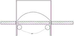
图27是提手承接抹平机构的详细视图Figure 27 is a detailed view of the handle receiving the troweling mechanism
图28-29是提手承接抹平机构的工作示意图Figure 28-29 is the working schematic diagram of the handle to undertake the leveling mechanism
图30是第一实施例的各个通气孔的通气循环图Fig. 30 is a ventilation cycle diagram of each ventilation hole in the first embodiment
图31是提手翻转转移安装机构的内部安装结构视图Figure 31 is a view of the internal installation structure of the handle flip transfer installation mechanism
图32a-32d是第一实施例中的提手带转移安装工艺流程图Figures 32a-32d are flowcharts of the process flow of the transfer and installation of the handle strap in the first embodiment
图33a-33f是第二实施例中的提手带转移安装工艺流程图Figures 33a-33f are flowcharts of the transfer and installation process of the handle strap in the second embodiment
图中,机架4,提手裁切供给机构1,提手翻转转移安装机构2,提手承接抹平机构3,提手带100,纸板101,粘结结构103,直线驱动机构203,第一收放卷辊201,第二收放卷辊202,柔性循环承载结构204,上压辊206,下压辊205,牵引夹钳211,上引导块209,下引导块207,第一支撑墙板208,第二支撑墙板210,第一固定支撑盘301,第二固定支撑盘302,配气轴306,从动齿轮305,分割器输出齿轮304,凸轮分割器303,转盘转动轴401,键部分501,空腔结构505,第一阶梯孔502,第二阶梯孔503,左侧的配气轴端部的通气孔通过配气轴真空管601,真空泵602,四个通气孔504,第二通气孔605,第三通气孔606,第四通气孔607,第一通气孔604,提手带转移安装组件705,贴带转盘603,第一真空管701,第二真空管702,第三真空管703,第四真空管704,提手带安装件轨道801,提手带安装件滑块802,提手安装弧形件803,升降叉806,导向柱805,压缩弹簧804,拉簧810,限位柱807,驱动气缸4002,升降驱动连接件4001,十字形块状结构4004,执行块结构4003,下通孔904,上通孔905,真空腔结构与通孔901,弧形面902,弧形承托板2006,矩形通孔2007,开孔涂胶纸板2001,输送导向杆2002,抹平件2003,抹平滑动件2004,承托基座2005,第一抹平轮3001,第二抹平轮3002。In the figure, the frame 4, the handle cutting and supplying mechanism 1, the handle turning and transferring installation mechanism 2, the handle receiving and leveling mechanism 3, the handle belt 100, the cardboard 101, the bonding structure 103, the linear driving mechanism 203, the first A rewinding and unwinding roller 201, a second rewinding and unwinding roller 202, a flexible circulating bearing structure 204, an upper pressing roller 206, a lower pressing roller 205, a traction clamp 211, an upper guide block 209, a lower guide block 207, a first support wall plate 208, second support wall plate 210, first fixed support plate 301, second fixed support plate 302, gas distribution shaft 306, driven gear 305, splitter output gear 304, cam splitter 303, turntable rotation shaft 401, The key part 501, the cavity structure 505, the first stepped hole 502, the second stepped hole 503, the ventilation hole at the end of the gas distribution shaft on the left side passes through the gas distribution shaft vacuum pipe 601, the vacuum pump 602, the four ventilation holes 504, the second Air vent 605, third vent hole 606, fourth vent hole 607, first vent hole 604, handle belt transfer mounting assembly 705, tape turntable 603, first vacuum tube 701, second vacuum tube 702, third vacuum tube 703, Fourth vacuum tube 704 , handle belt mounting rail 801 , handle belt mounting slider 802 , handle mounting arc 803 , lift fork 806 , guide post 805 , compression spring 804 , tension spring 810 , limit post 807 , drive cylinder 4002, lift drive connector 4001, cross-shaped block structure 4004, execution block structure 4003, lower through hole 904, upper through hole 905, vacuum chamber structure and through hole 901, arc surface 902, arc support Plate 2006, rectangular through hole 2007, perforated glued cardboard 2001, conveying guide rod 2002, trowel 2003, trowel slide 2004, support base 2005, first trowel 3001, second trowel 3002 .
具体实施方式:Detailed ways:
下面结合图及具体实施例详述本发明:The present invention is described in detail below in conjunction with the drawings and specific embodiments:
参见图1,用于纸箱无纺布提手安装机主要包括几个工作模块:机架4、提手裁切供给机构1、提手翻转转移安装机构2、提手承接抹平机构3、纸板输送机构(图中未详细示出)。其中机架4用于固定和支撑各个工作模块,其支撑形式不仅仅局限于图中的型材组成的框架式结构,同样也可以采用其他的固定形式,例如通过墙板、横梁之类的固定件支撑。对于各个工作模块,具体的,提手裁切供给机构1用于对成卷的无纺布提手带进行定量定长的供给并裁切(图中未详细示出),其中提手带可以是任何可以构成带状的材料制成,其通过牵引辊被放卷,然后提手带的前端被进一步牵引,当输送指定长度时,提手带在靠近牵引辊的下游侧被切断,此时牵引辊还夹持着提手带的前端,方便进一步的牵引放卷,此外提手带的整个放卷过程中可以加入简易的储料机构,用于提手带的不停机放卷,同样还可以加入针对带材输送的张力调节机构。Referring to Figure 1, the non-woven handle installation machine for carton mainly includes several working modules:
其中,提手翻转转移安装机构2用于将提手裁切供给机构1上的被切断的提手带转移到提手带的安装工位,从而进行进一步的提手带的安装,该安装具体是将提手带两端分别穿过纸板的模切开口的两个部分,然后将提手带安装在涂有胶水的纸板上,其具体的安装过程可以参考图2。Wherein, the handle overturning and transferring
参见图2,首先,提手裁切供给机构1将提手带100供给并切断,然后提手带被提手翻转转移安装机构2转移到靠近纸板101的上方位置,并且此时提手带的中间部分形成了弯曲部分,该弯曲部分是形成提手的关键结构,然后通过翻转转移安装机构2以及提手承接抹平机构3的配合将提手带100两端的水平部分分别穿过纸板101上的两个开口从而使得两端的水平部分转变形成大致的竖直状态,最后通过提手承接抹平机构3的作用将竖直的提手带部分抹平并且通过粘结结构103粘贴在纸板101上,其中粘结结构可以采用多种连接方式,例如胶水粘贴。Referring to FIG. 2, first, the handle cutting and supplying
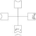
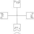
接下来通过更加详细的图来说明各个工作模块的具体结构,参见图3,其中,提手裁切供给机构1设置有三个,分别布置在提手带被提手翻转转移安装机构2左侧、上侧和右侧,其中左侧的提手裁切供给机构1与上侧的提手裁切供给机构1成90°布置,右侧的提手裁切供给机构1和上侧的提手裁切供给机构1成90°布置,从而形成了三个工位,设置三个上料工位有利于提高工作效率,对于工作效率提高的技术内容将在后文中介绍,三个提手裁切供给机构1如图4所示。Next, the specific structure of each working module will be described with more detailed diagrams. Referring to FIG. 3 , there are three handle cutting and supplying
对于提手裁切供给机构1的具体内部结构,参见图5,提手裁切供给机构1包括直线驱动机构203、裁切供给装置、以及提手带卷支撑装置(图中未示出),其中,裁切供给装置包括第一收放卷辊201、第二收放卷辊202、柔性循环承载结构204、上压辊206、下压辊205、牵引夹钳211,上引导块209、下引导块207、第一支撑墙板208、第二支撑墙板210、墙板基座。For the specific internal structure of the handle cutting and supplying
柔性循环承载结构204可以是柔性皮带结构或者链条结构或者其他能够进行收放卷的柔性材料。The flexible endless
其中墙板基座上设置有平行设置的第一支撑墙板208和第二支撑墙板210,其中第一支撑墙板208和第二支撑墙板210可以与墙板基座一体成型或者是固定设置。其中第一支撑墙板208和第二支撑墙板210的外侧面均设置有上引导块209、下引导块207,其中第一支撑墙板208的外侧面上从上到下依次设置有上引导块209、下引导块207,同样第二支撑墙板210的外侧面上从上到下依次设置有上引导块209、下引导块207,其中上引导块209呈弓箭形状设置,也就是中间是圆弧形边缘,两端是水平的引导边缘。其弧形的突出部分向上,并且上引导块209的底部的引导面分为三段,从提手带的输送方向来判断第一段引导面为水平段(该位置的描述是基于提手带水平输送的情形,提手带还存在其他角度输送的情形),第二段引导面为弧形面,该弧形面向上凹,并且弧形面的引导面所有部分都不低于第一水平段,第三段引导面与第一段引导面共面,该第三段引导面的开始部分与第二段引导面的弧形面的结束部分衔接,第一段引导面、第二段引导面、第三段引导面形成一个连续的引导面,下引导块207也分为三段引导面,该三段引导面分别与上引导块209的三段引导面一一对应、并且相互平行。The first
下引导块207的三段引导面设置在下引导块207的上端,因此,上引导块209与下引导块207形成一个弓箭形的用于对柔性循环承载结构进行引导的通道,柔性循环承载结构204能够在通道内循环运动,其中在下引导块207下侧设置有第一收放卷辊201、第二收放卷辊202,第一收放卷辊201、第二收放卷辊202分别被驱动机构驱动,能够实现正反转,能够对柔性循环承载结构204进行不同方向的收放,第一支撑墙板208、第二支撑墙板210的内侧设置有上压辊206、下压辊205,上压辊206、下压辊205能够转动,并且被驱动机构驱动,能够对提手带进行牵引输送,此外为了便于对提手带的引导基座上还设置有与下引导块207、上引导块209的引导面平行的提手带输送引导面,该引导面的竖直位置要低于下引导块207的引导面。The three-segment guide surfaces of the
其中,提手带被上、下压辊输送到一定距离之后,被预先张开的牵引夹钳211夹持,夹持后牵引夹钳211处于闭合状态,然后提手带被牵引夹钳211牵引到下游侧。The handle belt is transported to a certain distance by the upper and lower pressing rollers, and then clamped by the pre-opened traction clamps 211 . After clamping, the traction clamps 211 are in a closed state, and then the handle belt is pulled by the traction clamps 211 to the downstream side.
牵引夹钳211的具体结构为:牵引夹钳211包括基座部分和夹持部分,其中夹持部分被驱动装置驱动、可以实现开闭,牵引夹钳211的基座部分两端通过连接件分别与柔性循环承载结构连接,其中柔性循环承载结构在第一支撑墙板208外侧、第二支撑墙板210外侧都有设置。The specific structure of the
这样,在柔性循环承载结构往复运动的过程中,牵引夹钳211可以实现在引导轨道中的往复运动,为了让固定牵引夹钳211的基座部分的连接件能够通过第一支撑墙板208和第二支撑墙板210,在第一支撑墙板208和第二支撑墙板210上,在竖直方向上位于上引导块209、下引导块207之间设置有弓箭形的通槽结构,通槽结构用于引导连接件,从而引导限位牵引夹钳211在指定的轨道中往复运动。In this way, during the reciprocating movement of the flexible circulating load-bearing structure, the pulling
此外,柔性循环承载结构为带柔性材料,其一端的端头固定在第一收放卷辊201上,另一端的端头固定在第二收放卷辊202上,参见图5,第一收放卷辊201逆时针转动柔性循环承载结构204随着向左移动,第二收放卷辊202同样同步逆时针运动,此时牵引夹钳复位;第二收放卷辊202顺时针转动柔性循环承载结构204随着向右移动,第一收放卷辊201同样同步顺时针运动,此时牵引夹钳处于工作位置,等待提手带的输送。In addition, the flexible loop bearing structure is a flexible material, one end of which is fixed on the first take-up and unwinding
下面参考图6来具体说明提手带供给裁切:图6中示出的是布置在右侧的提手裁切供给机构1,其输送通道为竖直设置,布置在提手裁切供给机构1左侧的是提手翻转转移安装机构2(其中提手翻转转移安装机构2为示意性画法),第一步通过人工或者自动化机器人找到提手带卷的提手带的端部,然后将端部牵引到上压辊206和下压辊205之间被夹持,一开始,提手裁切供给机构1处于非转移工位,就是直线驱动机构203处于没有伸展的位置,同时也是提手裁切供给机构1远离提手翻转转移安装机构2的位置,上压辊206和下压辊205被驱动转动,从而牵引提手带前端,此时位于上压辊206和下压辊205下游侧的牵引夹钳211处于张开状态,随着提手带前端的进一步前进,提手带前端进入牵引夹钳211的夹爪内,此时停止上压辊和下压辊的输送,牵引夹钳211的夹爪闭合夹紧提手带(参见图7),然后牵引夹钳211按照弓箭形的路径向下游侧牵引提手带,并且上压辊和下压辊同步输送提手带,上下压辊的运动与牵引夹钳的运动是协同的,以便保证提手带的合理的张力(参见图8),此处值得说明的是,在理想状态下,由于上下压辊的输送速度与牵引夹钳的牵引速度相同,并且牵引夹钳的运动路径是弓箭形,提手带也应当形成弓箭形的结构,在实际运行中,提手带在被牵引的过程中并不是完全按照弧形进行分布的,但是由于牵引夹钳211的运动路径的路程等于提手带的前进距离,也就是提手带的供给长度,也就是说牵引夹钳的固定行程的往复运动能够保证提手带的定长输送,当其转移到提手翻转转移安装机构2上时,由于弧形引导板的相互挤压,同样能够将提手带挤压成弓箭形结构,理论上,弓箭形的提手带长度也就是每一次提手带的供给长度是等于基座上的弓箭形的实际长度的。这样能够更加稳定的保证提手带的定长供给。The following is a detailed description of the supply and cutting of the handle belt with reference to Figure 6: Figure 6 shows the handle cutting and supplying
下一步开始转移提手带,直线驱动机构203驱动杆开始伸缩,也就是向左运动,在其他工位就是向提手翻转转移安装机构2的方向运动,然后提手裁切供给机构1上的基座的弓箭形引导面上的提手带被挤压到提手翻转转移安装机构2上的弧形凹面结构,该弧形凹面结构与提手裁切供给机构1上的基座的弓箭形引导面是对应的,二者之间能够形成狭窄的通道用于挤压和容纳呈弓箭形结构的提手带。The next step starts to transfer the handle belt, and the drive rod of the
参见图9此时提手带被挤压保持,随后,需要通过切刀将提手带切断,切刀的位置应当是在输送方向上固定的,用于横向切割提手带,切刀设置在上压辊和下压辊的下游侧并且位于牵引夹钳的上游侧,其中切刀为更靠近下压辊和下压辊的位置(相对于牵引夹钳来说),切刀横向切割提手带,提手带此时变成提手,方便后续的进一步转移和安装(参见图10),此时直线驱动机构203的伸缩杆还是处于伸展状态并保持稳定,同时牵引夹钳的夹爪继续保持夹持的状态。Referring to Figure 9, the handle belt is squeezed and held, and then the handle belt needs to be cut off by a cutter. The position of the cutter should be fixed in the conveying direction for transversely cutting the handle belt. The downstream side of the upper and lower pressure rollers and on the upstream side of the pulling nip, where the cutter is closer to the lower and lower pressure rollers (relative to the pulling nip), and the cutter cuts the handle transversely At this time, the handle belt becomes a handle, which is convenient for subsequent further transfer and installation (see Figure 10). At this time, the telescopic rod of the
下一步,参见图11,在提手带被挤压夹紧的情况下,牵引夹钳的夹爪开始张开,以便释放提手带,由于提手带被提手裁切供给机构1和提手翻转转移安装机构2夹紧,提手带并不会掉落或者发生位移。Next, referring to Fig. 11, in the condition that the handle strap is squeezed and clamped, the jaws of the traction clamp begin to open, so as to release the handle strap, since the handle strap is cut by the handle to feed
下一步,参见图12,此时提手翻转转移安装机构2上设置有提手带保持装置,保持装置可以是吸风、夹持等其他能够保持提手带的结构,提手翻转转移安装机构2保持住提手带。直线驱动机构203的伸缩杆开始收缩,此时提手裁切供给机构1远离提手翻转转移安装机构2,提手带此时与提手裁切供给机构1分离。Next, referring to FIG. 12 , at this time, the handle overturning and transferring
下一步,参见图13,处于张开状态的牵引夹钳211进行返回运动,回到靠近切刀的初始位置,等待下一个提手带的进一步输送,此时完成单个循环。Next, referring to FIG. 13 , the pulling
需要说明的是,提手带在被切割之前,是通过上下压辊和牵引夹钳来保持的,所以整个输送过程中不会因为其朝向和布局发生掉落,并且因为提手带前端是被牵引后端是被张紧保持的因此,无论提手裁切供给机构1的安装位置如何,提手带都能够正常的进行输送,不会受到重力的影响。It should be noted that the handle belt is held by upper and lower pressing rollers and traction clamps before being cut, so it will not fall off due to its orientation and layout during the entire conveying process, and because the front end of the handle belt is The trailing end of the pulling is held under tension. Therefore, regardless of the installation position of the handle cutting and supplying
提手带被裁切之后,被牵引夹钳和提手翻转转移安装机构2保持此时提手带也不会脱落。After the handle strap is cut, it is held by the pulling clamp and the handle flipping
所以说,整个提手带的供给都是高效和稳定的。Therefore, the supply of the entire handle belt is efficient and stable.
对于提手翻转转移安装机构2的详细结构(参见图14),提手翻转转移安装机构2包括第一固定支撑盘301和第二固定支撑盘302,其他零部件被配气轴306支撑,配气轴306相对第一固定支撑盘301和第二固定支撑盘302固定,是不能够旋转的,第一固定支撑盘301和第二固定支撑盘302是被固定在机架上的,因此,配气轴306相对于机架也是固定的。For the detailed structure of the handle inversion and transfer installation mechanism 2 (see FIG. 14 ), the handle inversion and transfer
其他零部件套设在配气轴306上,其中从动齿轮305是与分割器输出齿轮304啮合连接的(图14中仅仅为示意图,从动齿轮305与分割器输出齿轮304啮合连接,也可以是其他的连接驱动方案),其中凸轮分割器303被电机驱动能够按照预定的运动规律进行旋转,从而带动分割器输出齿轮304的规律性旋转,然后带动从动齿轮305的规律性旋转,最终带动提手翻转转移安装机构2的规律性旋转。Other parts are sleeved on the
其中分割器输出齿轮304与其他零部件的连接关系将在后续的图中进一步进行阐述,参考图15,其中分割器输出齿轮304与从动齿轮305啮合,传动比设置为1:1,其中从动齿轮305套设在转盘转动轴401上,从动齿轮305可以带动转盘转动轴401相对于配气轴306转动,其中相关的连接关系参考图16,其中转盘转动轴401上端部分具有凸起的键部分,该键部分501(参见图17)与从动齿轮305的键槽相互配合,从而能够实现动力传动,从图15可得,转盘转动轴401两端设置有阶梯孔结构,详细结构参见图17,转盘转动轴401内部为空腔结构505圆筒形状,其左侧设置有第一阶梯孔502、右侧设置有第二阶梯孔503,在转盘转动轴401外表面与空腔结构505之间设置有通气孔,其中第一阶梯孔502、第二阶梯孔503中设置有轴承,其中轴承内圈套设在配气轴306的两端轴上(参见图15),对于配气轴306的详细结构,参见图18,配气轴内部开设置有空腔结构,并且通过左端的阶梯轴与外界连通,左侧的配气轴端部的通气孔通过配气轴真空管601与真空泵602连接(参见图19),真空泵602提供负压给配气轴306,配气轴306的中间的圆筒部分上设置有四个扇形开孔,四个扇形开孔与空腔结构是连通的,其中扇形开孔以配气轴306的中心轴线为中心线,分别错位分布在配气轴306的圆周方向上,其中每个扇形孔的角度为90°,并且连续的错开,以图18为例,其中从左边数,左到右的视图角度,剖面F-F中的第一扇形孔占据0°-90°的位置,剖面G-G中的第二扇形孔占据270°-360°的位置,剖面H-H中的第三扇形孔占据180°-270°的位置,剖面I-I中的第四扇形孔占据90°-180°的位置,并且各个剖面位于不同的横截面上,也就是位于配气轴306的中心轴线上的不同位置,并且第一扇形孔、第二扇形孔、第三扇形孔、第四扇形孔等距间隔设置,并且各个扇形孔分别与转盘转动轴401上的四个通气孔504一一对应,也就是在轴向上的位置一一对应。以便在转盘转动轴401的一个旋转周期中依次连续的给四个通气孔通气,其中参见图20a从右向左看,转盘转动轴401顺时针旋转,其通气顺序可以看截图的相关位置,首先最左侧的第一通气孔开始接通,然后旋转90°就是依次的第二通气孔605接通、旋转180°就是第三通气孔606接通、旋转270度就是第四通气孔607接通、旋转360度就回到开始位置第一通气孔604开始接通。The connection relationship between the
参见图21,此处为了保证下侧位置的提手带转移安装组件705和右侧位置的提手带转移安装组件705能够同时吸气,将各个通气孔在周向上设置一定的弧度,这样能够保证图20a中的第一通气孔和第二通气孔能够同时通气,能够起到提手带转移衔接的作用。Referring to FIG. 21 , in order to ensure that the handle belt transfer and
图20a中显示了第一、第二、第三、第四通气孔与提手带转移安装组件705之间的连接关系,其中a,b,c,d分别对应了四个不同的工作相位。在此状态下,第一通气孔连接在右侧的提手带转移安装组件705,第二通气孔连接在上侧的提手带转移安装组件705,第三通气孔连接在左侧的提手带转移安装组件705,第四通气孔连接在下侧的提手带转移安装组件705。Figure 20a shows the connection relationship between the first, second, third, and fourth ventilation holes and the handle strap
值得注意的是,采用四个不同相位的情况下,每次只能实现一次给带,本案例中只能实现对右侧的提手带转移安装组件705进行给带。It is worth noting that in the case of using four different phases, only one feeding can be achieved at a time, and in this case, only the right handle strap
图20b中显示了所有通气孔在整个圆周内都是连通的,也就是说所有提手带转移安装组件705真空系统都是连通的,在该实施例中,是可以同时进行三工位上料的,此时为了单独控制提手带转移安装组件705的吸风通断,设置四个被控制器控制的通气阀结构,通过通气阀的闭合可以实现每个提手带转移安装组件705的精准吸风控制,从而更高效的转移提手带,其中单工位给料模式和三工位给料模式需要更换不同的配气轴。Figure 20b shows that all the vent holes are connected in the entire circumference, that is to say, all the vacuum systems of the handle belt
其中,提手带转移安装组件705的用途和安装位置将在下文中进一步阐述。Among them, the purpose and installation position of the handle strap
其中,提手翻转转移安装机构2还包括有贴带转盘603,贴带转盘套设在转盘转动轴401上,贴带转盘603与转盘转动轴401固定连接,二者可以保持共同转动状态,二者都相对于配气轴306转动。也就是说凸轮分割器303可以带动贴带转盘603顺时针转动,从右向左的视角。Wherein, the handle overturning and transferring
进一步的,图21显示了贴带转盘603右侧的局部视图,其中贴带转盘603上安装有提手带转移安装组件705,提带转移安装组件705有四个每个质之间成90°均匀分布,并且四个提带转移安装组件705分别与提手裁切供给机构1一一对应,提手裁切供给机构1将被裁切的提手带转移到提手带转移安装组件705上。Further, FIG. 21 shows a partial view of the right side of the
提手带转移安装组件705上设置有真空腔结构(在后文详细介绍,主要功能用于吸附提手带带),其中每个真空腔结构分别通过第一真空管701、第二真空管702、第三真空管703、第四真空管704与转盘转动轴401上的通气孔连接,其中第一真空管701与第一通气孔604连接,第二真空管702与第二通气孔605连接,第三真空管703与第三通气孔606连接,第四真空管704与第四通气孔607连接,具体的连接图参见图22,此处需要说明的是,图中的真空管仅仅是示意图,真空管是柔性的管实际安装过程中是可以进行合理布局的,不会占用太大的空间,也不会与其他零部件产生干涉,由于贴带转盘603和转盘转动轴401都是同步转动的,因此连接在二者之间的真空管同样是转动的,三者实质上是相对静止的,并不会产生干涉。The handle belt transfer and
参见图23,进一步的详细介绍提手带转移安装组件705,其中安装组件中的提手带安装件轨道801固定安装在贴带转盘603上,提手带安装件轨道801上滑动安装有提手带安装件滑块802,提手带安装件滑块802上则固定安装有提手安装弧形件803,提手安装弧形件803上开设有通气孔,该通气孔与真空管连通。Referring to FIG. 23, the handle belt
其中提手安装弧形件803上还套设有升降叉806,升降叉806可以相对提手安装弧形件803运动,升降叉806上还设有导向柱805,导向柱穿过提手安装弧形件803上的通孔,其中导向柱805穿过该通孔之后的部分设置有锁紧螺母,导向柱805没有穿过该通孔的部分套设有压缩弹簧804。The lifting
下面通过图24进一步阐述其具体的连接结构,提手安装弧形件803背面安装有第一弹簧固定柱(参见图24中的虚线部分),其中拉簧810一端固定在第一弹簧固定柱上,另一端固定在第二弹簧固定柱上,拉簧810从而能够对提手安装弧形件803提供一个向上的拉力,并且拉簧810以及第一弹簧固定柱和第二弹簧固定柱设置有两组,并且两组对称设置,并且贴带转盘603上设置有限位柱807、808,其中限位柱能够对提手安装弧形件803进行限位,防止其继续向上运动,在拉簧810的弹簧力作用下,提手安装弧形件803保持静止。The specific connection structure will be further explained below with reference to FIG. 24 . The back of the handle mounting
此外,由于升降叉806上设有导向柱805,导向柱805上套设有压簧,导向柱一端设置有螺母,因此,升降叉处于一个绷紧的状态被压缩弹簧804支撑保持静止状态,其目的在于保证升降叉的稳定性,防止其产生剧烈的震动,其中,压缩弹簧804的弹性系数比拉伸弹簧的弹性系数的绝对值大。从而能够保证升降叉上端被施加作用力时,拉伸弹簧先发生变形,然后当提手安装弧形件803不能继续向下移动时,压缩弹簧才明显的被压缩,最后升降叉开始明显的下降。In addition, since the
对于升降叉的的升降驱动,参见图31,第二固定支撑盘302安装固定安装有两个驱动气缸4002,两个驱动气缸4002伸缩杆竖直向下设置,并且伸缩杆端部连接有升降驱动连接件4001,升降驱动连接件4001一部分为十字形块状结构4004,该部分设置于第二固定支撑盘302外侧,十字形块状结构4004上端还伸出有执行块结构4003,该执行块结构4003的延伸方向垂直于十字形块状结构的平面,该延伸方向平行于配气轴306的中心轴线。并且在第二固定支撑盘302中间位置设置有竖直的导向通槽,供执行块结构穿过以便深入第二固定支撑盘302的内侧,采用这样的结构能够使得升降驱动连接件4001竖直升降,在非工作行程,升降驱动连接件4001的执行块结构位于靠近配气轴306的近圆心位置,这样随着贴带转盘603的旋转,提手安装弧形件803上套设的升降叉806不会与升降驱动连接件4001产生干涉和碰撞,在工作行程,升降驱动连接件4001的执行块结构下压升降叉,并带动提手安装弧形件803的升降运动以及升降叉的升降运动。For the lift drive of the lift fork, see FIG. 31 , the second fixed
对于提手安装弧形件803的具体结构,参见图24,其中提手安装弧形件803的下端为弓箭形的弧形凹陷面,用于与提手裁切供给机构1上的弓箭形弧形面匹配贴合,其中在弓箭形面的水平段,各设置有两个下通孔904(参见图26),以便升降叉806穿过,其中提手安装弧形件803呈大字形结构,提手安装弧形件803上端的水平矩形块结构两端设置有上通孔905,升降叉806先穿过上通孔905然后穿过下通孔904,升降叉806可以相对上通孔905和下通孔904上下运动,提手安装弧形件803内部具有真空腔结构,真空腔结构与通孔901连通,并且在弧形面上开设有多条例如三条细长的开口以便于真空腔结构连通,这样通过三条细长的开口就能实现提手带的真空吸附,提手带被提手裁切供给机构1挤压到提手安装弧形件803上的弧形面902上之后,被三条细长的开口吸附从而实现提手带的转移。For the specific structure of the
参考图21,提手裁切供给机构1设置在提手翻转转移安装机构2的左侧、上侧、右侧,并且实现同时给料,在下端的提手带被安装之后,下端的提手安装弧形件803是不存在提手带的,因此需要从右侧的提手带安装件上面补给,此时需要顺时针转动提手安装弧形件803,将位于右侧的提手安装弧形件803转动到下侧开始新的提手安装,在继续连续完成三次提手安装之后,所有的提手带安装完成,此时需要暂停提手安装弧形件803的旋转,进行单工位提手带转移动作。然后继续下一个循环。Referring to FIG. 21 , the handle cutting and
参考图27,下面将详细介绍提手承接抹平机构3,提手承接抹平机构3包括弧形承托板2006,弧形承托板为上凸形的弓箭形状,该形状与提手安装弧形件803的弧形面配合,并且一一对应,弧形承托板2006上设置有矩形通孔2007,并且该矩形通孔2007与提手安装弧形件803的一侧面连通,该侧面位于开孔涂胶纸板2001输送方向的下游侧,其中连通的侧面为下游侧,非连通的侧面为上游侧,开孔涂胶纸板2001的输送方向为从非连通侧面指向连通侧面,并且矩形通孔2007与开孔涂胶纸板2001上的开孔位置相对应,并且允许升降叉通过,在开孔涂胶纸板2001下方设置有用于承托开孔涂胶纸板2001的输送导向杆2002,输送导向杆2002位于弧形承托板2006两端的外侧,进一步的在开孔涂胶纸板2001下方还设置有抹平件2003,抹平件2003可升降的设置在抹平滑动件2004上,抹平滑动件2004则安装在承托基座2005上,可以左右滑动,并且被驱动,承托基座2005和弧形承托板2006中间形成有通道,允许开孔涂胶纸板2001通过,准确来讲,开孔涂胶纸板2001位于输送导向杆2002和弧形承托板2006之间。Referring to FIG. 27 , the handle receiving and
其中,抹平件2003上转动安装有第一抹平轮3001、第二抹平轮3002,其中左侧的抹平件2003可以上下左右移动,右侧的抹平件同样可以上下左右移动,其中右侧的第一抹平轮3001为单向轮,只能顺时针转动,左侧第一抹平轮3001只能逆时针转动,这样设置是因为,参见图29,当升降叉下压提手带,提手带穿过开孔涂胶纸板2001的开孔之后,提手带的两端被夹紧在第一抹平轮3001与升降叉的左侧叉的叉壁右侧之间,由于左侧的第一抹平轮3001可以逆时针旋转,所以提手带随着升降叉的向下运动被夹持输送并拉直,同样,右侧的第一抹平轮3001能够顺时针转动,同样有侧提手带部分被进一步拉直,与此同时当升降叉上升时,由于左侧第一抹平轮3001不能顺时针转动,右侧的第一抹平轮3001不能逆时针转动,因此,通过第一抹平轮3001与提手带的部分的摩擦力,使得提手带被持续保持并拉直,其中第一抹平轮3001应当设置较大摩擦力结构,例如轮表面设置纹路或者套设橡胶结构。其中升降叉的叉壁应当设置耐磨较小摩擦力结构,例如设置光滑的表面。在此情况下,升降叉在下降时由于第一抹平轮3001的滚动可以顺利带动提手带向下拉直,在升降叉上升时,由于第一抹平轮3001的静止不能转动,可以保持住提手带不上升,并且叉壁设置光滑面,升降叉更容易与提手带分离。The
进一步的,介绍抹平机构的抹平功能,参见图28,在升降叉传送提手带时,第一抹平轮3001和第二抹平轮3002距离开孔涂胶纸板2001下表面有一小段的距离,在升降叉上升之后,第一抹平轮3001和第二抹平轮3002被驱动上升并贴进开孔涂胶纸板2001下表面,并且与弧形承托板2006的下表面相互配合准备对提手带两端的挤压,第一抹平轮3001和第二抹平轮3002构成的抹平机构为左右两个,并且向两端运动开始挤压提手带的两端,从而将提手带的两端通过连接件粘贴在开孔涂胶纸板2001的下表面,然后左右两个抹平机构恢复到原始位置,最终完成提手带的安装,提手带安装完成之后,开孔涂胶纸板2001被输送到下游侧,进入下一步处理。Further, the troweling function of the troweling mechanism is introduced. Referring to FIG. 28 , when the lifting fork transmits the handle belt, the
下面进一步的介绍一个周期整个提手带的安装过程:The following further introduces the installation process of the entire handle strap in one cycle:
首先参考图30:其中横坐标为转盘转动轴401的转动角度,纵坐标为相应的通气孔的通气情况。其中高位表示接通提供负压,低位表示没有接通表示没有负压。需要注意的是该循环图不是工作时序图,在转盘转动轴401实际的转动过程中有停顿,并且通过转盘转动轴401的负压还能通过真空发生器进行控制。Referring first to FIG. 30 : the abscissa is the rotation angle of the
第一步骤:供料步骤The first step: feeding step
开始提手带转移时,按照图20a的真空管连接方式连接,并且按照左侧、上侧、右侧、下侧的位置设置提手翻转转移安装机构2中的提手带转移安装组件705。When starting the transfer of the handle belt, connect according to the vacuum tube connection method in Figure 20a, and set the handle belt transfer and
并且此时的提手翻转转移安装机构2处于静止状态,提手带转移安装组件705同样处于静止状态。And at this time, the handle overturning and transferring
1、当采用单工位给料方案时,从图20a以及图30可知,第一通气孔已经开始进入吸气状态,由于第一通气孔具有周向的宽度,因此当其正好位于0°之前就已经开始吸气。1. When the single-station feeding scheme is adopted, it can be seen from Figure 20a and Figure 30 that the first ventilation hole has begun to enter the suction state. Since the first ventilation hole has a circumferential width, when it is just before 0° Just started breathing.
此时,与第一通气孔连接的右侧工位提手带转移安装组件705已经吸气(由于通气口只有一半因此负压相对较小,但是能保证提手带被吸附),与第四通气孔连接的下侧工位提手带转移安装组件705即将结束吸气(由于通气口只有一边因此负压相对较小,但是能保证提手带被吸附)。At this time, the right side handle belt transfer and
此时执行提手带供料工作,参见图5,牵引夹钳处于工作位置,等待提手带的输送。At this time, the feeding work of the handle belt is performed, see Figure 5, the traction clamp is in the working position, waiting for the conveying of the handle belt.
图6中示出的是布置在右侧的提手裁切供给机构1,通过人工或者自动化机器人找到提手带卷的提手带的端部,然后将端部牵引到上压辊206和下压辊205之间被夹持,一开始,提手裁切供给机构1处于非转移工位,就是直线驱动机构203处于没有伸展的位置,同时也是提手裁切供给机构1远离提手翻转转移安装机构2的位置,上压辊206和下压辊205被驱动转动,从而牵引提手带前端,此时位于上压辊206和下压辊205下游侧的牵引夹钳211处于张开状态,随着提手带前端的进一步前进,提手带前端进入牵引夹钳211的夹爪内,此时停止上压辊和下压辊的输送,牵引夹钳211的夹爪闭合夹紧提手带(参见图7),然后牵引夹钳211按照弓箭形的路径向下游侧牵引提手带,并且上压辊和下压辊同步输送提手带,上下压辊的运动与牵引夹钳的运动是协同的,以便保证提手带的合理的张力(参见图8),此处值得说明的是,在理想状态下,由于上下压辊的输送速度与牵引夹钳的牵引速度相同,并且牵引夹钳的运动路径是弓箭形,提手带也应当形成弓箭形的结构,在实际运行中,提手带在被牵引的过程中并不是完全按照弧形进行分布的,但是由于牵引夹钳211的运动路径的路程等于提手带的前进距离,也就是提手带的供给长度,也就是说牵引夹钳的固定行程的往复运动能够保证提手带的定长输送,当其转移到提手翻转转移安装机构2上时,由于弧形引导板的相互挤压,同样能够将提手带挤压成弓箭形结构,理论上,弓箭形的提手带长度也就是每一次提手带的供给长度是等于基座上的弓箭形的实际长度的。这样能够更加稳定的保证提手带的定长供给。Shown in FIG. 6 is the handle cutting and
下一步开始转移提手带,直线驱动机构203驱动杆开始伸缩,也就是向左运动,在其他工位就是向提手翻转转移安装机构2的方向运动,然后提手裁切供给机构1上的基座的弓箭形引导面上的提手带被挤压到提手安装弧形件803上的弧形凹面结构,该弧形凹面结构与提手裁切供给机构1上的基座的弓箭形引导面是对应的,二者之间能够形成狭窄的通道用于挤压和容纳呈弓箭形结构的提手带。The next step starts to transfer the handle belt, and the drive rod of the
参见图9此时提手带被挤压保持,随后,需要通过切刀将提手带切断,切刀的位置应当是在输送方向上固定的,用于横向切割提手带,切刀设置在上压辊和下压辊的下游侧并且位于牵引夹钳的上游侧,其中切刀为更靠近下压辊和下压辊的位置(相对于牵引夹钳来说),切刀横向切割提手带,提手带此时变成提手,方便后续的进一步转移和安装(参见图10),此时直线驱动机构203的伸缩杆还是处于伸展状态并保持稳定,同时牵引夹钳的夹爪继续保持夹持的状态。Referring to Figure 9, the handle belt is squeezed and held, and then the handle belt needs to be cut off by a cutter. The position of the cutter should be fixed in the conveying direction for transversely cutting the handle belt. The downstream side of the upper and lower pressure rollers and on the upstream side of the pulling nip, where the cutter is closer to the lower and lower pressure rollers (relative to the pulling nip), and the cutter cuts the handle transversely At this time, the handle belt becomes a handle, which is convenient for subsequent further transfer and installation (see Figure 10). At this time, the telescopic rod of the
下一步,参见图11,在提手带被挤压夹紧的情况下,牵引夹钳的夹爪开始张开,以便释放提手带,由于提手带被提手裁切供给机构1和提手翻转转移安装机构2夹紧,提手带并不会掉落或者发生位移。Next, referring to Fig. 11, in the condition that the handle strap is squeezed and clamped, the jaws of the traction clamp begin to open, so as to release the handle strap, since the handle strap is cut by the handle to feed
下一步,参见图12,直线驱动机构203的伸缩杆开始收缩,此时提手裁切供给机构1远离提手翻转转移安装机构2,提手带此时与提手裁切供给机构1分离,由于提手翻转转移安装机构2上的提手安装弧形件803处于吸风状态,所以提手带被吸附固定。Next, referring to FIG. 12 , the telescopic rod of the
下一步,参见图13,处于张开状态的牵引夹钳211进行返回运动,回到靠近切刀的初始位置,等待下一个提手带的进一步输送,此时完成单个循环。Next, referring to FIG. 13 , the pulling
下一步,参见图32a,右侧工位的提手安装弧形件803吸取提手带,然后整个贴带转盘603顺时针旋转90°整个过程中原来位于右侧的提手安装弧形件803持续吸附提手带并且运动到下侧位置,原来的上侧位置提手安装弧形件803运动到右侧位置,随后,此时位于下侧位置的提手安装弧形件803向下运动,并且保持吸风状态,然后运动到将提手安装弧形件803的弧形部分与弧形承托板2006形成挤压通道,将提手带挤压在二者中间,此时参见图32b的情况。Next, referring to Fig. 32a, the
下一步,参见图32c,该提手带安装分解为多个步骤,步骤a,暂时停止所有通气孔通气,由于此时提手带被挤压夹持,因此不需要提供负压,此时右侧工位的提手安装弧形件803还没有开始转移提手带,暂时不需要通气;升降叉向下运动,将提手带两端带入并穿过弧形承托板2006的矩形通孔,并且提手带一侧与第一抹平轮3001接触,另一端与升降叉的侧面接触,此时第一抹平轮3001是可以单向运动的,这样使得提手带更容易向下滑动;步骤b,当提手带完全进入时,升降叉开始上升恢复原位,此时第一抹平轮3001不能转动,因此将提手带保持固定位置,防止提手带被升降叉带回;步骤c,此时两端的第一抹平轮3001分别向上运动,压紧提手带,然后向各自两侧运动,也就是左侧的第一抹平轮3001向左运动,右侧的第一抹平轮向右侧运动,从而达到提手带的抹平,以及将提收带粘贴在纸板上的效果。步骤d,然后左侧的第一抹平轮3001向右侧运动之后向下侧运动恢复到原来的位置,右侧的第一抹平轮3001向左侧运动之后向下侧运动并恢复到原来的位置,此时提手带已经成功的安装到纸板上,步骤e,提手安装弧形件803上升运动恢复到原来的下侧位置,此时提手安装弧形件803让出了较大的空隙,安装有提手带的纸板按照垂直于图32c的纸面向外输送。Next, referring to Figure 32c, the installation of the handle strap is broken down into multiple steps. In step a, the ventilation of all ventilation holes is temporarily stopped. Since the handle strap is squeezed and clamped at this time, it is not necessary to provide negative pressure. The
下一步参见图32d,此时打开通气开关右侧位置和下侧位置的提手安装弧形件803通气,然后从此时的右侧提手安装弧形件803开始下一个提手带转移安装的循环。Next, referring to FIG. 32d, at this time, open the
2、当采用三工位给料时,此时通气孔全程是打通的,该给料方案与单工位给料方案的区别主要在于左侧、上侧、右侧三个工位同时供料,此时则需要设置四个单独控制提手安装弧形件803的通气开关,以便更灵活的进行控制。2. When three-station feeding is used, the ventilation holes are opened throughout the whole process. The difference between this feeding scheme and the single-station feeding scheme is that the three stations on the left, upper and right are simultaneously feeding materials. , at this time, it is necessary to set up four ventilation switches for individually controlling the handle installation arc-shaped
采用三工位给料安装的效率要大于单工位的给料安装效率。The efficiency of three-station feeding installation is greater than that of single-station feeding installation.
其中三个提手裁切供给机构1,左侧、上侧、右侧的提手裁切供给机构1同时给料,并且将提手带同时转移到提手安装弧形件803上,此时设置有四个单独控制左侧、上侧、右侧、下侧的提手安装弧形件803吸气通断的通断阀结构,在实现提手带从提手裁切供给机构1转移到提手安装弧形件803上时,左侧、上侧、右侧的提手安装弧形件803具备负压功能吸附提手带并进行提手带供料,参见图33a-33b,然后将整个贴带转盘603旋转90度参见图33c,此时上侧、右侧、下侧的提手安装弧形件803具备提手带,贴带转盘603暂停旋转,等待下侧的提手安装弧形件803完成提手带的转移,在转移过程中,等待升降叉穿入提手带并且第一抹平轮将提手带挤压安装到纸板上之后,单独停止下侧提手安装弧形件803的负压参见图33c的从左到右的流程图,从而让下侧的提手安装弧形件803上升回归到原来的位置,然后再顺时针旋转90度,此时右侧、下侧的提手安装弧形件803具备提手带,再次执行上述提手带的安装,参见图33d,然后再顺时针旋转90,此时只剩下下侧的提手安装弧形件803具备提手带,第三次执行提手带的安装,参见图33e,等待安装完成之后,下侧的提手安装弧形件803上升回归到原位置,此时开始执行三工位提手带供料,开始执行下一个循环,参见图33f。Among them, three handle cutting and supplying
三工位给料与单工位给料仅仅在于吸气控制手段以及提手带给料手段的不同,除此之外的其他结构都是共用的,不存在区别。The difference between the three-station feeding and the single-station feeding is only in the suction control method and the feeding method of the handle, and other structures are shared, and there is no difference.
Claims (6)
Translated fromChinesePriority Applications (1)
| Application Number | Priority Date | Filing Date | Title |
|---|---|---|---|
| CN202010986297.9ACN112060682B (en) | 2020-09-18 | 2020-09-18 | Lifting handle belt transferring, installing and leveling device of lifting handle installing machine and using method thereof |
Applications Claiming Priority (1)
| Application Number | Priority Date | Filing Date | Title |
|---|---|---|---|
| CN202010986297.9ACN112060682B (en) | 2020-09-18 | 2020-09-18 | Lifting handle belt transferring, installing and leveling device of lifting handle installing machine and using method thereof |
Publications (2)
| Publication Number | Publication Date |
|---|---|
| CN112060682Atrue CN112060682A (en) | 2020-12-11 |
| CN112060682B CN112060682B (en) | 2022-01-25 |
Family
ID=73681738
Family Applications (1)
| Application Number | Title | Priority Date | Filing Date |
|---|---|---|---|
| CN202010986297.9AActiveCN112060682B (en) | 2020-09-18 | 2020-09-18 | Lifting handle belt transferring, installing and leveling device of lifting handle installing machine and using method thereof |
Country Status (1)
| Country | Link |
|---|---|
| CN (1) | CN112060682B (en) |
Cited By (1)
| Publication number | Priority date | Publication date | Assignee | Title |
|---|---|---|---|---|
| CN118991137A (en)* | 2024-10-26 | 2024-11-22 | 河南新印智能装备有限公司 | Handle erection equipment of roof form gift box |
Citations (5)
| Publication number | Priority date | Publication date | Assignee | Title |
|---|---|---|---|---|
| CN102602049A (en)* | 2012-03-21 | 2012-07-25 | 江苏方邦机械有限公司 | Paper bag handgrip pasting device |
| CN205631523U (en)* | 2016-04-06 | 2016-10-12 | 东莞市福莱利机械科技有限公司 | A carton handle automatic installation equipment |
| CN109016644A (en)* | 2018-08-27 | 2018-12-18 | 唐山新联印刷机械集团有限公司 | A kind of method and apparatus that packing case installs plastic handles |
| CN109109380A (en)* | 2018-08-06 | 2019-01-01 | 深圳市明合发纸品有限公司 | A kind of hot melt adhesive of carton eye ring wears deduction and its installation method automatically |
| KR102062374B1 (en)* | 2019-07-15 | 2020-01-03 | 주식회사 디에스이엔지 | Box handle inserting device |
- 2020
- 2020-09-18CNCN202010986297.9Apatent/CN112060682B/enactiveActive
Patent Citations (5)
| Publication number | Priority date | Publication date | Assignee | Title |
|---|---|---|---|---|
| CN102602049A (en)* | 2012-03-21 | 2012-07-25 | 江苏方邦机械有限公司 | Paper bag handgrip pasting device |
| CN205631523U (en)* | 2016-04-06 | 2016-10-12 | 东莞市福莱利机械科技有限公司 | A carton handle automatic installation equipment |
| CN109109380A (en)* | 2018-08-06 | 2019-01-01 | 深圳市明合发纸品有限公司 | A kind of hot melt adhesive of carton eye ring wears deduction and its installation method automatically |
| CN109016644A (en)* | 2018-08-27 | 2018-12-18 | 唐山新联印刷机械集团有限公司 | A kind of method and apparatus that packing case installs plastic handles |
| KR102062374B1 (en)* | 2019-07-15 | 2020-01-03 | 주식회사 디에스이엔지 | Box handle inserting device |
Cited By (1)
| Publication number | Priority date | Publication date | Assignee | Title |
|---|---|---|---|---|
| CN118991137A (en)* | 2024-10-26 | 2024-11-22 | 河南新印智能装备有限公司 | Handle erection equipment of roof form gift box |
Also Published As
| Publication number | Publication date |
|---|---|
| CN112060682B (en) | 2022-01-25 |
Similar Documents
| Publication | Publication Date | Title |
|---|---|---|
| CN113290838B (en) | Production and processing device for fireproof building curtain wall material aluminum-plastic plate | |
| CN109746674B (en) | LED flat lamp assembly line | |
| CN107585612B (en) | A kind of compounding machine automatic roll-changing device | |
| CN210083641U (en) | Film sticking machine for FPC flexible board | |
| CN106824845A (en) | Automatic gluing machine for plates | |
| CN112193876B (en) | Three-station handle belt transfer installation device of handle installation machine and use method thereof | |
| CN112060682A (en) | Lifting handle belt transferring, installing and leveling device of lifting handle installing machine and using method thereof | |
| CN116750251A (en) | Coil stock packaging film winding equipment and packaging film winding method | |
| CN116495536A (en) | Automatic winding device without winding core for waterproof membrane and winding method for waterproof membrane | |
| CN112265846B (en) | Single-station handle belt feeding device of handle belt mounting machine and feeding method thereof | |
| CN112208148B (en) | Three-station handle belt feeding device of handle belt installation machine and its use method | |
| CN107500015B (en) | Sponge sheet and double-sided tape laminating equipment | |
| CN204726752U (en) | The automatic end seal apparatus of large-scale coiled strip circumference overlay film | |
| CN218849550U (en) | Battery Packing Device | |
| CN213864606U (en) | Winding device of bag making machine with single-side opening and winding bag | |
| CN206446175U (en) | A semi-automatic box-gluing device feeding and conveying device | |
| CN111232696B (en) | Snatch charging equipment | |
| CN213264934U (en) | Device for controlling tension during production of flexible material | |
| CN209520585U (en) | LED flat plate lamp group founds line | |
| CN222223727U (en) | A printing device for producing packaging bags | |
| CN222138288U (en) | A new gluing mechanism for paper box processing | |
| CN220950365U (en) | Unreeling device for PVC/PE/PVDC composite hard sheet production | |
| CN113601898B (en) | A fully automatic fastening packaging production system | |
| CN113023412A (en) | Film conveying device | |
| CN217222217U (en) | Coating device with automatic feeding function |
Legal Events
| Date | Code | Title | Description |
|---|---|---|---|
| PB01 | Publication | ||
| PB01 | Publication | ||
| SE01 | Entry into force of request for substantive examination | ||
| SE01 | Entry into force of request for substantive examination | ||
| GR01 | Patent grant | ||
| GR01 | Patent grant | ||
| TR01 | Transfer of patent right | Effective date of registration:20230908 Address after:Room 417, West Technology Research and Innovation Building, Wenzhou Vocational and Technical College, Chashan Street, Ouhai District, Wenzhou City, Zhejiang Province, 325000 Patentee after:Mingchuang Qibo Wenzhi Technology Transfer and Transformation (Wenzhou) Co.,Ltd. Address before:325000 Wenzhou City National University Science Park incubator, No. 38 Dongfang South Road, Ouhai Economic Development Zone, Wenzhou, Zhejiang Patentee before:WENZHOU VOCATIONAL & TECHNICAL College | |
| TR01 | Transfer of patent right |