CN112059687A - Automatic feeding device - Google Patents
Automatic feeding deviceDownload PDFInfo
- Publication number
- CN112059687A CN112059687ACN202010823380.4ACN202010823380ACN112059687ACN 112059687 ACN112059687 ACN 112059687ACN 202010823380 ACN202010823380 ACN 202010823380ACN 112059687 ACN112059687 ACN 112059687A
- Authority
- CN
- China
- Prior art keywords
- materials
- moving
- automatic feeding
- sliding
- feeding device
- Prior art date
- Legal status (The legal status is an assumption and is not a legal conclusion. Google has not performed a legal analysis and makes no representation as to the accuracy of the status listed.)
- Pending
Links
Images


Classifications
- B—PERFORMING OPERATIONS; TRANSPORTING
- B23—MACHINE TOOLS; METAL-WORKING NOT OTHERWISE PROVIDED FOR
- B23Q—DETAILS, COMPONENTS, OR ACCESSORIES FOR MACHINE TOOLS, e.g. ARRANGEMENTS FOR COPYING OR CONTROLLING; MACHINE TOOLS IN GENERAL CHARACTERISED BY THE CONSTRUCTION OF PARTICULAR DETAILS OR COMPONENTS; COMBINATIONS OR ASSOCIATIONS OF METAL-WORKING MACHINES, NOT DIRECTED TO A PARTICULAR RESULT
- B23Q7/00—Arrangements for handling work specially combined with or arranged in, or specially adapted for use in connection with, machine tools, e.g. for conveying, loading, positioning, discharging, sorting
- B23Q7/04—Arrangements for handling work specially combined with or arranged in, or specially adapted for use in connection with, machine tools, e.g. for conveying, loading, positioning, discharging, sorting by means of grippers
Landscapes
- Engineering & Computer Science (AREA)
- Mechanical Engineering (AREA)
- Feeding Of Articles To Conveyors (AREA)
Abstract
Description
Translated fromChinese技术领域technical field
本发明属于智能制造领域,具体涉及一种可自动上料的自动上料装置。The invention belongs to the field of intelligent manufacturing, and in particular relates to an automatic feeding device capable of automatic feeding.
背景技术Background technique
目前,机器人3D智能机床供料系统项目的大部分上料工作是人工上料,人工上料时人工把物料传输并挪移到需要的工位,人工上料速度慢,已经不能满足提高生产效率的需要,也不能满足批量生产制作的需要。At present, most of the feeding work of the robot 3D intelligent machine tool feeding system project is manual feeding. During manual feeding, the material is manually transported and moved to the required station. The manual feeding speed is slow, which can no longer meet the needs of improving production efficiency. needs, and cannot meet the needs of mass production.
发明内容SUMMARY OF THE INVENTION
为了解决上述问题,本发明提供了一种可自动上料的自动上料装置。In order to solve the above problems, the present invention provides an automatic feeding device that can automatically feed materials.
本发明的技术方案为:The technical scheme of the present invention is:
一种自动上料装置,包括逐级阶梯地上料以输送物料到预定高度的阶梯上料机、对阶梯上料机输送到位后的物料进行3D识别以确认物料方位的3D识别装置、对识别后的物料进行自动抓取挪移的机械手。An automatic feeding device, comprising a step feeding machine for feeding materials step by step to convey materials to a predetermined height, a 3D recognition device for performing 3D recognition on the materials after the step feeding machine has been transported in place to confirm the orientation of the materials, and a 3D recognition device for A manipulator that automatically grabs and moves the materials.
本发明中,阶梯上料机输送物料,本发明输送的物料尤其适用于棒状的物料,当然也可以输送其他形状的物料,阶梯上料机输送物料到上方位置后,3D识别装置通过视觉识别识别出物料的方位和物料形态信息,并将信息传输给机械手,机械手按照物料信息进行抓取挪移。In the present invention, the stair loader conveys the material. The material conveyed by the invention is especially suitable for rod-shaped materials. Of course, it can also convey materials of other shapes. After the stair loader conveys the material to the upper position, the 3D recognition device recognizes it through visual recognition. The orientation and shape information of the material is output, and the information is transmitted to the manipulator, and the manipulator grasps and moves according to the material information.
本发明所述的阶梯上料机包括:多列位置依次增高地同时上下移动地输送物料的移动部、依次穿插在移动部内用于接紧邻的移动部所输送的物料的固定不动的固定部、将机械手抓取不到或不利于抓取的物料进行剔除并使被剔除的物料继续回流到初始位置的剔除机构;所述的移动部在一驱动装置驱动下上下移动。本发明中,多列移动部上下移动地输送物料到多列固定部上,多列移动部和多列固定部交叉排布。本发明中,多列移动部的位置依次增高,多列移动部在一驱动装置驱动下同时上下移动地输送物料;多列固定部依次穿插在多列移动部内用于接紧邻的移动部所输送的物料,多列固定部的位置依次增高。The step feeder according to the present invention comprises: a moving part for conveying materials in a plurality of rows with increasing positions and moving up and down at the same time; . A rejecting mechanism that rejects the materials that cannot be grasped by the manipulator or is unfavorable for grasping, and makes the rejected materials continue to flow back to the initial position; the moving part moves up and down under the drive of a driving device. In the present invention, the multiple rows of moving parts move up and down to transport the material to the multiple rows of fixed parts, and the multiple rows of moving parts and the multiple rows of fixed parts are arranged crosswise. In the present invention, the positions of the multi-row moving parts are sequentially increased, and the multi-row moving parts are driven by a driving device to simultaneously move up and down to convey materials; materials, the positions of the multi-column fixed parts increase in turn.
进一步地,所述的多列移动部和固定部的顶端是向输料方向倾斜的斜面。Further, the tops of the multi-row moving parts and the fixing parts are inclined planes inclined toward the feeding direction.
进一步地,所述的移动部的列数是2~5列,所述固定部的列数是2~5列。本发明中,优选的列数是2~5列,当然也可以将移动部固定部交错排布多列,但排布的列数越多,移动部和固定部的结构越庞大,为了使输送高度或者输送效率提高还可以采用增大移动部固定部每列的高度或长度的方式实现。Further, the number of columns of the moving parts is 2 to 5 columns, and the number of columns of the fixed parts is 2 to 5 columns. In the present invention, the preferred number of rows is 2 to 5. Of course, it is also possible to stagger the moving part fixing parts in multiple rows. However, the more the number of rows arranged, the larger the structure of the moving part and the fixing part. The height or the conveying efficiency can also be improved by increasing the height or length of each row of the fixed parts of the moving part.
进一步地,所述的阶梯上料机和3D识别装置集成在一架体上。本发明中,所述的机械手不在架体上。Further, the step feeding machine and the 3D identification device are integrated on a frame. In the present invention, the manipulator is not on the frame.
进一步地,所述的阶梯上料机还包括,倾斜地存放物料以使物料被移动部输送的存料部,所述的存料部紧邻移动部,存料部设置在架体上。Further, the step feeding machine further includes a material storage part that stores the material obliquely so that the material is conveyed by the moving part, the material storage part is adjacent to the moving part, and the material storage part is arranged on the frame body.
本发明中,多列移动部和固定部的顶端向输料方向倾斜、存料部也倾斜,上述设置可以使物料在重力的作用下自动向输料的方向端倾斜;当然本发明还可以用使多列移动部和固定部自身倾斜设置的方法达到上述目的。In the present invention, the tops of the multi-row moving parts and the fixed parts are inclined towards the conveying direction, and the material storage part is also inclined. The above arrangement can make the material automatically inclined to the conveying direction end under the action of gravity; of course, the present invention can also use The above-mentioned object is achieved by a method of slanting the plurality of rows of moving parts and fixing parts themselves.
进一步地,所述的阶梯上料机还包括用于接被移动部输送到固定部预定高度处的物料的接料部,和将接料部与固定部预定高度处连接起来以使物料滑移下落的第一滑移部,第一滑移部是倾斜设置的,3D识别装置对接料部内的物料进行识别,接料部和第一滑移部均设置在架体上。本发明中,第一滑移部倾斜设置使物料自动滑下到接料部内,3D识别装置对准接料部的区域对物料进行识别。Further, the step feeding machine also includes a material receiving part for receiving the material conveyed by the moving part to a predetermined height of the fixed part, and connecting the material receiving part and the fixed part at a predetermined height to make the material slip. The falling first sliding part, the first sliding part is arranged obliquely, the 3D recognition device identifies the material in the feeding part, and the feeding part and the first sliding part are both arranged on the frame body. In the present invention, the first sliding part is inclined so that the material automatically slides down into the material receiving part, and the 3D identification device is aligned with the area of the material receiving part to identify the material.
进一步地,所述的阶梯上料机还包括连接接料部和存料部,以使被剔除机构剔除的物料从接料部回流到存料部的倾斜设置的第二滑移部,第二滑移部设置在架体上。本发明中,第二滑移部也倾斜设置,方向向存料部倾斜,以方便物料滑落或滚落。Further, the step feeding machine also includes a second sliding part, which is inclined and arranged to connect the material receiving part and the material storage part, so that the material rejected by the rejecting mechanism is returned from the material receiving part to the material storage part, and the second sliding part is inclined. The sliding part is arranged on the frame body. In the present invention, the second sliding part is also arranged obliquely, and the direction is inclined toward the material storage part, so as to facilitate the sliding or rolling of the material.
进一步地,所述的剔除机构包括:设置在架体上第一滑移部的下方与第一滑移部物料下滑方向垂直的位于水平方向上的轨道、与轨道配合并在轨道上滑移的滑动件、与滑动件固定连接且向远离轨道的一侧延伸并紧贴接料部的上表面用于推移物料到第二滑移部内的推板。本发明中推板的延伸方向与轨道垂直。本发明中,机械手抓取不到或不利于抓取的物料由剔除机构将其剔除经由第二滑移部到存料部继续参与下一次的上料输料。Further, the rejecting mechanism includes: a track arranged in the horizontal direction below the first sliding part on the frame body and perpendicular to the sliding direction of the material of the first sliding part; a track that cooperates with the track and slides on the track; The sliding member is fixedly connected with the sliding member and extends to a side away from the track and is close to the upper surface of the material receiving portion for pushing the material into the second sliding portion. In the present invention, the extension direction of the push plate is perpendicular to the track. In the present invention, the materials that cannot be grasped by the manipulator or are unfavorable for grasping are eliminated by the rejecting mechanism to the material storage portion through the second sliding part to continue to participate in the next feeding and conveying.
进一步地,所述的阶梯上料机还包括用于引导移动部的移动轨迹使移动部的移动轨迹不偏移不被卡阻的导向件;所述导向件包括设置在移动部上的凹槽和与凹槽相配合地固定在架体上的凸起的凸轨。本发明中,移动部在驱动装置的驱动下上下移动,为了使移动部的移动轨迹有保证使移动部不发生倾斜和卡阻,所述的导向件还可以是在移动部上设置凸槽,在架体上设置与凸槽相配合的凹轨的方式实现。Further, the step feeder also includes a guide member for guiding the moving track of the moving part so that the moving track of the moving part does not deviate and is not blocked; the guide member includes a groove provided on the moving part and a raised convex rail fixed on the frame body in cooperation with the groove. In the present invention, the moving part moves up and down under the drive of the driving device. In order to ensure that the moving track of the moving part does not incline and block the moving part, the guide member may also be provided with a convex groove on the moving part. It is realized by arranging concave rails matching with the convex grooves on the frame body.
进一步地,所述的3D识别装置的识别范围包括物料的具体位置和物料的具体结构。Further, the identification range of the 3D identification device includes the specific location of the material and the specific structure of the material.
进一步地,所述的3D识别装置是采用被动算法的双目立体视觉算法对物料进行视觉识别。在本发明的被动三维视觉技术中,物料的照明是由物料周围的光照条件来提供,在本发明中,光照即集成在3D识别装置上。本发明中的3D视觉识别装置采用被动测距法中的双目立体视觉算法,此算法过程与人类视觉感知过程类似;3D视觉识别装置采用双目立体视觉算法,计算来自多只相机的深度信息,利用两只相机的校准信息,该算法可以生成深度图像,提供了更加丰富的数据来识别物料的各种形态,以引导机械手的运动和响应。当然3D视觉识别装置所采用的视觉算法还有其他多种种类,如还可以采用主动测距法中的结构光发、飞行时间法和三角测距法等。Further, the 3D identification device uses a passive algorithm binocular stereo vision algorithm to visually identify the material. In the passive three-dimensional vision technology of the present invention, the lighting of the material is provided by the lighting conditions around the material. In the present invention, the lighting is integrated on the 3D recognition device. The 3D visual recognition device in the present invention adopts the binocular stereo vision algorithm in the passive ranging method, and the algorithm process is similar to the human visual perception process; the 3D visual recognition device adopts the binocular stereo vision algorithm to calculate the depth information from multiple cameras. , using the calibration information of the two cameras, the algorithm can generate depth images, providing richer data to identify various forms of materials to guide the movement and response of the manipulator. Of course, there are many other types of visual algorithms used by the 3D visual recognition device, such as structured light emission, time-of-flight method and triangulation ranging method in the active ranging method.
与现有技术相比,本发明的有益效果体现在:Compared with the prior art, the beneficial effects of the present invention are embodied in:
本发明的自动上料装置;将传统人工上下料改为机器自动上下料,机器自动上下料满足了快速及批量加工的加工速度要求、且不容易有误差或各种失误及误操作,大大节省了人力成本,提高了生产效率。The automatic loading device of the present invention; the traditional manual loading and unloading is changed to machine automatic loading and unloading, the machine automatic loading and unloading meets the processing speed requirements of fast and batch processing, and is not prone to errors or various mistakes and misoperations, which greatly saves money. Reduce labor costs and improve production efficiency.
附图说明Description of drawings
图1为本发明的结构示意图;Fig. 1 is the structural representation of the present invention;
图2为本发明不包括机械手的外形结构示意图;Fig. 2 is the outline structure schematic diagram that the present invention does not include manipulator;
图3为本发明不包括机械手的结构示意图;Fig. 3 is the structural representation that the present invention does not include manipulator;
图4为图3中m中细节放大的结构示意图;Fig. 4 is the structural schematic diagram of the enlarged detail in m in Fig. 3;
图5为本发明的阶梯上料机中驱动装置驱动移动部上移时的结构示意图;Fig. 5 is the structural schematic diagram when the driving device drives the moving part to move upward in the step feeder of the present invention;
图6为本发明的阶梯上料机中驱动装置驱动移动部下移时的结构示意图;6 is a schematic structural diagram of the step feeder of the present invention when the driving device drives the moving part to move down;
图7为本发明包含剔除机构的结构示意图;7 is a schematic structural diagram of the present invention including a rejection mechanism;
图8为本发明包含剔除机构的另一视角的结构示意图;8 is a schematic structural diagram of the present invention from another perspective including the rejection mechanism;
其中,1为阶梯上料机、11为移动部、2为3D识别装置、3为机械手、4为剔除机构、41为滑动件、411为推板、5为架体、51为存料部、52为接料部、53为第一滑移部、54为第二滑移部、55为轨道、6为驱动装置。Among them, 1 is the step feeding machine, 11 is the moving part, 2 is the 3D recognition device, 3 is the manipulator, 4 is the rejecting mechanism, 41 is the sliding piece, 411 is the push plate, 5 is the frame body, 51 is the material storage part, 52 is the material receiving part, 53 is the first sliding part, 54 is the second sliding part, 55 is the track, and 6 is the driving device.
具体实施方式Detailed ways
下面结合附图和具体实施方式对本发明做进一步详细的说明。The present invention will be described in further detail below with reference to the accompanying drawings and specific embodiments.
如图1~图8所示,是本发明的自动上料装置的结构示意图。As shown in Figures 1 to 8, it is a schematic diagram of the structure of the automatic feeding device of the present invention.
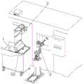
如图1所示,是本发明的自动上料装置,包括阶梯上料机1、3D识别装置2和对识别后的物料进行自动抓取挪移的机械手3。阶梯上料机1的物料逐级阶梯状地上料以输送物料到上方位置。本发明中,阶梯上料机1输送物料,本发明输送的物料尤其适用于棒状的物料,当然也可以输送其他形状的物料,阶梯上料机1输送物料到上方位置后,3D识别装置2通过视觉识别识别出物料的方位和物料形态信息,并将信息传输给机械手3,机械手3按照物料信息进行抓取挪移。As shown in FIG. 1 , it is an automatic feeding device of the present invention, including a step feeding machine 1 , a
如图1~图6所示,本发明的阶梯上料机1包括:多列位置依次增高的移动部11、依次穿插在移动部11内的固定不动的固定部和将机械手3抓取不到或不利于抓取的物料进行剔除并使被剔除的物料继续回流到初始位置的剔除机构4;多列移动部11在一驱动装置6驱动下同时上下移动地输送物料、固定部用于接紧邻的移动部11所输送的物料,固定部是固定不动的;如图2~图6所示,多列移动部11和固定部的顶端是向输料方向倾斜的斜面,当然本发明还可以用使多列移动部11和固定部自身倾斜设置的方法达到上述目的。其中,移动部11的列数常用的是2~5列,固定部的列数常用的亦是2~5列,本发明中优选的列数是2~5列,当然也可以将移动部11固定部交错排布多列,但排布的列数越多,移动部11和固定部的结构越庞大,为了使输送高度或者输送效率提高还可以采用增大移动部11固定部每列的高度或长度的方式实现。As shown in FIGS. 1 to 6 , the step loader 1 of the present invention includes: a plurality of rows of moving
如图1~图6所示,本发明中,移动部11上下移动地输送物料到固定部上,多列移动部11和多列固定部交叉排布。如图5~图6所示,图5是驱动装置6驱动多列移动部11整体下移,此时物料从固定部(未打阴影的多列是固定部)落到移动部11上,其中的移动部11和固定部都向输料方向倾斜以利于物料落下,图6中移动部11上的物料被驱动装置6驱动上移后,直到移动部11顶端高度高于相邻的固定部高度才停止移动,移动部11上的物料落到固定部上,采用此种方式将物料输送到固定部最高位置处。如图5~图6所示,移动部11的左侧紧邻的是用于暂时存储物料的存料部51,存料部51是倾斜的,以方便物料自动滚落或滑落到移动部11上。本发明中,当有物料中途掉落时会掉落到存料部51内以继续参与下一次的上料。As shown in FIG. 1 to FIG. 6 , in the present invention, the moving
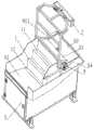
如图1~图4所示,阶梯上料机1和3D识别装置2集成在一架体5上。本发明中,机械手3不在架体5上。As shown in FIG. 1 to FIG. 4 , the step feeder 1 and the
如图2~图4所示,阶梯上料机1还包括用于接被移动部11输送到固定部预定高度处的物料的接料部52、将接料部52与固定部预定高度处连接起来以使物料滑移下落的第一滑移部53,3D识别装置2对接料部52内的物料进行识别。本发明中,第一滑移部53倾斜设置使物料滑下到接料部52内,3D识别装置2对准接料部52的区域对物料进行识别。As shown in FIGS. 2 to 4 , the step feeding machine 1 further includes a
如图2~图4所示,阶梯上料机1还包括连接接料部52和存料部51,以使被剔除机构4剔除的物料从接料部52回流到存料部51的第二滑移部54。本发明中,第二滑移部54也倾斜设置,方向向存料部51倾斜,以方便物料自动滑落或滚落。As shown in FIGS. 2 to 4 , the step feeding machine 1 further includes a connecting
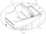
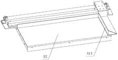
如图2~图4和图7~图8所示,剔除机构4包括:设置在架体5上第一滑移部53的下方与第一滑移部53物料下滑方向垂直的位于水平方向上的轨道55、与轨道55配合并在轨道55上滑移的滑动件41、与滑动件41固定连接且向远离轨道55的一侧延伸并紧贴接料部52的上表面用于推移物料到第二滑移部54内的推板411。本发明中推板411的延伸方向与轨道55垂直。As shown in Figures 2 to 4 and Figures 7 to 8, the rejecting
如图2~图4和图7~图8所示,本发明中,机械手3抓取不到或不利于抓取的物料由剔除机构4将其剔除经由第二滑移部54到存料部51继续参与下一次的上料输料。As shown in FIGS. 2 to 4 and 7 to 8 , in the present invention, the materials that cannot be grasped by the manipulator 3 or are unfavorable for grasping are removed by the rejecting
本发明中,推板411沿轨道55移动,当推板411沿轨道55向靠近第二滑移部54滑移时,接料部52上的物料被推板411推移到第二滑移部54,第二滑移部54是倾斜的,第二滑移部54内的物料自动滚落或滑落到存料部51内参与下一次上料循环。In the present invention, the
本发明中,阶梯上料机1还包括用于引导移动部11的移动轨迹使移动部11的移动轨迹不偏移不被卡阻的导向件;导向件包括设置在移动部11上的凹槽和与凹槽相配合地固定在架体5上的凸起的凸轨。本发明中,移动部11在驱动装置6的驱动下上下移动,为了使移动部11的移动轨迹有保证使移动部11不发生倾斜和卡阻,的导向件还可以是在移动部11上设置凸槽,在架体5上设置与凸槽相配合的凹轨的方式实现。当然本附图中未显示此凸轨或凹槽。In the present invention, the step loader 1 further includes a guide member for guiding the movement track of the moving
如图1~图3所示,3D识别装置2的识别范围包括物料的具体位置和物料的具体结构。As shown in Figures 1 to 3, the recognition range of the
如图1~图3所示,3D识别装置2是采用被动算法的双目立体视觉算法对物料进行视觉识别。本发明中的3D视觉识别装置采用双目立体视觉算法,此算法过程与人类视觉感知过程类似;3D视觉识别装置采用双目立体视觉算法,计算来自多只相机的深度信息,利用两只相机的校准信息,生成深度图像,提供了更加丰富的数据来识别物料的各种形态,以引导机械手3的运动和响应。As shown in Figures 1 to 3, the
如图1~图8所示,本发明按照如下动作流程进行自动上料:As shown in Figures 1 to 8, the present invention performs automatic feeding according to the following action flow:
阶梯上料机1动作将物料输送到固定部预定高度处位置,物料在固定部预定高度处顺着倾斜的第一滑移部53滚落或滑落到接料部52上,位于接料部52上方的3D识别装置2对物料进行3D视觉识别并将位置和状态信息传输给机械手3,由机械手3进行自动抓取,当接料部52上的物料不利于机械手3抓取时,剔除机构4动作将物料推移至第二滑移部54内并再继续回到初始位置即回到存料部51内继续参与下一次自动上料循环。The action of step loader 1 transports the material to the position at the predetermined height of the fixed part, and the material rolls down or slides down to the receiving
Claims (10)
Priority Applications (1)
| Application Number | Priority Date | Filing Date | Title |
|---|---|---|---|
| CN202010823380.4ACN112059687A (en) | 2020-08-17 | 2020-08-17 | Automatic feeding device |
Applications Claiming Priority (1)
| Application Number | Priority Date | Filing Date | Title |
|---|---|---|---|
| CN202010823380.4ACN112059687A (en) | 2020-08-17 | 2020-08-17 | Automatic feeding device |
Publications (1)
| Publication Number | Publication Date |
|---|---|
| CN112059687Atrue CN112059687A (en) | 2020-12-11 |
Family
ID=73661908
Family Applications (1)
| Application Number | Title | Priority Date | Filing Date |
|---|---|---|---|
| CN202010823380.4APendingCN112059687A (en) | 2020-08-17 | 2020-08-17 | Automatic feeding device |
Country Status (1)
| Country | Link |
|---|---|
| CN (1) | CN112059687A (en) |
Cited By (2)
| Publication number | Priority date | Publication date | Assignee | Title |
|---|---|---|---|---|
| CN112247641A (en)* | 2020-09-30 | 2021-01-22 | 芜湖锐冠智能装备有限公司 | Automatic feeding system |
| CN120001666A (en)* | 2025-04-16 | 2025-05-16 | 湖南农业大学 | Seed intelligent screening system |
Citations (6)
| Publication number | Priority date | Publication date | Assignee | Title |
|---|---|---|---|---|
| DE102014226384A1 (en)* | 2014-12-18 | 2016-06-23 | Sms Group Gmbh | Charging system and charging process for forging machines |
| CN106144514A (en)* | 2016-07-27 | 2016-11-23 | 重庆秋田齿轮有限责任公司 | A kind of bar transmission system |
| CN206827555U (en)* | 2017-03-15 | 2018-01-02 | 爱汽科技(佛山)有限公司 | A kind of bar automatic charging device |
| CN208292236U (en)* | 2018-05-21 | 2018-12-28 | 广东科捷龙机器人有限公司 | Manipulator based on Machine Vision Recognition grabs assembly equipment |
| CN110899141A (en)* | 2019-12-10 | 2020-03-24 | 广东华特气体股份有限公司 | Gas bomb weighing and defective product removing machine |
| CN212635135U (en)* | 2020-08-17 | 2021-03-02 | 芜湖锐冠智能装备有限公司 | Automatic feeding device |
- 2020
- 2020-08-17CNCN202010823380.4Apatent/CN112059687A/enactivePending
Patent Citations (6)
| Publication number | Priority date | Publication date | Assignee | Title |
|---|---|---|---|---|
| DE102014226384A1 (en)* | 2014-12-18 | 2016-06-23 | Sms Group Gmbh | Charging system and charging process for forging machines |
| CN106144514A (en)* | 2016-07-27 | 2016-11-23 | 重庆秋田齿轮有限责任公司 | A kind of bar transmission system |
| CN206827555U (en)* | 2017-03-15 | 2018-01-02 | 爱汽科技(佛山)有限公司 | A kind of bar automatic charging device |
| CN208292236U (en)* | 2018-05-21 | 2018-12-28 | 广东科捷龙机器人有限公司 | Manipulator based on Machine Vision Recognition grabs assembly equipment |
| CN110899141A (en)* | 2019-12-10 | 2020-03-24 | 广东华特气体股份有限公司 | Gas bomb weighing and defective product removing machine |
| CN212635135U (en)* | 2020-08-17 | 2021-03-02 | 芜湖锐冠智能装备有限公司 | Automatic feeding device |
Cited By (3)
| Publication number | Priority date | Publication date | Assignee | Title |
|---|---|---|---|---|
| CN112247641A (en)* | 2020-09-30 | 2021-01-22 | 芜湖锐冠智能装备有限公司 | Automatic feeding system |
| CN120001666A (en)* | 2025-04-16 | 2025-05-16 | 湖南农业大学 | Seed intelligent screening system |
| CN120001666B (en)* | 2025-04-16 | 2025-07-25 | 湖南农业大学 | Seed intelligent screening system |
Similar Documents
| Publication | Publication Date | Title |
|---|---|---|
| CN112059687A (en) | Automatic feeding device | |
| DE202016002239U1 (en) | Product feeding apparatus | |
| CN110759054A (en) | A piston rod feeding conveyor line | |
| CN203612592U (en) | Automatic feeding system and automatic assembling system | |
| EP3388374B1 (en) | Drop batch builder technology | |
| CN212635135U (en) | Automatic feeding device | |
| CN110961935B (en) | Steel pipe processing integrated equipment, control system and control method | |
| CN210655225U (en) | Unordered grabbing device of robot based on 3D camera | |
| CN109292333B (en) | automatic mail access system | |
| JP2013516370A (en) | Apparatus and method for forming a group of boxed products | |
| CN105600490A (en) | Explosive loading method and explosive loading device | |
| CN108405691A (en) | A kind of automatic loading/unloading stamping line | |
| CN112660830B (en) | Wood board sorting bin, system and method | |
| CN109677951A (en) | A kind of the bin type feed system and method for adjust automatically workpiece posture | |
| CN209113095U (en) | A kind of chip feeding device of burning chip equipment | |
| CN214186289U (en) | Automatic feeding system | |
| KR101663934B1 (en) | Automatic sorting and feeding device | |
| EP0043403A1 (en) | Device for arranged transfer of successively advanced objects or groups of objects | |
| CN211732982U (en) | Automatic reason material system of magnetic core product | |
| JP6923424B2 (en) | Tableware organizer and how to organize tableware | |
| CN207293540U (en) | The automatic blanking mechanism of rod-like piece | |
| CN202296343U (en) | Common rail transverse moving mechanism | |
| CN216026291U (en) | Double-row conveying sliding table type sorting equipment | |
| CN112247641A (en) | Automatic feeding system | |
| CN215362076U (en) | Cup separating device |
Legal Events
| Date | Code | Title | Description |
|---|---|---|---|
| PB01 | Publication | ||
| PB01 | Publication | ||
| SE01 | Entry into force of request for substantive examination | ||
| SE01 | Entry into force of request for substantive examination | ||
| RJ01 | Rejection of invention patent application after publication | ||
| RJ01 | Rejection of invention patent application after publication | Application publication date:20201211 |