CN112050002A - A pipe socket structure - Google Patents
A pipe socket structureDownload PDFInfo
- Publication number
- CN112050002A CN112050002ACN202011037771.XACN202011037771ACN112050002ACN 112050002 ACN112050002 ACN 112050002ACN 202011037771 ACN202011037771 ACN 202011037771ACN 112050002 ACN112050002 ACN 112050002A
- Authority
- CN
- China
- Prior art keywords
- socket
- section
- socket section
- spherical
- convex surface
- Prior art date
- Legal status (The legal status is an assumption and is not a legal conclusion. Google has not performed a legal analysis and makes no representation as to the accuracy of the status listed.)
- Pending
Links
- 238000007789sealingMethods0.000claimsdescription43
- 210000005056cell bodyAnatomy0.000claims7
- 238000010030laminatingMethods0.000claims1
- 239000000463materialSubstances0.000description17
- 239000002689soilSubstances0.000description5
- 238000000926separation methodMethods0.000description4
- 229910000831SteelInorganic materials0.000description3
- 239000000178monomerSubstances0.000description3
- 239000010959steelSubstances0.000description3
- 230000000903blocking effectEffects0.000description2
- 238000010586diagramMethods0.000description2
- 230000000694effectsEffects0.000description2
- 238000000034methodMethods0.000description2
- 230000007812deficiencyEffects0.000description1
- 230000007613environmental effectEffects0.000description1
- 239000012530fluidSubstances0.000description1
- 238000012986modificationMethods0.000description1
- 230000004048modificationEffects0.000description1
Images


Classifications
- F—MECHANICAL ENGINEERING; LIGHTING; HEATING; WEAPONS; BLASTING
- F16—ENGINEERING ELEMENTS AND UNITS; GENERAL MEASURES FOR PRODUCING AND MAINTAINING EFFECTIVE FUNCTIONING OF MACHINES OR INSTALLATIONS; THERMAL INSULATION IN GENERAL
- F16L—PIPES; JOINTS OR FITTINGS FOR PIPES; SUPPORTS FOR PIPES, CABLES OR PROTECTIVE TUBING; MEANS FOR THERMAL INSULATION IN GENERAL
- F16L27/00—Adjustable joints; Joints allowing movement
- F16L27/02—Universal joints, i.e. with mechanical connection allowing angular movement or adjustment of the axes of the parts in any direction
- F16L27/04—Universal joints, i.e. with mechanical connection allowing angular movement or adjustment of the axes of the parts in any direction with partly-spherical engaging surfaces
- F16L27/06—Universal joints, i.e. with mechanical connection allowing angular movement or adjustment of the axes of the parts in any direction with partly-spherical engaging surfaces with special sealing means between the engaging surfaces
- F16L27/067—Universal joints, i.e. with mechanical connection allowing angular movement or adjustment of the axes of the parts in any direction with partly-spherical engaging surfaces with special sealing means between the engaging surfaces the sealing means being actuated by the medium pressure
- F—MECHANICAL ENGINEERING; LIGHTING; HEATING; WEAPONS; BLASTING
- F16—ENGINEERING ELEMENTS AND UNITS; GENERAL MEASURES FOR PRODUCING AND MAINTAINING EFFECTIVE FUNCTIONING OF MACHINES OR INSTALLATIONS; THERMAL INSULATION IN GENERAL
- F16L—PIPES; JOINTS OR FITTINGS FOR PIPES; SUPPORTS FOR PIPES, CABLES OR PROTECTIVE TUBING; MEANS FOR THERMAL INSULATION IN GENERAL
- F16L27/00—Adjustable joints; Joints allowing movement
- F16L27/02—Universal joints, i.e. with mechanical connection allowing angular movement or adjustment of the axes of the parts in any direction
- F16L27/023—Universal and rotating joints
Landscapes
- Engineering & Computer Science (AREA)
- General Engineering & Computer Science (AREA)
- Mechanical Engineering (AREA)
- Joints Allowing Movement (AREA)
Abstract
Description
Translated fromChinese【技术领域】【Technical field】
本发明涉及管材领域,具体涉及一种管道承插口结构。The invention relates to the field of pipes, in particular to a pipe socket structure.
【背景技术】【Background technique】
管道由多个管材单体连接而成,管材单体的一端是插口段,另一端是承口段,把管材单体的插口段插入另一管材单体的承口段内,如此类推将若干个管材单体连接成管道,当管道被铺设在土层中之后,各个管材单体相互抵靠使得它们难以横向移动,但是,当发生地质沉降等土层变形现象时,土层的变形导致管道周围受到挤压力从而导致管材单体之间转动,各个管材单体之间不再相互靠紧,管材单体之间的连接处容易出现间隙,甚至使得相邻的两个管材单体脱离。The pipeline is formed by connecting a plurality of single pipe materials. One end of the single pipe material is a socket section, and the other end is a socket section. Insert the socket section of a single pipe material into the socket section of another pipe material, and so on. The individual pipe materials are connected to form a pipeline. After the pipeline is laid in the soil layer, the individual pipe materials abut against each other, making it difficult for them to move laterally. However, when the soil layer deformation such as geological subsidence occurs, the deformation of the soil layer causes the pipeline The surrounding squeeze force will cause the rotation of the pipe units, the individual pipe units will no longer be in close contact with each other, and the connection between the pipe units is prone to gaps, and even two adjacent pipe units may be separated.
尤其是钢管等硬质材料制成的管材,管材单体本身难以发生形变,管道变形容易使得相邻的两个管材单体之间在二者的连接处,即承插口处分离,所以传统的钢管在承插口处一般预留有间隙,使得相邻的管材单体之间能够轻微转动,然而管材单体预留间隙会导致管道的密封性下降,容易导致管内流体泄露,而且,一旦相邻的管材单体之间转动就使得二者连接处间隙更加大,甚至使得二者脱离。Especially for pipes made of hard materials such as steel pipes, the single pipe itself is difficult to deform, and the deformation of the pipe is easy to cause separation between the two adjacent pipe elements at the connection between the two, that is, the socket and socket, so the traditional Generally, a gap is reserved at the socket and socket of the steel pipe, so that the adjacent pipe materials can rotate slightly. However, the reserved gap of the pipe material will reduce the sealing performance of the pipeline and easily lead to the leakage of fluid in the pipe. The rotation between the two pipe monomers makes the gap between the two joints larger, and even makes the two separate.
因此在钢管的承插口结构上,如何保证管材单体之间保证密封性的同时保留管材单体与管材单体之间转动能力是行业内一直渴求解决的技术问题。Therefore, on the socket and socket structure of the steel pipe, how to ensure the tightness between the pipe units while retaining the rotation ability between the pipe unit and the pipe unit is a technical problem that the industry has been eager to solve.
【发明内容】[Content of the invention]
本发明目的是克服了现有技术的不足,提供一种密封性好,且能够在土层变形的时候防止相邻的管材单体之间脱离的承插口结构。The purpose of the present invention is to overcome the deficiencies of the prior art, and to provide a socket-socket structure with good sealing performance and capable of preventing the separation of adjacent pipe materials when the soil layer is deformed.
本发明是通过以下技术方案实现的:The present invention is achieved through the following technical solutions:
一种管道承插口结构,包括能够插接在一起的插口段和承口段,所述的承口段的内侧壁上设置有承口配合部,所述的插口段的外侧壁上设置有插口配合部,所述的承口配合部与插口配合部相互配合以使得插口段能够相对承口段转动,所述的插口段和承口段之间设有能够在插口段相对承口段转动后限制二者脱离的自铆结构。A pipe socket and socket structure, comprising a socket section and a socket section that can be inserted together, the inner side wall of the socket section is provided with a socket matching portion, and the outer side wall of the socket section is provided with a socket A matching part, the socket matching part and the socket matching part cooperate with each other so that the socket section can rotate relative to the socket section, and a socket section is provided between the socket section and the socket section that can rotate relative to the socket section after the socket section is rotated relative to the socket section. A self-riveting structure that limits the separation of the two.
如上所述的管道承插口结构,所述的承口配合部为设置在承口段上的第一球形凹面,所述的插口配合部位为设置在插口段,当插口段插入承口段时第一球形凸面抵靠在第一球形凹面上而使得插口段能够相对承口段转动。In the pipe socket and socket structure described above, the socket fitting part is the first spherical concave surface arranged on the socket section, the socket fitting part is arranged on the socket section, and the first socket section is inserted when the socket section is inserted into the socket section. A spherical convex surface abuts against the first spherical concave surface so that the socket segment can rotate relative to the socket segment.
如上所述的管道承插口结构,所述承口段的左端开口且插口段通过承口段的左端口插入承口段内部,所述的环形凸起设置在第一球形凸面右侧,所述的槽体右侧壁上设置有与第一球形凹面共球心的第二球形凹面,所述的环形凸起右侧设置有与第二球形凹面相贴合的第二球形凸面,所述槽体左侧壁与环形凸起之间留有供插口段相对承口段转动的空间。In the pipe socket and socket structure described above, the left end of the socket section is open and the socket section is inserted into the socket section through the left port of the socket section, the annular protrusion is arranged on the right side of the first spherical convex surface, and the The right side wall of the groove body is provided with a second spherical concave surface with the same spherical center as the first spherical concave surface, the right side of the annular protrusion is provided with a second spherical convex surface that fits with the second spherical concave surface, the groove A space for the socket section to rotate relative to the socket section is left between the left side wall of the body and the annular protrusion.
如上所述的管道承插口结构,所述的环形凸起截面为齿状,所述的槽体的截面形状与环形凸起的形状一致,所述的环形凸起左侧面在插口段相对承口段转动设定角度后与槽体的左侧壁贴合,使得在插口段相对承口段转动时环形凸起与槽体相咬合。In the above-mentioned pipe socket and socket structure, the cross-section of the annular protrusion is tooth-shaped, the cross-sectional shape of the groove body is consistent with the shape of the annular protrusion, and the left side of the annular protrusion is opposite to the socket in the socket section. After the mouth section is rotated to a set angle, it is attached to the left side wall of the groove body, so that the annular protrusion is engaged with the groove body when the socket section rotates relative to the socket section.
如上所述的管道承插口结构,所述的第一球形凹面和第一球形凸面之间设置有密封结构。In the pipe socket structure described above, a sealing structure is provided between the first spherical concave surface and the first spherical convex surface.
如上所述的管道承插口结构,在所述插口段上并在第一球形凸面左侧设置有辅助环形凸起,在所述的承口段上并在辅助环形凸起相应的位置上设置有辅助槽体,当插口段相对承口段转动时辅助环形凸起部分陷入辅助槽体之中从而阻止插口段相对承口段横向移动而脱出。The above-mentioned pipe socket and socket structure, on the socket section and on the left side of the first spherical convex surface is provided with an auxiliary annular protrusion, on the socket section and on the corresponding position of the auxiliary annular protrusion is provided with. The auxiliary groove body, when the socket segment rotates relative to the socket segment, the auxiliary annular convex part sinks into the auxiliary groove body to prevent the socket segment from moving laterally relative to the socket segment to escape.
如上所述的管道承插口结构,所述的密封结构包括设置在所述插口段上并位于第一球形凸面位置上的密封圈,在所述插口段上并位于第一球形凸面右侧设置有低于第一球形凸面的平壁段,所述的密封圈套设在平壁段外侧壁上,在所述密封圈右侧设置有用于将密封圈向左压向插口段的固定环。The pipe socket and socket structure as described above, the sealing structure includes a sealing ring arranged on the socket section and located on the first spherical convex surface, and on the socket section and located on the right side of the first spherical convex surface is provided with a sealing ring. Below the flat wall section of the first spherical convex surface, the sealing ring is sleeved on the outer side wall of the flat wall section, and a fixing ring is arranged on the right side of the sealing ring for pressing the sealing ring to the left toward the socket section.
如上所述的管道承插口结构,所述的密封圈的外侧表面以及固定环的外侧表面和第一球形凸面位于大致同一球面上。In the above-mentioned pipe socket structure, the outer surface of the sealing ring and the outer surface of the fixing ring and the first spherical convex surface are located on substantially the same spherical surface.
如上所述的管道承插口结构,所述的密封结构包括设置在承口段内侧壁上的密封环,第一球形凹面设置在密封环上。In the above-mentioned pipe socket structure, the sealing structure includes a sealing ring arranged on the inner side wall of the socket section, and the first spherical concave surface is arranged on the sealing ring.
与现有技术相比,本发明有如下优点:Compared with the prior art, the present invention has the following advantages:
1、本发明的承插口结构通过插口段的第一球形凸面与承口段的第一球形凹面相抵靠使得插口段能够相对承口段转动,这样使得相邻的管材单体能够相互转动并且在二者转动时第一球形凸面与第一球形凹面始终保持贴合,保证承插口结构的密封性,自铆结构可以在管道发生变形的时候防止相邻的两个管材单体之间横向移动而脱离。1. The socket and socket structure of the present invention allows the socket section to rotate relative to the socket section by abutting the first spherical convex surface of the socket section with the first spherical concave surface of the socket section, so that the adjacent pipe materials can rotate with each other and in When the two are rotated, the first spherical convex surface and the first spherical concave surface are always kept in contact to ensure the sealing of the socket and socket structure. break away.
2、本发明的自铆结构插口段上的环形凸起和设置承口段上的槽体,环形凸起和槽体位置相对应并且设置在第一球形凸面的一侧,当承口段与插口段发生转动时,二者绕着第一球形凸面的球心位置转动,这样环形凸起跟着绕该球心转动从而使得环形凸部分起进入槽体中,从而阻挡插口段相对承口段横向移动而脱出。2. The annular protrusion on the socket section of the self-riveting structure of the present invention and the groove body on the socket section are arranged. The annular protrusion and the groove body correspond in position and are arranged on one side of the first spherical convex surface. When the socket segment rotates, the two rotate around the center of the first spherical convex surface, so that the annular protrusion rotates around the center of the sphere so that the annular convex part rises into the groove body, thereby blocking the transverse direction of the socket segment relative to the socket segment. move out.
3、本发明的环形凸起右侧设置有与第二球形凹面相贴合的第二球形凸面,当承口段与插口段发生转动时第二球形凸面与第二球形凹面始终能够保持贴合,保证密封性。3. The right side of the annular protrusion of the present invention is provided with a second spherical convex surface that fits with the second spherical concave surface. When the socket segment and the socket segment rotate, the second spherical convex surface and the second spherical concave surface can always be kept in contact with each other. , to ensure tightness.
【附图说明】【Description of drawings】
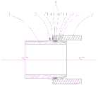
图1是本发明的实施例一的承插口结构的横截面图;Fig. 1 is the cross-sectional view of the socket structure of the first embodiment of the present invention;
图2是本发明的实施例一的管道的横截面图;FIG. 2 is a cross-sectional view of the pipeline according to the first embodiment of the present invention;
图3是本发明实施例的实施例一当管道发生转动时的示意图;FIG. 3 is a schematic diagram of
图4是本发明实施例的实施例二的承插口结构的横截面图;4 is a cross-sectional view of the socket structure of the second embodiment of the present invention;
图5是本发明实施例的实施例三的承插口结构的横截面图;5 is a cross-sectional view of the socket structure of the third embodiment of the present invention;
图6是图5的局部放大图;Fig. 6 is a partial enlarged view of Fig. 5;
图7是本发明实施例的实施例四的承插口结构的横截面图;7 is a cross-sectional view of the socket structure of the fourth embodiment of the present invention;
图8是本发明实施例的实施例一的承口配合部和插口配合部的示意图;8 is a schematic diagram of the socket fitting portion and the socket fitting portion of the first embodiment of the present invention;
【具体实施方式】【Detailed ways】
下面结合附图对本发明作进一步描述:The present invention will be further described below in conjunction with the accompanying drawings:
实施例一:Example 1:
如图1和2所示,管材单体的两头分别设置有插口段1和承口段2,插口段1和承口段2相插接在一起从而将两个管材单体相连接,所述的承口段2的内侧壁上设有第一球形凹面21,所述的插口段1上设有与所述的第一球形凹面21相匹配的第一球形凸面11,当插口段1插入承口段2时第一球形凸面11抵靠在第一球形凹面21上,使得相邻的管材单体能够转动并且在二者转动时第一球形凸面11与第一球形凹面21始终保持贴合,保证承插口结构的密封性,自铆结构可以在管道发生变形的时候防止相邻的两个管材单体之间横向移动而脱离。As shown in Figures 1 and 2, the two ends of the single pipe material are respectively provided with a
另外,作为另一种可选的实施方式,如图8所示,在插口段1或者插口段承口段2设置凸起201,使得插口段1或者插口段承口段2在凸起201处抵靠接触,从而使得二者能够以凸起201为支点转动。In addition, as another optional embodiment, as shown in FIG. 8 , a
更详细地说,自铆结构包括若干个环绕设置在插口段1上并且设置在第一球形凸面11一侧的环形凸起12,以及设置在承口段2上并与环形凸起12相对应的槽体22,当插口段1相对承口段2转动时环形凸起12部分进入槽体22之中从而阻止插口段1相对承口段2横向移动而脱出。如图3所示,因为各个管材单体之间都是相互贴靠压紧的,所以当承口段2与插口段1发生转动时,二者会绕着第一球形凸面11的球心位置P转动,当插口段1相对承口段2顺时针转动时,位于球心位置P下方的部分环形凸起12进入槽体22中,而位于球心位置P上方的部分环形凸起12远离槽体22,如果这时候插口段1向左移动,那么槽体22的左侧槽壁能够阻挡位于球心位置P下方的部分环形凸起12向左移动(此时槽体22的左侧槽壁与环形凸起12的左侧面之间还存在较小的距离,当环形凸起12稍微向左移动之后即能够抵达槽体22的左侧槽壁),从而阻止插口段1相对承口段2横向移动而脱出;当插口段1相对承口段2逆时针转动时同理。In more detail, the self-riveting structure includes a plurality of
更详细地说,如图1所示,承口段2的左端开口且插口段1通过承口段2的左端口插入承口段2内部,环形凸起12设置在第一球形凸面11右侧,所述的槽体22右侧壁上设置有与第一球形凹面21共球心的第二球形凹面221,环形凸起12右侧设置有与第二球形凹面221相贴合的第二球形凸面121,当承口段2与插口段1发生转动时第二球形凸面11与第二球形凹面21始终能够保持贴合,环形凸起12顺着第二球形凹面21滑动而进入槽体22之中,在插口段1相对承口段2发生转动之后插口段1向左移动时,环形凸起12受到槽体22的左侧壁阻挡从而阻止插口段1向左移动而脱离承口段2。所述槽体22左侧壁与环形凸起12之间留有供插口段1相对承口段2转动的空间,如图3所示,该空间大小取决于插口段1和承口段2之间转动的角度α的大小,可根据管材需要转动的角度以及管材周边环境形变量大小来设计可转动的角度α。In more detail, as shown in FIG. 1 , the left end of the
优选地,所述的环形凸起12左侧面在插口段1相对承口段2转动设定角度α后与槽体22的左侧壁贴合,使得在插口段1相对承口段2转动时环形凸起12与槽体22相咬合,因为管材单体与管材单体之间是相互贴靠压紧的,所以管道变形时优先导致管材单体之间转动,当相邻的两个管材单体转动至设定角度α后,环形凸起12与槽体22相咬合使得两个管材单体不再转动,同时使得二者相互铆合,阻止二者脱离,这样即使土层在相同方向发生更大的变形也不会使管道变形或者管材单体之间脱离,同时保证管材单体之间的密封性。Preferably, the left side of the
实施例二:Embodiment 2:
如图4所示,一种管道承插口结构,与实施例一不同之处在于,所述的第一球形凹面21和第一球形凸面11之间设置有密封结构4,增强第一球形凹面21和第一球形凸面11之间的密封效果。As shown in FIG. 4 , a pipe socket structure is different from the first embodiment in that a sealing structure 4 is provided between the first spherical
优选地,所述的密封结构4包括设置在所述插口段1上并位于第一球形凸面11位置上的密封圈41,所述密封圈41的外侧表面为与所述第一球形凸面11共球心的球形凸面,在插口段1和承口段2相平齐的时候,该球形凸面和第一球形凹面21相贴合设置,使得插口段1和承口段2转动的时候第一球形凹面21始终能够贴靠密封圈41,保证其密封效果。Preferably, the sealing structure 4 includes a sealing
优选地,在所述插口段1上并位于第一球形凸面11右侧设置有低于第一球形凸面11的平壁段13,所述的密封圈41套设在平壁段外侧壁上,在所述密封圈41右侧设置有用于将密封圈41向左压向插口段1的固定环42。Preferably, a
优选地,所述的密封圈41的外侧表面以及固定环42的外侧表面和第一球形凸面11位于大致同一球面上,第一球形凹面21与插口段1接触的面积更大,保证插口段1和承口段2之间转动平顺以及插口段1和承口段2之间的密封性。Preferably, the outer surface of the sealing
优选地,所述的固定环42通过螺栓从固定环42左侧朝向右侧连接在插口段1上,使得固定环42和插口段1将密封圈41加紧固定在插口段1上,这样便于在插口段1安装密封圈41和固定环42,另外这样使得密封圈41被压紧不容易因为摩擦而松动。Preferably, the fixing
实施例三:Embodiment three:
一种管道承插口结构,与实施例二不同之处在于,如图3所示,承口段2与插口段1发生转动时,二者会绕着第一球形凸面11的球心位置P转动,当插口段1相对承口段2顺时针转动时,位于球心位置P下方的部分环形凸起12进入槽体22中,而位于球心位置P上方的部分环形凸起12远离槽体22,如果这时候插口段1向左移动,那么只有位于球心位置P下方的部分环形凸起12受到槽体22的阻挡,而位于球心位置P上方的环形凸起12则不受到槽体22的阻挡。A pipe socket structure, which is different from the second embodiment is that, as shown in FIG. 3 , when the
为了解决上述这种受力不均的问题,本实施例提供一种管道承插口结构,与实施例二不同之处在于:In order to solve the above-mentioned problem of uneven force, this embodiment provides a pipe socket structure, which is different from the second embodiment in that:
在所述插口段1上并在第一球形凸面11左侧设置有辅助环形凸起12,在所述的承口段2上并在辅助环形凸起14相应的位置上设置有辅助槽体23,当插口段1相对承口段2转动时辅助环形凸起14部分陷入辅助槽体23之中从而阻止插口段1相对承口段2横向移动而脱出,这样当位于球心位置P上方或者下方的部分环形凸起12远离槽体22的时候,正好位于球心位置P相反一侧的部分辅助环形凸起14进入辅助槽体23之中,使得插口段1位于球心位置P的上方的部分和位于球心位置P下方的部分均能够受到承口段2的阻力,使得插口段1能够受到阻止其脱离承口段2的阻力,并且受到的阻力更加均匀。An auxiliary
实施例四:Embodiment 4:
一种管道承插口结构,与实施例二不同之处在于,如图7所示,所述的密封结构4包括设置在承口段2内侧壁上的密封环43,第一球形凹面21设置在密封环43上,这样便于加工第一球形凹面21以及将密封环43安装在承口段2上,另外,这样可以使得密封环43与插口段1之间的接触面积较大,保证较好的密封性。A pipe socket structure is different from the second embodiment in that, as shown in FIG. 7 , the sealing structure 4 includes a sealing ring 43 arranged on the inner side wall of the
以上所述的仅是本发明的实施例,方案中公知的具体结构及特性等常识在此未作过多描述。应当指出,对于本领域的技术人员来说,在不脱离本发明结构的前提下,还可以作出若干变形和改进,这些也应该视为本发明的保护范围,这些都不会影响本发明实施的效果和专利的实用性。本申请要求的保护范围应当以其权利要求的内容为准,说明书中的具体实施方式等记载可以用于解释权利要求的内容。The above descriptions are only examples of the present invention, and common knowledge such as well-known specific structures and characteristics in the solution are not described too much here. It should be pointed out that for those skilled in the art, on the premise of not departing from the structure of the present invention, several modifications and improvements can also be made, which should also be regarded as the protection scope of the present invention, and these will not affect the implementation of the present invention. Effectiveness and utility of patents. The scope of protection claimed in this application shall be based on the content of the claims, and the descriptions of the specific implementation manners in the description can be used to interpret the content of the claims.
Claims (10)
Priority Applications (1)
| Application Number | Priority Date | Filing Date | Title |
|---|---|---|---|
| CN202011037771.XACN112050002A (en) | 2020-09-28 | 2020-09-28 | A pipe socket structure |
Applications Claiming Priority (1)
| Application Number | Priority Date | Filing Date | Title |
|---|---|---|---|
| CN202011037771.XACN112050002A (en) | 2020-09-28 | 2020-09-28 | A pipe socket structure |
Publications (1)
| Publication Number | Publication Date |
|---|---|
| CN112050002Atrue CN112050002A (en) | 2020-12-08 |
Family
ID=73605934
Family Applications (1)
| Application Number | Title | Priority Date | Filing Date |
|---|---|---|---|
| CN202011037771.XAPendingCN112050002A (en) | 2020-09-28 | 2020-09-28 | A pipe socket structure |
Country Status (1)
| Country | Link |
|---|---|
| CN (1) | CN112050002A (en) |
Cited By (1)
| Publication number | Priority date | Publication date | Assignee | Title |
|---|---|---|---|---|
| CN115468044A (en)* | 2022-08-18 | 2022-12-13 | 上海乾林建设工程有限公司 | Connecting structure for pressure pipeline installation and connecting method thereof |
Citations (5)
| Publication number | Priority date | Publication date | Assignee | Title |
|---|---|---|---|---|
| EP1657372A2 (en)* | 2004-11-04 | 2006-05-17 | Funke Kunststoffe GmbH | Pipe connector with variable angle |
| CN2797829Y (en)* | 2005-04-08 | 2006-07-19 | 周佰兴 | Ball shaped universal joint |
| KR101317710B1 (en)* | 2012-08-29 | 2013-10-15 | (주)폴리텍 | Adjustable type elbow for the pipelines |
| CN108443627A (en)* | 2018-03-30 | 2018-08-24 | 广东管博管道技术科技有限公司 | A kind of flexible sealing self-locking bell socket |
| CN213018238U (en)* | 2020-09-28 | 2021-04-20 | 广东智慧碧管管道技术科技有限公司 | Pipeline socket structure |
- 2020
- 2020-09-28CNCN202011037771.XApatent/CN112050002A/enactivePending
Patent Citations (5)
| Publication number | Priority date | Publication date | Assignee | Title |
|---|---|---|---|---|
| EP1657372A2 (en)* | 2004-11-04 | 2006-05-17 | Funke Kunststoffe GmbH | Pipe connector with variable angle |
| CN2797829Y (en)* | 2005-04-08 | 2006-07-19 | 周佰兴 | Ball shaped universal joint |
| KR101317710B1 (en)* | 2012-08-29 | 2013-10-15 | (주)폴리텍 | Adjustable type elbow for the pipelines |
| CN108443627A (en)* | 2018-03-30 | 2018-08-24 | 广东管博管道技术科技有限公司 | A kind of flexible sealing self-locking bell socket |
| CN213018238U (en)* | 2020-09-28 | 2021-04-20 | 广东智慧碧管管道技术科技有限公司 | Pipeline socket structure |
Cited By (1)
| Publication number | Priority date | Publication date | Assignee | Title |
|---|---|---|---|---|
| CN115468044A (en)* | 2022-08-18 | 2022-12-13 | 上海乾林建设工程有限公司 | Connecting structure for pressure pipeline installation and connecting method thereof |
Similar Documents
| Publication | Publication Date | Title |
|---|---|---|
| CN103438228B (en) | Self-sealing centerline butterfly valve | |
| CN210950008U (en) | Quick replacement type multi-way valve for water treatment with connector | |
| CN112050002A (en) | A pipe socket structure | |
| CN205716067U (en) | PVC sewer pipe | |
| CN107990078B (en) | Throttling socket joint type pipe joint | |
| NO124517B (en) | ||
| KR20110116920A (en) | Watertight Packing | |
| CN106122639A (en) | A kind of hose connection device | |
| US20050073147A1 (en) | Casing joints | |
| CN207112159U (en) | A kind of wind tube connecting device | |
| CN213018238U (en) | Pipeline socket structure | |
| CN209354639U (en) | sealing ring | |
| CN207921556U (en) | The quick sealing rubber ring of circular hole take over road spigot-and-socket | |
| CN206581955U (en) | A kind of Urban Underground piping lane prefabricated pipe section seam elastic sealing gasket | |
| TWI335968B (en) | Universal pipe joint | |
| CN204127313U (en) | Anticreep seal ring, anti-drop block and comprise the conduit assembly of described seal ring | |
| CN215214795U (en) | Wear-resistant eccentric butterfly valve seat | |
| KR101047503B1 (en) | Branch socket | |
| CN106640152A (en) | Elastic sealing pad for prefabrication pipe section jointing of city underground pipeline corridor | |
| CN208457271U (en) | A kind of one-way pipeline | |
| CN113819332B (en) | Pipeline sealing structure and pipeline assembly | |
| JP2002303387A (en) | Pipe joint | |
| CN104121439A (en) | Soft-hard combined sealing device | |
| CN204004934U (en) | A kind of soft or hard composite seal device | |
| CN206145143U (en) | Self sealss central line butterfly valve valve plate |
Legal Events
| Date | Code | Title | Description |
|---|---|---|---|
| PB01 | Publication | ||
| PB01 | Publication | ||
| SE01 | Entry into force of request for substantive examination | ||
| SE01 | Entry into force of request for substantive examination |