CN112046796A - Passive butt joint structure for aircraft and modular robot - Google Patents
Passive butt joint structure for aircraft and modular robotDownload PDFInfo
- Publication number
- CN112046796A CN112046796ACN202010731833.0ACN202010731833ACN112046796ACN 112046796 ACN112046796 ACN 112046796ACN 202010731833 ACN202010731833 ACN 202010731833ACN 112046796 ACN112046796 ACN 112046796A
- Authority
- CN
- China
- Prior art keywords
- head
- male
- female
- buckle
- female head
- Prior art date
- Legal status (The legal status is an assumption and is not a legal conclusion. Google has not performed a legal analysis and makes no representation as to the accuracy of the status listed.)
- Granted
Links
Images


Classifications
- B—PERFORMING OPERATIONS; TRANSPORTING
- B64—AIRCRAFT; AVIATION; COSMONAUTICS
- B64G—COSMONAUTICS; VEHICLES OR EQUIPMENT THEREFOR
- B64G1/00—Cosmonautic vehicles
- B64G1/22—Parts of, or equipment specially adapted for fitting in or to, cosmonautic vehicles
- B64G1/64—Systems for coupling or separating cosmonautic vehicles or parts thereof, e.g. docking arrangements
- B64G1/646—Docking or rendezvous systems
Landscapes
- Engineering & Computer Science (AREA)
- Remote Sensing (AREA)
- Aviation & Aerospace Engineering (AREA)
- Manipulator (AREA)
- Connection Of Plates (AREA)
Abstract
Description
Translated fromChinese技术领域technical field
本发明属于机械技术领域,具体涉及一种可用于飞行器及模块化机器人的被动对接结构。The invention belongs to the technical field of machinery, and in particular relates to a passive docking structure that can be used for aircraft and modular robots.
背景技术Background technique
空间交会对接技术是建立永久性载人空间站、从事长期空间飞行活动、开展利用空间资源以及实行空间工业化和商业化须解决的一项关键技术。空间对接技术的作用主要体现在三个方面:一是为长期运行的空间设施提供服务,包括物资补给、设备回收、燃料加注和人员轮换;二是空间建筑的在轨建造和运行服务,如组装空间、天线等;三是航天器在轨重构,实现系统优化以降低对运载能力的要求。Space rendezvous and docking technology is a key technology to be solved for establishing permanent manned space station, engaging in long-term space flight activities, developing and utilizing space resources, and implementing space industrialization and commercialization. The role of space docking technology is mainly reflected in three aspects: one is to provide services for long-term operating space facilities, including material supply, equipment recovery, fuel refueling and personnel rotation; the other is the on-orbit construction and operation services of space buildings, such as Assembly space, antennas, etc.; third, spacecraft on-orbit reconstruction to achieve system optimization to reduce the requirements for carrying capacity.
空间对接机构是用来实现航天器之间多次对接、保持连接与可靠分离的复杂机构,现有的空间对接机构多为主动式对接机构,涉及的技术较为复杂。The space docking mechanism is a complex mechanism for realizing multiple docking, maintaining connection and reliable separation between spacecraft. Most of the existing space docking mechanisms are active docking mechanisms, and the technology involved is relatively complex.
未来的空间在轨服务与维护中,可通过空间机器人对航天器进行拼接组装,这样可以利用被动式对接机构进行空间飞行器的拼接。采用被动式对接机构,可以使对接装置的质量更轻,使对接的过程更为简单,简化对接中碰撞与机构运动的分析,从而提高对接的可靠性。In the future space on-orbit service and maintenance, the spacecraft can be spliced and assembled by space robots, so that the passive docking mechanism can be used to splicing the spacecraft. The passive docking mechanism can make the mass of the docking device lighter, make the docking process simpler, simplify the analysis of the collision and the movement of the mechanism in the docking, thereby improving the reliability of the docking.
发明内容SUMMARY OF THE INVENTION
为了简化空间对接结构,提高对接可靠性,本发明提出了一种可用于飞行器及模块化机器人的被动对接结构,用于航天器的对接或模块化机器人的拼接,使其具有可重构性,并可保证拼接过程的可靠与便捷。In order to simplify the space docking structure and improve the docking reliability, the present invention proposes a passive docking structure that can be used for aircraft and modular robots. And can ensure the reliability and convenience of the splicing process.
所述的被动对接结构,包括公头、母头、压簧、压簧挡板、卡扣、限位螺钉、拆卸滑块、公头底座、母头底座。The passive docking structure includes a male head, a female head, a compression spring, a compression spring baffle, a buckle, a limit screw, a dismantling slider, a male head base, and a female head base.
母头通过固定连接的母头头底座,公头通过固定连接的公头头底座,两者分别与待拼接的航天器或机器人模块连接。The female head passes through the fixedly connected female head base, and the male head passes through the fixedly connected male head base, and the two are respectively connected with the spacecraft or robot module to be spliced.
母头表面沿圆周均匀布置六个凹槽,其中三个为减重槽,另外三个为卡扣滑槽,减重槽和卡扣滑槽间隔布置。The surface of the female head is evenly arranged with six grooves along the circumference, three of which are weight-reducing grooves, and the other three are snap-in chutes.
所述的每个卡扣滑槽都包括卡扣,压簧挡板,压簧,限位螺钉和拆卸滑块;Each of the said snap chute includes a snap, a compression spring baffle, a compression spring, a limit screw and a dismantling slider;
具体为:在卡扣滑槽内最前方的外侧设有拆卸滑块,拆卸滑块通过过渡配合安装在母头表面所开的燕尾槽中,并可在外力作用下在燕尾槽内滑动;Specifically: a dismounting slider is arranged on the outermost outer side of the snap chute, the dismounting slider is installed in the dovetail groove opened on the surface of the female head through transition fit, and can slide in the dovetail groove under the action of external force;
拆卸滑块后方为压簧挡板,压簧挡板固定连接在母头上;压簧挡板内侧压有压簧的一端,压簧的另一端压在卡扣外侧,卡扣位于卡扣滑槽内侧最后方,能来回滑动;在压簧挡板中心开有通孔,用于安放限位螺钉,限位螺钉穿过压簧挡板中心的通孔和压簧,与卡扣外侧的螺纹孔紧固连接;The back of the dismantling slider is the compression spring baffle, which is fixedly connected to the female head; the inner side of the compression spring baffle is pressed with one end of the compression spring, and the other end of the compression spring is pressed on the outside of the buckle, and the buckle is located on the buckle slide. The innermost side of the groove can slide back and forth; there is a through hole in the center of the compression spring baffle for placing the limit screw. Hole fastened connection;
所述的公头为具有球面和圆锥面接合的头部,进行拼接时公头逐渐接近母头,触碰到母头开口边缘滑入或直接进入母头内部,公头进入母头内部后,公头的头部先与三个在母头内部环形分布的卡扣上表面相接触,公头继续向下移动,卡扣沿卡扣滑槽被向外推,同时压簧被压缩;当公头完全进入母头后,被压缩的压簧弹回中立位并将三个卡扣弹回,卡扣下表面卡住公头凹槽的下表面,通过公头和卡扣的摩擦自锁实现对接机构锁紧;The male head is a head with a spherical surface and a conical surface. When splicing, the male head gradually approaches the female head, touches the opening edge of the female head and slides into the female head or directly enters the inside of the female head. After the male head enters the inside of the female head, The head of the male head first comes into contact with the upper surfaces of the three circularly distributed buckles inside the female head, the male head continues to move downward, the buckles are pushed outward along the buckle chute, and the compression spring is compressed at the same time; After the head fully enters the female head, the compressed compression spring springs back to the neutral position and the three buckles bounce back. The docking mechanism is locked;
拆卸时,向外拉拔三个限位螺钉,从而带动三个卡扣沿卡扣滑槽向母头外滑动,利用三个拆卸滑块同时卡住限位螺钉的头部,使卡扣与公头的凹槽表面分离并解锁。When dismantling, pull out the three limit screws to drive the three buckles to slide out of the female head along the buckle chute, and use the three dismantling sliders to clamp the head of the limit screws at the same time, so that the buckles are in contact with the female head. The grooved surface of the male head separates and unlocks.
进一步,在母头底座通过螺钉固连强力磁铁,可在对接时吸附公头并能自对准;Further, the strong magnet is fixed on the base of the female head by screws, which can attract the male head and self-align when docking;
进一步,限位螺钉在母头外侧的头部直径大于弹簧挡板的通孔直径,无法穿过弹簧挡板,从而限制卡扣的位置,避免卡扣从母头的滑槽中脱落;Further, the diameter of the head of the limit screw on the outside of the female head is larger than the diameter of the through hole of the spring baffle and cannot pass through the spring baffle, thereby limiting the position of the buckle and preventing the buckle from falling off from the chute of the female head;
进一步所述母头材料为铝合金,公头的材料为合金钢;Further, the material of the female head is aluminum alloy, and the material of the male head is alloy steel;
进一步,所述公头底座和母头底座两侧均有加强筋;Further, there are reinforcing ribs on both sides of the male head base and the female head base;
进一步,母头的开口边缘上侧设为倒角,形成圆锥面与公头的圆锥面配合,减小公头与母头接触时的阻力,增加公头对接时的容差。Further, the upper side of the opening edge of the female head is set to be chamfered, so that the conical surface is matched with the conical surface of the male head, reducing the resistance when the male head is in contact with the female head, and increasing the tolerance when the male head is butted.
本发明的优点在于:The advantages of the present invention are:
1、本发明一种可用于飞行器及模块化机器人的被动对接机构,通过公头与母头对接的方式完成拼接和锁紧,两部分的接触面均为圆锥面与曲面的接触,在对接时可减小阻力,并增加容差;1. The present invention is a passive docking mechanism that can be used for aircraft and modular robots. The splicing and locking are completed through the docking of male and female heads. The contact surfaces of the two parts are the contact between the conical surface and the curved surface. Can reduce resistance and increase tolerance;
2、本发明一种可用于飞行器及模块化机器人的被动对接机构,实现两模块对接后的自锁,解锁力大,不易脱落;2. The present invention is a passive docking mechanism that can be used for aircraft and modular robots, realizes self-locking after the two modules are docked, has a large unlocking force, and is not easy to fall off;
3、本发明一种可用于飞行器及模块化机器人的被动对接机构,母头内的强力磁铁可将公头吸附,在对接时实现自对准的功能;3. The present invention is a passive docking mechanism that can be used for aircraft and modular robots. The strong magnet in the female head can attract the male head to realize the function of self-alignment during docking;
4、本发明一种可用于飞行器及模块化机器人的被动对接机构,容差大、安装便捷、通用性好,可用于各种需要拼接的航天器和模块化机器人。4. The present invention is a passive docking mechanism that can be used for aircraft and modular robots, has large tolerance, convenient installation and good versatility, and can be used for various spacecraft and modular robots that need to be spliced.
附图说明Description of drawings
图1为本发明可用于飞行器及模块化机器人的对接机构完成拼接时的整体结构图;Fig. 1 is the overall structure diagram when the docking mechanism of the present invention can be used for the aircraft and the modular robot to complete the splicing;
图2为本发明可用于飞行器及模块化机器人的对接机构完成拼接时的正视图;Fig. 2 is the front view when the docking mechanism of the present invention can be used for the aircraft and the modular robot to complete the splicing;
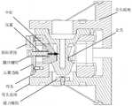
图3为本发明可用于飞行器及模块化机器人的对接机构完成拼接时的横向剖视图;3 is a transverse cross-sectional view of the docking mechanism that can be used for an aircraft and a modular robot according to the present invention when splicing is completed;
图4为本发明可用于飞行器及模块化机器人的对接机构拼接前的剖视图;4 is a cross-sectional view of the docking mechanism that can be used for an aircraft and a modular robot according to the present invention before splicing;
图5为本发明可用于飞行器及模块化机器人的对接机构完成拼接时的纵向剖视图;5 is a longitudinal cross-sectional view of the docking mechanism that can be used for an aircraft and a modular robot according to the present invention when splicing is completed;
图6为本发明可用于飞行器及模块化机器人的对接机构的公头部件结构示意图;FIG. 6 is a schematic structural diagram of a male component of the present invention that can be used in a docking mechanism for an aircraft and a modular robot;
图7为本发明可用于飞行器及模块化机器人的对接机构的母头部件结构示意图。FIG. 7 is a schematic structural diagram of the female head component of the docking mechanism that can be used for an aircraft and a modular robot according to the present invention.
具体实施方式Detailed ways
为了便于本领域普通技术人员理解和实施本发明,下面结合附图对本发明作进一步的详细和深入描述。In order to facilitate the understanding and implementation of the present invention by those of ordinary skill in the art, the present invention will be further described in detail and in-depth below with reference to the accompanying drawings.
本发明提出了一种可用于飞行器及模块化机器人的对接机构,包括公头和母头,通过母头内的三个卡扣在拼接时被压簧弹出,卡入公头的凹槽内,依靠摩擦自锁的结构实现锁紧,母头内的强力磁铁可以在对接时吸附公头,使其有自对准的功能,在不进行解锁的情况下无法用外力将公头与母头分离;本发明是一种可用于两个或多个空间飞行器对接时使用的拼接、锁紧机构,可在飞行器对接时有较大的容差。The invention proposes a docking mechanism that can be used for aircraft and modular robots, which includes a male head and a female head. The three buckles in the female head are ejected by the compression spring during splicing, and are clamped into the groove of the male head. Relying on the frictional self-locking structure to achieve locking, the strong magnet in the female head can attract the male head when docking, so that it has the function of self-alignment, and the male head and the female head cannot be separated by external force without unlocking ; The present invention is a splicing and locking mechanism that can be used when two or more space vehicles are docked, and can have a larger tolerance when the aircraft are docked.
如图1和图2所示,所述的被动对接结构,包括公头、母头、压簧、压簧挡板、卡扣、限位螺钉、拆卸滑块、公头底座和母头底座。As shown in Figures 1 and 2, the passive docking structure includes a male head, a female head, a compression spring, a compression spring baffle, a buckle, a limit screw, a disassembly slider, a male head base and a female head base.
母头材料为铝合金,与母头头底座通过螺钉实现固连,公头材料为合金钢,与公头头底座通过螺钉实现固连,母头和公头分别通过母头底座和公头底座安装在两个需要拼接的航天器或模块中,将需要被拼接的航天器或机器人模块连接在一起,减小其所占据的空间;所述公头底座和母头底座两侧均有加强筋提高其强度;在母头底座中心同时还固定安装强力磁铁,在对接时吸附公头;The material of the female head is aluminum alloy, which is fixed with the base of the female head by screws, and the material of the male head is alloy steel, which is fixed with the base of the male head by screws. In the two spacecraft or modules to be spliced, the spacecraft or robot modules to be spliced are connected together to reduce the space occupied by them; the male base and the female base are provided with reinforcing ribs on both sides to increase their space. Strength; a strong magnet is also fixedly installed in the center of the female head base to attract the male head when docking;
母头表面沿圆周均匀布置六个凹槽,其中三个为减重槽,另外三个为卡扣滑槽,减重槽和卡扣滑槽间隔布置,相邻减重槽中心线与卡扣滑槽中心线间的夹角为60度,相邻的减重槽的中心线形成的夹角为120度,相邻的卡扣滑槽的中心线形成的夹角为120度。The surface of the female head is evenly arranged with six grooves along the circumference, three of which are weight-reducing grooves, and the other three are snap-in chutes. The included angle between the center lines of the chutes is 60 degrees, the included angle formed by the center lines of the adjacent weight reduction grooves is 120 degrees, and the included angle formed by the center lines of the adjacent snap chutes is 120 degrees.
所述的每个卡扣滑槽都包括卡扣,压簧挡板,压簧,限位螺钉和拆卸滑块;Each of the said snap chute includes a snap, a compression spring baffle, a compression spring, a limit screw and a dismantling slider;
其内部结构如图3所示,在卡扣滑槽内最前方的外侧设有拆卸滑块,梯形的拆卸滑块通过过渡配合与母头外部所开的燕尾槽连接,并可在外力作用下在燕尾槽内滑动;Its internal structure is shown in Figure 3. There is a dismantling slider on the outermost outer side of the snap chute. The trapezoidal dismantling slider is connected with the dovetail groove opened on the outside of the female head through transition fit, and can be under the action of external force. Sliding in the dovetail groove;
拆卸滑块后方为压簧挡板,压簧挡板与母头通过螺钉实现固连;压簧挡板内侧压有压簧的一端,压簧的另一端压在卡扣外侧,卡扣位于卡扣滑槽内侧最后方,能来回滑动;当卡扣从母头内部被向外推时压簧被压缩,当外力卸载时压簧会弹回到中立位并将卡扣向母头中心方向推入,限位螺钉可防止卡扣脱落;The back of the dismantling slider is the compression spring baffle, the compression spring baffle and the female head are fixedly connected by screws; the inner side of the compression spring baffle is pressed with one end of the compression spring, the other end of the compression spring is pressed on the outside of the buckle, and the buckle is located in the clip. The innermost side of the buckle chute can slide back and forth; when the buckle is pushed outward from the female head, the pressure spring is compressed, and when the external force is unloaded, the pressure spring will spring back to the neutral position and push the buckle towards the center of the female head Enter, the limit screw can prevent the buckle from falling off;
在压簧挡板中心开有通孔,用于安放限位螺钉,限位螺钉位于拆卸滑块下方,外套压簧,穿过压簧挡板中心的通孔和压簧,与卡扣外侧的螺纹孔紧固连接;限位螺钉在母头外侧的头部直径大于弹簧挡板的中心孔直径,无法穿过弹簧挡板,从而限制卡扣的位置,避免卡扣从母头的滑槽中脱落。There is a through hole in the center of the compression spring baffle for placing the limit screw. The limit screw is located under the dismantling slider, and the compression spring is covered. The through hole and the compression spring passing through the center of the compression spring baffle are connected to the outer The threaded hole is fastened and connected; the diameter of the head of the limit screw on the outside of the female head is larger than the diameter of the center hole of the spring baffle and cannot pass through the spring baffle, thereby limiting the position of the buckle and preventing the buckle from entering the chute of the female head. fall off.
如图6所示,所述的公头为具有球面和圆锥面接合的头部,进行拼接时公头逐渐接近母头,如图7所示,触碰到母头中间径向通孔的开口边缘滑入或直接进入母头内部,开口边缘设为倒角的圆锥面,公头顶部为圆弧面,当公头进入母头时,公头头部与母头径向通孔产生接触,该设计可减小公头与母头接触时的阻力,并能通过圆锥面增加对接时的容差,使公头能顺利插入母头的内部;As shown in Figure 6, the male head is a head with spherical and conical surfaces. When splicing, the male head gradually approaches the female head. As shown in Figure 7, it touches the opening of the radial through hole in the middle of the female head. The edge slides into or directly enters the inside of the female head, the opening edge is set as a chamfered conical surface, and the top of the male head is an arc surface. When the male head enters the female head, the male head head contacts the radial through hole of the female head, The design can reduce the resistance when the male head and the female head are in contact, and can increase the tolerance when docking through the conical surface, so that the male head can be inserted into the female head smoothly;
公头进入母头内部后,公头的头部先与三个在母头内部环形分布的卡扣上表面相接触,即与70度的斜面相接触,如图4所示,公头继续按照竖向箭头方向向下移动,公头的头部与卡扣上表面产生的接触力的水平分量会持续将卡扣按横向箭头方向沿滑槽推向母头外部,同时在卡扣与公头产生的接触力的水平分量的作用下,卡扣与母头外壁间的压簧被压缩;在强力磁铁的作用下,公头可被吸入母头并能自对准;After the male head enters the inside of the female head, the head of the male head first comes into contact with the upper surfaces of the three circularly distributed buckles inside the female head, that is, in contact with the 70-degree inclined surface, as shown in Figure 4, the male head continues to follow the Moving down in the direction of the vertical arrow, the horizontal component of the contact force between the head of the male head and the upper surface of the clip will continue to push the clip along the chute to the outside of the female head in the direction of the horizontal arrow. Under the action of the horizontal component of the generated contact force, the compression spring between the buckle and the outer wall of the female head is compressed; under the action of a strong magnet, the male head can be sucked into the female head and can be self-aligned;
如图5所示,当公头完全进入母头后,其头部与三个卡扣的约束解除,被压缩的压簧弹回中立位并将向母头内部按箭头所示的方向沿滑槽弹回三个卡扣,卡扣下表面卡住公头中段的凹槽的下表面,两者接触面均为70度的圆锥面,通过公头和卡扣的摩擦自锁实现公头与母头的锁紧;在不破坏本体结构的情况下无法用外力将公头向外拔出。As shown in Figure 5, when the male head fully enters the female head, the restraint between the head and the three buckles is released, and the compressed compression spring springs back to the neutral position and slides toward the inside of the female head in the direction indicated by the arrow. The groove bounces back to three buckles, and the lower surface of the buckle catches the lower surface of the groove in the middle section of the male head. The contact surface of the two is a 70-degree conical surface. The frictional self-locking between the male head and the buckle realizes The locking of the female head; the male head cannot be pulled out by external force without destroying the body structure.
拆卸时,向外拉拔三个卡扣的限位螺钉,从而带动三个卡扣沿卡扣滑槽向母头外侧滑动,利用三个拆卸滑块同时卡住限位螺钉的头部,使卡扣与公头的凹槽表面分离并解锁。When dismantling, pull out the limit screws of the three buckles, so as to drive the three buckles to slide to the outside of the female head along the buckle chute, and use the three disassembly The snap is separated from the grooved surface of the male and unlocked.
Claims (8)
Translated fromChinesePriority Applications (1)
| Application Number | Priority Date | Filing Date | Title |
|---|---|---|---|
| CN202010731833.0ACN112046796B (en) | 2020-07-27 | 2020-07-27 | A passive docking structure for aircraft and modular robots |
Applications Claiming Priority (1)
| Application Number | Priority Date | Filing Date | Title |
|---|---|---|---|
| CN202010731833.0ACN112046796B (en) | 2020-07-27 | 2020-07-27 | A passive docking structure for aircraft and modular robots |
Publications (2)
| Publication Number | Publication Date |
|---|---|
| CN112046796Atrue CN112046796A (en) | 2020-12-08 |
| CN112046796B CN112046796B (en) | 2021-10-15 |
Family
ID=73602711
Family Applications (1)
| Application Number | Title | Priority Date | Filing Date |
|---|---|---|---|
| CN202010731833.0AActiveCN112046796B (en) | 2020-07-27 | 2020-07-27 | A passive docking structure for aircraft and modular robots |
Country Status (1)
| Country | Link |
|---|---|
| CN (1) | CN112046796B (en) |
Cited By (2)
| Publication number | Priority date | Publication date | Assignee | Title |
|---|---|---|---|---|
| CN112572843A (en)* | 2020-12-15 | 2021-03-30 | 沈阳航天新光集团有限公司 | Connection locking device |
| CN112915448A (en)* | 2021-03-30 | 2021-06-08 | 安徽相品智能科技有限公司 | Intelligent fire hydrant with automatic butt joint function |
Citations (14)
| Publication number | Priority date | Publication date | Assignee | Title |
|---|---|---|---|---|
| ES1050719U (en)* | 2001-12-26 | 2002-05-01 | Conesa Manuel Victoria | Safety buckle (Machine-translation by Google Translate, not legally binding) |
| US20050263649A1 (en)* | 2004-03-18 | 2005-12-01 | Michigan Aerospace Corporation | Autonomous vehicle docking system |
| WO2008055918A2 (en)* | 2006-11-08 | 2008-05-15 | Abb Ab | A joint for industrial robots |
| CN102910299A (en)* | 2008-09-03 | 2013-02-06 | 北京航空航天大学 | Connecting and unlocking mechanism driven by SMA (Shape Memory Alloy) wire |
| US9231323B1 (en)* | 2014-07-28 | 2016-01-05 | NovaWurks, Inc. | Spacecraft docking connector |
| CN105397835A (en)* | 2015-12-14 | 2016-03-16 | 珠海格力电器股份有限公司 | Clamp joint structure and robot clamp provided with same |
| CN108502154A (en)* | 2018-03-21 | 2018-09-07 | 北京航空航天大学 | A docking mechanism for combining and separating a multi-rotor robot and a multi-legged walking robot |
| CN108501035A (en)* | 2018-04-02 | 2018-09-07 | 北京航空航天大学 | A kind of self-reorganization robot docking mechanism having mechanical electric doubly-linked self-sustaining ability |
| CN109027666A (en)* | 2018-09-30 | 2018-12-18 | 山东省计量科学研究院 | A kind of cylinder driving-type high-pressure quick-mount connector |
| CN109356913A (en)* | 2018-10-22 | 2019-02-19 | 北京航空航天大学 | A passive docking mechanism for on-orbit assembly of large space antennas |
| CN109950760A (en)* | 2019-03-19 | 2019-06-28 | 宁波市鄞州特尔斐电子有限公司 | A kind of magnetic-type automobile charging plug of automatic butt |
| CN109980748A (en)* | 2019-04-28 | 2019-07-05 | 电子科技大学 | A kind of mobile robot recharging docking facilities |
| CN110416775A (en)* | 2019-06-03 | 2019-11-05 | 中国航天时代电子有限公司 | A kind of electromechanics mating interface and the in-orbit restructural aircraft unit based on the interface |
| CN111332503A (en)* | 2020-03-10 | 2020-06-26 | 上海卫星工程研究所 | Passive in-orbit docking device for space antenna module |
- 2020
- 2020-07-27CNCN202010731833.0Apatent/CN112046796B/enactiveActive
Patent Citations (14)
| Publication number | Priority date | Publication date | Assignee | Title |
|---|---|---|---|---|
| ES1050719U (en)* | 2001-12-26 | 2002-05-01 | Conesa Manuel Victoria | Safety buckle (Machine-translation by Google Translate, not legally binding) |
| US20050263649A1 (en)* | 2004-03-18 | 2005-12-01 | Michigan Aerospace Corporation | Autonomous vehicle docking system |
| WO2008055918A2 (en)* | 2006-11-08 | 2008-05-15 | Abb Ab | A joint for industrial robots |
| CN102910299A (en)* | 2008-09-03 | 2013-02-06 | 北京航空航天大学 | Connecting and unlocking mechanism driven by SMA (Shape Memory Alloy) wire |
| US9231323B1 (en)* | 2014-07-28 | 2016-01-05 | NovaWurks, Inc. | Spacecraft docking connector |
| CN105397835A (en)* | 2015-12-14 | 2016-03-16 | 珠海格力电器股份有限公司 | Clamp joint structure and robot clamp provided with same |
| CN108502154A (en)* | 2018-03-21 | 2018-09-07 | 北京航空航天大学 | A docking mechanism for combining and separating a multi-rotor robot and a multi-legged walking robot |
| CN108501035A (en)* | 2018-04-02 | 2018-09-07 | 北京航空航天大学 | A kind of self-reorganization robot docking mechanism having mechanical electric doubly-linked self-sustaining ability |
| CN109027666A (en)* | 2018-09-30 | 2018-12-18 | 山东省计量科学研究院 | A kind of cylinder driving-type high-pressure quick-mount connector |
| CN109356913A (en)* | 2018-10-22 | 2019-02-19 | 北京航空航天大学 | A passive docking mechanism for on-orbit assembly of large space antennas |
| CN109950760A (en)* | 2019-03-19 | 2019-06-28 | 宁波市鄞州特尔斐电子有限公司 | A kind of magnetic-type automobile charging plug of automatic butt |
| CN109980748A (en)* | 2019-04-28 | 2019-07-05 | 电子科技大学 | A kind of mobile robot recharging docking facilities |
| CN110416775A (en)* | 2019-06-03 | 2019-11-05 | 中国航天时代电子有限公司 | A kind of electromechanics mating interface and the in-orbit restructural aircraft unit based on the interface |
| CN111332503A (en)* | 2020-03-10 | 2020-06-26 | 上海卫星工程研究所 | Passive in-orbit docking device for space antenna module |
Cited By (3)
| Publication number | Priority date | Publication date | Assignee | Title |
|---|---|---|---|---|
| CN112572843A (en)* | 2020-12-15 | 2021-03-30 | 沈阳航天新光集团有限公司 | Connection locking device |
| CN112572843B (en)* | 2020-12-15 | 2024-07-05 | 沈阳航天新光集团有限公司 | Connection locking device |
| CN112915448A (en)* | 2021-03-30 | 2021-06-08 | 安徽相品智能科技有限公司 | Intelligent fire hydrant with automatic butt joint function |
Also Published As
| Publication number | Publication date |
|---|---|
| CN112046796B (en) | 2021-10-15 |
Similar Documents
| Publication | Publication Date | Title |
|---|---|---|
| CN112046796A (en) | Passive butt joint structure for aircraft and modular robot | |
| CN109080858A (en) | A kind of low impact redundancy unlock connection tripper | |
| WO2021143428A1 (en) | Electromagnetic locking and releasing mechanism for satellite-rocket separation and electromagnetic locking and releasing method | |
| US5174772A (en) | Work attachment mechanism/work attachment fixture | |
| EP2445786B1 (en) | Seat track fitting | |
| CN112357128B (en) | Non-explosive low-impact electromagnetic locking and releasing device | |
| CN109305393B (en) | Space aircraft is with embracing claw formula and catching lock | |
| CN216233086U (en) | Retracting avoiding type locking and releasing device | |
| CN107757954A (en) | A kind of repeatable locking of low impact for space payload and separator | |
| CN106895051A (en) | One kind repeats docking locking and separator | |
| CN112357129A (en) | Inclined-pushing axial separation device for fairing | |
| CN114132535A (en) | A kind of separation and unlocking mechanism and separation and unlocking method based on rotating electromagnet | |
| CN114194422A (en) | Retracting avoiding type locking and releasing device | |
| WO2023221543A1 (en) | Connector, tooling device and sorting apparatus | |
| CN114104341B (en) | A passive recovery locking device for space transportation and its application method | |
| CN114933030A (en) | Satellite docking capturing mechanism and space separation releasing and docking locking mechanism | |
| CN211223828U (en) | Quick-release type cabin cover connecting lock | |
| CN112124639A (en) | Screw nut clamping type docking mechanism and working method thereof | |
| CN113353235A (en) | Mechanism capable of realizing locking and separation between combined aircrafts and working method | |
| CN220010092U (en) | Cube star separator | |
| US12330793B2 (en) | Method for translating pins using a rotary actuator | |
| CN116834982A (en) | separation device | |
| CN112758342B (en) | Automatic recovery, release and charging device and method for multi-rotor unmanned aerial vehicle | |
| CN112960076B (en) | Glider's glider quick assembly disassembly device under water | |
| CN112682602B (en) | A pipe assembly with adjustable docking position |
Legal Events
| Date | Code | Title | Description |
|---|---|---|---|
| PB01 | Publication | ||
| PB01 | Publication | ||
| SE01 | Entry into force of request for substantive examination | ||
| SE01 | Entry into force of request for substantive examination | ||
| CB03 | Change of inventor or designer information | Inventor after:Xu Kun Inventor after:Zi Peijin Inventor after:Ding Xilun Inventor after:Tian Yaobin Inventor after:Deng Huichao Inventor before:Xu Kun Inventor before:Zi Peijin Inventor before:Ding Xilun | |
| CB03 | Change of inventor or designer information | ||
| GR01 | Patent grant | ||
| GR01 | Patent grant |