CN112043544B - VR massage armchair convenient to transport - Google Patents
VR massage armchair convenient to transportDownload PDFInfo
- Publication number
- CN112043544B CN112043544BCN202010861418.7ACN202010861418ACN112043544BCN 112043544 BCN112043544 BCN 112043544BCN 202010861418 ACN202010861418 ACN 202010861418ACN 112043544 BCN112043544 BCN 112043544B
- Authority
- CN
- China
- Prior art keywords
- seat
- electric push
- push rod
- mounting box
- rod
- Prior art date
- Legal status (The legal status is an assumption and is not a legal conclusion. Google has not performed a legal analysis and makes no representation as to the accuracy of the status listed.)
- Expired - Fee Related
Links
Images


Classifications
- A—HUMAN NECESSITIES
- A61—MEDICAL OR VETERINARY SCIENCE; HYGIENE
- A61H—PHYSICAL THERAPY APPARATUS, e.g. DEVICES FOR LOCATING OR STIMULATING REFLEX POINTS IN THE BODY; ARTIFICIAL RESPIRATION; MASSAGE; BATHING DEVICES FOR SPECIAL THERAPEUTIC OR HYGIENIC PURPOSES OR SPECIFIC PARTS OF THE BODY
- A61H1/00—Apparatus for passive exercising; Vibrating apparatus; Chiropractic devices, e.g. body impacting devices, external devices for briefly extending or aligning unbroken bones
- A61H1/001—Apparatus for applying movements to the whole body
- A—HUMAN NECESSITIES
- A61—MEDICAL OR VETERINARY SCIENCE; HYGIENE
- A61H—PHYSICAL THERAPY APPARATUS, e.g. DEVICES FOR LOCATING OR STIMULATING REFLEX POINTS IN THE BODY; ARTIFICIAL RESPIRATION; MASSAGE; BATHING DEVICES FOR SPECIAL THERAPEUTIC OR HYGIENIC PURPOSES OR SPECIFIC PARTS OF THE BODY
- A61H2201/00—Characteristics of apparatus not provided for in the preceding codes
- A61H2201/01—Constructive details
- A61H2201/0119—Support for the device
- A61H2201/0138—Support for the device incorporated in furniture
- A61H2201/0149—Seat or chair
- A—HUMAN NECESSITIES
- A61—MEDICAL OR VETERINARY SCIENCE; HYGIENE
- A61H—PHYSICAL THERAPY APPARATUS, e.g. DEVICES FOR LOCATING OR STIMULATING REFLEX POINTS IN THE BODY; ARTIFICIAL RESPIRATION; MASSAGE; BATHING DEVICES FOR SPECIAL THERAPEUTIC OR HYGIENIC PURPOSES OR SPECIFIC PARTS OF THE BODY
- A61H2201/00—Characteristics of apparatus not provided for in the preceding codes
- A61H2201/12—Driving means
- A61H2201/1207—Driving means with electric or magnetic drive
- A—HUMAN NECESSITIES
- A61—MEDICAL OR VETERINARY SCIENCE; HYGIENE
- A61H—PHYSICAL THERAPY APPARATUS, e.g. DEVICES FOR LOCATING OR STIMULATING REFLEX POINTS IN THE BODY; ARTIFICIAL RESPIRATION; MASSAGE; BATHING DEVICES FOR SPECIAL THERAPEUTIC OR HYGIENIC PURPOSES OR SPECIFIC PARTS OF THE BODY
- A61H2201/00—Characteristics of apparatus not provided for in the preceding codes
- A61H2201/50—Control means thereof
- A61H2201/5097—Control means thereof wireless
Landscapes
- Health & Medical Sciences (AREA)
- Epidemiology (AREA)
- Pain & Pain Management (AREA)
- Physical Education & Sports Medicine (AREA)
- Rehabilitation Therapy (AREA)
- Life Sciences & Earth Sciences (AREA)
- Animal Behavior & Ethology (AREA)
- General Health & Medical Sciences (AREA)
- Public Health (AREA)
- Veterinary Medicine (AREA)
- Chairs For Special Purposes, Such As Reclining Chairs (AREA)
Abstract
Translated fromChinese
Description
Translated fromChinese技术领域technical field
本发明主要涉及VR按摩椅的技术领域,具体为一种便于搬运的VR按摩椅。The invention mainly relates to the technical field of VR massage chairs, in particular to a VR massage chair that is easy to carry.
背景技术Background technique
现有的VR按摩椅是结合按摩功能和娱乐功能为一体的保健设备,按摩椅本身注重舒适性和功能性,内部会设置较多的机械电气机构,常见的有按摩驱动机构、加热机构等,因此按摩椅的整体重量较重,在搬运时需要人工借助推车才能移动,当从推车上卸下时较为费力。The existing VR massage chair is a health care device that combines massage function and entertainment function. The massage chair itself focuses on comfort and functionality, and there are many mechanical and electrical mechanisms inside, such as massage drive mechanism, heating mechanism, etc. Therefore, the overall weight of the massage chair is relatively heavy, and it needs to be moved manually with the help of a cart, and it is laborious to remove from the cart.
根据专利文献(公开号CN103549783A)所提供的一种移动按摩椅,以解决现有技术中椅子功能单一的问题。一种移动按摩椅,包括椅背、椅座、椅腿、扶手,椅背与椅座之间铰接,椅背与椅座铰接处还设有限制椅背与椅座角度的限位器,椅座与椅腿固定连接,椅座两侧固定连接设置扶手,椅背上设置球形按摩体,椅腿底部设置滑轮。本发明移动按摩椅使用舒适方便,功能齐全。该按摩椅底部虽然安装有滑轮,但是搬运人员在借助滑轮时也需要使用较大的力气进行推动,并且移动方向也不易把控。According to a mobile massage chair provided in the patent document (publication number CN103549783A), the problem of the single function of the chair in the prior art is solved. A mobile massage chair, comprising a chair back, a chair seat, chair legs, and armrests, the chair back and the chair seat are hinged, and a limiter for limiting the angle between the chair back and the chair seat is also provided at the hinged joint of the chair back and the chair seat. The seat is fixedly connected with the chair legs, armrests are fixedly connected on both sides of the chair seat, a spherical massage body is arranged on the chair back, and a pulley is arranged at the bottom of the chair legs. The mobile massage chair of the invention is comfortable and convenient to use and has complete functions. Although a pulley is installed at the bottom of the massage chair, the transporter also needs to use a large force to push with the help of the pulley, and the moving direction is not easy to control.
发明内容SUMMARY OF THE INVENTION
本发明主要提供了一种便于搬运的VR按摩椅,用以解决上述背景技术中提出的技术问题。The present invention mainly provides a VR massage chair that is easy to carry, so as to solve the technical problems raised in the above background art.
本发明解决上述技术问题采用的技术方案为:The technical scheme adopted by the present invention to solve the above-mentioned technical problems is:
一种便于搬运的VR按摩椅,包括座椅、VR模拟机和移动模块,所述座椅包括靠背部件,所述VR模拟机位于靠背部件顶端并通过支架与靠背部件两侧呈转动连接,所述移动模块设置于座椅底部,所述移动模块包括有安装盒,所述安装盒底部开口,所述安装盒内部中间段设有移动电源,所述移动电源底部设有固定板,所述固定板底部设有支撑架,所述支撑架远离椅背一端设有驱动装置,所述驱动装置包括有驱动电机,所述支撑架另一端设有转向装置,所述驱动装置和转向装置上端分别设有电动推杆一和电动推杆二,且所述移动电源分别通过导线与驱动电机、电动推杆一和电动推杆二呈电性连接,移动电源上设有无线信号接收器,所述驱动电机、电动推杆一和电动推杆二依次对应无线信号接收器中包含的接收单元一、接收单元二和接收单元三;A VR massage chair that is easy to carry, including a seat, a VR simulator and a moving module, the seat includes a backrest part, the VR simulator is located at the top of the backrest part and is rotatably connected to both sides of the backrest part through a bracket, so the The mobile module is arranged at the bottom of the seat, the mobile module includes an installation box, the bottom of the installation box is open, the middle section of the installation box is provided with a mobile power supply, and the bottom of the mobile power supply is provided with a fixing plate, and the fixed The bottom of the board is provided with a support frame, and one end of the support frame away from the seat back is provided with a drive device, the drive device includes a drive motor, the other end of the support frame is provided with a steering device, and the upper end of the drive device and the upper end of the steering device are respectively provided with There are one electric push rod and two electric push rods, and the mobile power supply is electrically connected with the driving motor, the
所述安装盒靠近转向装置一端外壁上设有牵引座,所述牵引座连接有手动推拉装置,所述手动推拉装置包括有无线控制器,所述无线控制器内部设有微控制芯片和无线信号发射器,所述无线信号发射器包含指令单元一、指令单元二和指令单元三并依次与所述接收单元一、接收单元二和接收单元三对码连接。A traction seat is provided on the outer wall of one end of the installation box close to the steering device. The traction seat is connected with a manual push-pull device. The manual push-pull device includes a wireless controller. The wireless controller is internally provided with a micro-control chip and a wireless signal. A transmitter, the wireless signal transmitter includes an
优选的,所述安装盒底部四个顶角处逐一设有支撑块,每个所述支撑块下端均设有脚垫,所述脚垫通过螺纹杆插入对应的支撑块内呈螺纹连接。Preferably, the four top corners of the bottom of the installation box are provided with support blocks one by one, the lower end of each support block is provided with a foot pad, and the foot pad is inserted into the corresponding support block through a threaded rod to form a threaded connection.
优选的,所述固定板四个顶角处逐一通过螺栓与支撑架相固定,所述支撑架两端分别与安装盒两侧内壁焊接固定,且所述支撑架两侧中心处对称焊接有U型夹座一和U型夹座二。Preferably, the four top corners of the fixing plate are fixed to the support frame by bolts one by one, the two ends of the support frame are welded and fixed to the inner walls of the two sides of the installation box respectively, and the center of the two sides of the support frame is symmetrically welded with
优选的,所述驱动装置还包括有人字架一,所述人字架一闭口端与U型夹座一呈转动连接,所述人字架一靠近中心处的顶部与电动推杆一的输出轴呈转动连接,所述电动推杆一另一端与安装盒内顶壁呈转动连接。Preferably, the driving device further includes a herringbone frame, a closed end of the herringbone frame is rotatably connected with the U-shaped clip seat, and the top of the herringbone frame near the center is connected to the output of the
优选的,所述人字架一开口端之间横向穿插有轴套,所述轴套内部活动设有中心轴,该中心轴两端对称设有两个驱动轮,且所述驱动电机固定于轴套中心处并通过齿轮传动结构驱动中心轴旋转。Preferably, a shaft sleeve is transversely inserted between an open end of the herringbone frame, a central shaft is movably provided inside the shaft sleeve, two driving wheels are symmetrically arranged at both ends of the central shaft, and the driving motor is fixed on the At the center of the bushing, the central shaft is driven to rotate through the gear transmission structure.
优选的,所述驱动电机为双头电机。Preferably, the drive motor is a double-headed motor.
优选的,所述转向装置包括有人字架二,所述人字架二闭口端与U型夹座二呈转动连接,所述人字架二靠近中心处的顶部与电动推杆二输出轴呈转动连接,所述电动推杆二另一端与安装盒内顶壁呈转动连接。Preferably, the steering device includes a second herringbone frame, the closed end of the second herringbone frame is rotatably connected with the second U-shaped clamp base, and the top of the second herringbone frame near the center is in the shape of the output shaft of the second electric push rod. Rotationally connected, the other ends of the electric push rods are rotatably connected with the inner top wall of the installation box.
优选的,所述人字架二开口端对称设有两个转向轮,每个所述转向轮均与人字架二呈转动连接。Preferably, two steering wheels are symmetrically arranged at the open ends of the second chevron, and each of the steering wheels is rotatably connected to the second chevron.
优选的,所述手动推拉装置包括有伸缩杆,所述伸缩杆由套杆和活动杆组成,所述套杆远离活动杆一端与牵引座呈转动连接,所述活动杆端部焊接有挡块,所述挡块远离活动杆一侧设有握把。Preferably, the manual push-pull device includes a telescopic rod, the telescopic rod is composed of a sleeve rod and a movable rod, one end of the sleeve rod away from the movable rod is rotatably connected with the traction seat, and the end of the movable rod is welded with a stopper , a handle is provided on the side of the block away from the movable rod.
优选的,所述无线控制器包括有外壳,所述外壳两侧对称设有两个单孔耳朵,两个所述单孔耳朵均通过螺钉与挡块靠近握把一侧固定连接,且所述外壳正面设有显示面板和按钮开关模组,所述显示面板和按钮开关模组分别通过导线与微控制芯片呈电性连接。Preferably, the wireless controller includes a casing, two single-hole ears are symmetrically arranged on both sides of the casing, and the two single-hole ears are fixedly connected to the side of the block close to the handle by screws, and the The front of the casing is provided with a display panel and a button switch module, and the display panel and the button switch module are respectively electrically connected with the micro-control chip through wires.
与现有技术相比,本发明的有益效果为:Compared with the prior art, the beneficial effects of the present invention are:
本发明结构创新,设计新颖,在座椅底部设置移动模块,借助移动电源来为驱动装置提供驱动力,使得搬运人员能够更加轻松省力,并且还配备了转向装置用作按摩椅移动时的方向便捷转换,搬运人员使用手动推拉装置来把控按摩椅的移动方向控制,在移动操作时,借助无线控制器分别控制驱动电机、电动推杆一和电动推杆二工作,既能够控制按摩椅的前进和后退,同时也能够控制电动推杆一和电动推杆二分别带动驱动装置和转向装置进行升降,在移动时将按摩椅抬起进行移动,到达指定位置时将按摩椅放下与地面进行抵接,提高稳定性,从而使得按摩椅的搬运工作具备快速、方便和省力的优点,降低了搬运人员的工作强度。The invention has innovative structure and novel design. A moving module is arranged at the bottom of the seat, and the driving force is provided for the driving device with the help of a mobile power supply, so that the transporters can be more easily and labor-saving, and it is also equipped with a steering device for convenient direction when the massage chair moves. For conversion, the transporter uses a manual push-pull device to control the movement direction of the massage chair. During the moving operation, the drive motor, the
以下将结合附图与具体的实施例对本发明进行详细的解释说明。The present invention will be explained in detail below with reference to the accompanying drawings and specific embodiments.
附图说明Description of drawings
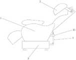
图1为本发明的整体结构示意图;Fig. 1 is the overall structure schematic diagram of the present invention;
图2为本发明的安装盒内部结构剖视图;Fig. 2 is the sectional view of the internal structure of the installation box of the present invention;
图3为本发明的安装盒底部仰视图;Fig. 3 is the bottom view of the bottom of the installation box of the present invention;
图4为本发明的手动推拉装置结构示意图;4 is a schematic structural diagram of a manual push-pull device of the present invention;
图5为本发明的无线控制器外部结构示意图;5 is a schematic diagram of the external structure of the wireless controller of the present invention;
图6为本发明的工作流程图。FIG. 6 is a working flow chart of the present invention.
附图说明:1、座椅;2、VR模拟机;3、移动模块;31、安装盒;32、支撑块;32a、脚垫;33、移动电源;33a、固定板;34、支撑架;34a、U型夹座一;34b、U型夹座二;35、驱动装置;35a、人字架一;35b、驱动轮;35c、轴套;35d、驱动电机;36、转向装置;36a、人字架二;36b、转向轮;37、电动推杆一;38、电动推杆二;39、牵引座;4、手动推拉装置;41、伸缩杆;42、挡块;43、握把;44、无线控制器;44a、外壳;44a-1、单孔耳朵;44b、显示面板;44c、按钮开关模组。Description of drawings: 1. seat; 2. VR simulator; 3. mobile module; 31. installation box; 32, support block; 32a, foot pad; 33, mobile power supply; 33a, fixed plate; 34, support frame; 34a, U-shaped clamp seat one; 34b, U-shaped clamp seat two; 35, drive device; 35a, herringbone frame one; 35b, drive wheel; 35c, axle sleeve; 35d, drive motor; 36, steering device; 36a, Herringbone frame two; 36b, steering wheel; 37, electric push rod one; 38, electric push rod two; 39, traction seat; 4, manual push-pull device; 41, telescopic rod; 42, block; 43, grip; 44. Wireless controller; 44a, shell; 44a-1, single-hole ear; 44b, display panel; 44c, button switch module.
具体实施方式Detailed ways
为了便于理解本发明,下面将参照相关附图对本发明进行更加全面的描述,附图中给出了本发明的若干实施例,但是本发明可以通过不同的形式来实现,并不限于文本所描述的实施例,相反的,提供这些实施例是为了使对本发明公开的内容更加透彻全面。In order to facilitate the understanding of the present invention, the present invention will be described more fully hereinafter with reference to the related drawings. Several embodiments of the present invention are given in the drawings, but the present invention can be implemented in different forms and is not limited to the description in the text. rather, these embodiments are provided so that this disclosure will be thorough and complete.
需要说明的是,当元件被称为“固设于”另一个元件,它可以直接在另一个元件上也可以存在居中的元件,当一个元件被认为是“连接”另一个元件,它可以是直接连接到另一个元件或者可能同时存在居中元件,本文所使用的术语“垂直的”、“水平的”、“左”、“右”以及类似的表述只是为了说明的目的。It should be noted that when an element is referred to as being "fixed" to another element, it may be directly on the other element or intervening elements may be present, and when an element is referred to as being "connected" to another element, it may be The terms "vertical," "horizontal," "left," "right," and similar expressions used herein are for the purpose of illustration only.
除非另有定义,本文所使用的所有的技术和科学术语与属于本发明的技术领域的技术人员通常连接的含义相同,本文中在本发明的说明书中所使用的术语知识为了描述具体的实施例的目的,不是旨在于限制本发明,本文所使用的术语“及/或”包括一个或多个相关的所列项目的任意的和所有的组合。Unless otherwise defined, all technical and scientific terms used herein have the same meaning as commonly associated by one of ordinary skill in the technical field of the present invention, and the terminology used herein in the description of the present invention is used for the purpose of describing specific embodiments. For the purpose of, and not intended to limit, the present invention, as used herein, the term "and/or" includes any and all combinations of one or more of the associated listed items.
请参照附图1-6所示,一种便于搬运的VR按摩椅,包括座椅1、VR模拟机2和移动模块3,所述座椅1包括靠背部件,所述VR模拟机2位于靠背部件顶端并通过支架与靠背部件两侧呈转动连接,VR模拟机2内置VR眼镜,在使用者躺下后可整体覆盖在脸部,保持VR眼镜和使用者的双眼配合,从而进行VR虚拟情景的代入,所述移动模块3设置于座椅1底部,所述移动模块3包括有安装盒31,所述安装盒31底部开口,所述安装盒31内部中间段设有移动电源33,移动电源33为直流24V电源,所述移动电源33底部设有固定板33a,所述固定板33a底部设有支撑架34,所述支撑架34远离椅背一端设有驱动装置35,所述驱动装置35包括有驱动电机35d(型号2543RCG),所述支撑架34另一端设有转向装置36,所述驱动装置35和转向装置36上端分别设有电动推杆一37(型号IP800)和电动推杆二38(型号IP800),且所述移动电源33分别通过导线与驱动电机35d、电动推杆一37和电动推杆二38呈电性连接,移动电源33上设有无线信号接收器(型号H3V4F),所述驱动电机35d、电动推杆一37和电动推杆二38依次对应无线信号接收器中包含的接收单元一、接收单元二和接收单元三,所述安装盒31靠近转向装置36一端外壁上设有牵引座39,所述牵引座39连接有手动推拉装置4,所述手动推拉装置4包括有无线控制器44,所述无线控制器44内部设有微控制芯片(型号STM32F030C8)和无线信号发射器(型号HW3000),所述无线信号发射器包含指令单元一、指令单元二和指令单元三并依次与所述接收单元一、接收单元二和接收单元三对码连接;Please refer to the accompanying drawings 1-6, a VR massage chair that is easy to carry, includes a
具体的,请参照附图1、4、5和6所示,所述手动推拉装置4包括有伸缩杆41,所述伸缩杆41由套杆和活动杆组成,座椅1背部对应牵引座39的正上方设有固定夹11,收起伸缩杆41后可将套杆上端部位嵌入固定夹11内实施收纳固定,所述套杆远离活动杆一端与牵引座39呈转动连接,所述活动杆端部焊接有挡块42,所述挡块42远离活动杆一侧设有握把43,使用推拉功能时搬运人员将伸缩杆41退出固定夹11并进行拉伸,可利用握把43进行操作,借助牵引座39来拉动座椅1进行移动,所述无线控制器44包括有外壳44a,所述外壳44a两侧对称设有两个单孔耳朵44a-1,两个所述单孔耳朵44a-1均通过螺钉与挡块42靠近握把43一侧固定连接,且所述外壳44a正面设有显示面板44b和按钮开关模组44c,所述显示面板44b和按钮开关模组44c分别通过导线与微控制芯片呈电性连接,通过手动操作按钮开关模组44c来控制微控制芯片进行指令传输,借助无线信号发射器中的指令单元一、指令单元二和指令单元三来依次向移动电源33上的无线信号接收器传达指令信号,从而控制驱动电机35d、电动推杆一37和电动推杆二38所对应的接收单元一、接收单元二和接收单元三接收到指令后实施工作,实现VR按摩椅的前进和后退功能以及驱动装置35和转向装置36的升降功能,显示面板44b便于搬运人员观察当前的指令状态,无线控制器44中将设置微型电池来提供电子元件的正常工作。Specifically, please refer to FIGS. 1 , 4 , 5 and 6 , the manual push-
请参照附图3所示,所述安装盒31底部四个顶角处逐一设有支撑块32,每个所述支撑块32下端均设有脚垫32a,所述脚垫32a通过螺纹杆插入对应的支撑块32内呈螺纹连接,在VR按摩椅到达指定位置后,收起驱动装置35和转向装置36使得座椅1下降,利用四个脚垫32a和地面接触,提高VR按摩椅的稳定性,同时每个脚垫32a均可进行旋转调节高度。Please refer to FIG. 3 , the four top corners of the bottom of the
请参照附图2和3所示,所述固定板33a四个顶角处逐一通过螺栓与支撑架34相固定,所述支撑架34两端分别与安装盒31两侧内壁焊接固定,且所述支撑架34两侧中心处对称焊接有U型夹座一34a和U型夹座二34b,所述驱动装置35还包括有人字架一35a,所述人字架一35a闭口端与U型夹座一34a呈转动连接,所述人字架一35a靠近中心处的顶部与电动推杆一37的输出轴呈转动连接,所述电动推杆一37另一端与安装盒31内顶壁呈转动连接,所述人字架一35a开口端之间横向穿插有轴套35c,所述轴套35c内部活动设有中心轴,该中心轴两端对称设有两个驱动轮35b,且所述驱动电机35d固定于轴套35c中心处并通过齿轮传动结构驱动中心轴旋转,所述驱动电机35d为双头电机,两个驱动轮35b在电动推杆一37推动人字架一35a向下转动后和地面接触,便于座椅1的移动,同时驱动电机35d方面利用双头电机的特点,能够同步带动两个驱动轮35b进行旋转。Please refer to FIGS. 2 and 3 , the four top corners of the fixing
请参照附图2和3所示,所述转向装置36包括有人字架二36a,所述人字架二36a闭口端与U型夹座二34b呈转动连接,所述人字架二36a靠近中心处的顶部与电动推杆二38输出轴呈转动连接,所述电动推杆二38另一端与安装盒31内顶壁呈转动连接,所述人字架二36a开口端对称设有两个转向轮36b,每个所述转向轮36b均与人字架二36a呈转动连接,两个转向轮36b在电动推杆二38推动人字架二36a向下转动后和地面接触,配合两个驱动轮35b一起将座椅1抬升,在座椅1移动时能够进行快速的转向。Referring to FIGS. 2 and 3 , the
本发明的具体流程如下:The concrete flow process of the present invention is as follows:
首先,通过搬运人员将伸缩杆41退出固定夹11并进行拉伸,利用握把43进行操作,使用无线控制器44的按钮开关模组44c来控制微控制芯片进行指令传输,借助无线信号发射器中的指令单元一、指令单元二和指令单元三来依次向移动电源33上的无线信号接收器传达指令信号,从而控制驱动电机35d、电动推杆一37和电动推杆二38所对应的接收单元一、接收单元二和接收单元三接收到指令后实施工作,提供工作电源,先控制电动推杆一37和电动推杆二38同步伸展,使得两个驱动轮35b在电动推杆一37推动人字架一35a向下转动后和地面接触,两个转向轮36b在电动推杆二38推动人字架二36a向下转动后和地面接触,配合两个驱动轮35b一起将座椅1抬升,再控制驱动电机35d工作带动驱动轮35b往指定的方向旋转,从而辅助搬运人员进行座椅1的移动。First, the
上述结合附图对本发明进行了示例性描述,显然本发明具体实现并不受上述方式的限制,只要采用了本发明的方法构思和技术方案进行的这种非实质改进,或未经改进将本发明的构思和技术方案直接应用于其他场合的,均在本发明的保护范围之内。The present invention has been exemplarily described above in conjunction with the accompanying drawings. Obviously, the specific implementation of the present invention is not limited by the above manner, as long as the non-substantial improvement of the method concept and technical solution of the present invention is adopted, or the present invention is modified without improvement. If the concept and technical solutions of the invention are directly applied to other occasions, they all fall within the protection scope of the present invention.
Claims (6)
Priority Applications (1)
| Application Number | Priority Date | Filing Date | Title |
|---|---|---|---|
| CN202010861418.7ACN112043544B (en) | 2020-08-24 | 2020-08-24 | VR massage armchair convenient to transport |
Applications Claiming Priority (1)
| Application Number | Priority Date | Filing Date | Title |
|---|---|---|---|
| CN202010861418.7ACN112043544B (en) | 2020-08-24 | 2020-08-24 | VR massage armchair convenient to transport |
Publications (2)
| Publication Number | Publication Date |
|---|---|
| CN112043544A CN112043544A (en) | 2020-12-08 |
| CN112043544Btrue CN112043544B (en) | 2022-09-02 |
Family
ID=73600465
Family Applications (1)
| Application Number | Title | Priority Date | Filing Date |
|---|---|---|---|
| CN202010861418.7AExpired - Fee RelatedCN112043544B (en) | 2020-08-24 | 2020-08-24 | VR massage armchair convenient to transport |
Country Status (1)
| Country | Link |
|---|---|
| CN (1) | CN112043544B (en) |
Citations (8)
| Publication number | Priority date | Publication date | Assignee | Title |
|---|---|---|---|---|
| JP2001029421A (en)* | 1999-07-23 | 2001-02-06 | Omron Corp | Legless chair-type massager |
| WO2011147087A1 (en)* | 2010-05-26 | 2011-12-01 | Wu Yi | Massage chair with foldable seat |
| CN104684526A (en)* | 2012-07-09 | 2015-06-03 | 谢尔盖·苏列诺维奇·奥西波夫 | Transport devices for transporting goods and people on stairs and flat surfaces |
| CN206491433U (en)* | 2016-12-07 | 2017-09-15 | 重庆银钢科技(集团)有限公司 | Electric trunk |
| CN207306858U (en)* | 2017-03-20 | 2018-05-04 | 潍坊歌尔电子有限公司 | A kind of VR massage armchairs |
| CN208726186U (en)* | 2017-08-16 | 2019-04-12 | 运时通(中国)家具有限公司 | A music massage chair |
| CN109806076A (en)* | 2019-02-27 | 2019-05-28 | 上海电子工业学校 | A kind of protective rescue type commuter chair and protective rescue commuter system |
| CN210493346U (en)* | 2019-07-27 | 2020-05-12 | 深圳市联创科技集团有限公司 | Massage chair convenient to move |
- 2020
- 2020-08-24CNCN202010861418.7Apatent/CN112043544B/ennot_activeExpired - Fee Related
Patent Citations (8)
| Publication number | Priority date | Publication date | Assignee | Title |
|---|---|---|---|---|
| JP2001029421A (en)* | 1999-07-23 | 2001-02-06 | Omron Corp | Legless chair-type massager |
| WO2011147087A1 (en)* | 2010-05-26 | 2011-12-01 | Wu Yi | Massage chair with foldable seat |
| CN104684526A (en)* | 2012-07-09 | 2015-06-03 | 谢尔盖·苏列诺维奇·奥西波夫 | Transport devices for transporting goods and people on stairs and flat surfaces |
| CN206491433U (en)* | 2016-12-07 | 2017-09-15 | 重庆银钢科技(集团)有限公司 | Electric trunk |
| CN207306858U (en)* | 2017-03-20 | 2018-05-04 | 潍坊歌尔电子有限公司 | A kind of VR massage armchairs |
| CN208726186U (en)* | 2017-08-16 | 2019-04-12 | 运时通(中国)家具有限公司 | A music massage chair |
| CN109806076A (en)* | 2019-02-27 | 2019-05-28 | 上海电子工业学校 | A kind of protective rescue type commuter chair and protective rescue commuter system |
| CN210493346U (en)* | 2019-07-27 | 2020-05-12 | 深圳市联创科技集团有限公司 | Massage chair convenient to move |
Also Published As
| Publication number | Publication date |
|---|---|
| CN112043544A (en) | 2020-12-08 |
Similar Documents
| Publication | Publication Date | Title |
|---|---|---|
| CN107898567B (en) | Electric wheelchair with assistive function of getting in and out of bed and obstacle-crossing function | |
| CN106821637B (en) | Omnidirectional multifunctional wheelchair bed | |
| CN201414896Y (en) | A medical movable electric lift bed | |
| CN204541428U (en) | A kind of acoustic control chair lift | |
| US20150366729A1 (en) | Elevator Chair | |
| CN111588573A (en) | Multi-arm cooperative transfer nursing robot | |
| CN112043544B (en) | VR massage armchair convenient to transport | |
| CN212630367U (en) | Intelligent sofa with electric lifting and folding functions | |
| CN208525265U (en) | A kind of turning over mechanism and its bed capable of nursing and supporting patient of bed capable of nursing and supporting patient | |
| CN210852567U (en) | Automatic lifting chassis type dining car | |
| CN202317898U (en) | Stone polishing device | |
| CN218075490U (en) | An auxiliary electric trolley for the elderly | |
| CN203131364U (en) | Lifting device of computer monitor | |
| CN106510986B (en) | A kind of multifunction nursing electric wheelchair | |
| CN206324933U (en) | An intelligent electric wheelchair capable of automatic charging | |
| CN205649208U (en) | Multi -functional electronic seat base | |
| CN211433729U (en) | Multifunctional push bed | |
| CN102278582A (en) | Adjustable notebook computer bracket | |
| CN101991493B (en) | Integral lifting type domestic nursing bed and front and back bed surface leveling method | |
| CN219937771U (en) | Handcart switching device | |
| CN110742739A (en) | Multifunctional push bed | |
| CN216992988U (en) | Extruder is used in cable production convenient to remove | |
| CN217040539U (en) | Electric wheelchair seat inclination adjusting mechanism | |
| CN218208769U (en) | Lift display screen based on speech control | |
| CN221512513U (en) | Anti-tilting device of electric wheelchair |
Legal Events
| Date | Code | Title | Description |
|---|---|---|---|
| PB01 | Publication | ||
| PB01 | Publication | ||
| SE01 | Entry into force of request for substantive examination | ||
| SE01 | Entry into force of request for substantive examination | ||
| GR01 | Patent grant | ||
| GR01 | Patent grant | ||
| CF01 | Termination of patent right due to non-payment of annual fee | ||
| CF01 | Termination of patent right due to non-payment of annual fee | Granted publication date:20220902 |