CN112041696A - Gradient shielded coils for MRI devices - Google Patents
Gradient shielded coils for MRI devicesDownload PDFInfo
- Publication number
- CN112041696A CN112041696ACN201980029302.2ACN201980029302ACN112041696ACN 112041696 ACN112041696 ACN 112041696ACN 201980029302 ACN201980029302 ACN 201980029302ACN 112041696 ACN112041696 ACN 112041696A
- Authority
- CN
- China
- Prior art keywords
- gradient
- winding
- coil
- meander
- shield coil
- Prior art date
- Legal status (The legal status is an assumption and is not a legal conclusion. Google has not performed a legal analysis and makes no representation as to the accuracy of the status listed.)
- Granted
Links
Images

Classifications
- G—PHYSICS
- G01—MEASURING; TESTING
- G01R—MEASURING ELECTRIC VARIABLES; MEASURING MAGNETIC VARIABLES
- G01R33/00—Arrangements or instruments for measuring magnetic variables
- G01R33/20—Arrangements or instruments for measuring magnetic variables involving magnetic resonance
- G01R33/28—Details of apparatus provided for in groups G01R33/44 - G01R33/64
- G01R33/38—Systems for generation, homogenisation or stabilisation of the main or gradient magnetic field
- G01R33/385—Systems for generation, homogenisation or stabilisation of the main or gradient magnetic field using gradient magnetic field coils
- G—PHYSICS
- G01—MEASURING; TESTING
- G01R—MEASURING ELECTRIC VARIABLES; MEASURING MAGNETIC VARIABLES
- G01R33/00—Arrangements or instruments for measuring magnetic variables
- G01R33/20—Arrangements or instruments for measuring magnetic variables involving magnetic resonance
- G01R33/28—Details of apparatus provided for in groups G01R33/44 - G01R33/64
- G01R33/38—Systems for generation, homogenisation or stabilisation of the main or gradient magnetic field
- G01R33/381—Systems for generation, homogenisation or stabilisation of the main or gradient magnetic field using electromagnets
- G01R33/3815—Systems for generation, homogenisation or stabilisation of the main or gradient magnetic field using electromagnets with superconducting coils, e.g. power supply therefor
- G—PHYSICS
- G01—MEASURING; TESTING
- G01R—MEASURING ELECTRIC VARIABLES; MEASURING MAGNETIC VARIABLES
- G01R33/00—Arrangements or instruments for measuring magnetic variables
- G01R33/20—Arrangements or instruments for measuring magnetic variables involving magnetic resonance
- G01R33/28—Details of apparatus provided for in groups G01R33/44 - G01R33/64
- G01R33/42—Screening
- G01R33/421—Screening of main or gradient magnetic field
- G01R33/4215—Screening of main or gradient magnetic field of the gradient magnetic field, e.g. using passive or active shielding of the gradient magnetic field
Landscapes
- Physics & Mathematics (AREA)
- Condensed Matter Physics & Semiconductors (AREA)
- General Physics & Mathematics (AREA)
- Health & Medical Sciences (AREA)
- Epidemiology (AREA)
- Electromagnetism (AREA)
- Magnetic Resonance Imaging Apparatus (AREA)
Abstract
Translated fromChinese
Description
Translated fromChinese技术领域technical field
本发明涉及MRI成像的领域,并且尤其涉及用于MRI装置的梯度屏蔽线圈。The present invention relates to the field of MRI imaging, and in particular to gradient shielded coils for MRI devices.
背景技术Background technique
作为产生患者体内图像的过程的部分,在磁共振成像(MRI)中使用磁场来使原子的核自旋对齐。该磁场称为主磁场或B0场。在MRI扫描期间,由发射器或放大器和天线生成的射频(RF)脉冲引起对局部磁场的扰动,并可用于操纵核自旋相对于B0场的方向。可以通过使用所谓的梯度线圈来实现磁自旋的空间编码,所述梯度线圈用于将磁场梯度叠加在B0磁场上。核自旋发射的RF信号由接收器线圈探测,并且这些RF信号用于生成MRI图像。Magnetic fields are used in magnetic resonance imaging (MRI) to align the nuclear spins of atoms as part of the process of producing images of a patient's body. This magnetic field is called the main magnetic field or B0 field. During an MRI scan, radio frequency (RF) pulses generated by a transmitter or amplifier and antenna induce perturbations to the local magnetic field and can be used to manipulate the orientation of nuclear spins relative to the B0 field. Spatial encoding of magnetic spins can be achieved by using so-called gradient coils for superimposing magnetic field gradients on the B0 magnetic field. The RF signals emitted by the nuclear spins are detected by receiver coils, and these RF signals are used to generate MRI images.
用于生成B0场的磁体通常使用超导线圈。由梯度线圈生成的磁场能够引起涡流,并因此导致超导线圈内以及超导磁体内部的导电结构内的耗散。这些涡流可以通过使用带有主动屏蔽的梯度线圈来降低。US 2016/0139221 A1公开了一种采取梯度屏蔽线圈形式的主动屏蔽,其围绕MRI装置的梯度线圈。The magnets used to generate the B0 field typically use superconducting coils. The magnetic field generated by the gradient coils can induce eddy currents and thus dissipation within the superconducting coils and within the conductive structures inside the superconducting magnets. These eddy currents can be reduced by using gradient coils with active shielding. US 2016/0139221 A1 discloses an active shield in the form of a gradient shield coil, which surrounds the gradient coil of an MRI apparatus.
根据US 2016/0139221 A1,提供了一种用于磁共振成像系统的磁梯度线圈。磁梯度线圈被主动屏蔽,其中,磁梯度线圈可操作用于生成磁场。磁场具有圆柱对称轴,并且梯度线圈的长度与圆柱对称轴平行。磁梯度线圈具有外表面。磁场包括在外表面外部的外部磁场。该外部磁场沿着长度方向具有至少四个减小的磁场区域,其中,磁场的模量小于沿着长度方向的磁场的模量的平均值。According to US 2016/0139221 A1, a magnetic gradient coil for a magnetic resonance imaging system is provided. The magnetic gradient coils are actively shielded, wherein the magnetic gradient coils are operable to generate a magnetic field. The magnetic field has an axis of cylindrical symmetry, and the length of the gradient coils is parallel to the axis of cylindrical symmetry. The magnetic gradient coil has an outer surface. The magnetic field includes an external magnetic field external to the outer surface. The external magnetic field has at least four regions of decreasing magnetic field along the length, wherein the modulus of the magnetic field is less than the average value of the moduli of the magnetic fields along the length.
此外,从US 2010/0194393 A1已知一种梯度线圈设备,所述梯度线圈设备可以抑制误差磁场的生成并因此抑制涡流,其可以改善截面图像的图像质量。相应的MRI设备包括:第一线圈,其在MRI设备的成像区域处生成线性磁场分布;以及第二线圈,其抑制磁场从第一线圈向静态磁场线圈设备的泄漏,所述静态磁场线圈设备在成像区域处生成均匀磁场分布。Furthermore, from US 2010/0194393 A1 a gradient coil device is known which can suppress the generation of error magnetic fields and thus eddy currents, which can improve the image quality of cross-sectional images. A corresponding MRI apparatus includes: a first coil that generates a linear magnetic field distribution at an imaging region of the MRI apparatus; and a second coil that suppresses leakage of the magnetic field from the first coil to the static magnetic field coil apparatus, the static magnetic field coil apparatus being A uniform magnetic field distribution is generated at the imaging area.
该美国专利申请被设计为针对屏蔽的梯度线圈实现适当的屏蔽功能,其中,屏蔽线圈和屏蔽线圈之间的间隙随圆周方向变化。该屏蔽梯度线圈在场线圈与屏蔽线圈之间的间隙附近的狭窄区域的径向相对位置处具有带有两个周向蛇形的布线图案。This US patent application is designed to achieve a suitable shielding function for shielded gradient coils, wherein the shielding coil and the gap between the shielding coils vary with the circumferential direction. The shield gradient coil has a wiring pattern with two circumferential serpentines at radially opposite positions in a narrow region near the gap between the field coil and the shield coil.
发明内容SUMMARY OF THE INVENTION
本发明的目的是进一步减少MRI系统的磁体的超导线圈和其他导电结构中的耗散。It is an object of the present invention to further reduce dissipation in superconducting coils and other conductive structures of the magnet of an MRI system.
根据本发明,该目的通过独立权利要求的主题得以解决。在子权利要求中描述了本发明的优选实施例。According to the present invention, this object is solved by the subject-matter of the independent claims. Preferred embodiments of the invention are described in the sub-claims.
因此,根据本发明,提供了一种用于MRI装置的梯度屏蔽线圈,所述梯度屏蔽线圈包括围绕其纵轴的绕组,其中,至少一个绕组通过在其圆周上包括多个邻接的部分而被布置为曲折(meandering)绕组,其中,在这些部分的每一个中,以如下的方式提供了一对导体回路,其使得所述曲折绕组中的电流将在两个导体回路中以相反的方向流动。Accordingly, according to the present invention, there is provided a gradient shield coil for an MRI apparatus, the gradient shield coil comprising windings around its longitudinal axis, wherein at least one winding is surrounded by a plurality of contiguous portions on its circumference Arranged as meandering windings, wherein in each of these sections a pair of conductor loops are provided in such a way that current in the meandering winding will flow in opposite directions in the two conductor loops .
根据本发明,圆柱形磁体部件中的大循环电流被转换成大量的局部涡流,这导致这些部件的耗散较少和机械激励较少。针对z梯度线圈的主动屏蔽层的最佳电流分布通常在线圈的两端和平面中间附近具有较低的电流密度。通过在引线之间具有空的空间的一组分立的匝来近似此理想电流分布导致外部磁场缺陷,从而引起在辐射屏蔽或磁体的内孔衬里等结构中产生大量的循环电流。这些电流导致这些组件的耗散和机械激励。如上所述,通过将这些圆形绕组变换为至少一个曲折绕组,磁体中的感应电流可以被变换为非常局部的循环电流的模式。这些涡流衰减更快,耗散更少并引起更少的机械激励。因此,根据本发明,磁体中的耗散可以以至少为2的因子减少。According to the invention, the large circulating currents in the cylindrical magnet parts are converted into a large number of local eddy currents, which results in less dissipation and less mechanical excitation of these parts. The optimal current distribution for an active shield for a z-gradient coil typically has lower current densities at the ends of the coil and near the middle of the plane. Approximation of this ideal current distribution by a set of discrete turns with empty spaces between the leads results in external magnetic field defects, causing large circulating currents in structures such as radiation shields or bore linings of magnets. These currents cause dissipation and mechanical excitation of these components. By transforming these circular windings into at least one meandering winding, as described above, the induced currents in the magnets can be transformed into very local patterns of circulating currents. These eddy currents decay faster, dissipate less and cause less mechanical excitation. Therefore, according to the present invention, the dissipation in the magnet can be reduced by a factor of at least 2.
通常,两个导体回路可以是闭合的或几乎闭合的回路。但是,当涉及到这些导体回路以及电流在这些导体回路中以相反方向流动的特征时,这还包括以下情况:这些导体回路仅由曲折绕组的一部分形成,它们部分地以不同的方式延伸,优选地是相反的方向,优选地在曲折绕组的圆周的相同长度上,即在曲折绕组的相同部分中。Typically, the two conductor loops can be closed or nearly closed loops. However, when it comes to these conductor loops and the characteristic that the current flows in opposite directions in these conductor loops, this also includes the case where these conductor loops are formed by only a part of the meander windings, which partially extend in different ways, preferably The ground is the opposite direction, preferably over the same length of the circumference of the meander winding, ie in the same part of the meander winding.
通常,导体回路可以以不同的方式布置在所述部分内。然而,根据本发明的优选实施例,在每个部分中,两个导体回路沿着绕组的圆周以相同的长度彼此相邻地布置。In general, the conductor loops can be arranged in the section in different ways. However, according to a preferred embodiment of the invention, in each section, two conductor loops are arranged adjacent to each other with the same length along the circumference of the winding.
通过在每个部分中提供一对导体回路,已经可以实现本发明的正面效果。替代地,根据本发明的优选实施例,在每个部分中以如下的方式提供多对回路:使得曲折绕组中的电流将在相应的对的两个导体回路中以相反的方向流动。在该情况下,优选地,在每个部分中,导体回路沿着绕组的圆周以相同的长度彼此相邻地布置。The positive effects of the present invention have been achieved by providing a pair of conductor loops in each section. Alternatively, according to a preferred embodiment of the invention, multiple pairs of loops are provided in each section in such a way that the current in the meander winding will flow in opposite directions in the two conductor loops of the respective pair. In this case, preferably, in each section, the conductor loops are arranged adjacent to each other with the same length along the circumference of the winding.
为了实现本发明的正面效果,可以使用沿着曲折绕组的圆周的截面的不同布置。然而,根据本发明的优选实施例,具有成对的导体回路的部分沿着曲折绕组的圆周彼此以规则的间隔布置。In order to achieve the positive effects of the present invention, different arrangements of sections along the circumference of the meander winding can be used. However, according to a preferred embodiment of the present invention, the sections with pairs of conductor loops are arranged at regular intervals from each other along the circumference of the meander winding.
此外,优选的是,梯度线圈为具有两个开口端的圆柱形状,并且至少一个曲折绕组布置在这些开口端中的一个处。还优选的是,在这些开口端的两个端分别布置至少一个曲折绕组。进一步优选地,在线圈的平面中间附近布置至少一个曲折绕组。优选地,在开口端的区域和平面中间的区域中的绕组密度较小。此外,根据本发明的优选实施例,在其中间区域布置至少两个曲折绕组。Furthermore, it is preferable that the gradient coil has a cylindrical shape with two open ends, and that at least one meander winding is arranged at one of these open ends. It is also preferred that at least one meander winding is arranged at both ends of these open ends, respectively. Further preferably, at least one meander winding is arranged near the middle of the plane of the coil. Preferably, the winding density is less in the region of the open end and in the region mid-plane. Furthermore, according to a preferred embodiment of the present invention, at least two meander windings are arranged in the middle region thereof.
优选地,在曲折绕组附近设置至少一个弯曲(curved)绕组,其中,弯曲绕组不笔直地延伸,但也不像曲折绕组包括任何导体回路。优选地,在每个曲折绕组附近布置有弯曲绕组。Preferably, at least one curved winding is provided adjacent to the meander winding, wherein the curved winding does not extend straight, but also does not include any conductor loops like the meander winding. Preferably, a meander winding is arranged adjacent to each meander winding.
根据本发明的优选实施例,使用诸如冲压或喷水切割的方法用铜板制造曲折绕组。替代地,根据本发明的优选实施例,曲折绕组从中空导体缠绕。According to a preferred embodiment of the present invention, the meander windings are fabricated from copper sheets using methods such as stamping or water jet cutting. Alternatively, according to a preferred embodiment of the present invention, the meander winding is wound from a hollow conductor.
本发明还涉及一种MRI装置,其包括用于生成MRI装置的主磁场的超导磁体和用于生成叠加主磁场的梯度磁场的至少一个梯度线圈,其中,梯度线圈被超导磁体包围,并且其中,如上所述,通过设置在超导磁体与梯度线圈之间的梯度场线圈将超导磁体与梯度磁场屏蔽。The invention also relates to an MRI apparatus comprising a superconducting magnet for generating a main magnetic field of the MRI apparatus and at least one gradient coil for generating a gradient magnetic field superimposing the main magnetic field, wherein the gradient coil is surrounded by the superconducting magnet, and Here, as described above, the superconducting magnet is shielded from the gradient magnetic field by the gradient field coil provided between the superconducting magnet and the gradient coil.
根据MRI装置的优选实施例,梯度线圈包括在梯度线圈的平面中间附近的鞍形绕组,并且至少一个曲折绕组在比其他区域中绕组密度更低的区域中在梯度线圈的平面中间附近在鞍形绕组之上以如下的方式布置:其使得超导磁体不受这些鞍形绕组的影响。According to a preferred embodiment of the MRI apparatus, the gradient coils comprise saddle windings near the middle of the plane of the gradient coils, and the at least one meander winding is in the saddle near the middle of the plane of the gradient coils in regions with a lower winding density than other regions Above the windings are arranged in such a way that the superconducting magnet is not affected by these saddle windings.
本发明还涉及一种通过在超导磁体与梯度线圈之间布置梯度屏蔽线圈来将超导磁体从由MRI装置的梯度线圈生成的梯度磁场屏蔽的方法,所述梯度屏蔽线圈包括围绕其纵向轴的绕组,其中,至少一个绕组通过在其圆周上包括多个邻接的部分而被布置为曲折绕组,其中,在这些部分的每一个中,提供了一对导体回路,其中,曲折绕组中的电流在两个导体回路中以相反的方向流动。The invention also relates to a method of shielding a superconducting magnet from a gradient magnetic field generated by a gradient coil of an MRI apparatus by arranging a gradient shielding coil between the superconducting magnet and a gradient coil, the gradient shielding coil comprising about its longitudinal axis winding, wherein at least one winding is arranged as a meander winding by including a plurality of contiguous sections on its circumference, wherein in each of these sections a pair of conductor loops is provided, wherein the current in the meander winding is Flow in opposite directions in the two conductor loops.
如上所述的梯度屏蔽线圈的优选实施例也造成MRI装置的优选实施例以及屏蔽超导磁体免受由MRI装置的梯度线圈生成的梯度磁场的影响的方法。The preferred embodiments of the gradient shielding coils described above also result in preferred embodiments of the MRI apparatus and method of shielding the superconducting magnet from the gradient magnetic fields generated by the gradient coils of the MRI apparatus.
附图说明Description of drawings
参考本文下文中所描述的实施例,本发明的这些和其他方面将显而易见并将得以阐述。这样的实施例不一定表示本发明的完全范围,然而,并且因此参考权利要求书和本文以解释本发明的范围。These and other aspects of the invention will be apparent from and will be elucidated with reference to the embodiments described hereinafter. Such embodiments do not necessarily represent the full scope of the invention, however, and reference is therefore made to the claims and this document to interpret the scope of the invention.
在附图中:In the attached image:
图1以截面图示意性地描绘了根据本发明的优选实施例的MRI装置,Figure 1 schematically depicts an MRI apparatus according to a preferred embodiment of the present invention in a cross-sectional view,
图2以侧视图示意性地描绘了根据本发明的优选实施例的梯度屏蔽线圈,并且Figure 2 schematically depicts a gradient shield coil according to a preferred embodiment of the present invention in side view, and
图3示意性地描绘了图2的曲折绕组7的部分的放大图。FIG. 3 schematically depicts an enlarged view of a portion of the meander winding 7 of FIG. 2 .
附图标记列表:List of reference numbers:
MRI装置 1MRI unit 1
磁体 2
射频线圈 3RF coil 3
梯度线圈 4Gradient Coils 4
梯度屏蔽线圈 5
常规绕组 6Conventional winding 6
曲折绕组 7meander winding 7
部分 8
导体回路 9
导体回路 10
患者台 11Patient table 11
患者 12patient 12
弯曲绕组 13Bend winding 13
膛 14bore 14
梯度屏蔽线圈的纵轴 ALongitudinal axis A of the gradient shield coil
具体实施方式Detailed ways
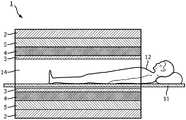
图1以截面图示意性地描绘了根据本发明的优选实施例的MRI装置1。该MRI装置1包括用于生成MRI装置1的主磁场(B0场)的超导磁体2。该超导磁体2包括超导线圈,因为对于MRI成像通常需要几个特斯拉的磁场。为了成像,该磁场用于使检查对象内的原子的核自旋对齐,所述检查对象通常是位于MRI装置1的膛14内的患者台11上的患者12。在MRI扫描期间,RF线圈3用于生成射频(RF)脉冲,以引起对局部磁场的扰动。以此方式,可以控制核自旋相对于B0场的取向。为了对磁自旋进行空间编码,提供了梯度线圈4,即x、y和z梯度线圈4,它们将磁场梯度叠加在由超导磁体2生成的B0磁场上。Figure 1 schematically depicts an MRI apparatus 1 according to a preferred embodiment of the present invention in a cross-sectional view. The MRI apparatus 1 includes a
由梯度线圈4生成的外部磁场可能引起涡流,并且因此在超导磁体2的超导线圈内耗散。可以通过使用梯度屏蔽线圈5(即,x、y和z梯度屏蔽线圈5)来减小这些涡流,所述梯度屏蔽线圈5围绕梯度线圈4,并且因此,将屏蔽超导磁体2的超导线圈屏蔽于由梯度线圈4生成的梯度场。梯度线圈4和梯度屏蔽线圈5都可以被冷却,例如通过使水流过空心导体(未示出)来冷却。The external magnetic field generated by the gradient coils 4 may induce eddy currents and thus dissipate within the superconducting coils of the
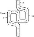
图2以侧视图更详细地示意性地描绘了根据本发明的优选实施例的z梯度屏蔽线圈5。如从图2可以看出,梯度屏蔽线圈5具有有两个开放端的圆柱形状,并且包括直绕组6,弯曲绕组7和绕其纵轴A曲折绕组13。z梯度线圈5相对于中间的z=0平面具有反对称性。Figure 2 schematically depicts a z-
在z梯度屏蔽线圈5的左端和右端以及在z=0附近的区域中的z梯度屏蔽线圈的中间,绕组密度较小。在这些区域中,布置了曲折绕组7。在曲折绕组7附近提供有弯曲绕组13,它们不像直线绕组6那样直线延伸,而是具有波浪形设计。在弯曲绕组13之间布置有规则的、直线的绕组6。在z梯度屏蔽线圈5的端部和中间的区域中,直绕组6彼此的间隔小于弯曲绕组13和曲折绕组7与相邻绕组的间隔。要注意的是,图2是示意图,其中为了清楚起见和易于理解,仅示出了减少数量的绕组6、7、13。The winding density is smaller at the left and right ends of the z-
曲折绕组7沿其圆周包括多个邻接的部分8、8'、8”、8”',其中,在这些部分8、8'、8”、8”'的每一个中,以如下的方式设置了一对导体回路9,10:使得弯曲绕组7中的电流在两个导体回路9、10中以相反的方向流动。这在图3中更详细地示出,图3是图2中的曲折绕组7的部分的示意性放大图,其中,电流的方向由相继的箭头指示。左侧回路9中的电流方向为逆时针方向,而右侧回路10中的电流方向为顺时针方向。The meander winding 7 comprises along its circumference a plurality of adjoining
以此方式,超导磁体2的圆柱形部分中的大循环电流被转换成多个局部涡流,从而在磁体2中引起更少的耗散和更少的机械激励。通过在梯度屏蔽线圈5的两端以及在线圈的平面中间(z=0)附近的区域中设置曲折绕组7,将超导磁体2中的感应电流转换成仅在局部循环的电流的模式。这些局部涡流衰减更快,耗散更少并且在超导磁体2中引起更少的机械激励。这样,可以将超导磁体2中的耗散以至少为2的因子减小。In this way, large circulating currents in the cylindrical portion of the
根据本发明的优选实施例,曲折绕组7和弯曲绕组13由通过冲压或喷水切割制造的铜板制造。替代地,根据本发明的另一优选实施例,曲折绕组7和弯曲绕组13可以由空心导体缠绕。According to a preferred embodiment of the present invention, the meander winding 7 and the meander winding 13 are manufactured from copper sheets manufactured by stamping or water jet cutting. Alternatively, according to another preferred embodiment of the present invention, the meander winding 7 and the meander winding 13 may be wound by hollow conductors.
如可以从图2和3中得知,在每个部分8中,两个导体回路9、10沿着曲折绕组7的圆周以相同的长度彼此相邻地布置。尽管根据图2和图3中所示的优选实施例,仅示出了一个单对导体回路9、10,但是应当强调的是,本发明还允许以如下的方式在每个部分8中提供多对导体回路9、10:使得曲折绕组7中的电流在一对中的两个导体回路9、10中沿相反的方向延伸。As can be seen from FIGS. 2 and 3 , in each
此外,从图2可以看出,在每个部分中,导体回路9、10沿着曲折绕组7的圆周以相同的长度彼此相邻地布置,其中,具有成对的导体回路9、10的部分8沿着曲折绕组7的圆周彼此等间隔地布置。Furthermore, as can be seen from FIG. 2 , in each section the
尽管已经在附图和前面的描述中详细图示和描述了本发明,但是这样的图示和描述应当被认为是图示性或示范性的,而非限制性的。本发明不限于公开的实施例。本领域技术人员通过研究附图、公开内容以及权利要求书,在实践请求保护的本发明时能够理解并且实现对所公开的实施例的其他变型。在权利要求中,“包括”一词不排除其他元件或步骤,并且词语“一”或“一个”不排除多个。尽管特定措施是在互不相同的从属权利要求中记载的,但是这并不指示不能有利地使用这些措施的组合。权利要求书中的任何附图标记不应被解释为对范围的限制。此外,为了清楚起见,可能没有在附图中的所有元件上都提供附图标记。While the invention has been illustrated and described in detail in the drawings and foregoing description, such illustration and description are to be considered illustrative or exemplary and not restrictive. The invention is not limited to the disclosed embodiments. Other modifications to the disclosed embodiments can be understood and effected by those skilled in the art in practicing the claimed invention, from a study of the drawings, the disclosure, and the claims. In the claims, the word "comprising" does not exclude other elements or steps, and the word "a" or "an" does not exclude a plurality. The mere fact that certain measures are recited in mutually different dependent claims does not indicate that a combination of these measures cannot be used to advantage. Any reference signs in the claims shall not be construed as limiting the scope. Furthermore, for the sake of clarity, reference numerals may not be provided on all elements in the figures.
Claims (13)
Applications Claiming Priority (3)
| Application Number | Priority Date | Filing Date | Title |
|---|---|---|---|
| EP18170033.7AEP3564694A1 (en) | 2018-04-30 | 2018-04-30 | Gradient shield coil with meandering winding for a magnetic resonance imaging apparatus |
| EP18170033.7 | 2018-04-30 | ||
| PCT/EP2019/060715WO2019211183A1 (en) | 2018-04-30 | 2019-04-26 | Gradient shield coil with meandering winding for a magnetic resonance imaging apparatus |
Publications (2)
| Publication Number | Publication Date |
|---|---|
| CN112041696Atrue CN112041696A (en) | 2020-12-04 |
| CN112041696B CN112041696B (en) | 2024-08-13 |
Family
ID=62091734
Family Applications (1)
| Application Number | Title | Priority Date | Filing Date |
|---|---|---|---|
| CN201980029302.2AActiveCN112041696B (en) | 2018-04-30 | 2019-04-26 | Gradient shielding coils for MRI devices |
Country Status (5)
| Country | Link |
|---|---|
| US (1) | US11255935B2 (en) |
| EP (2) | EP3564694A1 (en) |
| JP (1) | JP7265561B2 (en) |
| CN (1) | CN112041696B (en) |
| WO (1) | WO2019211183A1 (en) |
Citations (12)
| Publication number | Priority date | Publication date | Assignee | Title |
|---|---|---|---|---|
| US6456076B1 (en)* | 2001-01-31 | 2002-09-24 | The Trustees Of The University Of Pennsylvania | Z gradient shielding coil for canceling eddy currents |
| DE102007028833A1 (en)* | 2006-06-22 | 2007-12-27 | General Electric Co. | Shield coil device, has superconductive wire with two arches that are arranged such that arches are magnetically coupled with magnetic gradient field for locally shielding superconductive magnetic coil |
| WO2008122899A1 (en)* | 2007-04-04 | 2008-10-16 | Koninklijke Philips Electronics N.V. | Split gradient coil and pet/mri hybrid system using the same |
| JP2009279049A (en)* | 2008-05-20 | 2009-12-03 | Hitachi Medical Corp | Magnetic resonance imaging apparatus |
| US20100244836A1 (en)* | 2009-03-31 | 2010-09-30 | General Electric Company | Interleaved gradient coil for magnetic resonance imaging |
| US20100271026A1 (en)* | 2009-04-27 | 2010-10-28 | Bruce Campbell Amm | Transversely folded gradient coil |
| JP2011072461A (en)* | 2009-09-30 | 2011-04-14 | Hitachi Medical Corp | Magnetic resonance imaging apparatus |
| US20120176137A1 (en)* | 2009-09-30 | 2012-07-12 | Hitachi Medical Corporation | Gradient magnetic field coil and magnetic resonance imaging device |
| JP2013022052A (en)* | 2011-07-15 | 2013-02-04 | Hitachi Medical Corp | Coil device, gradient coil for magnetic resonance imaging apparatus, manufacturing method thereof, and magnetic resonance imaging apparatus |
| US20130221968A1 (en)* | 2010-10-07 | 2013-08-29 | Hideta Habara | Antenna device and magnetic resonance imaging device |
| CN104062613A (en)* | 2014-06-13 | 2014-09-24 | 河海大学 | Active shielding gradient coil and designing method thereof |
| CN104062612A (en)* | 2013-03-20 | 2014-09-24 | 布鲁克碧奥斯平股份公司 | Actively Shielded, Cylindrical Gradient Coil System With Passive Rf Shielding For Nmr Devices |
Family Cites Families (5)
| Publication number | Priority date | Publication date | Assignee | Title |
|---|---|---|---|---|
| US4794338A (en)* | 1987-11-25 | 1988-12-27 | General Electric Company | Balanced self-shielded gradient coils |
| US5592087A (en) | 1995-01-27 | 1997-01-07 | Picker International, Inc. | Low eddy current radio frequency shield for magnetic resonance imaging |
| JP4852091B2 (en) | 2008-12-22 | 2012-01-11 | 株式会社日立メディコ | Gradient magnetic field coil apparatus, nuclear magnetic resonance imaging apparatus, and coil pattern design method |
| JP5204813B2 (en)* | 2010-08-06 | 2013-06-05 | 株式会社日立メディコ | Gradient magnetic field coil and magnetic resonance imaging apparatus |
| RU2655474C2 (en) | 2013-06-17 | 2018-05-28 | Конинклейке Филипс Н.В. | Magnetic resonance imaging gradient coil |
- 2018
- 2018-04-30EPEP18170033.7Apatent/EP3564694A1/ennot_activeWithdrawn
- 2019
- 2019-04-26WOPCT/EP2019/060715patent/WO2019211183A1/ennot_activeCeased
- 2019-04-26CNCN201980029302.2Apatent/CN112041696B/enactiveActive
- 2019-04-26USUS17/051,206patent/US11255935B2/enactiveActive
- 2019-04-26JPJP2020558568Apatent/JP7265561B2/enactiveActive
- 2019-04-26EPEP19719312.1Apatent/EP3788391A1/ennot_activeWithdrawn
Patent Citations (13)
| Publication number | Priority date | Publication date | Assignee | Title |
|---|---|---|---|---|
| US6456076B1 (en)* | 2001-01-31 | 2002-09-24 | The Trustees Of The University Of Pennsylvania | Z gradient shielding coil for canceling eddy currents |
| DE102007028833A1 (en)* | 2006-06-22 | 2007-12-27 | General Electric Co. | Shield coil device, has superconductive wire with two arches that are arranged such that arches are magnetically coupled with magnetic gradient field for locally shielding superconductive magnetic coil |
| WO2008122899A1 (en)* | 2007-04-04 | 2008-10-16 | Koninklijke Philips Electronics N.V. | Split gradient coil and pet/mri hybrid system using the same |
| JP2009279049A (en)* | 2008-05-20 | 2009-12-03 | Hitachi Medical Corp | Magnetic resonance imaging apparatus |
| US20100244836A1 (en)* | 2009-03-31 | 2010-09-30 | General Electric Company | Interleaved gradient coil for magnetic resonance imaging |
| US20100271026A1 (en)* | 2009-04-27 | 2010-10-28 | Bruce Campbell Amm | Transversely folded gradient coil |
| JP2011072461A (en)* | 2009-09-30 | 2011-04-14 | Hitachi Medical Corp | Magnetic resonance imaging apparatus |
| US20120176137A1 (en)* | 2009-09-30 | 2012-07-12 | Hitachi Medical Corporation | Gradient magnetic field coil and magnetic resonance imaging device |
| US20130221968A1 (en)* | 2010-10-07 | 2013-08-29 | Hideta Habara | Antenna device and magnetic resonance imaging device |
| JP2013022052A (en)* | 2011-07-15 | 2013-02-04 | Hitachi Medical Corp | Coil device, gradient coil for magnetic resonance imaging apparatus, manufacturing method thereof, and magnetic resonance imaging apparatus |
| CN104062612A (en)* | 2013-03-20 | 2014-09-24 | 布鲁克碧奥斯平股份公司 | Actively Shielded, Cylindrical Gradient Coil System With Passive Rf Shielding For Nmr Devices |
| US20140285201A1 (en)* | 2013-03-20 | 2014-09-25 | Bruker Biospin Ag | Actively shielded, cylindrical gradient coil system with passive RF shielding for NMR devices |
| CN104062613A (en)* | 2014-06-13 | 2014-09-24 | 河海大学 | Active shielding gradient coil and designing method thereof |
Non-Patent Citations (1)
| Title |
|---|
| 侯淑莲;谢寰彤;侯晓吻;李石玉;陈伟;: "永磁微型磁共振成像仪的梯度线圈与图像质量", 波谱学杂志, no. 04* |
Also Published As
| Publication number | Publication date |
|---|---|
| JP2021521948A (en) | 2021-08-30 |
| EP3788391A1 (en) | 2021-03-10 |
| US11255935B2 (en) | 2022-02-22 |
| CN112041696B (en) | 2024-08-13 |
| US20210132168A1 (en) | 2021-05-06 |
| EP3564694A1 (en) | 2019-11-06 |
| JP7265561B2 (en) | 2023-04-26 |
| WO2019211183A1 (en) | 2019-11-07 |
Similar Documents
| Publication | Publication Date | Title |
|---|---|---|
| JP3499973B2 (en) | Transversal gradient coil device with active shield for nuclear spin tomography | |
| EP0231879B1 (en) | Self-shielded gradient coils for nuclear magnetic resonance imaging | |
| JP5497785B2 (en) | Gradient magnetic field coil and nuclear magnetic resonance imaging apparatus | |
| JP7620068B2 (en) | Normal Conducting Electromagnet System | |
| WO2007119726A1 (en) | Magnetic resonance imaging device and gradient magnetic field coil | |
| US6078177A (en) | Flared gradient coil set with a finite shield current | |
| US6342787B1 (en) | Real-time multi-axis gradient distortion correction using an interactive shim set | |
| US11959985B2 (en) | Static-magnetic-field shimming coil system for magnetic resonance imaging | |
| US6278276B1 (en) | Phased array gradient coil set with an off center gradient field sweet spot | |
| JP2005152632A (en) | Mri system utilizing supplemental static field-shaping coils | |
| US6100692A (en) | Gradient coil set with a finite shield current | |
| EP1094330B1 (en) | Apparatus for magnetic resonance imaging and method of designing a gradient coil assembly | |
| CN100571619C (en) | Bull shielded gradient coil with fringing field of improvement | |
| US20240219494A1 (en) | Magnetic resonance imaging systems and components thereof | |
| CN112041696B (en) | Gradient shielding coils for MRI devices | |
| RU2782979C2 (en) | Shielding coil of gradient magnetic field with meander winding for magnetic resonance imaging device | |
| JP7212578B2 (en) | Magnetic resonance imaging device and superconducting magnet | |
| US20190339346A1 (en) | Magnetic Coil With Incomplete Geometric Configuration | |
| US10466320B2 (en) | Multi-layered radio frequency coil | |
| JP5901561B2 (en) | Magnetic resonance imaging system | |
| US20030085789A1 (en) | Gradient coil for a magnetic resonance tomography apparatus, and method for producing same | |
| JP2019033796A (en) | Magnetic resonance imaging system | |
| JP2019118781A (en) | Magnetic resonance imaging device | |
| JP2010046495A (en) | Method of designing gradient magnetic field coil for mri |
Legal Events
| Date | Code | Title | Description |
|---|---|---|---|
| PB01 | Publication | ||
| PB01 | Publication | ||
| SE01 | Entry into force of request for substantive examination | ||
| SE01 | Entry into force of request for substantive examination | ||
| GR01 | Patent grant | ||
| GR01 | Patent grant |