CN112040892A - uterine splint - Google Patents
uterine splintDownload PDFInfo
- Publication number
- CN112040892A CN112040892ACN201980016409.3ACN201980016409ACN112040892ACN 112040892 ACN112040892 ACN 112040892ACN 201980016409 ACN201980016409 ACN 201980016409ACN 112040892 ACN112040892 ACN 112040892A
- Authority
- CN
- China
- Prior art keywords
- uterine
- main body
- guide
- stile
- sliding
- Prior art date
- Legal status (The legal status is an assumption and is not a legal conclusion. Google has not performed a legal analysis and makes no representation as to the accuracy of the status listed.)
- Pending
Links
Images


Classifications
- A—HUMAN NECESSITIES
- A61—MEDICAL OR VETERINARY SCIENCE; HYGIENE
- A61B—DIAGNOSIS; SURGERY; IDENTIFICATION
- A61B17/00—Surgical instruments, devices or methods
- A61B17/42—Gynaecological or obstetrical instruments or methods
- A61B17/4241—Instruments for manoeuvring or retracting the uterus, e.g. during laparoscopic surgery
- A—HUMAN NECESSITIES
- A61—MEDICAL OR VETERINARY SCIENCE; HYGIENE
- A61B—DIAGNOSIS; SURGERY; IDENTIFICATION
- A61B17/00—Surgical instruments, devices or methods
- A61B17/00234—Surgical instruments, devices or methods for minimally invasive surgery
- A61B2017/00292—Surgical instruments, devices or methods for minimally invasive surgery mounted on or guided by flexible, e.g. catheter-like, means
- A61B2017/003—Steerable
- A61B2017/00305—Constructional details of the flexible means
- A61B2017/00314—Separate linked members
- A—HUMAN NECESSITIES
- A61—MEDICAL OR VETERINARY SCIENCE; HYGIENE
- A61B—DIAGNOSIS; SURGERY; IDENTIFICATION
- A61B17/00—Surgical instruments, devices or methods
- A61B2017/00367—Details of actuation of instruments, e.g. relations between pushing buttons, or the like, and activation of the tool, working tip, or the like
- A—HUMAN NECESSITIES
- A61—MEDICAL OR VETERINARY SCIENCE; HYGIENE
- A61B—DIAGNOSIS; SURGERY; IDENTIFICATION
- A61B17/00—Surgical instruments, devices or methods
- A61B2017/0042—Surgical instruments, devices or methods with special provisions for gripping
- A—HUMAN NECESSITIES
- A61—MEDICAL OR VETERINARY SCIENCE; HYGIENE
- A61B—DIAGNOSIS; SURGERY; IDENTIFICATION
- A61B17/00—Surgical instruments, devices or methods
- A61B2017/00535—Surgical instruments, devices or methods pneumatically or hydraulically operated
- A61B2017/00544—Surgical instruments, devices or methods pneumatically or hydraulically operated pneumatically
- A—HUMAN NECESSITIES
- A61—MEDICAL OR VETERINARY SCIENCE; HYGIENE
- A61B—DIAGNOSIS; SURGERY; IDENTIFICATION
- A61B17/00—Surgical instruments, devices or methods
- A61B2017/00535—Surgical instruments, devices or methods pneumatically or hydraulically operated
- A61B2017/00557—Surgical instruments, devices or methods pneumatically or hydraulically operated inflatable
- A—HUMAN NECESSITIES
- A61—MEDICAL OR VETERINARY SCIENCE; HYGIENE
- A61B—DIAGNOSIS; SURGERY; IDENTIFICATION
- A61B17/00—Surgical instruments, devices or methods
- A61B17/34—Trocars; Puncturing needles
- A61B17/3417—Details of tips or shafts, e.g. grooves, expandable, bendable; Multiple coaxial sliding cannulas, e.g. for dilating
- A61B2017/3419—Sealing means between cannula and body
- A—HUMAN NECESSITIES
- A61—MEDICAL OR VETERINARY SCIENCE; HYGIENE
- A61B—DIAGNOSIS; SURGERY; IDENTIFICATION
- A61B17/00—Surgical instruments, devices or methods
- A61B17/42—Gynaecological or obstetrical instruments or methods
- A61B2017/4216—Operations on uterus, e.g. endometrium
- A61B2017/4225—Cervix uteri
Landscapes
- Health & Medical Sciences (AREA)
- Surgery (AREA)
- Life Sciences & Earth Sciences (AREA)
- Biomedical Technology (AREA)
- Medical Informatics (AREA)
- Reproductive Health (AREA)
- Pregnancy & Childbirth (AREA)
- Engineering & Computer Science (AREA)
- Gynecology & Obstetrics (AREA)
- Heart & Thoracic Surgery (AREA)
- Nuclear Medicine, Radiotherapy & Molecular Imaging (AREA)
- Molecular Biology (AREA)
- Animal Behavior & Ethology (AREA)
- General Health & Medical Sciences (AREA)
- Public Health (AREA)
- Veterinary Medicine (AREA)
- Endoscopes (AREA)
- Surgical Instruments (AREA)
Abstract
Description
Translated fromChinese技术领域technical field
本发明涉及一种子宫梃子,更具体地,涉及一种腹腔镜手术时易于操纵子宫移动的子宫梃子。The present invention relates to a uterine stile, more particularly, to a uterine stile which is easy to manipulate the movement of the uterus during laparoscopic surgery.
背景技术Background technique
子宫切除术(Hysterectomy)是妇科手术中最常见的手术形态。过去实行剖腹的腹式子宫切除术(Abdominal Hysterectomy),而近年来广泛实行腹腔镜子宫切除术(Laparoscopic Hysterectomy)。Hysterectomy is the most common form of gynecological surgery. In the past, abdominal hysterectomy (Abdominal Hysterectomy) was performed, but in recent years, laparoscopic hysterectomy (Laparoscopic Hysterectomy) was widely performed.
与剖腹手术相比,腹腔镜手术拥有诸多优点。即,从技术角度来看,可以从解剖学、病理学层面放大观察器官,手术过程中容易靠近阴道和直肠。另外,腹腔镜手术还具有避免腹腔内部器官暴露在大气中,从而降低肠粘连风险的优点。此外,腹腔镜手术对患者来说具有以下优点,即,因剖腹引起的疼痛感非常小,在美观方面优于剖腹手术,由于疼痛感小而缩短了住院时间,可快速恢复到日常生活,感染率和肠梗阻率极低,且出血少。Laparoscopic surgery has many advantages over laparotomy. That is, from a technical point of view, the organs can be magnified from the anatomical and pathological levels, and the vagina and rectum can be easily accessed during the operation. In addition, laparoscopic surgery has the advantage of avoiding the exposure of the internal organs of the abdominal cavity to the atmosphere, thereby reducing the risk of intestinal adhesions. In addition, laparoscopic surgery has the following advantages for patients, namely, very little pain due to laparotomy, superior to laparotomy in terms of aesthetics, shorter hospital stay due to less pain, quick return to daily life, infection Rates and ileus rates are extremely low, and bleeding is minimal.
近年来,对于宫颈癌也施行了使用腹腔镜的手术。在子宫切除术和子宫肌瘤切除术中,子宫的操纵是子宫手术的基础,而在妇科领域中子宫梃子被用作腹腔镜手术的必要工具。In recent years, surgery using laparoscopy has also been performed for cervical cancer. In hysterectomy and myomectomy, the manipulation of the uterus is the basis of uterine surgery, while in the field of gynecology the stile is used as an essential tool for laparoscopic surgery.
子宫梃子易于操纵子宫,从而能够缩短腹腔镜手术的手术时间,目前所使用的子宫梃子可以前后左右操纵子宫,但无法旋转子宫,因此在提高手术的效用性方面尚有不足之处。The uterine stile is easy to manipulate the uterus, which can shorten the operation time of laparoscopic surgery. The currently used uterine stile can manipulate the uterus forward, backward, left and right, but cannot rotate the uterus, so it is still insufficient in improving the effectiveness of the operation.
发明内容SUMMARY OF THE INVENTION
(一)要解决的技术问题(1) Technical problems to be solved
为解决上述问题,本发明提供一种子宫梃子,腹腔镜手术时易于操纵子宫移动。In order to solve the above problems, the present invention provides a uterine stile, which is easy to manipulate the movement of the uterus during laparoscopic surgery.
本发明要解决的技术问题不限于上述技术问题,本发明所属技术领域的普通技术人员可以从下述记载内容中清楚了解到未提及的其他技术问题。The technical problems to be solved by the present invention are not limited to the above technical problems, and those of ordinary skill in the technical field to which the present invention pertains can clearly understand other technical problems not mentioned from the following descriptions.
(二)技术方案(2) Technical solutions
为解决上述技术问题,本发明的一个实施例提供一种子宫梃子,其插入女性阴道、连接所述阴道的子宫颈部和子宫体部,并在腹腔镜手术时操纵子宫的移动,所述子宫梃子包括:主体部,一端部与手柄结合,并向一个方向延伸形成,以插入所述阴道;安装部,与所述主体部的另一端部结合,并且包括在所述主体部的长度方向上贯通形成的引导槽;支承部,设置在所述安装部上,支承所述子宫颈部;滑动部,插入所述引导槽,一端部与所述主体部结合,并向一个方向延伸形成,以插入所述子宫体部;调节部,同时结合到所述滑动部的一端部和所述主体部,沿上述主体部的长度方向往复移动的同时,使所述滑动部在所述主体部的长度方向上往复移动,并且将所述滑动部固定在所述主体部上,调节所述滑动部对于所述主体部的长度;头部,设置在所述滑动部的另一端部,当所述滑动部插入所述子宫体部且被所述子宫体部的上部加压时,变形为与所述子宫体部的内侧子宫底部的形状相对应的倒三角形,当从所述子宫体部取出所述滑动部时,被所述子宫颈部加压,从而恢复至插入所述子宫体部时的形状;以及气囊部,与所述支承部结合,随着向内侧供应空气而膨胀,同时密封所述阴道的内侧。In order to solve the above technical problems, one embodiment of the present invention provides a uterine splint, which is inserted into a female vagina, connects the cervix and uterine body of the vagina, and manipulates the movement of the uterus during laparoscopic surgery. The stile includes: a main body part, one end of which is combined with the handle and extended in one direction to be inserted into the vagina; a mounting part, which is combined with the other end of the main body part and is included in the length direction of the main body part a guide groove formed through; a support part, arranged on the installation part, to support the uterine cervix; a sliding part, inserted into the guide groove, one end part is combined with the main body part, and extended in one direction to form Inserting the uterine body part; the adjusting part is simultaneously coupled to one end of the sliding part and the main body part, and reciprocates along the longitudinal direction of the main body part, while making the sliding part in the length of the main body part Reciprocating movement in the direction, and the sliding part is fixed on the main body part to adjust the length of the sliding part to the main body part; the head part is arranged on the other end of the sliding part, when the sliding part is When the uterus is inserted into the uterus and is pressurized by the upper part of the uterus, it deforms into an inverted triangle corresponding to the shape of the inner uterine fundus of the uterus, and when the uterus is removed from the uterus When the sliding part is pressed by the cervix, it returns to the shape when the uterine body part is inserted; the inside of the vagina.
本发明的实施例中,所述主体部可包括:第一长杆,构成主体;第一引导件,沿所述第一长杆的长度方向以预定长度形成在所述第一长杆上,并具有四边形截面,在第一引导件的一端部突出形成第一限位件,在另一端部突出形成第二限位件;以及导轨,沿所述第一引导件的长度方向延伸形成在所述第一引导件的两侧面,导轨的一端部与所述第二限位件连接,另一端部与所述第一限位件隔开,以在所述导轨与所述第一限位件之间形成插入槽。In an embodiment of the present invention, the main body portion may include: a first long rod forming a main body; a first guide member formed on the first long rod with a predetermined length along the length direction of the first long rod, and has a quadrilateral cross-section, one end of the first guide member protrudes to form a first limiter, and the other end protrudes to form a second limiter; and a guide rail extends along the length direction of the first guide member to form a On both sides of the first guide piece, one end of the guide rail is connected with the second limit piece, and the other end is separated from the first limit piece, so that the guide rail and the first limit piece can be connected between the guide rail and the first limit piece. An insertion slot is formed therebetween.
本发明的实施例中,所述滑动部可包括:第二长杆,向一个方向延伸形成;第二引导件,连接到所述第二长杆的一端部,向一侧方向以预定长度延伸形成,并具有四边形截面形状;以及固定部,形成在所述第二长杆的另一端部,具有与所述第一引导件的截面相对应的截面,在固定部的一端部突出形成有与所述第一限位件相对应的第三限位件,在另一端部突出形成有第四限位件,并与所述插入槽接连。In an embodiment of the present invention, the sliding part may include: a second long rod extending in one direction; a second guide piece connected to one end of the second long rod and extending to one side with a predetermined length is formed and has a quadrangular cross-sectional shape; and a fixing portion is formed on the other end portion of the second long rod and has a cross-section corresponding to the cross-section of the first guide member, and one end portion of the fixing portion is protruded and formed with a A fourth limiting piece is formed protruding from the other end of the third limiting piece corresponding to the first limiting piece, and is connected to the insertion slot.
本发明的实施例中,所述调节部可包括:滑块,包括:第一狭缝,形成为与所述第一引导件的截面形状相对应的截面形状,所述第一引导件插入第一狭缝;第二狭缝,从所述第一狭缝延伸形成,具有与所述固定部的截面形状相对应的截面形状,所述固定部插入第二狭缝;以及第三狭缝,在所述第一狭缝的内周面两侧形成为具有与所述导轨的截面形状相对应的截面形状,所述导轨插入第三狭缝,其中所述滑块沿所述第一引导件往复移动,同时移动所述滑动部,以及调节柄,插入贯通所述滑块而形成的结合槽以连接所述第二狭缝,向所述固定部加压以固定所述滑动部。In an embodiment of the present invention, the adjustment part may include: a slider including: a first slit formed in a cross-sectional shape corresponding to a cross-sectional shape of the first guide member, the first guide member being inserted into the first slit a slit; a second slit extending from the first slit and having a cross-sectional shape corresponding to the cross-sectional shape of the fixing portion inserted into the second slit; and a third slit, Both sides of the inner peripheral surface of the first slit are formed to have a cross-sectional shape corresponding to the cross-sectional shape of the guide rail, the guide rail is inserted into the third slit, wherein the slider is along the first guide The reciprocating movement moves the sliding part and the adjusting handle at the same time, inserts the coupling groove formed through the sliding block to connect the second slit, and presses the fixing part to fix the sliding part.
本发明的实施例中,所述安装部包括:主体块,在主体块的一面沿轴向形成结合槽,以使所述第一长杆的一端部插入;一对长槽,在所述主体块的外周面沿轴向形成;所述引导槽,在轴向方向上贯通所述主体块而形成,并形成为与所述第二引导件的截面形状相对应的截面,以限制所述滑动部的旋转,同时引导所述滑动部的移动;以及一对凹槽,凹陷形成于所述主体块的外周面。In the embodiment of the present invention, the installation part includes: a main body block, a coupling groove is formed on one side of the main body block along the axial direction, so that one end of the first long rod can be inserted; a pair of long grooves are formed in the main body The outer peripheral surface of the block is formed in the axial direction; the guide groove is formed through the main body block in the axial direction, and is formed in a cross-section corresponding to the cross-sectional shape of the second guide to restrict the sliding The rotation of the sliding part guides the movement of the sliding part; and a pair of grooves are formed in the outer peripheral surface of the main body block.
本发明的实施例中,所述引导槽可形成为从所述安装部向所述手柄方向扩大。In an embodiment of the present invention, the guide groove may be formed to expand from the mounting portion toward the handle.
本发明的实施例中,所述支承部可包括:结合盖部,在内周面形成有与所述长槽对应的长突起,并形成有与所述凹槽对应的结合突起,以与所述主体块结合,在外周面上沿圆周方向形成有安装槽;以及杯状部,与所述结合盖部连接,所述子宫颈部插入杯状部内侧。In an embodiment of the present invention, the support portion may include: a coupling cover portion, a long protrusion corresponding to the long groove is formed on the inner peripheral surface, and a coupling protrusion corresponding to the groove is formed so as to be compatible with the long protrusion. The main body block is combined, and an installation groove is formed on the outer peripheral surface along the circumferential direction; and a cup-shaped part is connected with the combined cover part, and the cervix is inserted into the inner side of the cup-shaped part.
本发明的实施例中,在所述结合盖部中可贯通形成与持钩(Tenaculum)结合的结合孔,所述杯状部的上部形成有沿所述杯状部圆周方向形成相同的高度的阶梯部。In an embodiment of the present invention, a coupling hole for coupling with a hook (tenaculum) may be formed through the coupling cover, and an upper portion of the cup-shaped portion is formed with a same height along the circumferential direction of the cup-shaped portion. step section.
本发明的实施例中,所述杯状部的后部的高度可高于前部的高度,使得上部向前方倾斜形成。In the embodiment of the present invention, the height of the rear part of the cup-shaped part may be higher than that of the front part, so that the upper part is formed inclined forward.
本发明的实施例中,可在所述杯状部的下端部的外周面沿圆周方向突出形成导环。In an embodiment of the present invention, a guide ring may be formed protruding from the outer peripheral surface of the lower end portion of the cup-shaped portion in the circumferential direction.
本发明的实施例中,所述导环与所述梯部可以隔开1.5cm至2.5cm。In the embodiment of the present invention, the guide ring and the ladder portion may be spaced apart from each other by 1.5 cm to 2.5 cm.
本发明的实施例中,所述杯状部可以形成为相同的高度,所述结合盖部的上部向前方倾斜形成,使得所述杯状部向前方倾斜形成。In an embodiment of the present invention, the cup-shaped portion may be formed to have the same height, and the upper portion of the coupling cover portion may be formed inclined forward, so that the cup-shaped portion may be formed inclined forward.
本发明的实施例中,可在所述结合盖部和所述杯状部的连接部贯通形成有连接孔,所述连接孔中设有密封部件,所述密封部件包括:第一凸缘,与所述结合盖部一面紧密贴合;第二凸缘,与所述杯状部的一面紧密贴合,并且中央形成有紧贴槽,所述第二引导件贯通紧贴槽。In the embodiment of the present invention, a connecting hole may be formed through the connecting portion of the coupling cover portion and the cup-shaped portion, and a sealing member is arranged in the connecting hole, and the sealing member includes: a first flange, The second flange is in close contact with one side of the cup-shaped portion, and a close contact groove is formed in the center, and the second guide member penetrates through the close contact groove.
本发明的实施例中,所述气囊部可包括:内圈部,包括与所述安装槽结合的安装环,围绕所述结合盖部并向结合盖部的长度方向延伸;第一膨胀部,与所述内圈部连接,围绕所述内圈部的外周面的一部分而形成,被填充空气后膨胀,同时密封所述阴道的内侧;以及第二膨胀部,与所述内圈部连接,围绕所述内圈部的外周面的其余部分而形成,被填充空气后膨胀,同时与所述第一膨胀部独立地密封所述阴道的内侧。In an embodiment of the present invention, the airbag portion may include: an inner ring portion including a mounting ring combined with the mounting groove, surrounding the combined cover portion and extending in the length direction of the combined cover portion; a first expansion portion, connected with the inner ring portion, formed around a part of the outer peripheral surface of the inner ring portion, and inflated after being filled with air, while sealing the inner side of the vagina; and a second inflation portion connected with the inner ring portion, It is formed around the rest of the outer peripheral surface of the inner ring portion, and is inflated after being filled with air, while sealing the inside of the vagina independently of the first inflation portion.
本发明的实施例中,所述头部可包括:延伸部,在所述第二引导件的一端部以与所述第二引导件形成预定角度的方式延伸形成;第一旋转部,与所述延伸部的一端部铰链结合,向所述第二引导件的虚拟的延长线方向旋转,并且在长度方向上形成有安装槽;以及第二旋转部,其一端部与所述第一旋转部的一端部铰链结合,并形成为与所述安装槽相对应的形状,在第二旋转部的另一端部结合有环部,所述环部围绕所述延伸部的外周面,随着所述第一旋转部和所述第二旋转部的旋转而在所述延伸部的长度方向上往复移动。In an embodiment of the present invention, the head part may include: an extension part extending from one end of the second guide part in a manner to form a predetermined angle with the second guide part; a first rotating part, connected to the second guide part One end of the extension part is hingedly connected, rotates in the direction of the virtual extension line of the second guide, and is formed with a mounting groove in the longitudinal direction; and a second rotating part, one end of which is connected to the first rotating part One end of the second rotating part is hinged and formed into a shape corresponding to the installation groove, and the other end of the second rotating part is combined with a ring part, the ring part surrounds the outer peripheral surface of the extension part, and with the The rotation of the first rotating portion and the second rotating portion reciprocates in the longitudinal direction of the extending portion.
本发明的实施例中,当所述头部通过所述子宫颈部插入所述子宫体部时,所述第二旋转部可插入所述安装槽,所述环部位于延伸部的一端部,所述头部向所述滑动部的长度方向延伸;当所述头部继续插入而所述子宫体部的上部对所述第二旋转部的另一端部加压时,所述第二旋转部和所述第一旋转部可转动,所述环部向所述延伸部的另一端部方向移动,以使所述延伸部、所述第一旋转部和所述第二旋转部与所述子宫体部接触。In an embodiment of the present invention, when the head is inserted into the uterine body part through the cervix, the second rotating part can be inserted into the installation groove, and the ring part is located at one end of the extension part, The head part extends in the longitudinal direction of the sliding part; when the head part continues to be inserted and the upper part of the uterus body presses the other end part of the second rotating part, the second rotating part and the first rotating part is rotatable, and the ring part moves in the direction of the other end of the extending part, so that the extending part, the first rotating part and the second rotating part are connected to the uterus body contact.
本发明的实施例中,从所述子宫体部取出所述头部时,当所述子宫体部对所述第一旋转部的另一端部加压时,所述第二旋转部和所述第一旋转部可旋转,所述第二旋转部插入所述安装槽中,所述环部位于延伸部的一端部,以使所述延伸部、所述第一旋转部和所述第二旋转部向所述滑动部的长度方向延伸。In an embodiment of the present invention, when the head is removed from the uterus, when the uterus presses the other end of the first rotating part, the second rotating part and the The first rotating part is rotatable, the second rotating part is inserted into the mounting groove, and the ring part is located at one end of the extending part, so that the extending part, the first rotating part and the second rotating part are rotated The portion extends in the longitudinal direction of the sliding portion.
本发明的实施例中,所述延伸部的直径可小于所述第二引导件的直径,在所述延伸部的一端部可形成有直径大于所述延伸部的第五限位件,所述环部被所述第二引导件和所述第五限位件卡住而停止移动。In an embodiment of the present invention, the diameter of the extension portion may be smaller than the diameter of the second guide member, and a fifth limiting member having a diameter larger than that of the extension portion may be formed at one end of the extension portion. The ring portion is caught by the second guide member and the fifth limiting member to stop moving.
(三)发明效果(3) Invention effect
根据本发明的实施例,当第二旋转部插入第一旋转部的安装槽且环部位于延伸部的一端部时,头部向滑动部的长度方向延伸形成,从而可形成为几乎伸直的“一”字形,由此,头部可易于插入子宫或易于从子宫中取出。According to an embodiment of the present invention, when the second rotating part is inserted into the installation groove of the first rotating part and the ring part is located at one end of the extending part, the head part is formed to extend in the length direction of the sliding part, so that it can be formed to be almost straight "One" shape, whereby the head can be easily inserted into or removed from the uterus.
此外,根据本发明的实施例,第二旋转部和第一旋转部在子宫内部转动,环部向延伸部的另一端方向移动,由此延伸部、第一旋转部和第二旋转部可以与子宫体部接触。即,头部可变为倒三角形。因此,头部可以被固定为符合子宫内腔,即子宫底部的形状,从而在手术时可以前后左右移动子宫,并旋转子宫。In addition, according to the embodiment of the present invention, the second rotating part and the first rotating part rotate inside the uterus, and the ring part moves toward the other end of the extending part, whereby the extending part, the first rotating part and the second rotating part can be combined with Uterine body contact. That is, the head can be turned into an inverted triangle. Therefore, the head can be fixed to conform to the shape of the uterine cavity, the uterine fundus, so that the uterus can be moved back and forth, left and right, and rotated during the operation.
此外,根据本发明的实施例,构成气囊部的第二膨胀部可以独立于第一膨胀部而操作,因此,即使第一膨胀部与第二膨胀部中任意一个发生破裂,剩余的另一个膨胀部仍可防止气体泄漏。Furthermore, according to the embodiment of the present invention, the second inflation portion constituting the airbag portion can operate independently of the first inflation portion, so even if any one of the first inflation portion and the second inflation portion is ruptured, the remaining other inflation portion is inflated still prevent gas leakage.
本发明的效果不限于上述效果,其包括可由本发明的详细说明或权利要求书中记载的发明构成推导出的所有效果。The effects of the present invention are not limited to the above-described effects, and include all effects derived from the invention configuration described in the detailed description of the present invention or the claims.
附图说明Description of drawings
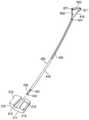
图1是示出根据本发明的一个实施例的子宫梃子的立体图。FIG. 1 is a perspective view illustrating a uterine splint according to an embodiment of the present invention.
图2是示出根据本发明的一个实施例的以子宫梃子的主体部为中心的分解立体图。FIG. 2 is an exploded perspective view showing the center of the body portion of the uterine stile according to one embodiment of the present invention.
图3是示出根据本发明的一个实施例的以子宫梃子的安装部和调节部为中心的立体图。FIG. 3 is a perspective view showing a center of a mounting portion and an adjusting portion of a uterine stile according to an embodiment of the present invention.
图4是示出根据本发明的一个实施例的以子宫梃子的调节部为中心的分解立体图。FIG. 4 is an exploded perspective view showing an adjustment portion of a uterine stile as a center, according to an embodiment of the present invention.
图5是示出根据本发明的一个实施例的以子宫梃子的滑动部为中心的分解立体图。FIG. 5 is an exploded perspective view showing a centering on a sliding portion of a uterine splint according to an embodiment of the present invention.
图6是示出根据本发明的一个实施例的子宫梃子的头部的立体图。6 is a perspective view showing the head of a uterine splint according to one embodiment of the present invention.
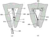
图7是示出根据本发明的一个实施例的子宫梃子的头部的操作例的示意图。FIG. 7 is a schematic diagram showing an example of operation of the head of the uterine splint according to one embodiment of the present invention.
图8是示出根据本发明的一个实施例的子宫梃子的支承部的立体图。8 is a perspective view showing a support portion of a uterine stile according to an embodiment of the present invention.
图9是示出根据本发明的一个实施例的子宫梃子的支承部的剖面立体图。9 is a cross-sectional perspective view showing a support portion of a uterine stile according to an embodiment of the present invention.
图10是示出根据本发明的另一个实施例的子宫梃子的支承部的立体图。10 is a perspective view illustrating a support portion of a uterine stile according to another embodiment of the present invention.
图11是示出根据本发明的又一个实施例的子宫梃子的支承部的立体图。11 is a perspective view illustrating a support portion of a uterine stile according to still another embodiment of the present invention.
图12是图11的A-A’线的剖视图。Fig. 12 is a cross-sectional view taken along the line A-A' in Fig. 11 .
图13是示出根据本发明的一个实施例的以子宫梃子的气囊部为中心的剖面立体图。13 is a perspective view showing a cross-section centering on a balloon portion of a uterine stile according to an embodiment of the present invention.
图14是示出根据本发明的一个实施例的以子宫梃子的第一接合件为中心的剖面示意图。14 is a schematic cross-sectional view showing a center of the first engagement member of the uterine stile according to one embodiment of the present invention.
图15是示出根据本发明的一个实施例的子宫梃子的使用例的示意图。Fig. 15 is a schematic diagram showing an example of use of the uterine splint according to an embodiment of the present invention.
附图标记说明Description of reference numerals
10:阴道 11:子宫颈部10: vagina 11: cervix
12:子宫体部 100:主体部12: Uterine body 100: Main body
120:第一引导件 130:导轨120: First guide 130: Guide rail
200:安装部 300、300a、300b:支承部200: Mounting
310:结合盖部 320:杯状部310: Combination cover part 320: Cup part
321:阶梯部 330:导环321: Step 330: Guide ring
350:密封部件 400:滑动部350: Sealing member 400: Sliding part
420:第二引导件 430:固定部420: Second guide 430: Fixing part
500:调节部 510:滑块500: Adjustment section 510: Slider
520:调节柄 600:头部520: Adjusting handle 600: Head
610:延伸部 620:第一旋转部610: Extension part 620: First rotating part
630:第二旋转部 631:环部630: Second rotating part 631: Ring part
700:气囊部 710:内圈部700: Airbag part 710: Inner ring part
720:第一膨胀部 730:第二膨胀部720: First inflation part 730: Second inflation part
具体实施方式Detailed ways
以下,参照附图对本发明进行说明。本发明可以以多种不同方式实现,因此不限于本说明书中说明的实施例。并且,为了在附图中清楚地说明本发明,省略与说明无关的部分,在整个说明书中,相似的部分使用相似的附图标记。Hereinafter, the present invention will be described with reference to the accompanying drawings. The present invention can be implemented in many different ways and is therefore not limited to the embodiments described in this specification. Also, in order to clearly illustrate the present invention in the drawings, parts irrelevant to the description are omitted, and like reference numerals are used for like parts throughout the specification.
在整个说明书中,当描述某部分与另一部分“连接(联接、接触、结合)”时,不仅包括“直接连接”的情况,还包括中间设有其他构件的“间接连接”的情况。此外,除非另有说明,否则描述某部分“包括”某组件时,表示还可以具备其他组件,而非排除其他组件。Throughout the specification, when a part is described as "connected (coupled, contacted, combined)" with another part, it includes not only the case of "direct connection" but also the case of "indirect connection" with other members interposed therebetween. Furthermore, unless otherwise stated, when a part is described as "comprising" a component, it means that other components may also be present, rather than excluding other components.
本说明书中使用的术语仅用于说明特定实施例,并非限制本发明。除非在文中明确表示不同,否则单数包括复数。需要理解的是,在本说明书中,“包括”或“具有”等术语是用于表示说明书中记载的特征、数字、步骤、动作、组件、部件或其组合的存在,而不是预先排除一个或多个其他特征、数字、步骤、动作、组件、部件或其组合的存在或附加可能性。The terms used in this specification are only used to describe specific embodiments, not to limit the present invention. The singular includes the plural unless the context clearly indicates otherwise. It should be understood that in this specification, terms such as "comprising" or "having" are used to indicate the existence of features, numbers, steps, actions, components, parts or their combinations described in the specification, rather than pre-exclude one or a combination of them. The existence or additional possibility of various other features, numbers, steps, acts, components, parts or combinations thereof.
下面,参照附图对本发明的实施例进行详细说明。Hereinafter, embodiments of the present invention will be described in detail with reference to the accompanying drawings.
图1是示出根据本发明的一个实施例的子宫梃子的立体图。FIG. 1 is a perspective view illustrating a uterine splint according to an embodiment of the present invention.
如图1所示,子宫梃子可以插入女性阴道10(参照图15)、与阴道10连接的子宫颈部11(参照图15)和子宫体部12(参照图15),以在腹腔镜手术时操纵子宫移动。As shown in FIG. 1 , a uterus can be inserted into a female vagina 10 (refer to FIG. 15 ), the cervix 11 (refer to FIG. 15 ) connected to the
子宫梃子可包括主体部100、安装部200、支承部300、滑动部400、调节部500、头部600以及气囊部700。The uterine splint may include a
主体部100可以向一个方向延伸形成而插入阴道10。主体部100的一端部可以结合有手柄140。The
安装部200可以位于主体部100另一端部,支承部300可以设置在安装部200上,并插入阴道10内支承子宫颈部11。The mounting
滑动部400可以贯通安装部200,滑动部的一端部与主体部100结合。滑动部400可以向一个方向延伸形成而插入子宫体部12。The sliding
调节部500可以同时结合到滑动部400的一端部和主体部100。调节部500可以沿主体部100的长度方向进行往复移动的同时,使滑动部400在主体部100的长度方向上进行往复移动,将滑动部400固定在主体部100上,以调节滑动部400对于所述主体部100的长度;The adjusting
头部600可以设置在滑动部400的另一端部。当滑动部400插入子宫体部12并被子宫体部12的上部施压时,头部600发生变形并紧密贴合到子宫体部12内侧的多个位置。此外,当从子宫体部12取出滑动部400时,被子宫颈部11施压,头部发生变形并解除与上述多个位置之间的紧密贴合。The
气囊部700可以与支承部300结合,并随着空气供应到内侧而膨胀,以密封阴道10的内侧。The
图2是示出根据本发明的一个实施例的以子宫梃子的主体部为中心的分解立体图。FIG. 2 is an exploded perspective view showing the center of the body portion of the uterine stile according to one embodiment of the present invention.
如图2所示,主体部可以包括第一长杆110、第一引导件120及导轨130。As shown in FIG. 2 , the main body portion may include a first
第一长杆110可以形成主体部100的主体,并且可以向一个方向延伸形成。The first
第一引导件120可以沿第一长杆110的长度方向以预定长度形成在第一长杆110上。第一引导件120可以具有四边形截面。可以在第一引导件120的一端部突出形成第一限位件121,在另一端部突出形成第二限位件122。The
导轨130可以向第一引导件120的长度方向延伸形成在第一引导件120的两侧面上。The guide rails 130 may be formed on both sides of the
导轨130的一端部可以连接到第二限位件122。并且,导轨130的另一端部可以与第一限位件121隔开形成,以在导轨130另一端部与第一限位件121之间可形成插入槽123。插入槽123可以与第一引导件120接连。One end of the
在主体部100的一端部可以结合有手柄140。手柄140上可形成有连接孔141,主体部100的一端部可以插入连接孔141并与其结合。A
此外,手柄140上可形成有贯通孔142,由此可以减轻手柄140的重量。手柄140可以以主体部100为基准向两侧方向延伸形成,由此,用户在握住手柄140时可以易于传递推动子宫的力和旋转子宫的力。手柄140可由诸如铝的金属或可以进行杀菌消毒的强化树脂构成。In addition, a through
图3是示出根据本发明的一个实施例的以子宫梃子的安装部和调节部为中心的立体图,图4是示出根据本发明的一个实施例的以子宫梃子的调节部为中心的分解立体图,图5是示出根据本发明的一个实施例的以子宫梃子的滑动部为中心的分解立体图。FIG. 3 is a perspective view showing the mounting part and the adjusting part of the stile according to one embodiment of the present invention, and FIG. 4 is an exploded view showing the adjusting part of the uterine stile as the center according to one embodiment of the present invention A perspective view, FIG. 5 is an exploded perspective view showing the sliding portion of the uterine stile as the center according to an embodiment of the present invention.
如图3至图5所示,安装部200可以包括主体块210、长槽211、引导槽212及凹槽213。As shown in FIGS. 3 to 5 , the mounting
主体块210可以形成安装部200的主体,在其一面上形成有与轴向平行的结合槽214。结合槽214中可插入第一长杆110的一端部,由此,安装部200可与主体部100结合。The
长槽211可以在主体块210的外周面沿轴向形成。长槽211可以形成为一对,并以主体块210的中心为基准相互对称。The
引导槽212可以在轴向上贯通主体块210而形成。引导槽212可具有与后述的滑动部400的第二引导件420的截面形状相对应的截面,第二引导件420插入引导槽212。因此,引导槽212可限制滑动部400的旋转并引导滑动部400的移动。The
引导槽212可在安装部200中朝向手柄140方向扩大形成,由此滑动部400通过安装部200后,滑动部400两端以安装部200为基准呈跷跷板形态移动。The
凹槽213凹陷形成在主体块210的外周面。凹槽213可以形成为一对,并以主体块210的中心为基准相互对称。The
滑动部400可以包括第二长杆410、第二引导件420及固定部430。The sliding
第二长杆410可以向一个方向延伸形成。The second
第二引导件420可以连接到第二长杆410的一端部,并以预定长度沿一个方向延伸形成。第二引导件420可以具有四边形截面形状。The
固定部430可以形成在第二长杆410的另一端部。固定部430可以具有与第一引导件120的截面对应的截面。并且,在固定部430一端部可突出形成有第三限位件431,且第三限位件431与第一限位件121相对应。此外,在固定部430的另一端部可突出形成有第四限位件432。The fixing
因此,当固定部430与第一引导件120平行设置时,固定部430可与第一引导件120的外表面接连,也可与插入槽123接连。Therefore, when the fixing
第四限位件432可以呈锥形,以易于插入引导槽212。The fourth limiting
调节部500可以包括滑块510和调节柄520。The
并且,滑块510可以包括第一狭缝511、第二狭缝512及第三狭缝513。Also, the
第一狭缝511形成为具有与第一引导件120的截面形状相对应的截面形状。第一狭缝511形成为向滑块510的一面开放,第一狭缝511中可插入第一引导件120。当第一引导件120插入时,第一引导件120可紧密贴合第一狭缝511。The
第二狭缝512可从第一狭缝511延伸形成,形成为具有与滑动部400的固定部430的截面形状相对应的截面形状。第二狭缝512中可插入固定部430,当固定部430插入时,固定部430紧密贴合第二狭缝512。The
第三狭缝513在第一狭缝511的内周面两侧形成为具有与导轨130的截面形状相对应的截面形状,第三狭缝513中可插入导轨130。当导轨130插入时,导轨130与第三狭缝513紧密贴合。The
滑块510依次插入固定部430和插入槽123并结合,由此,主体部100和滑动部400可与调节部500结合。在上述结合状态下,即,在固定部430与第二狭缝512结合、第一引导件120与第一狭缝511结合、导轨130与第三狭缝513结合的状态下,调节部500可沿第一引导件120进行往复移动。The
当调节部500沿第一引导件120从第一限位件121向第二限位件122方向移动时,第四限位件432被滑块510卡住,滑动部400与调节部500一起移动,由此,滑动部400的冲程缩短。相反,当调节部沿第一引导件12从第二限位件122向第一限位件121方向移动时,第三限位件431被滑块510卡柱,滑动部400与调节部500一起移动,由此,滑动部400的冲程变长。即,调节部500可沿第一引导件120往复移动的同时移动滑动部400,由此调节滑动部400的冲程When the adjusting
滑块510中可贯通形成有连接第二狭缝512的结合槽514。结合槽541的内周面上可形成有第一螺纹515。A
调节柄520可具有加压件521。在加压件521的外周面可形成有第二螺纹522,加压件521可与结合槽514螺纹结合。The adjusting handle 520 may have a
加压件521可与结合槽514结合,并向第二狭缝512的内侧延伸,由此加压件521可对固定部430加压。当加压件521对固定部430加压时,导轨130与第三狭缝513紧密结合并固定滑动部400。The pressing
调节部500可从滑动部400和主体部100中分离,因此,术后可容易进行清洗和消毒。调节部500可由诸如不锈钢的金属或强化树脂形成。The adjusting
图6是示出根据本发明的一个实施例的子宫梃子的头部的立体图,图7是示出根据本发明的一个实施例的子宫梃子的头部的操作例的示意图。6 is a perspective view showing the head of the uterine stile according to one embodiment of the present invention, and FIG. 7 is a schematic diagram showing an operation example of the head of the uterine stile according to one embodiment of the present invention.
如图6及图7所示,头部600可以包括延伸部610、第一旋转部620及第二旋转部630。As shown in FIG. 6 and FIG. 7 , the
延伸部610可以在第二引导件420的一端部以与第二引导件420形成预定角度θ的方式延伸形成。The
延伸部610的直径可小于第二引导件420的直径,在延伸部610的一端部可形成有直径大于延伸部的第五限位件611。The diameter of the
第一旋转部620与延伸部610的一端部铰链结合,由此,第一旋转部620可以以延伸部610的一端部为中心旋转。第一旋转部620可以向第二引导件420的虚拟的延长线L方向旋转。此外,在第一旋转部620中,在第一旋转部620长度方向上可形成安装槽621。The first
第二旋转部630的一端部可以与第一旋转部620的一端部铰链结合,由此,第二旋转部630可以以第一旋转部620的一端部为中心旋转。此外,第二旋转部630的另一端部可以与环部631结合。One end of the second
环部631可以设置为围绕延伸部610的外周面,随着第一旋转部620和第二旋转部630的旋转而在延伸部610长度方向上往复移动。环部631被第二引导件420和第五限位件611卡住而停止移动,由此,可限制第一旋转部620和第二旋转部630的旋转(参照图6的(b))。The
第二旋转部630可形成为与第一旋转部620的安装槽621相对应的形状,因此,当第二旋转部630向第一旋转部620方向旋转时,第二旋转部630可插入第一旋转部620的安装槽621,缩小第一旋转部620和第二旋转部630的宽度,以使延伸部610、第一旋转部620和第二旋转部630向第二引导件420的长度方向延伸(参照图6的(a))。The second
因此,如图7所示,当头部600通过子宫颈部11插入子宫体部12时,第二旋转部630插入安装槽621中,环部631位于延伸部610的一端部,即第五限位件611处,因此头部600可以向滑动部400的长度方向延伸形成。即,头部600可以形成为几乎伸直的“一”字形,从而易于插入。Therefore, as shown in FIG. 7 , when the
并且,当继续插入头部600而子宫体部12的上部A对第二旋转部630的另一端部加压时,第二旋转部630和第一旋转部620旋转,环部631向延伸部610的另一端部方向移动,头部600可变形为与子宫体部的内侧子宫底部形状相对应的倒三角形。由此,第一旋转部620的上端面可与子宫上部接触,头部600的下部与子宫底部紧密贴合。此时,延伸部610、第一旋转部620和第二旋转部630可以与子宫体部12的多个位置B、C相接触。由此,头部600可以被固定和保持符合子宫内腔的形状,手术时可前后左右移动子宫,而且还可以旋转子宫。Then, when the
另一方面,从子宫体部中取出头部600时,子宫体部12对第一旋转部620的另一端部加压,第二旋转部630和第一旋转部620旋转,第二旋转部630插入第一旋转部620的安装槽621,环部631位于延伸部610的第五限位件611处,以使延伸部610、第一旋转部620和第二旋转部630向滑动部400的长度方向延伸。即,头部600可以恢复至插入子宫体部时几乎伸直为“一”字形的形状,从而易于取出。On the other hand, when the
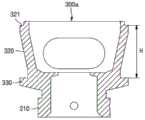
图8是示出根据本发明的一个实施例的子宫梃子的支承部的立体图,图9是示出根据本发明的一个实施例的子宫梃子的支承部的剖面立体图。FIG. 8 is a perspective view showing a support portion of the stile according to an embodiment of the present invention, and FIG. 9 is a cross-sectional perspective view showing the support portion of the stile according to an embodiment of the present invention.
如图8和图9所示,支承部300可以包括结合盖部310和杯状部320。As shown in FIGS. 8 and 9 , the
结合盖部310的内周面可形成有与长槽211对应的长突起311和与凹槽213对应的结合突起312。由此,安装部200可固定结合到结合盖部310的内侧,防止在结合盖部310内侧旋转。The inner peripheral surface of the
结合盖部310的外周面可沿圆周方向形成安装槽313。An outer peripheral surface of the
并且,杯状部320可与结合盖部310连接,子宫颈部11插入其内侧。杯状部320可以形成为椭圆形,且后部比前部高。换而言之,杯状部320的后部的高度高于前部的高度,因此,杯状部320的上部可形成为向前方倾斜。Also, the
杯状部320的两侧可形成有开槽323,通过开槽323可排出手术过程中产生的血液和杂质,而不会积聚在杯状部320中。
在杯状部320的一端部形成有沿杯状部320圆周方向形成相同的高度的阶梯部321。切割阴道10时使用的切割工具随着阶梯部321移动,由此,可移动切割工具而不打滑。At one end of the cup-shaped
此外,在结合盖部310中可贯通形成有结合孔314。结合孔314可以形成为一对,并以结合盖部310的中心为基准相互对称。结合孔314可以与持钩(Tenaculum)结合。当插入阴道10的持钩与结合孔314结合并被拉动时,可易于通过阴道10取出支承部300。支承部300可以由强化树脂形成。In addition, a
并且,在结合盖部310和杯状部320的连接部可贯通形成有连接孔322,并且连接孔322中可具有密封部件350。In addition, a
密封部件350可以包括第一凸缘351及第二凸缘352。The sealing
第一凸缘351紧密贴合于结合盖部310的一面,第二凸缘352紧密贴合于杯状部320的一面。在第二凸缘352的中央可贯通形成有紧贴槽353,第二引导件420可贯通紧贴槽353。紧贴槽353可紧密贴合于第二引导件420。The
密封部件350可由硅构成,以防止手术过程中气体泄漏。The sealing
图10是示出根据本发明的另一个实施例的子宫梃子的支承部的立体图。在本实施例中,支承部中还可设有导环,而其他部分与上述的第一实施例的支承部相同,因此尽量省略重复说明。10 is a perspective view illustrating a support portion of a uterine stile according to another embodiment of the present invention. In this embodiment, a guide ring may also be provided in the support portion, and other parts are the same as the support portion of the above-mentioned first embodiment, so repeated description is omitted as much as possible.
如图10所示,在本实施例中,支承部300a还可包括导环330。导环330可在杯状部320的下端部的外周面沿圆周方向突出形成。导环330可与阶梯部321具有相同的功能。即,切割阴道时使用的切割工具可随着导环330移动,由此,移动切割工具而不打滑。As shown in FIG. 10 , in this embodiment, the
进一步参照图15进行说明,在一般的子宫切除术中,在子宫颈部11的位置上完成阴道10切割。因此,在这种情况下,利用杯状部320的阶梯部321切割阴道10,这样阴道10的切割位置OL1会与阶梯部321的位置相对应。15 , in a typical hysterectomy, incision of the
另一方面,对于宫颈癌,会在子宫颈部11的下方完成阴道10的切割。因此,在这种情况下,会利用导环330进行切割手术。图15中示出了适用图8所示的支承部300的状态,但假设适用本实施例的支承部300a,则阴道10的切割位置OL2会与导环330的位置相对应。On the other hand, for cervical cancer, the incision of the
通常,宫颈癌是在子宫切除术的切割位置下方2cm左右处实施切割。因此,在本实施例中,导环330与阶梯部321间隔开1.5cm至2.5cm的距离H。Usually, cervical cancer is cut about 2cm below the hysterectomy site. Therefore, in the present embodiment, the
图11是示出根据本发明的又一实施例的子宫梃子的支承部的立体图,图11的(a)是从上侧俯视支承部的图,图11的(b)是从下侧仰视支承部的图,图12是图11的A-A’线的剖视图。在本实施例中,在杯状部整体倾斜形成的状态下还可设有导环,而其他部分与上述支承部相同,因此尽量省略重复说明。11 is a perspective view showing a support portion of a uterine stile according to still another embodiment of the present invention, FIG. 11( a ) is a plan view of the support portion from above, and FIG. 11( b ) is a bottom view of the support portion from below Fig. 12 is a cross-sectional view taken along line AA' of Fig. 11 . In this embodiment, a guide ring may be provided in a state where the entire cup-shaped portion is formed obliquely, and other parts are the same as the above-mentioned support portion, so repeated description is omitted as much as possible.
如图11和图12所示,在本实施例中,杯状部320b整体以相同的高度形成。并且,可在杯状部320b的下端部的外周面沿圆周方向突出形成有导环330。As shown in FIGS. 11 and 12 , in this embodiment, the
相反,结合盖部310b的上部可以向前方倾斜形成。因此,杯状部320b会向前方倾斜形成。即,结合盖部310b的中心线CL1与杯状部320b的中心线CL2形成倾斜角SA。Conversely, the upper portion of the
参照图1,主体部100和滑动部400可形成自然的弧线,该弧线可以是与子宫和阴道的弧线相对应的弧线。在本实施例中,结合盖部310b的中心线CL1与杯状部320b的中心线CL2形成的倾斜角SA可以是与该子宫和阴道的弧线相对应的角。由此,手术时,支承部300b可引导主体部100与滑动部400更稳定地插入阴道和子宫的内部。Referring to FIG. 1 , the
另一方面,如上所述,由于杯状部320b整体形成为相同的高度,导环330位于杯状部320b的下端部,因此阶梯部321与导环330的隔开距离H相同。并且,此时的隔开距离H可以是1.5cm至2.5cm。On the other hand, as described above, since the
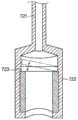
图13是示出根据本发明的一个实施例的以子宫梃子的气囊部为中心的剖面立体图,图14是示出根据本发明的一个实施例的以子宫梃子的第一接合件为中心的剖面示意图,图15是示出根据本发明的一个实施例的子宫梃子的使用例的示意图。13 is a perspective view showing a cross-section centering on the balloon portion of the stile according to one embodiment of the present invention, and FIG. 14 is a cross-sectional view showing a centering on the first engaging member of the stile according to one embodiment of the present invention A schematic diagram, FIG. 15 is a schematic diagram showing an example of use of a uterine stile according to an embodiment of the present invention.
如图13至图15所示,气囊部700可以包括内圈部710、第一膨胀部720及第二膨胀部730。As shown in FIGS. 13 to 15 , the
内圈部710可包括与支承部300的安装槽313结合的安装环711,内圈部710可围绕结合盖部310而向结合盖部310的长度方向延伸。The
第一膨胀部720可以与内圈部710连接,并围绕内圈部710的外周面的一部分。第一膨胀部720上可连接有第一管721,第一管721的一端部连接有第一接合件722。当供应空气的空气供给部(未示出)连接到第一接合件722并供应空气时,空气可通过第一管721供应并填充到第一膨胀部720,以使第一膨胀部720膨胀。The
随着第一膨胀部720膨胀的同时密封阴道10的内侧,由此,在手术过程中切割阴道时,可避免气体通过被切割的阴道泄漏。The inner side of the
第一接合件722的内部可具有止回阀723。止回阀723可以与空气供给部结合。空气供给部可以是注射器,通过空气供给部供应空气时,止回阀723通过空气压力而打开。并且,当通过空气供给部的空气供应被中断时,止回阀723通过第一管721内的空气压力而关闭。The inside of the first engaging
第一膨胀部720膨胀后,第一塞子725堵住止回阀723,以防止空气排出。After the
第二膨胀部730可与内圈部710连接,并围绕内圈部710的外周面的其余部分。第二膨胀部730上可连接有第二管731,第二管731的一端部中可连接有第二接合件732。当供应空气的空气供给部(未示出)连接到第二接合件732并供应空气时,空气可通过第二管731供应并填充到第二膨胀部730,以使第二膨胀部730膨胀。The
随着第二膨胀部730膨胀的同时密封阴道10的内侧,由此,在手术过程中切割阴道时,可避免气体通过被切割的阴道泄漏。第二膨胀部730与第一膨胀部720可独立形成。即,上述气囊部700包括所述第一膨胀部720和所述第二膨胀部730,因此呈双气囊形状。The inner side of the
总之,即使第一膨胀部720和第二膨胀部730中任意一个发生破裂,剩下的另一个仍可防止气体泄漏。第二接合件732的内部也可设有所述止回阀,第二膨胀部730膨胀后,第二塞子735堵住止回阀,以避免空气被排出。In conclusion, even if any one of the
上述本发明的说明仅用于例示,本发明所属领域的普通技术人员可以在不更改本发明的技术思想或必要特征的情况下容易以变形为其他具体形态。因此,如上描述的实施例在所有方面均为例示性而非限制性的。例如,以单一形态进行说明的各组件可以分散实施,同样地,分散说明的组件也可以以结合形态实施。The above description of the present invention is only for illustration, and those of ordinary skill in the art to which the present invention pertains can easily deform it into other specific forms without changing the technical idea or essential features of the present invention. Accordingly, the embodiments described above are illustrative and non-restrictive in all respects. For example, components described in a single form may be implemented in a distributed manner, and similarly, components described in a distributed manner may also be implemented in a combined form.
本发明的范围由权利要求书限定,通过权利要求书的意义、范围及等同概念推导出的所有修改和变形的形态都属于本发明的范围。The scope of the present invention is defined by the claims, and all modifications and deformations derived from the meaning, scope, and equivalent concepts of the claims belong to the scope of the present invention.
Claims (18)
Translated fromChineseApplications Claiming Priority (5)
| Application Number | Priority Date | Filing Date | Title |
|---|---|---|---|
| KR10-2018-0027975 | 2018-03-09 | ||
| KR1020180027975AKR101892728B1 (en) | 2018-03-09 | 2018-03-09 | Uterine manipulator |
| KR20180055255 | 2018-11-27 | ||
| KR30-2018-0055255 | 2018-11-27 | ||
| PCT/KR2019/002630WO2019172664A1 (en) | 2018-03-09 | 2019-03-07 | Uterine elevator |
Publications (1)
| Publication Number | Publication Date |
|---|---|
| CN112040892Atrue CN112040892A (en) | 2020-12-04 |
Family
ID=67846706
Family Applications (1)
| Application Number | Title | Priority Date | Filing Date |
|---|---|---|---|
| CN201980016409.3APendingCN112040892A (en) | 2018-03-09 | 2019-03-07 | uterine splint |
Country Status (3)
| Country | Link |
|---|---|
| US (1) | US12070247B2 (en) |
| CN (1) | CN112040892A (en) |
| WO (1) | WO2019172664A1 (en) |
Families Citing this family (5)
| Publication number | Priority date | Publication date | Assignee | Title |
|---|---|---|---|---|
| CN109907806B (en)* | 2019-04-26 | 2021-04-02 | 大连市妇女儿童医疗中心 | Uterus lifting device |
| CN114903578B (en)* | 2022-05-16 | 2025-07-25 | 王晶 | Medical uterine manipulator |
| CN119344836B (en)* | 2024-10-10 | 2025-07-29 | 中国人民解放军总医院第七医学中心 | Sterile uterine manipulator capable of realizing multi-angle support |
| CN119745486B (en)* | 2025-02-19 | 2025-09-09 | 华中科技大学同济医学院附属协和医院 | A uterine lifting device for gynecological laparoscopic surgery |
| CN120036898A (en)* | 2025-02-24 | 2025-05-27 | 辽宁省肿瘤医院 | Uterine lifting device and automatic uterine lifting system |
Citations (6)
| Publication number | Priority date | Publication date | Assignee | Title |
|---|---|---|---|---|
| US5643285A (en)* | 1994-10-18 | 1997-07-01 | Blairden Precision Instruments, Inc. | Vaginal extender for colpotomy surgery |
| US5662676A (en)* | 1992-06-24 | 1997-09-02 | K.U. Leuven Research & Development | Instrument set for laparoscopic hysterectomy |
| US20070142752A1 (en)* | 2005-12-20 | 2007-06-21 | Robert Kotmel | Uterine cavity length measurement |
| EP2116202A1 (en)* | 2007-02-16 | 2009-11-11 | Marco Antonio Lopez Zepeda | Uterine manipulator for complete removal of human uteri |
| US20100106163A1 (en)* | 2008-10-24 | 2010-04-29 | Coopersurgical, Inc. | Uterine Manipulator Assemblies and Related Components and Methods |
| KR20100122237A (en)* | 2009-05-12 | 2010-11-22 | 박영세 | Uterine manipulator |
Family Cites Families (3)
| Publication number | Priority date | Publication date | Assignee | Title |
|---|---|---|---|---|
| US4016867A (en)* | 1976-04-27 | 1977-04-12 | The United States Of America As Represented By The Secretary Of The Department Of Health, Education And Welfare | Uterine caliper and depth gauge |
| DE102009056705A1 (en) | 2009-12-02 | 2011-06-09 | Richard Wolf Gmbh | uterine manipulator |
| US9717525B2 (en) | 2015-03-17 | 2017-08-01 | Prabhat Kumar Ahluwalia | Uterine manipulator |
- 2019
- 2019-03-07USUS16/975,719patent/US12070247B2/enactiveActive
- 2019-03-07WOPCT/KR2019/002630patent/WO2019172664A1/ennot_activeCeased
- 2019-03-07CNCN201980016409.3Apatent/CN112040892A/enactivePending
Patent Citations (6)
| Publication number | Priority date | Publication date | Assignee | Title |
|---|---|---|---|---|
| US5662676A (en)* | 1992-06-24 | 1997-09-02 | K.U. Leuven Research & Development | Instrument set for laparoscopic hysterectomy |
| US5643285A (en)* | 1994-10-18 | 1997-07-01 | Blairden Precision Instruments, Inc. | Vaginal extender for colpotomy surgery |
| US20070142752A1 (en)* | 2005-12-20 | 2007-06-21 | Robert Kotmel | Uterine cavity length measurement |
| EP2116202A1 (en)* | 2007-02-16 | 2009-11-11 | Marco Antonio Lopez Zepeda | Uterine manipulator for complete removal of human uteri |
| US20100106163A1 (en)* | 2008-10-24 | 2010-04-29 | Coopersurgical, Inc. | Uterine Manipulator Assemblies and Related Components and Methods |
| KR20100122237A (en)* | 2009-05-12 | 2010-11-22 | 박영세 | Uterine manipulator |
Also Published As
| Publication number | Publication date |
|---|---|
| WO2019172664A1 (en) | 2019-09-12 |
| US12070247B2 (en) | 2024-08-27 |
| US20210000507A1 (en) | 2021-01-07 |
Similar Documents
| Publication | Publication Date | Title |
|---|---|---|
| CN112040892A (en) | uterine splint | |
| US11986216B2 (en) | Uterine manipulator with adjustable cervical cup | |
| US7105007B2 (en) | Cervical medical device, system and method | |
| ES2920509T3 (en) | cannula assembly | |
| JP2011092745A5 (en) | ||
| US9055973B2 (en) | Device to assist in cesarean section | |
| US20160183977A1 (en) | Device for placement of an intrauterine balloon | |
| JP2015165977A (en) | Intra-vaginal device for fecal incontinence | |
| WO2012137894A1 (en) | Hemostatic tool, hemostatic device, and hemostatic method for uterine bleeding | |
| ES2358628T3 (en) | INFLATABLE MEDICAL DEVICE | |
| US12213702B2 (en) | Fetus delivery assisting device | |
| CN113286553A (en) | Uterine dilator device | |
| JP6068618B2 (en) | Vaginal internal support and vaginal internal support set | |
| US20230060850A1 (en) | Device for reduction or prevention of preterm labor | |
| KR20180008718A (en) | Device for protecting the pelvic floor during vaginal delivery | |
| JP2012533358A (en) | Balloon catheter for use with a surgical coring system | |
| JP2008506490A (en) | Obstetric suction dispenser | |
| US20230389960A1 (en) | Expandable pneumo-occluder with sealable instrument port | |
| WO2014162363A1 (en) | Intravaginal support tool and fluid injection device | |
| KR101892728B1 (en) | Uterine manipulator | |
| CN110603011A (en) | Inflatable penile prosthesis with reinforcement member | |
| CN111601557B (en) | Device for partially isolating target biological structures | |
| CN222815845U (en) | Balloon structure for hysterectomy and uterine lifting forceps | |
| CN109718460B (en) | Esophageal dilator | |
| CN221635980U (en) | Oviduct recanalization device |
Legal Events
| Date | Code | Title | Description |
|---|---|---|---|
| PB01 | Publication | ||
| PB01 | Publication | ||
| SE01 | Entry into force of request for substantive examination | ||
| SE01 | Entry into force of request for substantive examination | ||
| WD01 | Invention patent application deemed withdrawn after publication | ||
| WD01 | Invention patent application deemed withdrawn after publication | Application publication date:20201204 |