CN112040885A - Knitted tissue scaffold - Google Patents
Knitted tissue scaffoldDownload PDFInfo
- Publication number
- CN112040885A CN112040885ACN201980027115.0ACN201980027115ACN112040885ACN 112040885 ACN112040885 ACN 112040885ACN 201980027115 ACN201980027115 ACN 201980027115ACN 112040885 ACN112040885 ACN 112040885A
- Authority
- CN
- China
- Prior art keywords
- fibers
- fiber
- zone
- tissue
- scaffold
- Prior art date
- Legal status (The legal status is an assumption and is not a legal conclusion. Google has not performed a legal analysis and makes no representation as to the accuracy of the status listed.)
- Pending
Links
- 239000002407tissue scaffoldSubstances0.000titledescription2
- 239000000835fiberSubstances0.000claimsdescription274
- 229920001577copolymerPolymers0.000claimsdescription35
- AEMRFAOFKBGASW-UHFFFAOYSA-NGlycolic acidChemical compoundOCC(O)=OAEMRFAOFKBGASW-UHFFFAOYSA-N0.000claimsdescription29
- 125000006850spacer groupChemical group0.000claimsdescription23
- RKDVKSZUMVYZHH-UHFFFAOYSA-N1,4-dioxane-2,5-dioneChemical compoundO=C1COC(=O)CO1RKDVKSZUMVYZHH-UHFFFAOYSA-N0.000claimsdescription18
- JVTAAEKCZFNVCJ-UHFFFAOYSA-Nlactic acidChemical compoundCC(O)C(O)=OJVTAAEKCZFNVCJ-UHFFFAOYSA-N0.000claimsdescription16
- 229920000642polymerPolymers0.000claimsdescription15
- 229920000954PolyglycolidePolymers0.000claimsdescription13
- JJTUDXZGHPGLLC-UHFFFAOYSA-NlactideChemical compoundCC1OC(=O)C(C)OC1=OJJTUDXZGHPGLLC-UHFFFAOYSA-N0.000claimsdescription13
- YFHICDDUDORKJB-UHFFFAOYSA-Ntrimethylene carbonateChemical compoundO=C1OCCCO1YFHICDDUDORKJB-UHFFFAOYSA-N0.000claimsdescription11
- 229920000747poly(lactic acid)Polymers0.000claimsdescription10
- JJTUDXZGHPGLLC-IMJSIDKUSA-N4511-42-6Chemical compoundC[C@@H]1OC(=O)[C@H](C)OC1=OJJTUDXZGHPGLLC-IMJSIDKUSA-N0.000claimsdescription7
- 229920002463poly(p-dioxanone) polymerPolymers0.000claimsdescription7
- 239000000622polydioxanoneSubstances0.000claimsdescription7
- PAPBSGBWRJIAAV-UHFFFAOYSA-Nε-CaprolactoneChemical compoundO=C1CCCCCO1PAPBSGBWRJIAAV-UHFFFAOYSA-N0.000claimsdescription7
- 235000014655lactic acidNutrition0.000claimsdescription6
- 239000004310lactic acidSubstances0.000claimsdescription6
- 229920001432poly(L-lactide)Polymers0.000claimsdescription6
- 229920001610polycaprolactonePolymers0.000claimsdescription6
- 239000004632polycaprolactoneSubstances0.000claimsdescription6
- VPVXHAANQNHFSF-UHFFFAOYSA-N1,4-dioxan-2-oneChemical compoundO=C1COCCO1VPVXHAANQNHFSF-UHFFFAOYSA-N0.000claimsdescription5
- 239000005014poly(hydroxyalkanoate)Substances0.000claimsdescription5
- 229920000903polyhydroxyalkanoatePolymers0.000claimsdescription5
- 229920000166polytrimethylene carbonatePolymers0.000claimsdescription5
- 239000011800void materialSubstances0.000claimsdescription5
- 238000000034methodMethods0.000abstractdescription23
- 238000000429assemblyMethods0.000abstractdescription4
- 230000000712assemblyEffects0.000abstractdescription4
- 238000004519manufacturing processMethods0.000abstractdescription4
- 238000010304firingMethods0.000description40
- 239000000463materialSubstances0.000description36
- 230000009477glass transitionEffects0.000description22
- -1poly(lactic acid)Polymers0.000description19
- 238000009940knittingMethods0.000description12
- 238000005520cutting processMethods0.000description7
- LCSKNASZPVZHEG-UHFFFAOYSA-N3,6-dimethyl-1,4-dioxane-2,5-dione;1,4-dioxane-2,5-dioneChemical groupO=C1COC(=O)CO1.CC1OC(=O)C(C)OC1=OLCSKNASZPVZHEG-UHFFFAOYSA-N0.000description6
- 230000006835compressionEffects0.000description6
- 238000007906compressionMethods0.000description6
- 230000015556catabolic processEffects0.000description5
- 238000006731degradation reactionMethods0.000description5
- 238000002513implantationMethods0.000description5
- IJGRMHOSHXDMSA-UHFFFAOYSA-NAtomic nitrogenChemical compoundN#NIJGRMHOSHXDMSA-UHFFFAOYSA-N0.000description4
- 206010061218InflammationDiseases0.000description4
- 210000004204blood vesselAnatomy0.000description4
- 230000001413cellular effectEffects0.000description4
- 238000009826distributionMethods0.000description4
- 230000004054inflammatory processEffects0.000description4
- 238000001878scanning electron micrographMethods0.000description4
- 238000001356surgical procedureMethods0.000description4
- 238000006073displacement reactionMethods0.000description3
- 230000035876healingEffects0.000description3
- 208000015181infectious diseaseDiseases0.000description3
- 210000002540macrophageAnatomy0.000description3
- 238000000399optical microscopyMethods0.000description3
- 229920001606poly(lactic acid-co-glycolic acid)Polymers0.000description3
- 229920005594polymer fiberPolymers0.000description3
- WZUVPPKBWHMQCE-UHFFFAOYSA-NHaematoxylinChemical compoundC12=CC(O)=C(O)C=C2CC2(O)C1C1=CC=C(O)C(O)=C1OC2WZUVPPKBWHMQCE-UHFFFAOYSA-N0.000description2
- KFZMGEQAYNKOFK-UHFFFAOYSA-NIsopropanolChemical compoundCC(C)OKFZMGEQAYNKOFK-UHFFFAOYSA-N0.000description2
- 210000004369bloodAnatomy0.000description2
- 239000008280bloodSubstances0.000description2
- 238000004140cleaningMethods0.000description2
- 150000002148estersChemical class0.000description2
- 239000012530fluidSubstances0.000description2
- 239000007943implantSubstances0.000description2
- 230000002757inflammatory effectEffects0.000description2
- 229910052757nitrogenInorganic materials0.000description2
- 239000011148porous materialSubstances0.000description2
- 230000005483Hooke's lawEffects0.000description1
- 206010020772HypertensionDiseases0.000description1
- 206010029113NeovascularisationDiseases0.000description1
- 241000283973Oryctolagus cuniculusSpecies0.000description1
- 230000004913activationEffects0.000description1
- 230000002411adverseEffects0.000description1
- 230000003872anastomosisEffects0.000description1
- 210000003484anatomyAnatomy0.000description1
- 238000000137annealingMethods0.000description1
- 230000009286beneficial effectEffects0.000description1
- 230000015572biosynthetic processEffects0.000description1
- 230000036772blood pressureEffects0.000description1
- 230000036760body temperatureEffects0.000description1
- 239000006227byproductSubstances0.000description1
- 210000004027cellAnatomy0.000description1
- 230000008859changeEffects0.000description1
- 239000011248coating agentSubstances0.000description1
- 238000000576coating methodMethods0.000description1
- 238000010276constructionMethods0.000description1
- 238000001816coolingMethods0.000description1
- 230000001351cycling effectEffects0.000description1
- 230000003247decreasing effectEffects0.000description1
- 230000000881depressing effectEffects0.000description1
- 230000000994depressogenic effectEffects0.000description1
- 238000013461designMethods0.000description1
- 238000010586diagramMethods0.000description1
- YQGOJNYOYNNSMM-UHFFFAOYSA-NeosinChemical compound[Na+].OC(=O)C1=CC=CC=C1C1=C2C=C(Br)C(=O)C(Br)=C2OC2=C(Br)C(O)=C(Br)C=C21YQGOJNYOYNNSMM-UHFFFAOYSA-N0.000description1
- 238000000605extractionMethods0.000description1
- 239000011888foilSubstances0.000description1
- 230000002496gastric effectEffects0.000description1
- 238000010438heat treatmentMethods0.000description1
- 238000001727in vivoMethods0.000description1
- 238000003780insertionMethods0.000description1
- 230000037431insertionEffects0.000description1
- 230000010354integrationEffects0.000description1
- 230000003993interactionEffects0.000description1
- 210000000265leukocyteAnatomy0.000description1
- 239000011159matrix materialSubstances0.000description1
- 238000005259measurementMethods0.000description1
- 239000000203mixtureSubstances0.000description1
- 238000012986modificationMethods0.000description1
- 230000004048modificationEffects0.000description1
- 210000000651myofibroblastAnatomy0.000description1
- 239000013307optical fiberSubstances0.000description1
- 230000000149penetrating effectEffects0.000description1
- 230000002028prematureEffects0.000description1
- 238000012545processingMethods0.000description1
- 230000001737promoting effectEffects0.000description1
- 238000011084recoveryMethods0.000description1
- 238000007634remodelingMethods0.000description1
- 230000008439repair processEffects0.000description1
- 230000004044responseEffects0.000description1
- 230000000250revascularizationEffects0.000description1
- 210000002784stomachAnatomy0.000description1
- 210000001835visceraAnatomy0.000description1
- 239000002699waste materialSubstances0.000description1
Images


Landscapes
- Materials For Medical Uses (AREA)
- Surgical Instruments (AREA)
Abstract
Description
Translated fromChinese技术领域technical field
本发明提供了针织组织支架及其制造方法。The present invention provides a knitted tissue scaffold and a manufacturing method thereof.
背景技术Background technique
外科缝合器用于外科手术中,以闭合在特定手术中所涉及的组织、血管、导管、分流管、或者其他对象或身体部分中的开口。这些开口可为天然存在的,诸如血管或类似于胃的内部器官中的通路,或者它们可为在外科手术期间由外科医生形成的,诸如通过穿刺组织或血管以形成旁路或吻合部或通过在缝合手术期间切割组织。Surgical staplers are used in surgical procedures to close openings in tissue, blood vessels, catheters, shunts, or other objects or body parts involved in a particular procedure. These openings may be naturally occurring, such as passages in blood vessels or internal organs like the stomach, or they may be formed by the surgeon during surgical procedures, such as by puncturing tissue or blood vessels to create bypasses or anastomosis or through Tissue is cut during the suturing procedure.
一些外科缝合器需要外科医生为正被缝合的组织选择具有适当钉高度的适当钉。例如,外科医生可选择用于厚组织的长钉和用于薄组织的短钉。然而,在一些情况下,正被缝合的组织不具有一致的厚度,因此,钉不能在每个钉部位处实现期望的击发构型。因此,不能在所有缝合部位处或附近形成期望的密封,从而允许血液、空气、胃肠液和其他流体通过未密封部位渗出。Some surgical staplers require the surgeon to select the appropriate staples with the appropriate staple height for the tissue being stapled. For example, a surgeon may choose long staples for thick tissue and short staples for thin tissue. However, in some cases, the tissue being stapled does not have a consistent thickness and, therefore, the staples cannot achieve the desired fired configuration at each staple site. As a result, the desired seal cannot be formed at or near all suture sites, allowing blood, air, gastrointestinal fluids, and other fluids to seep through the unsealed site.
另外,可结合类似于缝合的手术来植入的钉以及其他物体和材料通常缺乏它们所植入的组织的一些特征。例如,钉以及其他物体和材料可缺乏它们所植入的组织的天然柔韧性,因此不能承受植入部位处的变化的组织内压力。这可导致不期望的组织撕裂,并因此导致在钉部位处或附近的渗漏,以及/或者在并置的植入物和组织之间的渗漏。Additionally, staples and other objects and materials that can be implanted in conjunction with procedures like suturing often lack some of the characteristics of the tissue into which they are implanted. For example, staples and other objects and materials may lack the natural flexibility of the tissue into which they are implanted, and thus cannot withstand varying intra-tissue pressures at the implant site. This can lead to undesired tissue tearing and thus leakage at or near the staple site, and/or leakage between the apposed implant and tissue.
因此,仍然需要用于解决外科缝合器的当前问题的改进的器械和方法。Accordingly, there remains a need for improved instruments and methods for addressing current problems with surgical staplers.
发明内容SUMMARY OF THE INVENTION
提供了与外科缝合器械一起使用的钉仓组件。A staple cartridge assembly is provided for use with a surgical stapling instrument.
在一个示例性实施方案中,所述钉仓组件可包括:钉仓,所述钉仓具有多个钉和仓平台;以及针织的能够弹性变形的、能够生物吸收的支架,所述支架附接到所述仓平台并且由至少三个各自具有不同功能的不同区形成,其中所述钉能够穿过所述支架部署到抵靠所述支架捕获的组织中。所述支架可包括:第一针织区,所述第一针织区可被构造成能够促进组织向内生长;第二针织区,所述第二针织区可被构造成能够适形(conformable)以便附接到所述仓平台;以及间隔区,所述间隔区设置在所述第一针织区和所述第二针织区之间并且可被构造成能够支撑所述第一针织区和所述第二针织区,其中在所述第一针织区和所述第二针织区中存在开口,并且在所述间隔区中存在空隙,其中所述空隙大于所述开口。所述第一针织区可包含由第一能够生物吸收的聚合物制成的第一纤维和由第二能够生物吸收的聚合物制成的第二纤维,其中每个第一纤维的纤维直径小于每个第二纤维的纤维直径。所述第二针织区可包含所述第一针织区的所述第一纤维和所述第二纤维。所述间隔区可由所述第二纤维形成,其中所述第二纤维非固定地且能够滑动地互连到所述第一针织区的所述第一纤维和所述第二针织区的所述第一纤维。在一个方面,所述支架可被构造成能够当所述支架处于组织部署状态时对所捕获的组织施加至少约3g/mm2的应力达至少3天。In an exemplary embodiment, the staple cartridge assembly can include: a staple cartridge having a plurality of staples and a cartridge platform; and a knitted elastically deformable, bioabsorbable scaffold to which the scaffold is attached to the cartridge platform and formed by at least three distinct regions each having a different function, wherein the staples are deployable through the stent into tissue captured against the stent. The stent can include: a first knitted zone that can be configured to promote tissue ingrowth; a second knitted zone that can be configured to be conformable to attached to the bin deck; and a spacer region disposed between the first knitting zone and the second knitting zone and can be configured to support the first knitting zone and the second knitting zone Two knit zones, wherein openings are present in the first and second knit zones, and voids are present in the spacer zones, wherein the voids are larger than the openings. The first knitted zone may comprise first fibers made of a first bioabsorbable polymer and second fibers made of a second bioabsorbable polymer, wherein each first fiber has a fiber diameter less than The fiber diameter of each second fiber. The second knitted zone may comprise the first fibers and the second fibers of the first knitted zone. The spacers may be formed from the second fibers, wherein the second fibers are non-fixably and slidably interconnected to the first fibers of the first knitted zone and the second knitted zone first fiber. In one aspect, the scaffold can be configured to apply a stress of at least about 3 g/mm2 to captured tissue for at least 3 days when the scaffold is in a tissue-deployed state.
在一些方面,所述第一纤维的纤维直径可为所述第二纤维的纤维直径的约1/5至1/20。在其他方面,所述第一纤维的纤维直径可为所述第二纤维的纤维直径的约1/10。In some aspects, the fiber diameter of the first fibers may be about 1/5 to 1/20 the fiber diameter of the second fibers. In other aspects, the fiber diameter of the first fibers may be about 1/10 the fiber diameter of the second fibers.
在一个方面,所述第二纤维可从所述第一针织区延伸到所述第二针织区,使得所述第二纤维横跨所述间隔区延伸,并且所述间隔区内的所述第二纤维的至少一部分可被取向成基本上垂直于所述第一针织区的所述第一纤维和所述第二针织区的所述第一纤维。In one aspect, the second fibers may extend from the first knitted zone to the second knitted zone such that the second fibers extend across the spacer zone and the first fibers within the spacer zone At least a portion of the two fibers may be oriented substantially perpendicular to the first fibers of the first knitting zone and the first fibers of the second knitting zone.
所述第一类型的纤维和所述第二类型的纤维可由多种材料形成。在一个方面,所述第一类型的纤维可由以下中的至少一种形成:聚-L-乳酸,乙交酯和L-丙交酯的共聚物,乙醇酸和乳酸的共聚物,聚(乳酸)聚(乳酸-羟基乙酸共聚物),聚(乳酸),聚乙交酯,以及乙交酯、己内酯、三亚甲基碳酸酯和丙交酯的共聚物。在另一方面,所述第二类型的纤维可由以下中的至少一种形成:聚二氧六环酮,聚二氧六环酮和聚乙交酯的共聚物,丙交酯和聚己内酯的共聚物,乙交酯、二氧环己酮和三亚甲基碳酸酯的共聚物,聚(三亚甲基碳酸酯),聚羟基链烷酸酯以及聚葡糖酸酯。The fibers of the first type and the fibers of the second type may be formed from a variety of materials. In one aspect, the first type of fibers may be formed from at least one of the following: poly-L-lactic acid, copolymers of glycolide and L-lactide, copolymers of glycolic acid and lactic acid, poly(lactic acid) ) poly(lactic-co-glycolic acid), poly(lactic acid), polyglycolide, and copolymers of glycolide, caprolactone, trimethylene carbonate and lactide. In another aspect, the second type of fibers may be formed from at least one of the following: polydioxane, copolymers of polydioxane and polyglycolide, lactide and polycaprolactone Copolymers of esters, copolymers of glycolide, dioxanone and trimethylene carbonate, poly(trimethylene carbonate), polyhydroxyalkanoates and polygluconates.
在另一个实施方案中,提供了钉仓组件,并且所述钉仓组件可包括:钉仓,所述钉仓具有多个钉和仓平台;以及针织的能够弹性变形的、能够生物吸收的支架,所述支架附接到所述仓平台并且由至少三个各自具有不同功能的不同区形成,其中所述钉能够穿过所述支架部署到抵靠所述支架捕获的组织中。所述支架可包括第一区,所述第一区可具有针织结构并且可被构造成能够促进组织向内生长,其中所述第一区包含由第一能够生物吸收的聚合物制成的第一纤维。所述支架还可包括第二区,所述第二区可由第二纤维形成,所述第二纤维由第二能够生物吸收的聚合物制成,并且所述第二区可被构造成能够竖直地支撑所述第一区,其中所述第二纤维非固定地且能够滑动地互连到所述第一区的所述第一纤维,使得所述第二纤维在所述第二区内基本上竖直地取向。每个第一纤维的纤维直径可小于每个第二纤维的纤维直径,并且其中在所述第一区中存在开口,并且在所述第二区中存在空隙,其中所述空隙大于所述开口。In another embodiment, a staple cartridge assembly is provided and can include: a staple cartridge having a plurality of staples and a cartridge platform; and a knitted elastically deformable, bioabsorbable scaffold , the stent is attached to the cartridge platform and is formed of at least three distinct regions each having a different function, wherein the staples are deployable through the stent into tissue captured against the stent. The scaffold can include a first region that can have a knitted structure and can be configured to promote tissue ingrowth, wherein the first region comprises a first region made of a first bioabsorbable polymer. a fiber. The stent can further include a second region, the second region can be formed from second fibers, the second fibers are made of a second bioabsorbable polymer, and the second region can be configured to stand supporting the first zone straight, wherein the second fibers are non-fixably and slidably interconnected to the first fibers of the first zone such that the second fibers are within the second zone Oriented substantially vertically. The fiber diameter of each first fiber may be smaller than the fiber diameter of each second fiber, and wherein openings are present in the first zone, and voids are present in the second zone, wherein the voids are larger than the openings .
在一些方面,所述支架还可包括第三区,所述第三区可具有针织结构并且可被构造成能够适形以便附接到所述仓平台,其中所述第三区可包含所述第一纤维,并且所述第二区可位于所述第一区与所述第三区之间。在此类情况下,所述第二纤维可非固定地且能够滑动地互连到所述第三区的所述第一纤维,其中所述第二纤维可从所述第一区延伸到所述第三区,使得所述第二纤维的至少一部分在所述第二区内竖直地取向。所述支架可被构造成能够当所述支架处于组织部署状态时对所捕获的组织施加至少约3g/mm2的应力达至少3天。In some aspects, the stent can also include a third region that can have a knitted structure and can be configured to conform for attachment to the cartridge deck, wherein the third region can contain the the first fiber, and the second zone may be located between the first zone and the third zone. In such cases, the second fibers may be non-fixedly and slidably interconnected to the first fibers of the third zone, wherein the second fibers may extend from the first zone to all the The third zone is such that at least a portion of the second fibers are vertically oriented within the second zone. The scaffold can be configured to apply a stress of at least about 3 g/mm2 to captured tissue for at least 3 days when the scaffold is in a tissue-deployed state.
在一些方面,所述第一纤维的纤维直径可为所述第二纤维的纤维直径的约1/5至1/20。在其他方面,所述第一纤维的纤维直径可为所述第二纤维的纤维直径的约1/10。In some aspects, the fiber diameter of the first fibers may be about 1/5 to 1/20 the fiber diameter of the second fibers. In other aspects, the fiber diameter of the first fibers may be about 1/10 the fiber diameter of the second fibers.
所述第一类型的纤维和所述第二类型的纤维可由多种材料形成。在一个方面,所述第一类型的纤维可由以下中的至少一种形成:聚-L-乳酸,乙交酯和L-丙交酯的共聚物,乙醇酸和乳酸的共聚物,聚(乳酸)聚(乳酸-羟基乙酸共聚物),聚(乳酸),聚乙交酯,以及乙交酯、己内酯、三亚甲基碳酸酯和丙交酯的共聚物。在另一方面,所述第二类型的纤维可由以下中的至少一种形成:聚二氧六环酮,聚二氧六环酮和聚乙交酯的共聚物,丙交酯和聚己内酯的共聚物,乙交酯、二氧环己酮和三亚甲基碳酸酯的共聚物,聚(三亚甲基碳酸酯),聚羟基链烷酸酯以及聚葡糖酸酯。The fibers of the first type and the fibers of the second type may be formed from a variety of materials. In one aspect, the first type of fibers may be formed from at least one of the following: poly-L-lactic acid, copolymers of glycolide and L-lactide, copolymers of glycolic acid and lactic acid, poly(lactic acid) ) poly(lactic-co-glycolic acid), poly(lactic acid), polyglycolide, and copolymers of glycolide, caprolactone, trimethylene carbonate and lactide. In another aspect, the second type of fibers may be formed from at least one of the following: polydioxane, copolymers of polydioxane and polyglycolide, lactide and polycaprolactone Copolymers of esters, copolymers of glycolide, dioxanone and trimethylene carbonate, poly(trimethylene carbonate), polyhydroxyalkanoates and polygluconates.
提供了与外科钉仓一起使用的支架,并且所述支架可包括:第一针织区,所述第一针织区被构造成能够促进组织向内生长;第二针织区,所述第二针织区被构造成能够适形以便附接到仓平台;以及间隔区,所述间隔区设置在所述第一针织区和所述第二针织区之间并且被构造成能够支撑所述第一针织区和所述第二针织区,其中在所述第一针织区和所述第二针织区中存在开口,并且在所述间隔区中存在空隙,其中所述空隙大于所述开口。所述第一针织区可包含由第一能够生物吸收的聚合物制成的第一纤维和由第二能够生物吸收的聚合物制成的第二纤维,其中每个第一纤维的纤维直径小于每个第二纤维的纤维直径。所述第二针织区可包含所述第一针织区的所述第一纤维和所述第二纤维。所述间隔区可由所述第二纤维形成,其中所述第二纤维可非固定地且能够滑动地互连到所述第一针织区的所述第一纤维和所述第二针织区的所述第一纤维。A scaffold for use with a surgical staple cartridge is provided and can include: a first knitted zone configured to promote tissue ingrowth; a second knitted zone, the second knitted zone configured to be conformable for attachment to a bin deck; and a spacer region disposed between the first knitted zone and the second knitted zone and configured to support the first knitted zone and the second knitting zone, wherein openings are present in the first knitting zone and the second knitting zone, and voids are present in the spacer zones, wherein the voids are larger than the openings. The first knitted zone may comprise first fibers made of a first bioabsorbable polymer and second fibers made of a second bioabsorbable polymer, wherein each first fiber has a fiber diameter less than The fiber diameter of each second fiber. The second knitted zone may comprise the first fibers and the second fibers of the first knitted zone. The spacers may be formed from the second fibers, wherein the second fibers are non-fixably and slidably interconnected to the first fibers of the first knitted zone and all of the second knitted zone. the first fiber.
附图说明Description of drawings
本专利或专利申请文件包含至少一张绘制成彩色的附图。在提出请求并且支付必要的费用后,美国专利和商标局将会提供本专利或专利申请公开的带彩图副本。The patent or patent application file contains at least one drawing executed in color. Copies of this patent or patent application publication with color drawing will be provided by the US Patent and Trademark Office upon request and payment of the necessary fee.
通过以下结合附图所作的详细描述,将更充分地理解本发明,在附图中:The present invention will be more fully understood from the following detailed description in conjunction with the accompanying drawings, in which:
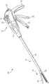
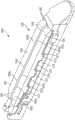
图1为常规外科缝合和切断器械的一个示例性实施方案的透视图;1 is a perspective view of an exemplary embodiment of a conventional surgical stapling and severing instrument;
图2为图1的外科缝合和切断器械的钉仓的楔形滑动件的透视图;2 is a perspective view of a wedge slide of the staple cartridge of the surgical stapling and severing instrument of FIG. 1;
图3为图1的外科缝合和切断器械的刀和击发杆(“E形梁”)的透视图;Figure 3 is a perspective view of the knife and firing rod ("E-beam") of the surgical stapling and severing instrument of Figure 1;
图4为可设置在图1的缝合和切断器械内的外科仓的纵向剖面图;Figure 4 is a longitudinal cross-sectional view of a surgical cartridge that may be positioned within the stapling and severing instrument of Figure 1;
图5为可设置在图4的外科仓组件的钉仓内处于未击发(预部署)构型的钉的顶视图;5 is a top view of staples that may be disposed within the staple cartridge of the surgical cartridge assembly of FIG. 4 in an unfired (pre-deployed) configuration;
图6为具有附接到仓平台的支架的外科仓组件的示例性实施方案的纵向剖面图;6 is a longitudinal cross-sectional view of an exemplary embodiment of a surgical cartridge assembly with a stent attached to a cartridge platform;
图7为示出当缝合到组织时图6的支架的示意图;FIG. 7 is a schematic diagram showing the scaffold of FIG. 6 when sutured to tissue;
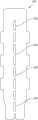
图8A为可附接到图6的外科仓组件的仓平台的支架的示例性实施方案的放大顶视图;8A is an enlarged top view of an exemplary embodiment of a bracket attachable to the cartridge platform of the surgical cartridge assembly of FIG. 6;
图8B为图8A的支架在B-B处截取的放大剖视图;8B is an enlarged cross-sectional view of the stent of FIG. 8A taken at B-B;
图8C为图8A的支架在C-C处截取的另一个放大剖视图;Figure 8C is another enlarged cross-sectional view of the stent of Figure 8A taken at C-C;
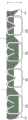
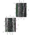
图9为图8A至图8C中支架在500μm尺度下的扫描电子显微图(SEM)图像;9 is a scanning electron micrograph (SEM) image of the scaffold in FIGS. 8A-8C at a scale of 500 μm;
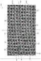
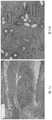
图10A为如实施例2中讨论的在60天移除的植入支架的组织病理学图像。10A is a histopathological image of the implanted scaffold removed at 60 days as discussed in Example 2. FIG.
图10B为图10A的节段10B的放大视图;Figure 10B is an enlarged view of
图11A为如实施例2中讨论的在90天移除的植入支架的组织病理学图像;11A is a histopathological image of the implanted scaffold removed at 90 days as discussed in Example 2;
图11B为图11A的节段11B的放大视图;Figure 11B is an enlarged view of
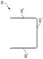
图12A为支架的另一个示例性实施方案的透视图;12A is a perspective view of another exemplary embodiment of a stent;
图12B为具有附接到仓平台的图12A所示支架的钉仓组件的另一个示例性实施方案;并且Figure 12B is another exemplary embodiment of a staple cartridge assembly having the bracket shown in Figure 12A attached to the cartridge deck; and
图13为支架的另一个示例性实施方案的底视图。13 is a bottom view of another exemplary embodiment of a stent.
具体实施方式Detailed ways
现在将描述某些示例性实施方案,以提供对本文所公开的器械和方法的结构、功能、制造和用途的原理的全面理解。这些实施方案的一个或多个示例在附图中示出。本领域的技术人员将会理解,在本文中具体描述的和在附图中示出的器械、系统和方法是非限制性的示例性实施方案,并且本发明的范围仅由权利要求书限定。结合一个示例性实施方案示出或描述的特征部可与其他实施方案的特征部进行组合。此类修改和变型旨在包括在本发明的范围之内。Certain exemplary embodiments will now be described in order to provide a thorough understanding of the principles of structure, function, manufacture, and use of the devices and methods disclosed herein. One or more examples of these embodiments are illustrated in the accompanying drawings. Those skilled in the art will appreciate that the instruments, systems and methods specifically described herein and illustrated in the accompanying drawings are non-limiting exemplary embodiments and that the scope of the present invention is limited only by the claims. Features shown or described in connection with one exemplary embodiment may be combined with features of other embodiments. Such modifications and variations are intended to be included within the scope of the present invention.
此外,在本公开中,各实施方案中名称相似的部件通常具有类似的特征部,因此在具体实施方案中,不一定完整地阐述每个名称相似的部件的每个特征部。另外,在所公开的系统、器械和方法的描述中使用线性或圆形尺寸的程度上,此类尺寸并非旨在限制可结合此类系统、器械和方法使用的形状的类型。本领域中技术人员将认识到,针对任何几何形状可容易地确定此类线性和圆形尺寸的等效尺寸。系统和器械及其部件的尺寸和形状可至少取决于该系统和器械将用于其中的受治疗者的解剖结构、该系统和器械将与其一起使用的部件的尺寸和形状、以及该系统和器械将用于其中的方法和手术。Furthermore, in the present disclosure, like-named components in various embodiments generally have similar features, and thus each feature of each like-named component is not necessarily fully described in specific embodiments. Additionally, to the extent that linear or circular dimensions are used in the description of the disclosed systems, instruments and methods, such dimensions are not intended to limit the types of shapes that may be used in connection with such systems, instruments and methods. Those skilled in the art will recognize that equivalent dimensions of such linear and circular dimensions can be readily determined for any geometric shape. The size and shape of the system and device and its components may depend at least on the anatomy of the subject in which the system and device will be used, the size and shape of the components with which the system and device will be used, and the The methods and procedures that will be used in it.
应当理解,本文相对于抓握器械柄部的使用者诸如临床医生来使用术语“近侧”和“远侧”。诸如“前”和“后”的其他空间术语分别类似地对应于远侧和近侧。还应当理解,为便利和清楚起见,本文结图示使用空间用语诸如“竖直”和“水平”。然而,外科器械在许多取向和位置上使用,并且这些空间术语并非限制性和绝对的。It should be understood that the terms "proximal" and "distal" are used herein with respect to a user grasping the handle of the instrument, such as a clinician. Other spatial terms such as "anterior" and "posterior" similarly correspond to distal and proximal, respectively. It should also be understood that, for convenience and clarity, spatial terms such as "vertical" and "horizontal" are used in the illustrations herein. However, surgical instruments are used in many orientations and positions, and these spatial terms are not limiting and absolute.
在本文中,值或范围可表示为“约”和/或从“约”一个特定值至另一个特定值。当表示此类值或范围时,所公开的其他实施方案包括所列举的特定值和/或从一个特定值到另一个特定值。类似地,当通过使用先行词“约”将值表示为近似值时,应当理解,本文公开了许多值,并且特定值形成另一个实施方案。还应当理解,其中公开了许多值,并且每个值在本文中也被公开为除了值本身之外的“约”该特定值。在实施方案中,“约”能够用于表示例如在所列举值的10%内,在所列举值的5%内或所列举值的2%内。Values or ranges may be expressed herein as "about" and/or from "about" one particular value to another particular value. When such values or ranges are expressed, other embodiments disclosed include the particular value recited and/or from one particular value to another. Similarly, when values are expressed as approximations, by use of the antecedent "about," it will be understood that many values are disclosed herein, and that the particular value forms another embodiment. It should also be understood that a number of values are disclosed therein, and that each value is also disclosed herein as "about" the particular value, in addition to the value itself. In embodiments, "about" can be used to mean, for example, within 10% of the recited value, within 5% of the recited value, or within 2% of the recited value.
为了描述和限定本教导内容,注意除非另外指明,否则本文使用术语“基本上”来表示可表征任何定量的比较、值、测量、或其他表示的固有的不确定度。术语“基本上”在本文中也可用来表示定量表示可相对于所声明的参考发生变化而不会导致所关注的主题的基本功能发生变化的程度。For the purpose of describing and defining the present teachings, it is noted that unless otherwise indicated, the term "substantially" is used herein to refer to the inherent uncertainty that can characterize any quantitative comparison, value, measurement, or other representation. The term "substantially" may also be used herein to denote the degree to which a quantitative representation can be changed relative to the stated reference without resulting in a change in the basic function of the subject matter concerned.
本发明提供了外科钉仓组件及其制造方法。一般来讲,提供了具有钉仓的钉仓组件,该钉仓包括其中设置有多个钉的仓平台。该钉仓组件还包括针织的能够弹性变形的、能够生物吸收的支架,该支架被构造成能够与仓平台能够释放地配合并且允许钉穿过支架部署到组织中。该支架可与仓平台能够释放地配合,使得当钉从仓平台部署到组织中时,支架的至少一部分可附接到由该钉捕获的组织。如本文所述,支架可被构造成能够补偿组织属性的变化,诸如组织厚度的变化,并且/或者在支架缝合到组织时促进组织向内生长。例如,支架可被构造成能够当处于组织部署状态时(例如,当支架缝合到体内组织时)对组织施加至少约3g/mm2的应力达至少3天。示例性钉仓组件可包括多个特征部以方便外科钉的施加,如本文所述和附图中所示。然而,本领域的技术人员将会知道,钉仓组件可仅包括这些特征部中的一些特征部并且/或者该钉仓组件可包括本领域已知的多种其他特征部。本文所述的钉仓组件仅旨在表示某些示例性实施方案。此外,虽然结合外科钉仓组件描述了支架,但支架可与任何类型的外科器械结合使用。The present invention provides surgical staple cartridge assemblies and methods of making the same. In general, a staple cartridge assembly is provided having a staple cartridge that includes a cartridge deck having a plurality of staples disposed therein. The staple cartridge assembly also includes a knitted elastically deformable, bioabsorbable scaffold configured to releasably mate with the cartridge platform and allow staples to be deployed through the scaffold into tissue. The stent can be releasably engaged with the cartridge platform such that when the staples are deployed from the cartridge platform into tissue, at least a portion of the stent can be attached to tissue captured by the staples. As described herein, the scaffold can be configured to compensate for changes in tissue properties, such as changes in tissue thickness, and/or to promote tissue ingrowth when the scaffold is sutured to the tissue. For example, the scaffold can be configured to apply a stress of at least about 3 g/mm2 to tissue for at least 3 days when in a tissue-deployed state (eg, when the scaffold is sutured to tissue in the body). Exemplary staple cartridge assemblies may include a number of features to facilitate application of surgical staples, as described herein and shown in the accompanying drawings. However, those skilled in the art will appreciate that the cartridge assembly may include only some of these features and/or the cartridge assembly may include various other features known in the art. The cartridge assemblies described herein are intended to represent only certain exemplary embodiments. Additionally, although the stent is described in conjunction with a surgical staple cartridge assembly, the stent may be used in conjunction with any type of surgical instrument.
图1示出了适于与可植入附属物(诸如支架)一起使用的示例性外科缝合和切断器械100。外科缝合和切断器械100可包括砧座102,该砧座可围绕其到细长钉通道104的枢转附接而被反复打开和闭合。钉施用组件106可包括砧座102和通道104,其中组件106可朝近侧附接到形成工具部分110的细长轴108。当钉施用组件106闭合时、或至少基本上闭合时,工具部分110可呈现足够小的横截面,该横截面适于将钉施用组件106穿过套管针插入。虽然器械100被构造成能够缝合和切断组织,但是本文还设想了被构造成能够缝合而不切断组织的外科器械。Figure 1 illustrates an exemplary surgical stapling and severing
在各种情况下,钉施用组件106由连接至细长轴108的柄部112操纵。柄部112可包括:用户控件诸如旋钮114,该旋钮使细长轴108和钉施用组件106围绕细长轴108的纵向轴线旋转;以及闭合触发器116,该闭合触发器可以在手枪式握持部118的前方枢转以闭合钉施用组件106。例如,当闭合触发器116被夹紧时,闭合释放按钮120向外存在于柄部112上,使得闭合释放按钮120可被压下以松开闭合触发器116并打开钉施用组件106。In each case, the
可在闭合触发器116前方枢转的击发触发器122使钉施用组件106同时切断和缝合被夹紧在其中的组织。在各种情况下,可使用击发触发器122来采用多个击发行程以减少每行程需要由外科医生的手施加的力的量。在某些实施方案中,柄部112可包括一个或多个能够旋转的指示器轮,诸如可指示击发进程的可旋转指示器轮124。如果需要,手动击发释放杠杆126可允许击发系统在完全击发行进完成之前回缩,并且此外,在击发系统卡住和/或失效的情况下,击发释放杠杆126可允许外科医生或其他临床医生使击发系统回缩。The firing
关于外科缝合和切断器械100和适于与本公开一起使用的其他外科缝合和切断器械的附加细节例如在美国专利9332984号和美国专利申请公布2009/0090763号中有所描述,这些专利的公开内容全文以引用方式并入本文。此外,外科缝合和切断器械不需要包括柄部,而是包括被构造成能够耦接到外科机器人的外壳,例如,如在2017年8月29日提交的授予FrederickE.Shelton等人的美国专利申请15/689198号中所描述的,该专利申请的公开内容全文以引用方式并入本文。Additional details regarding surgical stapling and severing
结合图2和图3,击发组件(诸如,例如击发组件228)可与外科缝合和切断器械(诸如图1的器械100)一起使用以推进包括多个楔形件232的楔形滑动件230,这些楔形件被构造成能够将钉从钉施用组件(如图1的钉施用组件106)部署到在砧座(如图1的砧座102)和细长钉通道(如图1的通道104)之间捕获的组织中。此外,位于击发组件228的远侧部分处的E形梁233可从钉施用组件击发钉,以及在击发期间将砧座相对于细长钉通道定位。E形梁233包括:一对顶部销234,可跟随楔形滑动件230的部分238的一对中间销236,和底部销或底脚240,以及锋利的切割刃242,该切割刃可被构造成能够在击发组件228朝远侧推进时切断所捕获的组织。此外,托住切割刃242的每个竖直端部的一体成形的朝近侧突出的顶部导向件244和中间导向件246可进一步限定组织集结区域248,从而有助于在切断组织前将组织引导至锋利的切割刃242。中间导向件246还可用于通过邻接楔形滑动件230的阶梯式中央构件250来接合并击发钉施用组件,该楔形滑动件通过钉施用组件影响钉形成。2 and 3, a firing assembly (such as, for example, firing assembly 228) may be used with a surgical stapling and severing instrument (such as
参见图4,钉仓400可与外科缝合和切断器械(如图1中的外科缝合和切断器械100)一起使用,并且可包括仓平台402和多个钉腔404。钉406例如可以能够移除地定位在每个钉腔404中。图5中更详细地示出了处于未击发(预部署)构型的钉406。钉仓400还可包括纵向通道,该纵向通道可被构造成能够接收击发和/或切割构件,例如E形梁,如图3中的E形梁233。Referring to FIG. 4 , a
每个钉406可包括冠部(基部)406C和从冠部406C延伸的一个或多个腿部406L。在钉406被部署之前,钉406的冠部406C可由定位在钉仓400内的钉驱动器408支撑,并且同时钉406的腿部406L可至少部分地容纳在钉腔404内。另外,当钉406处于其未击发位置时,钉406的钉腿406L可延伸超过钉仓400的组织接触表面410。在某些情况下,如图5所示,钉腿406L的尖端可包括可切入和穿透组织的锋利尖端。Each staple 406 may include a crown (base) 406C and one or more legs406L extending from the crown406C. Before the
钉406可被部署在未击发位置与击发位置之间,使得406L移动穿过钉腔404,穿透定位在砧座(如图1中的砧座102)与钉仓400之间的组织,并接触该砧座。在腿部406L抵靠砧座变形时,每个钉406的腿部406L可将组织的一部分捕获在每个钉406内,并且将压缩力施加到该组织。另外,每个钉406的腿部406L可朝钉406的冠部406C向下变形,以形成其中可捕获组织的钉截留区域。在各种情况下,钉截留区域可被限定在已变形的腿部的内表面与钉的冠部的内表面之间。例如,钉截留区域的尺寸可取决于若干因素,诸如腿部的长度、腿部的直径、冠部的宽度和/或腿部变形的程度。
在使用中,砧座(如图1中的砧座102)可通过按压闭合触发器(如图1中的闭合触发器116)而移动到闭合位置,以推进E形梁(如图3中的E形梁233)。砧座可将组织抵靠钉仓400的组织接触表面410定位。一旦砧座已适当定位,则可部署钉406。In use, an anvil (such as
为了部署钉406,如上所述,钉击发滑动件(如图2中的滑动件230)可从钉仓400的近侧端部400p朝远侧端部400d移动。当击发组件(如图3中的击发组件228)被推进时,滑动件可接触钉驱动器408并在钉腔404内向上提升钉驱动器408。在至少一个示例中,滑动件和钉驱动器408可各自包括一个或多个斜坡或倾斜表面,该一个或多个斜坡或倾斜表面可协作以使钉驱动器408从其未击发位置向上移动。钉驱动器408在其相应的钉腔404内被向上提升时,钉驱动器408可向上提升钉406,使得钉406可从其钉腔404出现并穿透到组织中。在各种情况下,作为击发序列的一部分,滑动件可同时使若干钉向上移动。To deploy the
本领域的技术人员将会知道,虽然下文示出和描述了支架,但本文所公开的支架可与其他外科器械一起使用并且不必如本文所述耦接到钉仓。Those skilled in the art will appreciate that although the stents are shown and described below, the stents disclosed herein may be used with other surgical instruments and need not be coupled to a staple cartridge as described herein.
如上所述,对于一些外科缝合器,外科医生通常需要为待缝合的组织选择具有适当钉高度的适当钉。例如,外科医生可选择用于厚组织的长钉和用于薄组织的短钉。然而,在一些情况下,正被缝合的组织不具有一致的厚度,因此钉不能在缝合组织的每个节段(例如,厚组织节段和薄组织节段)处实现期望的击发构型。当使用具有相同或基本上相同高度的钉时,特别是当钉部位在钉部位处和/或沿着钉线暴露于组织内压力时,组织不一致的厚度还可导致钉部位处的不期望的组织的渗漏和/或撕裂。As noted above, with some surgical staplers, the surgeon often needs to select the appropriate staples with the appropriate staple height for the tissue to be stapled. For example, a surgeon may choose long staples for thick tissue and short staples for thin tissue. However, in some cases, the tissue being stapled does not have a consistent thickness, so the staples cannot achieve the desired firing configuration at each segment of stapled tissue (eg, thick and thin tissue segments). When using staples of the same or substantially the same height, particularly when the staple site is exposed to intra-tissue pressure at the staple site and/or along the staple line, the non-uniform thickness of the tissue can also lead to undesirable thicknesses at the staple site Leakage and/or tearing of tissue.
因此,本发明提供了支架的各种实施方案,该支架被构造成能够补偿被捕获在击发(部署)钉内的组织的不同厚度,以避免在外科手术期间缝合组织时需要考虑钉高度。即,本文所述的支架可允许具有相同或相似高度的一组钉用于缝合不同厚度的组织(即,从薄组织到厚组织),同时还与支架结合,在击发钉内和击发钉之间提供足够的组织压缩。因此,本文所述的支架可保持对缝合到其上的薄组织或厚组织的合适压缩,从而使钉部位处的组织的渗漏和/或撕裂最小化。Accordingly, the present invention provides various embodiments of stents that are configured to compensate for different thicknesses of tissue captured within firing (deployed) staples to avoid the need to consider staple height when stapling tissue during surgery. That is, the scaffolds described herein may allow a set of staples of the same or similar heights to be used to suture different thicknesses of tissue (ie, from thin to thick tissue), while also being combined with the scaffold, within and between the firing staples provide adequate tissue compression. Accordingly, the scaffolds described herein can maintain proper compression of thin or thick tissue sutured to it, thereby minimizing leakage and/or tearing of tissue at the site of the staples.
另选的或除此之外,支架可被构造成能够促进组织向内生长。在各种情况下,希望促进组织在植入支架中的向内生长以促进被处理组织(例如,缝合组织和/或切入组织)的愈合并且/或者加速患者的恢复。更具体地,组织在植入支架中的向内生长可降低手术部位处的炎症的发生率、程度和/或持续时间。组织在植入支架中和/或周围的向内生长可管理例如手术部位处的感染的扩散。血管尤其是白血细胞例如在可植入支架中和/或周围的向内生长可抵抗植入支架及相邻组织中和/或周围的感染。组织向内生长还可促进异物(例如,可植入支架和钉)被患者的身体接受,并且可降低患者身体排异的可能性。异物的拒绝可导致外科部位处的感染和/或炎症。Alternatively or additionally, the scaffold may be configured to promote tissue ingrowth. In various instances, it is desirable to promote tissue ingrowth in the implanted scaffold to promote healing of the treated tissue (eg, sutured and/or incised tissue) and/or to accelerate patient recovery. More specifically, tissue ingrowth in the implanted scaffold can reduce the incidence, extent, and/or duration of inflammation at the surgical site. Tissue ingrowth in and/or around the implanted scaffold can manage, for example, the spread of infection at the surgical site. Ingrowth of blood vessels, especially white blood cells, for example, in and/or around an implantable stent can resist infection in and/or around the implanted stent and adjacent tissue. Tissue ingrowth may also facilitate acceptance of foreign bodies (eg, implantable stents and staples) by the patient's body and may reduce the likelihood of rejection by the patient's body. Rejection of the foreign body can lead to infection and/or inflammation at the surgical site.
一般来讲,本文所提供的支架被设计和定位在钉仓(如图4中的钉仓400)的顶上,使得当钉从钉仓的钉仓平台被击发(部署)时,钉穿透支架并进入到组织中。当钉的腿部抵靠定位在钉仓组件对面的砧座变形时,变形的腿部在每个钉内捕获支架的一部分和组织的一部分。即,当钉被击发到组织中时,支架的至少一部分被定位在组织和击发钉之间。虽然本文所述的支架被构造成能够附接到钉仓组件的钉仓,但本文还设想支架可被构造成能够与其他器械部件诸如外科缝合器的钳口配合。In general, the brackets provided herein are designed and positioned atop a staple cartridge (such as
图6示出了包括钉仓602和支架604的钉仓组件600的示例性实施方案。除了下文详细描述的差异之外,钉仓602可类似于钉仓400(图4),因此本文未详细描述。如图所示,支架604抵靠钉仓602定位。钉仓可包括仓平台606和多个钉608,如图4和图5所示的钉406。钉608可为任何合适的未成形(预部署)高度。例如,钉608可具有介于约2mm至4.8mm之间的未成形高度。在部署之前,钉608的冠部可由钉驱动器610支撑。FIG. 6 shows an exemplary embodiment of a
在例示的实施方案中,支架604可与仓平台606的外表面612(例如组织接触表面)配合。仓平台606的外表面612可包括一个或多个附接特征部。一个或多个附接特征部可被构造成能够接合支架604以避免支架604相对于仓平台606的不期望的移动和/或支架604从仓平台606的过早释放。示例性附接特征部可见于美国专利公布2016/0106427号,该专利公布全文以引用方式并入本文。In the illustrated embodiment, the
支架604是能够弹性变形的,以允许支架压缩到不同的高度,从而补偿被捕获在部署的钉内的不同组织厚度。支架604具有未压缩(未变形)或预部署的高度,并且被构造成能够变形为多个压缩(变形)或部署的高度中的一个高度。例如,支架604的未压缩高度可大于钉608的击发高度(例如,图7中的击发钉608a的高度(H))。在一个实施方案中,支架604的未压缩高度可比钉608的击发高度高约10%、高约20%、高约30%、高约40%、高约50%、高约60%、高约70%、高约80%、高约90%或高约100%。在某些实施方案中,支架604的未压缩高度可比钉608的击发高度高例如超过100%。The
支架604可与仓平台606的外表面612能够释放地配合。如图7所示,当钉被击发时,组织(T)和支架604的一部分被击发(成形)钉608a捕获。如上所述,击发钉608a限定了其中的截留区域,以用于容纳被捕获的支架604和组织(T)。由击发钉608a限定的截留区域至少部分地受到击发钉608a的高度(H)的限制。例如,击发钉608a的高度可为约0.130英寸或更小。在一些实施方案中,击发钉608a的高度可为约0.025英寸至0.130英寸。在一些实施方案中,击发钉608a的高度可为约0.030英寸至0.100英寸。The
如上所述,无论捕获在钉内的组织的厚度在每个钉内是相同的还是不同的,支架604都可在多个击发钉内被压缩。在至少一个示例性实施方案中,钉线或钉排内的钉可变形,使得击发高度为约2.75mm,例如其中组织(T)和支架604可在该高度内被压缩。在某些情况下,组织(T)可具有约1.0mm的压缩高度,并且支架604可具有约1.75mm的压缩高度。在某些情况下,组织(T)可具有约1.50mm的压缩高度,并且支架604可具有约1.25mm的压缩高度。在某些情况下,组织(T)可具有约1.75mm的压缩高度,并且支架604可具有约1.00mm的压缩高度。在某些情况下,组织(T)可具有约2.00mm的压缩高度,并且支架604可具有约0.75mm的压缩高度。在某些情况下,组织(T)可具有约2.25mm的压缩高度,并且支架604可具有约0.50mm的压缩高度。因此,所捕获的组织(T)和支架604的压缩高度之和可等于或至少基本上等于击发钉608a的高度(H)。As discussed above, the
如下文更详细地讨论,支架的结构可被构造成能够使得当支架和组织被捕获在击发钉内时,支架可施加可承受使血液循环通过组织的压力的应力。通常认为高血压是210mmHg,因此希望支架对组织施加等于或大于210mmHg(例如,3g/mm2)的应力达预先确定的时间段(例如,3天)。因此,在某些实施方案中,支架可被构造成能够对所捕获的组织施加至少约3g/mm2的应力达至少3天。当支架在体内缝合到组织时,该支架处于组织部署状态。在一个实施方案中,所施加的应力可为约3g/mm2。在另一个实施方案中,所施加的应力可大于3g/mm2。在又一个实施方案中,该应力可为至少约3g/mm2,并且被施加到所捕获的组织超过3天。例如,在一个实施方案中,应力可为至少约3g/mm2,并且被施加到所捕获的组织约3天至5天。As discussed in more detail below, the structure of the stent can be configured such that when the stent and tissue are captured within the firing pin, the stent can apply a stress that can withstand the pressure of circulating blood through the tissue. Hypertension is generally considered to be 210 mmHg, so the stent is expected to stress the tissue equal to or greater than 210 mmHg (eg, 3 g/mm2 ) for a predetermined period of time (eg, 3 days). Thus, in certain embodiments, the scaffold can be configured to apply a stress of at least about 3 g/mm2 to the captured tissue for at least 3 days. When the scaffold is sutured to tissue in vivo, the scaffold is in a tissue-deployed state. In one embodiment, the applied stress may be about 3 g/mm2 . In another embodiment, the applied stress may be greater than 3 g/mm2 . In yet another embodiment, the stress can be at least about 3 g/mm2 and is applied to the captured tissue for more than 3 days. For example, in one embodiment, the stress may be at least about 3 g/mm2 and applied to the captured tissue for about 3 to 5 days.
为了设计被构造成能够对所捕获的组织施加至少约3g/mm2的应力达预先确定的时间的支架,可以使用胡克定律的原理(F=kD)。例如,当待施加到所捕获的组织的力(应力)已知时,可设计具有刚度(k)的支架。可通过调整材料和/或支架的几何形状(例如,纤维的类型和/或直径和/或纤维的互连性)来设定刚度。另外,可设计具有针对最小组织厚度(例如,1mm)的最大压缩位移量的支架,因此位移长度D可为最小组织厚度(例如,1mm)加上当以给定最大钉高度(例如,2.75mm)缝合到组织时的组织厚度的组合。以举例的方式,在一个实施方案中,支架可被构造成具有大于最大成形缝合高度2.75mm的高度,并且被构造成当缝合到具有最小厚度1mm的组织时压缩到1.75mm的高度。因此,支架的可压缩性可变化以保持恒定的位移长度D,使得所捕获的组织和支架的刚度(k)和总厚度(D)可对所捕获的组织施加3g/mm2的应力。应当指出的是,本领域的普通技术人员将会知道,可修改前述公式以考虑温度的变化,例如,当植入后将附属物从室温带到体温时。To design a scaffold that is configured to apply a stress of at least about 3 g/mm2 to the captured tissue for a predetermined time, the principles of Hooke's Law (F=kD) can be used. For example, a scaffold can be designed with stiffness (k) when the force (stress) to be applied to the captured tissue is known. Stiffness can be set by adjusting the material and/or geometry of the scaffold (eg, type and/or diameter of fibers and/or interconnectivity of fibers). Additionally, stents can be designed with a maximum amount of compressive displacement for a minimum tissue thickness (eg, 1 mm), so the displacement length D can be the minimum tissue thickness (eg, 1 mm) plus when given a maximum staple height (eg, 2.75 mm) Combination of tissue thicknesses when sutured to tissue. By way of example, in one embodiment, the stent can be configured to have a height greater than 2.75 mm of the maximum shaped suture height, and be configured to compress to a height of 1.75 mm when sutured to tissue having a minimum thickness of 1 mm. Thus, the compressibility of the scaffold can be varied to maintain a constant displacement length D such that the stiffness (k) and overall thickness (D) of the captured tissue and scaffold can stress the captured tissue by 3 g/mm2 . It should be noted that those of ordinary skill in the art will recognize that the foregoing formulas may be modified to account for changes in temperature, eg, when the appendage is brought from room temperature to body temperature after implantation.
另外,可进一步开发支架以对所捕获的组织提供基本上连续的应力(例如,3g/mm2)达预先确定的时间(例如,3天)。为了实现这一点,当设计支架时,需要考虑支架材料的降解速率和支架内组织向内生长的速率。这样做时,可以将支架设计成使得支架的刚度和/或所捕获的组织和支架的总厚度不以可影响小于3g/mm2的所施加的应力的方式变化。Additionally, the scaffold can be further developed to provide a substantially continuous stress (eg, 3 g/mm2 ) to the captured tissue for a predetermined period of time (eg, 3 days). To achieve this, when designing the scaffold, the degradation rate of the scaffold material and the rate of tissue ingrowth within the scaffold need to be considered. In doing so, the scaffold can be designed such that the stiffness of the scaffold and/or the total thickness of the captured tissue and scaffold does not vary in a way that can affect the applied stress of less than 3 g/mm2 .
在各种缝合条件(例如,组织厚度、成形钉的高度、组织内压力)下将支架缝合到组织。根据缝合条件,可确定支架需要能够施加到组织的有效应力的量以防止组织撕裂和渗漏。例如,在一个实施方案中,有效应力的量为至少约3g/mm2。为了使支架为组织提供有效应力的量,可将支架设计成有效地补偿各种缝合条件。因此,支架可被定制为在缝合到组织时呈现不同的压缩高度。由于存在有限范围的组织内压力、组织厚度和成形钉高度,因此可确定支架的适当材料和/或几何结构,该材料和/或几何结构可在一定范围的缝合条件下当将支架缝合到组织时有效地对组织施加基本上连续的期望应力(例如,3g/mm2)达给定时间量(例如,至少3天)。即,如下文更详细地描述,本发明的支架由可压缩材料形成并且在几何上被构造成能够允许支架在缝合到组织时在预先确定的平面中压缩到各种高度。另外,支架的这种变化的响应还可允许支架在暴露于当支架缝合到组织时可能发生的组织内压力波动(例如,血压尖峰)时保持其对组织施加连续的期望应力。The scaffold is sutured to tissue under various suture conditions (eg, tissue thickness, height of formed staples, intra-tissue pressure). Depending on the suturing conditions, the amount of effective stress the scaffold needs to be able to apply to the tissue can be determined to prevent tissue tearing and leakage. For example, in one embodiment, the amount of effective stress is at least about 3 g/mm2 . In order for the scaffold to provide an effective amount of stress to the tissue, the scaffold can be designed to effectively compensate for various suturing conditions. Accordingly, stents can be tailored to exhibit different compression heights when sutured to tissue. Since there is a limited range of intra-tissue pressures, tissue thicknesses, and staple heights, appropriate materials and/or geometries for scaffolds can be determined that can be used when suturing the scaffold to tissue under a range of suturing conditions effectively apply a substantially continuous desired stress (eg, 3 g/mm2 ) to the tissue for a given amount of time (eg, at least 3 days). That is, as described in more detail below, the stents of the present invention are formed from compressible materials and are geometrically configured to allow the stents to compress to various heights in predetermined planes when sutured to tissue. Additionally, this varied response of the stent may also allow the stent to maintain its continuous desired stress on the tissue when exposed to intra-tissue pressure fluctuations (eg, blood pressure spikes) that may occur when the stent is sutured to the tissue.
支架可具有多种构型。例如,在某些实施方案中,支架可包括至少一个针织层和至少一个支撑层。如本文所用,“针织层”与“针织区”同义使用,并且“支撑层”与“间隔区”同义使用。Stents can have a variety of configurations. For example, in certain embodiments, a stent can include at least one knitted layer and at least one support layer. As used herein, "knitted layer" is used synonymously with "knitted region" and "support layer" is used synonymously with "spacer region".
图8A至图8C和图9示出了具有第一针织层802和第二针织层804的支架800的示例性实施方案,其中支撑层806设置在第一针织层和第二针织层之间。在该例示的实施方案中,第一针织层802可被构造成能够抵靠组织定位,并且第二针织层804可被构造成能够抵靠仓平台(如图6中的仓平台606)定位。FIGS. 8A-8C and 9 illustrate an exemplary embodiment of a
如图所示,针织层802、804包含第一类型的纤维808和第二类型的纤维810,并且支撑层806包含第二类型的纤维810。这样,通过使支架800由两种不同的纤维808、810形成,支架在植入后可具有随时间变化的可变刚度分布。例如,第一类型的纤维808可以用作针织层802、804的结构部件,并且刚度分布可以是第一类型的纤维808的降解分布以及第一类型的纤维808与针织层802、804中的第二类型的纤维810之间的相互作用的函数。As shown, the
另外,针织层802、804可以被构造成能够使得当支架800附接到仓平台时,第一类型的纤维808的至少一部分在基本平行于仓平台的方向上取向。虽然第一类型的纤维808和第二类型的纤维810可具有多种尺寸,但在一些具体实施中,第一类型的纤维808的纤维直径小于第二类型的纤维810的纤维直径。Additionally, the
虽然针织层802、804的纤维808、810以及支撑层806的纤维810可以是单丝或复丝,但在一些具体实施中,第一类型的纤维808是复丝纤维,第二类型的纤维810是单丝纤维,如图8A至图8C和图9所示。如本文所用,术语“单丝纤维”具有其自身的普通和常规含义,并且可包括由单根细丝形成的纤维。如本文所用,术语“复丝纤维”具有其自身的普通和常规含义,并且可包括由彼此相关联以形成一体结构的两根或更多根细丝形成的纤维。在一个实施方案中,复丝纤维为非粘结复丝纤维。如本文所用,“非粘结复丝纤维”具有其自身的普通和常规含义,并且可包括沿其长度在至少一个点处彼此接触但彼此不物理附接的两根或更多根细丝的组件。非粘结复丝纤维的非限制性示例包括纱线(细丝沿其长度彼此扭绞)和丝束(细丝不沿其长度彼此扭绞)。While
复丝纤维可具有多种构型。例如,在一些具体实施中,每根复丝纤维包括约6至40根细丝。在一个方面,每根复丝纤维包括约14至28根细丝。复丝纤维的细丝之间存在的增大的表面积和空隙可有利于改善支架内的组织向内生长(参见例如实施例2)。Multifilament fibers can have a variety of configurations. For example, in some implementations, each multifilament fiber includes about 6 to 40 filaments. In one aspect, each multifilament fiber includes about 14 to 28 filaments. The increased surface area and voids present between the filaments of the multifilament fibers can be beneficial for improving tissue ingrowth within the scaffold (see, eg, Example 2).
复丝纤维可具有多种尺寸。例如,每根复丝纤维可具有约0.02mm至0.2mm、约0.05mm至0.2mm或约0.15mm至0.2mm的平均直径。在一些具体实施中,复丝纤维中的每根细丝的直径小于单丝纤维的纤维直径。例如,在针织层802、804包含为复丝纤维的第一类型的纤维和为单丝纤维的第二类型的纤维的情况下,复丝纤维中的每根细丝的直径可为单丝纤维直径的约1/5至1/20。在某些实施方案中,复丝纤维中的每根细丝的直径可为单丝纤维直径的约1/10。Multifilament fibers can be of various sizes. For example, each multifilament fiber may have an average diameter of about 0.02 mm to 0.2 mm, about 0.05 mm to 0.2 mm, or about 0.15 mm to 0.2 mm. In some implementations, the diameter of each filament in the multifilament fiber is smaller than the fiber diameter of the monofilament fiber. For example, where the
复丝纤维可由相同材料形成的细丝或不同材料的细丝形成。例如,在一些具体实施中,复丝纤维可包括第一材料的第一细丝和第二材料的第二细丝。在一个实施方案中,第二材料以比第一材料的降解速率快的速率降解。这样,第二材料的降解可活化巨噬细胞,并因此促进巨噬细胞的加速吸引,并加速愈合的炎症阶段,同时基本上不影响植入后支架随时间变化的可变刚度分布。巨噬细胞的活化继而可引起肌成纤维细胞群的增加和新生血管形成。另外,第二材料的降解可促进支架内的组织向内生长。第一材料例如可为以下中的至少一种:聚-L-乳酸,乙交酯和L-丙交酯的共聚物,乙醇酸和乳酸的共聚物,聚(乳酸)聚(乳酸-羟基乙酸共聚物),聚(乳酸),聚乙交酯,以及乙交酯、己内酯、三亚甲基碳酸酯和丙交酯的共聚物。合适的第一材料的非限制性示例可由Polyglactin 910、LactomerTM9-1、75:25或50:50的乳酸/乙醇酸、PolygytoneTM6211、或CaprosynTM形成。第二材料例如可为乙交酯和L-丙交酯的共聚物,诸如Vicryl RapideTM。Multifilament fibers may be formed from filaments of the same material or filaments of different materials. For example, in some implementations, the multifilament fibers can include first filaments of a first material and second filaments of a second material. In one embodiment, the second material degrades at a rate faster than the degradation rate of the first material. In this way, degradation of the second material can activate macrophages, and thus promote accelerated attraction of macrophages, and accelerate the inflammatory phase of healing, while not substantially affecting the variable stiffness distribution of the scaffold over time after implantation. Activation of macrophages can in turn lead to an increase in the myofibroblast population and neovascularization. Additionally, degradation of the second material can promote tissue ingrowth within the scaffold. The first material may be, for example, at least one of the following: poly-L-lactic acid, copolymer of glycolide and L-lactide, copolymer of glycolic acid and lactic acid, poly(lactic acid) poly(lactic-glycolic acid) copolymers), poly(lactic acid), polyglycolide, and copolymers of glycolide, caprolactone, trimethylene carbonate, and lactide. Non-limiting examples of suitable first materials can be formed from Polyglactin 910, Lactomer™ 9-1, 75:25 or 50:50 lactic/glycolic acid, Polygytone™ 6211, or Caprosyn™ . The second material may be, for example, a copolymer of glycolide and L-lactide, such as Vicryl Rapide™ .
虽然复丝纤维可包括各种百分比范围的第二细丝,但在一些具体实施中,复丝纤维可各自包括在约15%至85%范围内或在约25%至45%范围内的第二细丝。第二细丝可具有各种纤维直径。例如,在一些具体实施中,第二细丝可具有约0.0005mm至0.02mm的纤维直径。在一个实施方案中,第二细丝具有约0.015mm的纤维直径。While the multifilament fibers can include various percentages of the second filaments, in some implementations, the multifilament fibers can each include the second filaments in the range of about 15% to 85% or in the range of about 25% to 45%. Two filaments. The second filaments can have various fiber diameters. For example, in some implementations, the second filaments can have a fiber diameter of about 0.0005 mm to 0.02 mm. In one embodiment, the second filament has a fiber diameter of about 0.015 mm.
单丝纤维可具有多种尺寸。例如,单丝可具有约0.2mm至0.35mm的直径。在一些具体实施中,单丝纤维各自的直径可小于复丝纤维的平均直径。复丝纤维的平均直径(D)可使用下式计算:Monofilament fibers can be of various sizes. For example, the monofilament may have a diameter of about 0.2 mm to 0.35 mm. In some implementations, the individual diameters of the monofilament fibers can be smaller than the average diameter of the multifilament fibers. The average diameter (D) of the multifilament fibers can be calculated using the following formula:

其中:in:
W=每单位长度的复丝纤维(纤维束)的重量W = weight of multifilament fibers (fiber bundles) per unit length
N=细丝数量N = number of filaments
ρ=纤维的密度。ρ = density of fibers.
虽然第一类型的纤维808和第二类型的纤维810可具有各种玻璃化转变温度,但在一些具体实施中,第一类型的纤维808具有第一玻璃化转变温度,并且第二类型的纤维810具有小于第一玻璃化转变温度的第二玻璃化转变温度。例如,第一玻璃化转变温度可比第二玻璃化转变温度高至少约30℃。在其他示例性实施方案中,第一玻璃化转变温度可比第二玻璃化转变温度高至少约45℃。第一类型的纤维808和第二类型的纤维810的玻璃化转变的差异还可有利于支架牢固地附接到仓平台,而不会对支架的结构完整性产生不利影响。Although the first type of
如上所述,支架的一部分与组织一起被捕获在击发钉内,因此期望支架由合适的能够生物吸收的材料形成。因此,第一类型的纤维808和第二类型的纤维810可各自由多种能够吸收的材料形成。用于第一类型的纤维的合适材料的非限制性示例包括以下中的至少一种:聚-L-乳酸,乙交酯和L-丙交酯的共聚物,乙醇酸和乳酸的共聚物,聚(乳酸)聚(乳酸-羟基乙酸共聚物),聚(乳酸),聚乙交酯,以及乙交酯、己内酯、三亚甲基碳酸酯和丙交酯的共聚物。例如,第一类型的纤维可由Polyglactin 910、LactomerTM 9-1、75:25或50:50乳酸/乙醇酸、PolygytoneTM 6211、或CaprosynTM形成。用于第二类型的纤维的合适材料的非限制性示例包括以下中的至少一种:聚二氧六环酮,聚二氧六环酮和聚乙交酯的共聚物,丙交酯和聚己内酯的共聚物,乙交酯、二氧环己酮和三亚甲基碳酸酯的共聚物,聚(三亚甲基碳酸酯),聚羟基链烷酸酯以及聚葡糖酸酯。例如,第二类型的纤维可由92:8的聚二氧六环酮/聚乙交酯、25:75的丙交酯/聚己内酯、GlycomerTM 631、或MaxonTM形成。在一个实施方案中,第一类型的纤维由Polyglactin 910形成,并且第二类型的纤维由聚二氧六环酮形成。As discussed above, a portion of the scaffold is captured within the firing pin along with the tissue, so it is desirable that the scaffold be formed from a suitable bioabsorbable material. Thus, the first type of
在一些实施方案中,第一类型的纤维808可涂覆有能够生物吸收的聚合物材料。这样,第一类型的纤维808的玻璃化转变温度可例如通过与第一类型纤维的基体材料的玻璃化转变温度相比增加或减少玻璃化转变来改变,这在某些情况下对于将支架附接到仓平台可能是期望的。例如,降低第一类型的纤维808的玻璃化转变温度可以使支架800更牢固地附接到仓平台(如图6中的仓平台606),并且/或者增强支架800与仓平台的适形能力,并且在冷却时保持合适的形状。合适的涂覆材料的非限制性示例包括聚二氧六环酮或25:75的丙交酯/聚己内酯。In some embodiments, the first type of
虽然针织层802、804可各自具有各种针织图案,但在一些具体实施中,如图8A至图8C和图9所示,针织层802、804可各自具有Rachel针织图案(例如,如下文实施例1所述)。本领域的技术人员将会知道,支架的针织层可采取其他经编针织图案的形式。While the
如图8A至图8C和图9所示,第二类型的纤维810可以其中第一纤维和第二纤维非固定地附接并能够滑动地互连的方式与第一针织层802和第二针织层804的第一类型的纤维808互连。因此,在该例示的实施方案中,第一类型的纤维808和第二类型的纤维810可相对于彼此移动,从而允许在x方向(例如,拉伸)和y方向(例如,压缩)上移动和伸展。另外,第一类型的纤维808和第二类型的纤维810之间的互连可以至少部分地影响支架800的刚度。例如,互连越紧密,支架800就越硬。As shown in Figures 8A-8C and 9, a second type of
此外,如图8A至图8C和图9所示,第一针织层802和第二针织层804各自包括形成于其中的多个开口812。第一针织层802和第二针织层804的开口812各自具有由第一类型的纤维808和第二类型的纤维810形成的周边。第二针织层804的开口812的尺寸可小于钉(如图5中的钉406)的冠部的宽度的约1/4。因此,在一些具体实施中,击发钉的冠部可跨越第二针织层804中的至少四个开口812。在一个实施方案中,开口812的尺寸可为冠部的宽度的约1/8。虽然钉的冠部可具有多种宽度,但在一些具体实施中,冠部的宽度可为约0.080英寸至0.140英寸。在一个实施方案中,冠部的宽度为约0.12英寸。Furthermore, as shown in FIGS. 8A-8C and 9 , the first
第一针织层802和第二针织层804中的多个开口812可具有多种尺寸。例如,第二针织层804中的多个开口812可具有约0.002英寸至0.1英寸的直径。如本文所用,开口的“直径”是开口的任何一对顶点之间的最大距离。The plurality of
如上文所讨论和图8A至图8C和图9所示,支架800包括定位在第一针织层802和第二针织层804之间的支撑层806。支撑层806非固定地附接到第一针织层802和第二针织层804。支撑层806可以被构造成能够使得当支架800附接到仓平台(如图6中的仓平台606)时,支撑层806的第二类型的纤维810的至少一部分在基本上不平行于仓平台的方向上取向。支撑层806在图8A至图8C和图9中示出,为了仅包含第二类型的纤维810(其在该示例性实施方案中为单丝),同时本文还设想支撑层806可以包含附加类型的纤维,包括例如第一类型的纤维808。As discussed above and shown in FIGS. 8A-8C and 9 , the
如图所示,支撑层806的纤维810被布置在支撑层806内以形成直立(间隔)纤维814和其间的多个空隙816。直立纤维814彼此非固定地附接。此外,直立纤维814非固定地且能够滑动地互连到第一针织层802和第二针织层804的第一类型的纤维808。在一些具体实施中,多个空隙816可大于第一针织层802和第二针织层804中的多个开口812。As shown,
直立纤维814被构造成能够在施加到支架800上的力的作用下(例如,当缝合到组织时)弯曲。直立纤维814的弹性至少部分地允许支架在各种高度处压缩,从而适应具有不同厚度的组织部分的组织(T)。即,与具体组织厚度无关,所捕获的组织和支架在击发钉内的压缩高度之和可得以保持,因此可保持等于或至少基本上等于击发钉的高度。这样,至少部分地,支架800可以被构造成能够对所捕获的组织施加至少约3g/mm2的应力达至少预先确定的时间段(例如,至少约3天)。The
一般来讲,每个直立纤维814的材料组成、高度和/或横截面积至少部分地控制其在压缩下弯曲的刚度或能力,继而至少部分地控制支架800的可压缩性。因此,直立纤维814可被构造成能够将支架800的可压缩性调整为一个或多个所需值。例如,虽然图8B至图8C和图9中的直立纤维814为相同材料,但在一些具体实施中,支撑层806可包含具有不同刚度的不同材料的直立纤维。另选地或除此之外,在一些具体实施中,支撑层806可包含不同高度和/或横截面积的直立纤维。在一个实施方案中,直立纤维814可具有高的长度与直径比率,例如约25:1至6:1的比率。这样,直立纤维814可进一步促进组织向内生长和在植入的支架内的细胞整合。In general, the material composition, height, and/or cross-sectional area of each standing
除了别的以外,支撑层806的某个区段内的直立纤维814的量还可以影响此类区段的可压缩性,从而影响支架800的可压缩性。在某些情况下,直立纤维814可策略性地集中在支撑层806的某些区段中,以例如在此类区段中提供更大的柱强度。在至少一种情况下,直立纤维814可集中在支撑层806的被构造成能够在钉被击发时接收钉的节段中。另选地,直立纤维814可集中在支撑层806的在钉被击发时不接收钉的节段中。Among other things, the amount of
空隙816与直立纤维814的比率可以是变化的。在一个具体实施中,该比率可在至少约3:1的范围内。在其他具体实施中,空隙816与直立纤维814的比率可在至少约5:1或至少约12:1的范围内。另外,支撑层806中的空隙816的至少一部分可各自具有不同的尺寸。这样,支架800的整个横截面上的可变空隙尺寸可促进细胞外重塑。即,可变空隙尺寸可有利于植入支架时支架800内的血管再形成以及细胞的移动性,从而促进组织和细胞两者向内生长。另外,可变空隙尺寸还可有利于从所植入的支架以及因此从植入部位提取副产物和细胞废物。The ratio of
在一些实施方案中,支架800还可包括互连到第二针织层804的多孔层。这样,当支架800附接到仓平台(如图6中的仓平台606)时,多孔层将定位在仓平台和第二针织层804之间。在一个实施方案中,多孔层熔合或粘合到第二针织层804。多孔层可由玻璃化转变温度低于支架800的纤维808、810的玻璃化转变温度的材料形成。本文还设想多孔层可由玻璃化转变温度等于或高于支架800的纤维808、810中的至少一者的玻璃化转变温度的材料形成。多孔层可具有小于约0.003英寸的厚度。在一个实施方案中,多孔层具有小于约0.001英寸的厚度。多孔层还可包括直径大于约0.0005英寸的孔。例如,在一些具体实施中,孔的尺寸可从约0.0005英寸变化至约0.001英寸。另外,在一些具体实施中,孔可构成层的表面积的50%。In some embodiments,
本文所述的支架,如图8A至图8C和图9中的支架800,可使用任何合适的方法制造。例如,在一个实施方案中,该方法可包括形成第一针织层、形成第二针织层以及将间隔与第一针织层和第二针织层交织。第一针织纤维和第二针织纤维可包括第一聚合物的纤维。第一针织层可被构造成能够与仓平台配合。将间隔纤维与第一针织层和第二针织层交织可以间隔开的平行关系将第一针织层和第二针织层连接在一起。如本文所用,“间隔开的平行关系”是指第一层和第二层在彼此远离且基本上平行的平面内延伸。间隔纤维可仅由不同于第一聚合物的第二聚合物形成。第一聚合物纤维的直径可不同于第二聚合物纤维的直径。间隔纤维可与第一针织层和第二针织层成一体并且在第一针织层和第二针织层之间延伸。该方法还可包括使与间隔纤维交织的第一针织层和第二针织层韧化(annealing)。The stents described herein, such as
间隔纤维与第一针织层和第二针织层的交织可在该第一针织层和第二针织层之间形成支撑层。第一针织层的形成可包括根据预先确定的图案针织第一聚合物纤维。第二针织层的形成可包括根据预先确定的图案针织第一聚合物纤维。虽然这些针织层可各自具有各种针织图案,但在一些具体实施中,这些针织层可各自具有Rachel针织图案(例如,如下文实施例1所述)。本领域的技术人员将会知道,支架的针织层可采取其他经编针织图案的形式。The interweaving of the spacer fibers with the first and second knitted layers may form a support layer between the first and second knitted layers. The forming of the first knitted layer may include knitting the first polymeric fibers according to a predetermined pattern. Forming the second knitted layer may include knitting the first polymer fibers according to a predetermined pattern. While the knitted layers can each have various knitted patterns, in some implementations, the knitted layers can each have a Rachel knitted pattern (eg, as described in Example 1 below). Those skilled in the art will appreciate that the knitted layers of the stent may take the form of other warp knitted patterns.
图12A示出了支架1000的另一个示例性实施方案。除了下文详细描述的差异之外,支架1000可类似于支架800(图8A至图8C和图9)的构造,因此本文未详细描述。在该实施方案中,支架1000包括具有第一部分1004和第二部分1006的第一针织层1002,第一部分和第二部分各自具有外边缘和内边缘。内边缘1004a、1006a限定沿支架1000的纵向轴线(L)延伸的通道1008。通道1008被构造成能够接收切割构件,诸如刀。如图12B所示,通道1008没有完全延伸穿过支架1000。具体地讲,通道1008不延伸穿过第二针织层1010。这样,支架1000被构造成能够具有足够的结构完整性,从而被有效地操纵和附接到仓平台,如图12B中的仓平台2014。在另一个实施方案中,如图13所示,支架3000可具有穿孔的通道3008。在使用中,当切割构件最初被击发并沿支架1000行进时,切割构件切穿第二针织层1010,从而将支架1000分成两片。FIG. 12A shows another exemplary embodiment of a
另外,如图12A所示,支架1000包括凸缘1012,该凸缘被构造成能够与凹陷通道(如图12B中的仓平台2014的凹陷通道2016)配合,如下文进一步所述。虽然图12A示出了在支架1000的一侧具有凸缘1012的支架1000,但存在定位在支架1000的相对侧的附加凸缘1012。本领域的技术人员将会理解,凸缘1012的数量和布置不限于图12A所示的数量和布置。虽然凸缘1012可由多种材料制成,但在一些具体实施中,如图12A所示,凸缘1012为第二针织层1010的延伸部。在其他实施方案中,凸缘1012可由不同材料形成并且与支架1000的其他部件在同一队列形成或脱离队列形成。本领域的技术人员将会理解,凸缘可由与支架的第一针织层和/或第二针织层相同或不同的材料形成,并且可通过任何合适的方法附接到其上。Additionally, as shown in Figure 12A, the
图12B示出了钉仓组件2000的另一个示例性实施方案。除了下文详细描述的差异之外,钉仓组件2000可类似于钉仓组件600(图6),因此本文未详细描述。此外,为简单起见,钉仓组件2000的某些部件在图12B中没有示出。FIG. 12B illustrates another exemplary embodiment of a
钉仓组件2000包括附接到具有凹陷通道2016的仓平台2014的图12A中的支架1000。支架1000可使用任何合适的方法附接到仓平台,如下文更详细地描述。如图所示,凹陷通道2016被构造成能够接收凸缘1012,使得凸缘1012可附接到仓平台的侧面。这样,支架1000可更牢固地附接到仓平台2014,从而防止支架1000在使用期间发生不期望的移动。The
可使用任何合适的方法将所述支架施加到仓平台以形成钉仓组件。例如,在一些实施方案中,所述方法可包括加热仓平台并抵靠所述仓平台的表面定位支架。该支架可以包含第一类型的纤维和第二类型的纤维,其中主要存在的是第一类型的纤维。如本文所用,当用于描述层中特定纤维的量时,“主要存在的”是指大于该层内纤维总量的50%的量。所述第一类型的纤维可具有第一玻璃化转变温度,并且所述第二类型的纤维可具有低于所述第一玻璃化转变温度的第二玻璃化转变温度。所述仓平台可被加热到至少所述第二玻璃化转变温度的温度。所述方法还可包括将所述仓平台和施加到所述仓平台的支架冷却到低于所述第二玻璃化转变温度的温度。The stent may be applied to the cartridge deck to form the staple cartridge assembly using any suitable method. For example, in some embodiments, the method can include heating a cartridge deck and positioning a bracket against a surface of the cartridge deck. The scaffold may comprise fibers of a first type and fibers of a second type, wherein fibers of the first type are predominantly present. As used herein, when used to describe the amount of a particular fiber in a layer, "predominantly present" refers to an amount greater than 50% of the total amount of fibers in the layer. The first type of fibers can have a first glass transition temperature and the second type of fibers can have a second glass transition temperature that is lower than the first glass transition temperature. The bin deck may be heated to a temperature of at least the second glass transition temperature. The method may further include cooling the cartridge deck and the rack applied to the cartridge deck to a temperature below the second glass transition temperature.
所述支架可包括第一针织层和第二针织层以及设置在所述第一针织层和所述第二针织层之间的支撑层,所述第一针织层和所述第二针织层各自具有第一类型的纤维和第二类型的纤维。在这种情况下,所述支架抵靠所述仓平台的所述表面的所述定位可包括抵靠所述表面放置所述第一针织层并且向所述支架施加力,使得所述第一针织层粘结并且适形于所述表面的形状。所述支撑层可由所述第二类型的纤维形成。The bracket may include first and second knitted layers, each of the first and second knitted layers, and a support layer disposed between the first and second knitted layers There are fibers of a first type and fibers of a second type. In this case, the positioning of the bracket against the surface of the cartridge deck may include placing the first knitted layer against the surface and applying a force to the bracket such that the first knitted layer The knitted layer adheres and conforms to the shape of the surface. The support layer may be formed from the second type of fibers.
本文所公开的器械可被设计成在单次使用之后废弃,或者其可被设计成多次使用。然而无论是哪种情况,该器械都可在至少使用一次之后经过修复再重新使用。修复可包括拆卸器械、之后清洁或替换特定零件以及后续重新组装步骤的任意组合。具体地,该器械可拆卸,而且可以任意组合选择性地替换或移除器械的任意数目的特定零件或部件。在清洁和/或替换特定部件后,可对该器械进行重新组装,以便随后在修复设施处使用或就在外科手术之前由手术团队使用。本领域的技术人员将会理解,修复器械可利用各种技术来进行拆卸、清洁/替换和重新组装。此类技术的使用以及所得的修复器械均在本申请的范围内。The devices disclosed herein can be designed to be discarded after a single use, or they can be designed to be used multiple times. In either case, however, the device can be reconditioned and reused after at least one use. Repair can include any combination of disassembly of the instrument, subsequent cleaning or replacement of specific parts, and subsequent reassembly steps. In particular, the instrument is removable and any number of specific parts or components of the instrument can be selectively replaced or removed in any combination. After cleaning and/or replacing certain components, the instrument can be reassembled for subsequent use at a prosthetic facility or by a surgical team just prior to surgery. Those skilled in the art will understand that prosthetic instruments can be disassembled, cleaned/replaced, and reassembled using a variety of techniques. The use of such techniques and the resulting prosthetic devices are within the scope of this application.
通过参考以下非限制性实施例可以进一步理解本教导内容。A further understanding of the present teachings can be obtained by reference to the following non-limiting examples.
实施例Example
实施例1:支架的制造Example 1: Fabrication of stents
制备具有两个针织层和设置在这两个针织层之间的支撑层的样品。这两个针织层各自由Vicryl纤维(Vicryl的复丝纤维)形成,并且支撑层由聚二氧六环酮(PDS)纤维(PDS的单丝纤维)形成,其细节提供于下表1中。A sample was prepared with two knitted layers and a support layer disposed between the two knitted layers. The two knit layers were each formed from Vicryl fibers (multifilament fibers of Vicryl), and the support layer was formed from polydioxanone (PDS) fibers (monofilament fibers of PDS), details of which are provided in Table 1 below.
表1:Vicryl和聚二氧六环酮纤维信息Table 1: Vicryl and Polydioxanone Fiber Information
使用具有六导杆(GB)构造的16号双针杆Raschel针织机经编样品。使用图案链单独控制每个导杆,其图案可见于下表2中。PDS用于支撑层中,Vicryl用于针织层。Samples were warp knitted using a 16 gauge double needle bar Raschel knitting machine with a six guide bar (GB) configuration. Each guide rod is individually controlled using a pattern chain, the pattern of which can be seen in Table 2 below. PDS is used in the support layer and Vicryl is used in the knitted layer.
表2:图案链Table 2: Pattern Chains

制备大约6.4码5英寸宽的样品。用异丙醇擦洗样品。将样品置于辊上,密封在氮气吹扫的箔袋中,并且保持在氮气流下直至进一步处理。A sample of approximately 6.4 yards 5 inches wide is prepared. Scrub the sample with isopropanol. The samples were placed on rollers, sealed in nitrogen purged foil bags, and kept under nitrogen flow until further processing.
然后使用如表3中所述的循环条件对样品的大约5英寸×5英寸区段进行韧化。An approximately 5 inch by 5 inch section of the sample was then toughened using cycle conditions as described in Table 3.
表3:循环条件Table 3: Cycling Conditions

然后切割韧化的样品以产生大约5mm×10mm的样品支架。通过光学显微镜(OM)和SEM检查支架样品中的一个样品。样品支架的各种OM图像在图8A至图8C中示出,并且支架样品的横截面SEM图像在图9中示出。The toughened samples were then cut to produce sample holders of approximately 5mm x 10mm. One of the scaffold samples was examined by optical microscopy (OM) and SEM. Various OM images of the sample holder are shown in FIGS. 8A-8C , and cross-sectional SEM images of the holder sample are shown in FIG. 9 .
实施例2:细胞向内生长和有限的炎症Example 2: Cell Ingrowth and Limited Inflammation
将实施例1中制备的样品支架被皮下植入到注射了苏木精和伊红染液(H&E)的兔子中多达90天。在第60天移除的植入支架的组织病理学图像在图10A至图10B中示出,并且在第90天移除的植入支架在图11A至图11B中示出。这些图像中示出的白色椭圆/圆形是垂直或略微切断的支架的纤维。如图所示,黑框示出了植入期间发生组织向内生长的支架的一些部分。另外,图10B和图11B中的箭头指向纤维周围的炎症区域,其指示愈合的炎症阶段。The sample scaffold prepared in Example 1 was implanted subcutaneously into rabbits injected with hematoxylin and eosin stain (H&E) for up to 90 days. Histopathological images of the implanted scaffolds removed at day 60 are shown in FIGS. 10A-10B , and the implanted scaffolds removed at
根据上述实施方案,本领域的技术人员将会认识到本发明的另外的特征和优点。因此,本发明不应受到已具体示出和描述内容的限制,除非所附权利要求有所指示。本文引用的所有出版物和参考文献全文明确地以引用方式并入本文。以引用方式全文或部分地并入本文的任何专利、公布或信息均仅在所并入的材料不与本文档所述的现有定义、陈述或其他公开材料相冲突的范围内并入本文。同样地,本申请明确阐述的公开内容取代了以引证方式并入本申请的任何冲突材料。From the above-described embodiments, those skilled in the art will recognize additional features and advantages of the present invention. Accordingly, the invention should not be limited by what has been particularly shown and described, except as indicated in the appended claims. All publications and references cited herein are expressly incorporated by reference in their entirety. Any patents, publications or information incorporated herein by reference, in whole or in part, are incorporated herein only to the extent that the incorporated material does not conflict with existing definitions, statements, or other published material set forth in this document. Likewise, the disclosure expressly set forth in this application supersedes any conflicting material incorporated by reference into this application.
Claims (16)
Applications Claiming Priority (3)
| Application Number | Priority Date | Filing Date | Title |
|---|---|---|---|
| US15/901,632US20190254667A1 (en) | 2018-02-21 | 2018-02-21 | Knitted tissue scaffolds |
| US15/901,632 | 2018-02-21 | ||
| PCT/IB2019/050504WO2019162775A1 (en) | 2018-02-21 | 2019-01-21 | Knitted tissue scaffolds |
Publications (1)
| Publication Number | Publication Date |
|---|---|
| CN112040885Atrue CN112040885A (en) | 2020-12-04 |
Family
ID=73576309
Family Applications (1)
| Application Number | Title | Priority Date | Filing Date |
|---|---|---|---|
| CN201980027115.0APendingCN112040885A (en) | 2018-02-21 | 2019-01-21 | Knitted tissue scaffold |
Country Status (3)
| Country | Link |
|---|---|
| JP (1) | JP2021514250A (en) |
| CN (1) | CN112040885A (en) |
| BR (1) | BR112020017001A2 (en) |
Citations (3)
| Publication number | Priority date | Publication date | Assignee | Title |
|---|---|---|---|---|
| CN101310680A (en)* | 2007-05-25 | 2008-11-26 | Tyco医疗健康集团 | Staple buttress retention system |
| US20120080334A1 (en)* | 2010-09-30 | 2012-04-05 | Ethicon Endo-Surgery, Inc. | Selectively orientable implantable fastener cartridge |
| CN106572855A (en)* | 2014-06-10 | 2017-04-19 | 伊西康内外科有限责任公司 | Woven and fibrous materials for reinforcing a staple line |
- 2019
- 2019-01-21BRBR112020017001-1Apatent/BR112020017001A2/ennot_activeApplication Discontinuation
- 2019-01-21JPJP2020544236Apatent/JP2021514250A/enactivePending
- 2019-01-21CNCN201980027115.0Apatent/CN112040885A/enactivePending
Patent Citations (3)
| Publication number | Priority date | Publication date | Assignee | Title |
|---|---|---|---|---|
| CN101310680A (en)* | 2007-05-25 | 2008-11-26 | Tyco医疗健康集团 | Staple buttress retention system |
| US20120080334A1 (en)* | 2010-09-30 | 2012-04-05 | Ethicon Endo-Surgery, Inc. | Selectively orientable implantable fastener cartridge |
| CN106572855A (en)* | 2014-06-10 | 2017-04-19 | 伊西康内外科有限责任公司 | Woven and fibrous materials for reinforcing a staple line |
Also Published As
| Publication number | Publication date |
|---|---|
| BR112020017001A2 (en) | 2020-12-15 |
| JP2021514250A (en) | 2021-06-10 |
Similar Documents
| Publication | Publication Date | Title |
|---|---|---|
| US11512415B2 (en) | Knitted tissue scaffolds | |
| US11708652B2 (en) | Knitted tissue scaffolds | |
| CN112040885A (en) | Knitted tissue scaffold | |
| CN112004488A (en) | Knitted tissue scaffold | |
| CN112040883A (en) | Knitted tissue scaffold | |
| CN112004484A (en) | Knitted tissue scaffold | |
| CN112004489A (en) | Knitted tissue scaffold | |
| CA2940512A1 (en) | Implantable layers and methods for modifying the shape of the implantable layers for use with a surgical fastening instrument | |
| CN106232028B (en) | Implantable Layer Components |
Legal Events
| Date | Code | Title | Description |
|---|---|---|---|
| PB01 | Publication | ||
| PB01 | Publication | ||
| SE01 | Entry into force of request for substantive examination | ||
| SE01 | Entry into force of request for substantive examination | ||
| WD01 | Invention patent application deemed withdrawn after publication | ||
| WD01 | Invention patent application deemed withdrawn after publication | Application publication date:20201204 |