CN112040052B - Detection module and electronic equipment - Google Patents
Detection module and electronic equipmentDownload PDFInfo
- Publication number
- CN112040052B CN112040052BCN202010805960.0ACN202010805960ACN112040052BCN 112040052 BCN112040052 BCN 112040052BCN 202010805960 ACN202010805960 ACN 202010805960ACN 112040052 BCN112040052 BCN 112040052B
- Authority
- CN
- China
- Prior art keywords
- light source
- light
- circuit board
- cover plate
- detection
- Prior art date
- Legal status (The legal status is an assumption and is not a legal conclusion. Google has not performed a legal analysis and makes no representation as to the accuracy of the status listed.)
- Active
Links
- 238000001514detection methodMethods0.000titleclaimsabstractdescription91
- 230000008859changeEffects0.000claimsabstractdescription6
- 238000002834transmittanceMethods0.000claimsabstractdescription5
- 238000009434installationMethods0.000claimsdescription42
- 230000000903blocking effectEffects0.000claimsdescription41
- 238000000576coating methodMethods0.000claimsdescription12
- 239000011248coating agentSubstances0.000claimsdescription11
- 239000011521glassSubstances0.000claimsdescription6
- 230000003014reinforcing effectEffects0.000claimsdescription4
- 230000002093peripheral effectEffects0.000claimsdescription3
- 230000006870functionEffects0.000abstractdescription9
- 230000036541healthEffects0.000abstractdescription5
- 206010070834SensitisationDiseases0.000abstract3
- 230000008313sensitizationEffects0.000abstract3
- 230000003595spectral effectEffects0.000description23
- 239000008280bloodSubstances0.000description19
- 210000004369bloodAnatomy0.000description19
- 230000036760body temperatureEffects0.000description11
- 238000000034methodMethods0.000description5
- 230000008569processEffects0.000description4
- QVGXLLKOCUKJST-UHFFFAOYSA-Natomic oxygenChemical compound[O]QVGXLLKOCUKJST-UHFFFAOYSA-N0.000description3
- 230000009286beneficial effectEffects0.000description3
- 238000010586diagramMethods0.000description3
- 150000002632lipidsChemical class0.000description3
- 229910052760oxygenInorganic materials0.000description3
- 239000001301oxygenSubstances0.000description3
- 239000000853adhesiveSubstances0.000description2
- 230000001070adhesive effectEffects0.000description2
- 230000004888barrier functionEffects0.000description2
- 238000013500data storageMethods0.000description2
- 238000012544monitoring processMethods0.000description2
- WQZGKKKJIJFFOK-GASJEMHNSA-NGlucoseNatural productsOC[C@H]1OC(O)[C@H](O)[C@@H](O)[C@@H]1OWQZGKKKJIJFFOK-GASJEMHNSA-N0.000description1
- 238000004458analytical methodMethods0.000description1
- 230000002238attenuated effectEffects0.000description1
- 230000005540biological transmissionEffects0.000description1
- 238000007405data analysisMethods0.000description1
- 238000005516engineering processMethods0.000description1
- 239000006260foamSubstances0.000description1
- 210000001061foreheadAnatomy0.000description1
- 239000008103glucoseSubstances0.000description1
- 239000003292glueSubstances0.000description1
- 230000003862health statusEffects0.000description1
- 238000005286illuminationMethods0.000description1
- 230000006872improvementEffects0.000description1
- 230000002452interceptive effectEffects0.000description1
- 238000004519manufacturing processMethods0.000description1
- QSHDDOUJBYECFT-UHFFFAOYSA-NmercuryChemical compound[Hg]QSHDDOUJBYECFT-UHFFFAOYSA-N0.000description1
- 229910052753mercuryInorganic materials0.000description1
- 230000000007visual effectEffects0.000description1
- 210000000707wristAnatomy0.000description1
Images


Classifications
- H—ELECTRICITY
- H04—ELECTRIC COMMUNICATION TECHNIQUE
- H04M—TELEPHONIC COMMUNICATION
- H04M1/00—Substation equipment, e.g. for use by subscribers
- H04M1/02—Constructional features of telephone sets
- H04M1/21—Combinations with auxiliary equipment, e.g. with clocks or memoranda pads
- A—HUMAN NECESSITIES
- A61—MEDICAL OR VETERINARY SCIENCE; HYGIENE
- A61B—DIAGNOSIS; SURGERY; IDENTIFICATION
- A61B5/00—Measuring for diagnostic purposes; Identification of persons
- A61B5/145—Measuring characteristics of blood in vivo, e.g. gas concentration or pH-value ; Measuring characteristics of body fluids or tissues, e.g. interstitial fluid or cerebral tissue
- A61B5/1455—Measuring characteristics of blood in vivo, e.g. gas concentration or pH-value ; Measuring characteristics of body fluids or tissues, e.g. interstitial fluid or cerebral tissue using optical sensors, e.g. spectral photometrical oximeters
Landscapes
- Health & Medical Sciences (AREA)
- Physics & Mathematics (AREA)
- Life Sciences & Earth Sciences (AREA)
- Engineering & Computer Science (AREA)
- Pathology (AREA)
- Medical Informatics (AREA)
- Spectroscopy & Molecular Physics (AREA)
- Biophysics (AREA)
- Signal Processing (AREA)
- Biomedical Technology (AREA)
- Heart & Thoracic Surgery (AREA)
- Optics & Photonics (AREA)
- Molecular Biology (AREA)
- Surgery (AREA)
- Animal Behavior & Ethology (AREA)
- General Health & Medical Sciences (AREA)
- Public Health (AREA)
- Veterinary Medicine (AREA)
- Measurement Of The Respiration, Hearing Ability, Form, And Blood Characteristics Of Living Organisms (AREA)
Abstract
Description
Translated fromChinese技术领域technical field
本申请涉及电子设备技术领域,尤其涉及一种检测模组及电子设备。The present application relates to the technical field of electronic equipment, and in particular, to a detection module and electronic equipment.
背景技术Background technique
随着生活水平的提高,国民对自身健康越来越重视,对自身健康数据,如体温、血氧、血糖、血脂等生理参数的监控也越来越必要。With the improvement of living standards, people pay more and more attention to their own health, and it is more and more necessary to monitor their own health data, such as body temperature, blood oxygen, blood sugar, blood lipids and other physiological parameters.
目前人们各生理参数的监控都是需要单独的设备来监测,需要耗费大量的精力和时间。例如,对身体体温的监控主要采用水银体温计或红外技术体温计,不便于携带。而日常携带的电子设备,如手机,不具有体温检测功能,不能够实时提供用户的健康数据。At present, the monitoring of various physiological parameters of people requires a separate device to monitor, which requires a lot of energy and time. For example, the monitoring of body temperature mainly uses mercury thermometers or infrared technology thermometers, which are not easy to carry. However, electronic devices that are carried daily, such as mobile phones, do not have the function of body temperature detection and cannot provide users' health data in real time.
发明内容SUMMARY OF THE INVENTION
本公开实施例提供一种检测模组及电子设备,将检测模组集成于电子设备上,能检测人体多项生理信息,从而丰富了电子设备的功能。Embodiments of the present disclosure provide a detection module and an electronic device. The detection module is integrated on the electronic device and can detect a plurality of physiological information of the human body, thereby enriching the functions of the electronic device.
为了解决上述问题,本公开采用下述技术方案:In order to solve the above problems, the present disclosure adopts the following technical solutions:
第一方面,本申请提供一种检测模组,设置于电路板,包括:In a first aspect, the present application provides a detection module, which is arranged on a circuit board and includes:
感光芯片,所述感光芯片设置于所述电路板上;a photosensitive chip, the photosensitive chip is arranged on the circuit board;
支架,所述支架设置于所述电路板上,所述支架围设于所述感光芯片周侧,所述支架具有安装槽;a bracket, the bracket is arranged on the circuit board, the bracket is arranged around the peripheral side of the photosensitive chip, and the bracket has a mounting slot;
盖板,所述盖板覆盖在所述支架上且与所述感光芯片相对,所述盖板的透光度随着温度的改变而变化;a cover plate, the cover plate is covered on the bracket and is opposite to the photosensitive chip, and the light transmittance of the cover plate changes with the change of temperature;
检测光源,所述检测光源设置在所述安装槽内,所述检测光源发出的光线从所述盖板的第一区域射出,经过反射后从所述盖板的第二区域射入至所述感光芯片表面。A detection light source, the detection light source is arranged in the installation groove, and the light emitted by the detection light source is emitted from the first area of the cover plate, and then enters the second area of the cover plate after being reflected. photosensitive chip surface.
第二方面,本申请同时还提供一种具有上述检测模组的电子设备。In a second aspect, the present application also provides an electronic device having the above-mentioned detection module.
本公开实施例采用的技术方案能够达到以下有益效果:The technical solutions adopted in the embodiments of the present disclosure can achieve the following beneficial effects:
本申请的检测模组结构简单,可接收人体的反射光线,并生成光谱数据;本申请将检测模组集成于用户随身携带的电子设备上,如智能手机上,电子设备可对光谱数据进行数据分析,得到人体多项生理参数信息,从而丰富了电子设备的功能,方便了用户及时有效的检测生理参数,知悉自身健康状况。The detection module of the present application has a simple structure, and can receive the reflected light of the human body and generate spectral data; the present application integrates the detection module on an electronic device carried by a user, such as a smart phone, and the electronic device can perform data on the spectral data. Through the analysis, a number of physiological parameter information of the human body are obtained, thus enriching the functions of the electronic device, and facilitating the user to timely and effectively detect the physiological parameters and know their own health status.
附图说明Description of drawings
此处所说明的附图用来提供对本公开的进一步理解,构成本公开的一部分,本公开的示意性实施例及其说明用于解释本公开,并不构成对本公开的不当限定。在附图中:The accompanying drawings described herein are used to provide further understanding of the present disclosure and constitute a part of the present disclosure. The exemplary embodiments of the present disclosure and their descriptions are used to explain the present disclosure and do not constitute an improper limitation of the present disclosure. In the attached image:
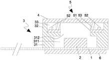
图1为本申请实施例提供的检测模组的剖视示意图;1 is a schematic cross-sectional view of a detection module provided by an embodiment of the present application;
图2为本申请实施例提供的检测模组的俯视图;2 is a top view of a detection module provided by an embodiment of the present application;
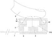
图3为本申请实施例提供的检测模组接收人体反射光线的原理示意图;3 is a schematic diagram of the principle of receiving reflected light from a human body by a detection module provided by an embodiment of the present application;
图4为本申请实施例提供的电子设备的外观结构图;FIG. 4 is an appearance structure diagram of an electronic device provided by an embodiment of the present application;
图5为本申请实施例提供的电子设备的剖视结构示意图。FIG. 5 is a schematic cross-sectional structural diagram of an electronic device provided by an embodiment of the present application.
图中:In the picture:
100-电子设备;100 - Electronic equipment;
1-电路板;1 - circuit board;
2-感光芯片;2 - photosensitive chip;
3-支架;3 - bracket;
31-底座部;31 - base part;
311-芯片腔;311 - chip cavity;
312-入光口;312 - light entrance;
32-环挡部;32 - ring stopper;
321-第一挡壁;321 - the first barrier;
322-第二挡壁;322 - the second retaining wall;
33-安装槽;33 - installation slot;
4-盖板;4 - cover plate;
5-检测光源;5 - detection light source;
51-光源电路板;51 - light source circuit board;
52-灯体;52 - lamp body;
53-遮光部;53 - shading part;
6-加强板;6- Reinforcing plate;
7-机壳;7-Case;
8-粘合胶;8 - adhesive glue;
9-手指。9 - Fingers.
具体实施方式Detailed ways
为使本公开的目的、技术方案和优点更加清楚,下面将结合本公开具体实施例及相应的附图对本公开技术方案进行清楚、完整地描述。显然,所描述的实施例仅是本公开一部分实施例,而不是全部的实施例。基于本公开中的实施例,本领域普通技术人员在没有做出创造性劳动前提下所获得的所有其他实施例,都属于本公开保护的范围。In order to make the purpose, technical solutions and advantages of the present disclosure clearer, the technical solutions of the present disclosure will be clearly and completely described below with reference to the specific embodiments of the present disclosure and the corresponding drawings. Obviously, the described embodiments are only some, but not all, embodiments of the present disclosure. Based on the embodiments in the present disclosure, all other embodiments obtained by those of ordinary skill in the art without creative efforts shall fall within the protection scope of the present disclosure.
本公开的说明书和权利要求书中的术语“第一”、“第二”等是用于区别类似的对象,而不用于描述特定的顺序或先后次序。应该理解这样使用的数据在适当情况下可以互换,以便本公开的实施例能够以除了在这里图示或描述的那些以外的顺序实施。此外,说明书以及权利要求中“和/或”表示所连接对象的至少其中之一,字符“/”,一般表示前后关联对象是一种“或”的关系。The terms "first", "second", etc. in the description and claims of the present disclosure are used to distinguish similar objects, and are not used to describe a specific order or sequence. It is to be understood that data so used may be interchanged under appropriate circumstances so that embodiments of the present disclosure can be practiced in sequences other than those illustrated or described herein. In addition, "and/or" in the description and claims indicates at least one of the connected objects, and the character "/" generally indicates that the associated objects are in an "or" relationship.
以下结合附图,详细说明本公开各个实施例公开的技术方案。The technical solutions disclosed by the various embodiments of the present disclosure will be described in detail below with reference to the accompanying drawings.
参见图1至图5所示,本申请提供一种电子设备100,该电子设备100便于用户随身携带,该电子设备100可以打电话、看视频、听音频、玩游戏等等,该电子设备100上集成了检测模组,从而使得该电子设备100还具有检测人体生理参数的功能,如检测人体的温度参数、血液参数等等。1 to 5, the present application provides an
需要注意的是,本申请实施例提供的电子设备具体可以为手机、平板电脑、收音机、游戏机、剃须刀等等,在此不做限定。It should be noted that the electronic device provided by the embodiment of the present application may specifically be a mobile phone, a tablet computer, a radio, a game console, a shaver, etc., which is not limited herein.
具体的,参见图1和图2所示,该检测模组设置于电子设备100的电路板1上,该检测模组包括感光芯片2、支架3、盖板4和检测光源5。感光芯片2设置于电路板1上,支架3设置电路板1上,所述支架3围设于所述感光芯片2周侧。所述支架3具有安装槽33。所述盖板4覆盖在所述支架3上且与所述感光芯片2相对,所述盖板4的透光度随着温度的改变而变化。检测光源5设置在所述安装槽33内,所述检测光源5发出的光线从所述盖板4的第一区域射出,经过反射后从所述盖板4的第二区域射入至所述感光芯片2表面。该感光芯片2在接收到反射的光线后,生成相应的光谱信号。示例性的,该感光芯片2可以为多光谱图像芯片。Specifically, as shown in FIG. 1 and FIG. 2 , the detection module is disposed on the
本申请实施例提供的检测模组结构简单,可在接收到反射光线时,生成相应的光谱数据。该检测模组在集成到电子设备100上时,电子设备可对光谱数据进行数据分析,得到人体多项生理参数信息,从而丰富了电子设备的功能,方便了用户及时有效的检测生理参数,知悉自身健康状况。The detection module provided by the embodiment of the present application has a simple structure, and can generate corresponding spectral data when receiving reflected light. When the detection module is integrated into the
参见图1至图3所示,在一种可能的实施方案中,支架3包括底座部31和环挡部32,所述底座部31形成有芯片腔311和连通所述芯片腔311的入光口312。所述环挡部32连接于所述底座部31,且环绕所述入光口312周向设置,所述安装槽33设置在所述底座部31上,所述盖板4设置于所述环挡部32上,覆盖所述安装槽33和所述入光口312。所述盖板的第一区域对应所述安装槽33,所述第二区域对应所述入光口312。Referring to FIG. 1 to FIG. 3 , in a possible embodiment, the
其中,盖板4可以包括主体部分(未图示)和环绕主体部分一周的支撑边(未图示),支撑边与主体部分之间形成有台阶面,支撑边支撑在环挡部32的顶部端面上,主体部分凸出于支撑边的部分插入在环挡部32围合形成的区域内,从而使得盖板4限位安装在环挡部32上。The
支架3上还可以设置连通芯片腔311的安装口,支架3具有该安装口的一侧盖设在电路板1上,感光芯片2由该安装口伸入芯片腔311内。该安装口的横截面面积大于入光口312的面积,从而方便支架3覆盖感光芯片2,且不会与感光芯片2产生干涉。该支架3的设计,除了起到覆盖感光芯片2,保护芯片的作用外,同时还作为主体结构,方便安装检测光源5和盖板4。A mounting opening communicating with the
其中,本申请实施例提供的盖板4包括透光玻璃和设置在透光玻璃上的热致变色涂层。热致变色涂层的颜色深度随温度的改变而改变。该盖板4具有两个功能,第一个功能是封堵芯片腔311的入光口312,保护内部的感光芯片2;第二个功能是充当检测光的传输介质。Wherein, the
在一种可能的实施方案中,所述检测光源5可以包括可见光源和/或红外光源。In a possible implementation, the
其中,当检测光源5包括可见光源时,检测模组和电子设备配合可以检测人体体温参数。盖板4上的热致变色涂层受温度影响颜色会发生变化,且一般是温度越高,热致变色涂层的颜色越浅,即温度与热致变色涂层的颜色变化是成线性比例变化的。具体的,参见图3所示,当人体肌肤如手指9、手腕、额头等部分接触到该盖板4时,会将人体体温传导到盖板4的热致变色涂层上。热致变色涂层的温度发生改变,则热致变色涂层的颜色深浅相应发生变化,从而使得盖板4的透光率发了改变。由检测光源5的灯体52发出检测光照射在人体肌肤后会有一部分光线反射,反射的光线透过了该盖板4后,被感光芯片2接收,感光芯片2生成相应的光谱信号。电子设备根据感光芯片2生成的光谱信号即可确定相应的体温参数。例如:电子设备内还设置有处理器,该处理器数据连接感光芯片2,该处理器根据感光芯片2生成的光谱信号中反射光的光强参数可匹配出对应的人体体温。Wherein, when the
以下提供一种可能的实施方案:电子设备还包括数据存储模块,数据存储模块内存储有体温与光强参数的对应关系。电子设备的处理器直接根据感光芯片2检测的反射光的光强参数,即可由所述对应关系中匹配出相应的体温参数。A possible implementation is provided below: the electronic device further includes a data storage module, where the corresponding relationship between body temperature and light intensity parameters is stored in the data storage module. The processor of the electronic device can directly match the corresponding body temperature parameter from the corresponding relationship according to the light intensity parameter of the reflected light detected by the
当本申请实施例提供的检测模组的检测光源5包括红外光源时,该电子设备还可以检测人体的血液参数信息。所述血液参数信息包括血氧参数、血糖参数、血脂参数中的至少一种。When the
具体的,人体血液是红色的,当检测光源5包括红外光源时,红外光源发出的红外光在照设在人体肌肤上时,会被血液反射,反射光线照设到感光芯片2上,感光芯片2接收到反射光线后,生成对应的光谱信号。电子设备可以根据该光谱信号分析出人体的血液参数信息。Specifically, human blood is red. When the
以下提供一种可能的实施方案,电子设备100的存储模块还存储有光谱曲线数据库。电子设备的处理器将感光芯片2生成的光谱信号处理成光谱曲线信息,并将光谱曲线信息与存储模块中的光谱曲线数据库进行比对,从而得到人体相应的血氧参数、血糖参数、血脂参数等血液参数。A possible implementation is provided below. The storage module of the
在一种可能的实施方案中,检测模组的检测光源5同时包括可见光源和红外光源。可见光源和红外光源可以同时点亮,多光谱信息在接收到反射光线后,生成可见光光谱信号和红外光光谱信号,所述处理器分析所述可见光光谱信号的光强度参数确定相应的体温信息。所述处理器根据所述红外光光谱信号生成相应的光谱曲线,根据所述光谱曲线分析相应的血液参数信息。该实施方案中,检测模组配合电子设备可同时检测人体的温度参数和血液参数,检测效率高,准确度高。In a possible implementation, the
参见图1和图2所示,在一种可能的实施方案中,所述支架3设置有安装槽33;所述安装槽33的出光口与所述芯片腔311的入光口312同侧设置。所述检测光源5设置于所述安装槽33内。Referring to FIGS. 1 and 2 , in a possible implementation, the
在该实施方案中,通过在支架3上设置安装槽33,使得检测光源5嵌入在安装槽33内,使得整体结构紧促,检测光源5不占据额外的空间,实现了紧促化设计。另外,安装槽33的出光口和芯片腔311的入光口312位于支架3的同侧,均朝向盖板4,如此则当人体肌肤接触到该盖板4时,检测光源5发射的检测光通过出光口照设到人体,由人体反射的检测光可照设到入光口312一侧,最终被感光芯片2接收。In this embodiment, the installation groove 33 is provided on the
其中,可以在支架3上环绕芯片腔311的入光口312周侧开设多个安装槽33,每个安装槽33内均设置检测光源5。或者,也可以在支架3上环绕芯片腔311的入光口312的一周设置一个环形的安装槽33,在安装槽33内间隔的设置若干检测光源5。Wherein, a plurality of installation grooves 33 may be formed on the
参见图1和图3所示,在一种可能的实施方案中,检测光源5包括两个可见光源,两个可见光源分设于所述入光口312的相对两侧,且两个可见光源和入光口312在同一条直线上。Referring to FIG. 1 and FIG. 3 , in a possible implementation, the
本实施方案中,通过设置两个可见光源增强了光线强度,利于提高检测准确度。另外本实施方案中两个可见光源以入光口312为中心设置于入光口312的相对两侧,则两个可见光源发射的检测光经过人体肌肤反射后形成的反射光线更加均匀,反射光线均匀的照设在感光芯片2上,从而使得感光芯片2能够转化成有效的光谱信号,提高温度参数的检测精度。In this embodiment, the light intensity is enhanced by arranging two visible light sources, which is beneficial to improve the detection accuracy. In addition, in this embodiment, the two visible light sources are arranged on opposite sides of the
在一种可能的实施方案中,检测光源5包括一个可见光源和一个红外光源,该可见光源和红外光源分设于入光口312的两侧。In a possible implementation, the
在一种可能的实施方案中,检测光源5包括两个红外光源,两个红外光源分设于所述入光口312的相对两侧,且两个红外光源和入光口312在同一条直线上。In a possible implementation, the
本实施方案中,通过设置两个红外光源增强了光信号强度,利于提高检测准确度。另外本实施方案中两个红外光源以入光口312为中心设置于入光口312的相对两侧,则两个红外光源发射的检测光经过人体反射后形成的反射光线更加均匀,反射光线均匀的照射在感光芯片2上,从而使得感光芯片2能够转化成有效的光谱信号,提高血液参数的检测精度。In this embodiment, the intensity of the light signal is enhanced by arranging two infrared light sources, which is beneficial to improve the detection accuracy. In addition, in this embodiment, the two infrared light sources are arranged on opposite sides of the
参见图1至图3所示,在一种可能的实施方案中,所述安装槽33包括第一安装槽和第二安装槽。所述支架包括底座部31和连接于所述底座部31的环挡部32。所述环挡部32包括第一挡壁321和第二挡壁322。所述第一安装槽设置于所述第一挡壁321内侧,所述第二安装槽设置于所述第二挡壁322内侧,所述可见光源设置于所述第一安装槽内,所述红外光源设置于所述第二安装槽内。Referring to FIG. 1 to FIG. 3 , in a possible embodiment, the installation groove 33 includes a first installation groove and a second installation groove. The bracket includes a
其中,所述环挡部32包括两个相对设置的第一挡壁321和两个相对设置的第二挡壁322,所述第一挡壁和所述第二挡壁322相连接。即可见光源和红外光源相邻设置,而不是相对设置,有效的防止了光线之间的干扰。The
该实施方案中,检测光源5同时包括两个可见光源和两个红外光源,每一检测光源5包括一个灯体52。两个所述可见光源分设于所述入光口312沿第一方向的相对两侧,两个所述红外光源分设于所述入光口312沿第二方向的相对两侧。其中,所述第一方向和所述第二方向相垂直,即两个可见光源分别设置于两个第一挡壁321内侧,两个红外光源分别设置于两个第二挡壁322内侧。该实施方案的结构设计更加规整合理。将入光口312设置为方形孔,环挡部32为环绕入光口312的方形,环挡部32对应方向孔的四个边分别设置有两第一挡壁321和两第二挡壁322,第一挡壁321内侧设置第一安装槽,第二挡壁322内侧设置第二安装槽,如此,在装配检测光源5的过程中,不需要调节各两可见光源和红外光源的安装位置,环挡部的四个挡壁内侧即为四个检测光源5的安装位置,从而利于检测光源5和支架3之间的快速装配。In this embodiment, the
参见图1至图3所示,在一种可能的实施方案中,电子设备还包括遮光部53,所述遮光部53设置于所述检测光源5和所述入光口312之间。所述遮光部53与所述环挡部32构成所述安装槽33。所述盖板4连接于所述支架3时,所述遮光部53与所述盖板4抵接。Referring to FIG. 1 to FIG. 3 , in a possible implementation, the electronic device further includes a
在该实施方案中,通过在检测光源5和入光口312之间设置遮光部53,防止检测光源5发射的检测光直接照设到入光口312,影响到电子设备的检测信号的准确度。另外通过遮光部53设置,可以在盖板4连接于所述支架3时,该遮光部53支撑于盖板4底部,提高盖板4的安装稳定性。In this embodiment, by disposing the
其中,该盖板4包括透光玻璃,透光玻璃在位于遮光部53所环绕的区域内的部分可以涂覆热致变色涂层,而在遮光部53所环绕的区域之外的部分则可以不设置热致变色涂层,该部分结构为全透明结构,如此则检测光源5发出检测光线透过该全透明结构部分,检测光线没有衰减,从而提高了检测光强度。The
优选地,所述检测光源5包括光源电路板51和连接于所述光源电路板51的灯体52。所述光源电路板51沿所述入光口312的周向设置,所述灯体52设置于所述遮光部53与所述环挡部32构成的安装槽33内,所述遮光部53将所述灯体52和所述入光口312隔开。Preferably, the
在该实施方案中,遮光部53可以直接设置在光源电路板51上,在实际装配过程中,只需要装配好光源电路板51即可,用户不需要专门再装配遮光部53,从而简化了装配过程,提高了生产效率。其中,为了便于安装检测光源5,该光源电路板51可以为柔性电路板。In this embodiment, the
另外,在另一种可能的实施方案中,该遮光部53也可以不设置在光源电路板51上,而是设置在安装槽33上。再或者,该遮光部53可以为支架3上环绕入光口312一周凸出设置的凸筋结构。In addition, in another possible implementation, the
其中,遮光部53可以为遮光泡棉或遮光胶套。The light-shielding
参见图1至图3所示,在一种可能的实施方案中,电子设备包括处理器,所述电路板1为柔性电路板。柔性电路板连接于所述处理器。为了便于将感光芯片2和支架3安装在电路板上,提高支架3与电路板的转配结构强度,防止支架3脱离电路板,本申请实施例中在所述电路板1背离所述支架3的一侧连接加强板6。加强板6的设置,增加了柔性电路板的局部硬度,减小了柔性电路板局部的形变量,方便了安装感光芯片2和支架3。Referring to FIG. 1 to FIG. 3 , in a possible embodiment, the electronic device includes a processor, and the
具体的,参见图4和图5所示,所述电子设备包括机壳7,所述机壳7具有安装槽,安装槽具有一定纵向延伸长度,支架3嵌入安装于所述安装槽内,且所述盖板4露出。从而方便与人体肌肤接触。电子设备的壳体具有空腔,电路板1位于空腔内,电路板1环绕支架3一周的部分通过粘合胶8粘接在壳体内壁上。Specifically, as shown in FIG. 4 and FIG. 5 , the electronic device includes a
其中,机壳7包括前面板、中框和后盖,可以在前面板、中框的侧部或者后盖上设置所述安装槽,在此不做限定。The
在人体肌肤不接触盖板4时,盖板4与机壳7的颜色接近,电子设备具有一体的整机视觉效果。而在人体肌肤接触该盖板4时,盖板4颜色会变浅或者完全透明。When the human skin does not contact the
上面结合附图对本公开的实施例进行了描述,但是本公开并不局限于上述的具体实施方式,上述的具体实施方式仅仅是示意性的,而不是限制性的,本领域的普通技术人员在本公开的启示下,在不脱离本公开宗旨和权利要求所保护的范围情况下,还可做出很多形式,均属于本公开的保护之内。The embodiments of the present disclosure have been described above in conjunction with the accompanying drawings, but the present disclosure is not limited to the above-mentioned specific embodiments, which are merely illustrative rather than restrictive. Under the inspiration of the present disclosure, without departing from the scope of the present disclosure and the protection scope of the claims, many forms can be made, which all fall within the protection of the present disclosure.
Claims (8)
Translated fromChinesePriority Applications (1)
| Application Number | Priority Date | Filing Date | Title |
|---|---|---|---|
| CN202010805960.0ACN112040052B (en) | 2020-08-12 | 2020-08-12 | Detection module and electronic equipment |
Applications Claiming Priority (1)
| Application Number | Priority Date | Filing Date | Title |
|---|---|---|---|
| CN202010805960.0ACN112040052B (en) | 2020-08-12 | 2020-08-12 | Detection module and electronic equipment |
Publications (2)
| Publication Number | Publication Date |
|---|---|
| CN112040052A CN112040052A (en) | 2020-12-04 |
| CN112040052Btrue CN112040052B (en) | 2022-05-17 |
Family
ID=73578630
Family Applications (1)
| Application Number | Title | Priority Date | Filing Date |
|---|---|---|---|
| CN202010805960.0AActiveCN112040052B (en) | 2020-08-12 | 2020-08-12 | Detection module and electronic equipment |
Country Status (1)
| Country | Link |
|---|---|
| CN (1) | CN112040052B (en) |
Families Citing this family (3)
| Publication number | Priority date | Publication date | Assignee | Title |
|---|---|---|---|---|
| CN113008378A (en)* | 2021-02-24 | 2021-06-22 | 维沃移动通信有限公司 | Terminal device |
| CN113079230B (en)* | 2021-03-18 | 2023-07-14 | Oppo广东移动通信有限公司 | Electronic equipment |
| CN114035022B (en)* | 2021-10-21 | 2024-12-03 | 武汉光谷信息光电子创新中心有限公司 | A chip testing tool and testing system |
Citations (8)
| Publication number | Priority date | Publication date | Assignee | Title |
|---|---|---|---|---|
| WO2014113681A1 (en)* | 2013-01-17 | 2014-07-24 | Eclipse Breast Health Technologies | Systems and methods for noninvasive health monitoring |
| CN105796114A (en)* | 2016-04-25 | 2016-07-27 | 深圳信炜科技有限公司 | Packaging structure of biosensor and electronic equipment |
| CN107928646A (en)* | 2017-11-08 | 2018-04-20 | 聚动(厦门)科技有限公司 | Optical module and photoelectric detection system |
| WO2019035133A1 (en)* | 2017-08-17 | 2019-02-21 | Wear2B Ltd. | Device, system and method for non-invasive monitoring of physiological measurements |
| CN109670478A (en)* | 2018-12-29 | 2019-04-23 | 联想(北京)有限公司 | Electronic equipment and its control method |
| CN110376780A (en)* | 2019-07-20 | 2019-10-25 | 深圳阜时科技有限公司 | Shield lower detection system, liquid crystal display device and backlight module |
| CN210401950U (en)* | 2019-07-20 | 2020-04-24 | 深圳阜时科技有限公司 | Detection system, liquid crystal display device and backlight module under screen |
| CN111522166A (en)* | 2019-02-01 | 2020-08-11 | 松下知识产权经营株式会社 | Display device |
Family Cites Families (9)
| Publication number | Priority date | Publication date | Assignee | Title |
|---|---|---|---|---|
| GB8318863D0 (en)* | 1983-07-12 | 1983-08-10 | Secr Defence | Thermochromic liquid crystal displays |
| KR101544793B1 (en)* | 2008-12-04 | 2015-08-18 | 삼성디스플레이 주식회사 | Shielding member having variable transparency, display plate including the same, and manufacturing method thereof |
| JP4748266B2 (en)* | 2009-01-30 | 2011-08-17 | ソニー株式会社 | Information input device, information input / output device, and electronic device |
| KR20250021617A (en)* | 2014-09-02 | 2025-02-13 | 애플 인크. | Wearable electronic device |
| WO2016150749A1 (en)* | 2015-03-23 | 2016-09-29 | Koninklijke Philips N.V. | Optical vital signs sensor |
| JP6679377B2 (en)* | 2016-03-30 | 2020-04-15 | 日東電工株式会社 | Temperature sensor |
| CN207886208U (en)* | 2017-05-19 | 2018-09-21 | 国家电网公司 | A kind of embedded human physiologic information non-invasive detection system |
| WO2020105757A1 (en)* | 2018-11-23 | 2020-05-28 | 엘지전자 주식회사 | Mobile terminal |
| CN208819534U (en)* | 2019-03-28 | 2019-05-03 | 北京小米移动软件有限公司 | a terminal |
- 2020
- 2020-08-12CNCN202010805960.0Apatent/CN112040052B/enactiveActive
Patent Citations (8)
| Publication number | Priority date | Publication date | Assignee | Title |
|---|---|---|---|---|
| WO2014113681A1 (en)* | 2013-01-17 | 2014-07-24 | Eclipse Breast Health Technologies | Systems and methods for noninvasive health monitoring |
| CN105796114A (en)* | 2016-04-25 | 2016-07-27 | 深圳信炜科技有限公司 | Packaging structure of biosensor and electronic equipment |
| WO2019035133A1 (en)* | 2017-08-17 | 2019-02-21 | Wear2B Ltd. | Device, system and method for non-invasive monitoring of physiological measurements |
| CN107928646A (en)* | 2017-11-08 | 2018-04-20 | 聚动(厦门)科技有限公司 | Optical module and photoelectric detection system |
| CN109670478A (en)* | 2018-12-29 | 2019-04-23 | 联想(北京)有限公司 | Electronic equipment and its control method |
| CN111522166A (en)* | 2019-02-01 | 2020-08-11 | 松下知识产权经营株式会社 | Display device |
| CN110376780A (en)* | 2019-07-20 | 2019-10-25 | 深圳阜时科技有限公司 | Shield lower detection system, liquid crystal display device and backlight module |
| CN210401950U (en)* | 2019-07-20 | 2020-04-24 | 深圳阜时科技有限公司 | Detection system, liquid crystal display device and backlight module under screen |
Also Published As
| Publication number | Publication date |
|---|---|
| CN112040052A (en) | 2020-12-04 |
Similar Documents
| Publication | Publication Date | Title |
|---|---|---|
| CN112040052B (en) | Detection module and electronic equipment | |
| US11504057B2 (en) | Optical sensor subsystem adjacent a cover of an electronic device housing | |
| US10698514B2 (en) | Sensor assembly and terminal | |
| US12020603B2 (en) | Electronic devices having image transport layers and electrical components | |
| EP3773176B1 (en) | Sensor including first optical member with reflection property and second optical member with absorption property capable of absorbing light reflected by first optical member and electronic device including the same | |
| CN216700554U (en) | Shell assembly, wearable equipment and electronic equipment | |
| CN109154961A (en) | Optics fingerprint sensing in LCD screen based on the optical imagery for utilizing lens-pinhole module and other optical designs | |
| CN212118134U (en) | Wearable device | |
| CN216495266U (en) | Detection device and electronic equipment of biological characteristic information | |
| CN105072998A (en) | Palm vein image capture device | |
| CN109363628B (en) | Shell, health monitoring device and wearable equipment | |
| WO2023060975A1 (en) | Stent having fresnel combination lens, circuit board, and electronic device | |
| WO2017181385A1 (en) | Hand-held electronic apparatus | |
| KR20210062974A (en) | Electronic device and method for measuring vital signals | |
| KR102732895B1 (en) | Biometric sensor module and electronic device including the same | |
| CN109363656B (en) | Health monitoring device and wearable equipment | |
| CN212134988U (en) | Light guides and screens | |
| CN218074996U (en) | Terminal device | |
| CN214804653U (en) | Health detection structure and wearable device | |
| CN108183984B (en) | I/O modules and electronic devices | |
| CN111953824B (en) | electronic device | |
| CN218352694U (en) | Earphone set | |
| CN209283278U (en) | Terminal Equipment | |
| CN108156285B (en) | electronic device | |
| CN221175022U (en) | Sensor module with backlight |
Legal Events
| Date | Code | Title | Description |
|---|---|---|---|
| PB01 | Publication | ||
| PB01 | Publication | ||
| SE01 | Entry into force of request for substantive examination | ||
| SE01 | Entry into force of request for substantive examination | ||
| GR01 | Patent grant | ||
| GR01 | Patent grant |