CN112034591A - Optical systems, camera modules and electronics - Google Patents
Optical systems, camera modules and electronicsDownload PDFInfo
- Publication number
- CN112034591A CN112034591ACN202010976667.0ACN202010976667ACN112034591ACN 112034591 ACN112034591 ACN 112034591ACN 202010976667 ACN202010976667 ACN 202010976667ACN 112034591 ACN112034591 ACN 112034591A
- Authority
- CN
- China
- Prior art keywords
- lens
- optical system
- optical axis
- convex
- image
- Prior art date
- Legal status (The legal status is an assumption and is not a legal conclusion. Google has not performed a legal analysis and makes no representation as to the accuracy of the status listed.)
- Granted
Links
Images


Classifications
- G—PHYSICS
- G02—OPTICS
- G02B—OPTICAL ELEMENTS, SYSTEMS OR APPARATUS
- G02B13/00—Optical objectives specially designed for the purposes specified below
- G02B13/001—Miniaturised objectives for electronic devices, e.g. portable telephones, webcams, PDAs, small digital cameras
- G02B13/0015—Miniaturised objectives for electronic devices, e.g. portable telephones, webcams, PDAs, small digital cameras characterised by the lens design
- G02B13/002—Miniaturised objectives for electronic devices, e.g. portable telephones, webcams, PDAs, small digital cameras characterised by the lens design having at least one aspherical surface
- G02B13/0045—Miniaturised objectives for electronic devices, e.g. portable telephones, webcams, PDAs, small digital cameras characterised by the lens design having at least one aspherical surface having five or more lenses
- G—PHYSICS
- G02—OPTICS
- G02B—OPTICAL ELEMENTS, SYSTEMS OR APPARATUS
- G02B13/00—Optical objectives specially designed for the purposes specified below
- G02B13/001—Miniaturised objectives for electronic devices, e.g. portable telephones, webcams, PDAs, small digital cameras
- G02B13/0055—Miniaturised objectives for electronic devices, e.g. portable telephones, webcams, PDAs, small digital cameras employing a special optical element
- G02B13/0065—Miniaturised objectives for electronic devices, e.g. portable telephones, webcams, PDAs, small digital cameras employing a special optical element having a beam-folding prism or mirror
- G—PHYSICS
- G02—OPTICS
- G02B—OPTICAL ELEMENTS, SYSTEMS OR APPARATUS
- G02B13/00—Optical objectives specially designed for the purposes specified below
- G02B13/18—Optical objectives specially designed for the purposes specified below with lenses having one or more non-spherical faces, e.g. for reducing geometrical aberration
Landscapes
- Physics & Mathematics (AREA)
- General Physics & Mathematics (AREA)
- Optics & Photonics (AREA)
- Lenses (AREA)
Abstract
Translated fromChinese
Description
Translated fromChinese技术领域technical field
本发明属于光学成像技术领域,尤其涉及一种光学系统、摄像头模组和电子设备。The invention belongs to the technical field of optical imaging, and in particular relates to an optical system, a camera module and an electronic device.
背景技术Background technique
智能手机、平板等电子产品制造技术不断发展,而作为图像数据采集重要基础部分之一的镜头,也在进行着多样化的发展,随着市场对摄像高成像品质的要求,镜头需具有较好的摄远效果,然而传统的长焦镜头的长度较长,难以满足小型化的要求。The manufacturing technology of electronic products such as smart phones and tablets is constantly developing, and the lens, which is one of the important basic parts of image data acquisition, is also undergoing diversified development. However, the length of the traditional telephoto lens is long, and it is difficult to meet the requirements of miniaturization.
因此,潜望式镜头应运而生,而如何使得潜望式镜头在具有较好的摄远效果的同时,满足小型化的要求是急需解决的技术问题。Therefore, the periscope lens emerges as the times require, and how to make the periscope lens have a good telephoto effect while meeting the requirements of miniaturization is a technical problem that needs to be solved urgently.
发明内容SUMMARY OF THE INVENTION
本申请的目的在于提供一种光学系统、摄像头模组和电子设备,用于解决上述技术问题。The purpose of the present application is to provide an optical system, a camera module and an electronic device for solving the above technical problems.
为实现本申请的目的,本申请提供了如下的技术方案:To achieve the purpose of the application, the application provides the following technical solutions:
第一方面,本申请提供了一种光学系统,沿第一光轴方向的物侧至像侧依次包含:第一透镜,具有正屈折力,所述第一透镜物侧面近轴处为凸面,所述第一透镜像侧面近轴处为平面;棱镜,用于折转光路,使光路由所述第一光轴转向到第二光轴上,所述第一光轴与所述第二光轴相交;沿所述第二光轴方向的物侧至像侧依次包含:第二透镜,具有正屈折力,所述第二透镜物侧面近轴处为凸面,所述第二透镜像侧面近轴处为凸面;第三透镜,具有屈折力,所述第三透镜物侧面近轴处为凹面;第四透镜,具有屈折力;第五透镜,具有屈折力;第六透镜,具有负屈折力,所述第六透镜物侧面近轴处为凸面,所述第六透镜像侧面近轴处为凹面;第七透镜,具有负屈折力。通过合理配置所述第一透镜至所述第七透镜的各透镜的面型和屈折力,使得本申请所述的光学系统能够在满足较好的摄远效果的同时,实现结构小型化。In a first aspect, the present application provides an optical system, comprising in sequence from the object side to the image side along the first optical axis: a first lens having a positive refractive power, the object side of the first lens being a convex surface at the paraxial position, The paraxial position of the image side of the first lens is a plane; the prism is used to refract the optical path, so that the optical path is turned from the first optical axis to the second optical axis, and the first optical axis is connected with the second optical axis. The axes intersect; the object side to the image side in the direction of the second optical axis sequentially includes: a second lens with positive refractive power, the object side of the second lens is convex at the paraxial position, and the image side of the second lens is close to the image side. The axis is convex; the third lens has refractive power, and the paraxial position of the object side of the third lens is concave; the fourth lens has refractive power; the fifth lens has refractive power; the sixth lens has negative refractive power , the object side of the sixth lens is convex at the paraxial position, the image side of the sixth lens is concave at the paraxial position; the seventh lens has a negative refractive power. By rationally configuring the surface shapes and refractive powers of the first lens to the seventh lens, the optical system described in the present application can achieve a compact structure while satisfying a better telephoto effect.
一种实施方式中,所述第一透镜至所述第七透镜中至少一个透镜的至少一个表面为非球面。在此结构下,所述光学系统能够在满足较好的摄远效果的同时,实现结构小型化。In one embodiment, at least one surface of at least one lens among the first lens to the seventh lens is aspherical. Under this structure, the optical system can achieve a miniaturized structure while satisfying a better telephoto effect.
一种实施方式中,所述光学系统满足条件式:1.6<TTL/(ImgH*2)<2.5;11°<HFOV<16°;0.6<DL/TTL<0.8;其中,TTL为所述第二透镜的物侧面至所述光学系统的成像面于所述第二光轴上的距离,ImgH为所述光学系统于成像面上有效成像区域对角线长度的一半,HFOV为所述光学系统最大视场角的一半,DL为所述第二透镜物侧面与所述第七透镜像侧面于所述第二光轴上的距离。当所述光学系统满足上述条件式时,即对所述第二透镜至所述第七透镜进行合理的结构布局,使镜头高度与成像面比值在一个较小范围,从而使所述光学系统实现小型化,并在实现小型化的基础上,减小镜片部分的空间,有利于模组结构端的布局。In one embodiment, the optical system satisfies the conditional formula: 1.6<TTL/(ImgH*2)<2.5; 11°<HFOV<16°; 0.6<DL/TTL<0.8; wherein, TTL is the second The distance from the object side of the lens to the imaging plane of the optical system on the second optical axis, ImgH is half of the diagonal length of the effective imaging area of the optical system on the imaging plane, HFOV is the maximum length of the optical system Half of the field of view, DL is the distance between the object side surface of the second lens and the image side surface of the seventh lens on the second optical axis. When the optical system satisfies the above-mentioned conditional expression, the second lens to the seventh lens are arranged in a reasonable structure, so that the ratio of the height of the lens to the imaging surface is within a small range, so that the optical system can achieve Miniaturization, and on the basis of realizing miniaturization, the space of the lens part is reduced, which is beneficial to the layout of the structural end of the module.
一种实施方式中,所述光学系统满足条件式:0.9<TTL/f<1.2;其中,TTL为所述第二透镜的物侧面至所述光学系统的成像面于所述第二光轴上的距离,f为所述光学系统的有效焦距。当所述光学系统满足上述条件式时,在HFOV<16°范围内可提供更低的镜头高度,使得所述光学系统更加容易植入便携式设备中。同时,非球面的使用,使得TTL与f的比值处于一个较小的数值范围内,在实现摄远摄影条件下,利于所述光学系统平衡色差、球差等像差,获得良好的成像品质。In an embodiment, the optical system satisfies the conditional formula: 0.9<TTL/f<1.2; wherein, TTL is on the second optical axis from the object side of the second lens to the imaging plane of the optical system , and f is the effective focal length of the optical system. When the optical system satisfies the above-mentioned conditional formula, a lower lens height can be provided in the range of HFOV<16°, so that the optical system can be more easily implanted in a portable device. At the same time, the use of the aspheric surface makes the ratio of TTL to f within a small numerical range, which is beneficial for the optical system to balance aberrations such as chromatic aberration and spherical aberration, and obtain good imaging quality under the condition of realizing telephoto photography.
一种实施方式中,所述光学系统满足条件式:EFY(L2~L7)>10mm;其中,EFY(L2~L7)为所述第二透镜至所述第七透镜组成的后透镜组的焦距。当所述光学系统满足上述条件式时,即通过合理配置所述第一透镜与所述后透镜组的光焦度,通过所述第一透镜进入的光线,再通过所述后透镜组有效的平衡、校正产生的像差及边缘光线的有效汇聚,可以在保证所述光学系统的紧凑化、小型化的同时,使所述光学系统具备较好的摄远效果。In an embodiment, the optical system satisfies the conditional formula: EFY(L2-L7)>10mm; wherein, EFY(L2-L7) is the focal length of the rear lens group composed of the second lens to the seventh lens . When the optical system satisfies the above conditional expression, that is, by reasonably configuring the optical power of the first lens and the rear lens group, the light entering through the first lens, and then passing through the rear lens group effectively The aberrations generated by balancing and correction and the effective convergence of marginal light rays can ensure the compactness and miniaturization of the optical system, and at the same time make the optical system have a better telephoto effect.
一种实施方式中,所述光学系统满足条件式:T56/T67<0.25;其中,T56为所述第五透镜的像侧面与所述第六透镜的物侧面于所述第二光轴上的间隔距离,T67为所述第六透镜的像侧面与所述第七透镜的物侧面于所述第二光轴上的间隔距离。当所述光学系统满足上述条件式时,即通过合理配置所述第五透镜和所述第六透镜之间,以及所述第六透镜和所述第七透镜之间的位置关系,能够有效压缩所述光学系统的长度尺寸,减缓光线进入所述光学系统后的方向变化,有助于降低杂散光的强度。In an embodiment, the optical system satisfies the conditional formula: T56/T67<0.25; wherein, T56 is the difference between the image side of the fifth lens and the object side of the sixth lens on the second optical axis. The separation distance, T67 is the separation distance between the image side of the sixth lens and the object side of the seventh lens on the second optical axis. When the optical system satisfies the above-mentioned conditional expression, that is, by reasonably configuring the positional relationship between the fifth lens and the sixth lens, and between the sixth lens and the seventh lens, it can effectively compress The length dimension of the optical system slows down the direction change of light after entering the optical system, which helps to reduce the intensity of stray light.
一种实施方式中,所述光学系统满足条件式:|f2/f1|<0.3;其中,f1为所述第一透镜的有效焦距,f2为所述第二透镜的有效焦距。当所述光学系统满足上述条件式时,即通过合理配置所述第一透镜和所述第二透镜的尺寸与屈折力,可平衡前透镜组产生的较大球差,提升所述光学系统整体的解像力,并控制所述光学系统后端曲折力配置,强化所述光学系统周边像差校正,同时,还有利于尺寸压缩,使所述光学系统实现小型化。In an embodiment, the optical system satisfies the conditional formula: |f2/f1|<0.3; wherein, f1 is the effective focal length of the first lens, and f2 is the effective focal length of the second lens. When the optical system satisfies the above conditional expression, that is, by reasonably configuring the size and refractive power of the first lens and the second lens, the large spherical aberration generated by the front lens group can be balanced, and the overall optical system can be improved. and control the configuration of the bending force at the rear end of the optical system to strengthen the correction of peripheral aberrations of the optical system, and at the same time, it is also conducive to size compression, so that the optical system can be miniaturized.
一种实施方式中,所述光学系统满足条件式:|V2-V4|>30;其中,V2为所述第二透镜阿贝数,V4为所述第四透镜阿贝数。当所述光学系统满足上述条件式时,即合理配置所述第二透镜和所述第四透镜的阿贝数,有利于所述光学系统的色差修正及性能保证。In an embodiment, the optical system satisfies the conditional formula: |V2-V4|>30; wherein, V2 is the Abbe number of the second lens, and V4 is the Abbe number of the fourth lens. When the optical system satisfies the above conditional expression, the Abbe numbers of the second lens and the fourth lens are reasonably configured, which is beneficial to the correction of chromatic aberration and the performance assurance of the optical system.
第二方面,本申请还提供了一种摄像头模组,包括镜筒、电子感光元件和第一方面任一实施方式中的光学系统,所述光学系统的所述第一透镜至所述第七透镜及所述棱镜安装在所述镜筒内,所述电子感光元件设置在所述光学系统的像侧,用于将穿过所述第一透镜、所述棱镜及所述第二透镜至所述第七透镜入射到所述电子感光元件上的物的光信号转换成图像的电信号。通过在所述摄像头模组中安装上述光学系统,能使所述摄像头模组能够在满足较好的摄远效果的同时,实现结构小型化。In a second aspect, the present application further provides a camera module, including a lens barrel, an electronic photosensitive element, and the optical system in any embodiment of the first aspect, wherein the first lens to the seventh lens of the optical system The lens and the prism are installed in the lens barrel, the electronic photosensitive element is arranged on the image side of the optical system, and is used to pass through the first lens, the prism and the second lens to the The seventh lens converts the optical signal of the object incident on the electronic photosensitive element into the electrical signal of the image. By installing the above-mentioned optical system in the camera module, the camera module can achieve a miniaturized structure while satisfying a better telephoto effect.
第三方面,本申请还提供了一种电子设备,包括壳体和第二方面所述的摄像头模组,所述摄像头模组设于所述壳体内。通过在电子设备中设置第二方面的摄像头模组,能使所述电子设备在满足较好的摄远效果的同时,实现结构小型化。In a third aspect, the present application further provides an electronic device, comprising a casing and the camera module described in the second aspect, wherein the camera module is arranged in the casing. By arranging the camera module of the second aspect in the electronic device, the electronic device can achieve a miniaturized structure while satisfying a better telephoto effect.
附图说明Description of drawings
为了更清楚地说明本发明实施例或现有技术中的技术方案,下面将对实施例或现有技术描述中所需要使用的附图作简单地介绍,显而易见地,下面描述中的附图仅仅是本发明的一些实施例,对于本领域普通技术人员来讲,在不付出创造性劳动的前提下,还可以根据这些附图获得其他的附图。In order to explain the embodiments of the present invention or the technical solutions in the prior art more clearly, the following briefly introduces the accompanying drawings that need to be used in the description of the embodiments or the prior art. Obviously, the accompanying drawings in the following description are only These are some embodiments of the present invention. For those of ordinary skill in the art, other drawings can also be obtained according to these drawings without creative efforts.
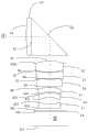
图1a是第一实施例的光学系统的结构示意图;1a is a schematic structural diagram of an optical system of the first embodiment;
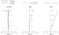
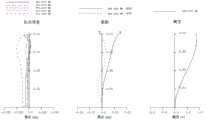
图1b是第一实施例的纵向球差曲线、像散曲线和畸变曲线;Fig. 1b is the longitudinal spherical aberration curve, astigmatism curve and distortion curve of the first embodiment;
图2a是第二实施例的光学系统的结构示意图;2a is a schematic structural diagram of an optical system of a second embodiment;
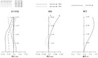
图2b是第二实施例的纵向球差曲线、像散曲线和畸变曲线;Fig. 2b is the longitudinal spherical aberration curve, astigmatism curve and distortion curve of the second embodiment;
图3a是第三实施例的光学系统的结构示意图;3a is a schematic structural diagram of an optical system of a third embodiment;
图3b是第三实施例的纵向球差曲线、像散曲线和畸变曲线;Fig. 3b is the longitudinal spherical aberration curve, astigmatism curve and distortion curve of the third embodiment;
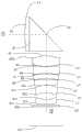
图4a是第四实施例的光学系统的结构示意图;4a is a schematic structural diagram of an optical system of a fourth embodiment;
图4b是第四实施例的纵向球差曲线、像散曲线和畸变曲线;Fig. 4b is the longitudinal spherical aberration curve, astigmatism curve and distortion curve of the fourth embodiment;
图5a是第五实施例的光学系统的结构示意图;Fig. 5a is the structural schematic diagram of the optical system of the fifth embodiment;
图5b是第五实施例的纵向球差曲线、像散曲线和畸变曲线;Fig. 5b is the longitudinal spherical aberration curve, astigmatism curve and distortion curve of the fifth embodiment;
图6a是第六实施例的光学系统的结构示意图;6a is a schematic structural diagram of an optical system according to a sixth embodiment;
图6b是第六实施例的纵向球差曲线、像散曲线和畸变曲线。FIG. 6b is a longitudinal spherical aberration curve, astigmatism curve and distortion curve of the sixth embodiment.
图7a是第七实施例的光学系统的结构示意图;7a is a schematic structural diagram of an optical system according to a seventh embodiment;
图7b是第七实施例的纵向球差曲线、像散曲线和畸变曲线;Fig. 7b is the longitudinal spherical aberration curve, astigmatism curve and distortion curve of the seventh embodiment;
具体实施方式Detailed ways
下面将结合本发明实施例中的附图,对本发明实施例中的技术方案进行清楚、完整地描述,显然,所描述的实施例仅仅是本发明一部分实施例,而不是全部的实施例。基于本发明中的实施例,本领域普通技术人员在没有作出创造性劳动前提下所获得的所有其他实施例,都属于本发明保护的范围。The technical solutions in the embodiments of the present invention will be clearly and completely described below with reference to the accompanying drawings in the embodiments of the present invention. Obviously, the described embodiments are only a part of the embodiments of the present invention, rather than all the embodiments. Based on the embodiments of the present invention, all other embodiments obtained by those of ordinary skill in the art without creative efforts shall fall within the protection scope of the present invention.
本申请实施例提供了一种摄像头模组,该摄像头模组包括镜筒、电子感光元件和本发明实施例提供的光学系统,光学系统的第一透镜至第七透镜及棱镜安装在镜筒内,电子感光元件设置在光学系统的像侧,用于将穿过第一透镜、棱镜及第二透镜至第七透镜入射到电子感光元件上的物的光信号转换成图像的电信号。电子感光元件可以为互补金属氧化物半导体(Complementary Metal Oxide Semiconductor,CMOS)或电荷耦合器件(Charge-coupled Device,CCD)。该摄像头模组可以是数码相机的独立的镜头,也可以是集成在如智能手机等电子设备上的成像模块。通过在摄像头模组内安装该光学系统的第一透镜至第七透镜及棱镜,合理配置第一透镜至第七透镜的各透镜的面型和屈折力,使得本申请实施例提供的摄像头模组能够在满足较好的摄远效果的同时,实现结构小型化。An embodiment of the present application provides a camera module. The camera module includes a lens barrel, an electronic photosensitive element, and the optical system provided by the embodiment of the present invention. The first lens to the seventh lens and the prism of the optical system are installed in the lens barrel. , the electronic photosensitive element is arranged on the image side of the optical system, and is used to convert the optical signal of the object incident on the electronic photosensitive element through the first lens, the prism and the second lens to the seventh lens into the electrical signal of the image. The electronic photosensitive element may be a complementary metal oxide semiconductor (Complementary Metal Oxide Semiconductor, CMOS) or a charge-coupled device (Charge-coupled Device, CCD). The camera module can be an independent lens of a digital camera, or an imaging module integrated on an electronic device such as a smart phone. By installing the first lens to the seventh lens and the prism of the optical system in the camera module, and reasonably configuring the surface shape and refractive power of each lens of the first lens to the seventh lens, the camera module provided by the embodiment of the present application can be achieved. The miniaturization of the structure can be achieved while satisfying the better telephoto effect.
本申请实施例提供了一种电子设备,该电子设备包括壳体和本申请实施例提供的摄像头模组。摄像头模组和电子感光元件设置在壳体内。该电子设备可以为智能手机、个人数字助理(PDA)、平板电脑、智能手表、无人机、电子书籍阅读器、行车记录仪、可穿戴装置等。通过在电子设备中设置本申请实施例提供的摄像头模组,使电子设备能够在满足较好的摄远效果的同时,实现结构小型化。The embodiments of the present application provide an electronic device, and the electronic device includes a casing and the camera module provided by the embodiments of the present application. The camera module and the electronic photosensitive element are arranged in the casing. The electronic device may be a smart phone, a personal digital assistant (PDA), a tablet computer, a smart watch, a drone, an electronic book reader, a driving recorder, a wearable device, and the like. By arranging the camera module provided by the embodiments of the present application in the electronic device, the electronic device can achieve a miniaturized structure while satisfying a better telephoto effect.
本申请实施例提供了一种光学系统,该光学系统沿第一光轴方向的物侧至像侧依次包含第一透镜和棱镜,棱镜用于折转光路,使光路有第一光轴①转向到第二光轴上②,第一光轴①与第二光轴②相交,该光学系统眼第二光轴②方向的物侧至像侧依次包含第二透镜、第三透镜、第四透镜、第五透镜、第六透镜和第七透镜。在第一透镜至第七透镜中,任意相邻两片透镜之间均可具有空气间隔。The embodiment of the present application provides an optical system, the optical system includes a first lens and a prism in sequence from the object side to the image side in the direction of the first optical axis, and the prism is used to fold the optical path, so that the optical path has the first
具体的,七片透镜的具体形状和结构如下:Specifically, the specific shapes and structures of the seven lenses are as follows:
第一透镜,具有正屈折力,第一透镜物侧面近轴处为凸面,第一透镜像侧面近轴处为平面;第二透镜,具有正屈折力,第二透镜物侧面近轴处为凸面,第二透镜像侧面近轴处为凸面;第三透镜,具有屈折力,第三透镜物侧面近轴处为凹面;第四透镜,具有屈折力;第五透镜,具有屈折力;第六透镜,具有负屈折力,第六透镜物侧面近轴处为凸面,第六透镜像侧面近轴处为凹面;第七透镜,具有负屈折力。通过合理配置第一透镜至第七透镜的各透镜的面型和屈折力,使得本申请的光学系统能够在满足较好的摄远效果的同时,实现结构小型化。The first lens has positive refractive power, and the paraxial position of the object side of the first lens is convex, and the paraxial position of the image side of the first lens is a plane; the second lens has positive refractive power, and the paraxial position of the second lens object side is convex. , the image side of the second lens is convex at the paraxial position; the third lens has refractive power, and the paraxial position of the object side of the third lens is concave; the fourth lens has refractive power; the fifth lens has refractive power; the sixth lens , has a negative refractive power, the sixth lens has a convex surface on the paraxial side of the object side, and the sixth lens has a concave surface on the paraxial side of the image side; the seventh lens has a negative refractive power. By rationally configuring the surface shapes and refractive powers of the lenses of the first to seventh lenses, the optical system of the present application can achieve a miniaturized structure while satisfying a better telephoto effect.
一种实施方式中,第一透镜至第七透镜中至少一个透镜的至少一个表面为非球面。在此结构下,光学系统能够在满足较好的摄远效果的同时,实现结构小型化。In one embodiment, at least one surface of at least one of the first to seventh lenses is aspherical. With this structure, the optical system can achieve a miniaturized structure while satisfying a better telephoto effect.
一种实施方式中,光学系统满足条件式:1.6<TTL/(ImgH*2)<2.5;11°<HFOV<16°;0.6<DL/TTL<0.8;其中,TTL为第二透镜的物侧面至光学系统的成像面于第二光轴②上的距离,ImgH为光学系统于成像面上有效成像区域对角线长度的一半,HFOV为光学系统最大视场角的一半,DL为第二透镜物侧面与第七透镜像侧面于第二光轴②上的距离。当光学系统满足上述条件式时,即对第二透镜至第七透镜进行合理的结构布局,使镜头高度与成像面比值在一个较小范围,从而使光学系统实现小型化,并在实现小型化的基础上,减小镜片部分的空间,有利于模组结构端的布局。In one embodiment, the optical system satisfies the conditional formula: 1.6<TTL/(ImgH*2)<2.5; 11°<HFOV<16°; 0.6<DL/TTL<0.8; wherein, TTL is the object side of the second lens The distance to the imaging plane of the optical system on the second
一种实施方式中,光学系统满足条件式:0.9<TTL/f<1.2;其中,TTL为第二透镜的物侧面至光学系统的成像面于第二光轴②上的距离,f为光学系统的有效焦距。当光学系统满足上述条件式时,在HFOV<16°范围内可提供更低的镜头高度,使得光学系统更加容易植入便携式设备中。同时,非球面的使用,使得TTL与f的比值处于一个较小的数值范围内,在实现摄远摄影条件下,利于光学系统平衡色差、球差等像差,获得良好的成像品质。In one embodiment, the optical system satisfies the conditional formula: 0.9<TTL/f<1.2; wherein, TTL is the distance from the object side of the second lens to the imaging plane of the optical system on the second
一种实施方式中,光学系统满足条件式:EFY(L2~L7)>10mm;其中,EFY(L2~L7)为第二透镜至第七透镜组成的后透镜组的焦距。当光学系统满足上述条件式时,即通过合理配置第一透镜与后透镜组的光焦度,通过第一透镜进入的光线,再通过后透镜组有效的平衡、校正产生的像差及边缘光线的有效汇聚,可以在保证光学系统的紧凑化、小型化的同时,使光学系统具备较好的摄远效果。In one embodiment, the optical system satisfies the conditional formula: EFY(L2-L7)>10mm; wherein, EFY(L2-L7) is the focal length of the rear lens group composed of the second lens to the seventh lens. When the optical system satisfies the above conditional expression, that is, by reasonably configuring the focal power of the first lens and the rear lens group, the light entering through the first lens, and then passing through the rear lens group can effectively balance and correct the generated aberrations and marginal rays The effective convergence of the optical system can ensure the compactness and miniaturization of the optical system, and at the same time make the optical system have a better telephoto effect.
一种实施方式中,光学系统满足条件式:T56/T67<0.25;其中,T56为第五透镜的像侧面与第六透镜的物侧面于第二光轴②上的间隔距离,T67为第六透镜的像侧面与第七透镜的物侧面于第二光轴②上的间隔距离。当光学系统满足上述条件式时,即通过合理配置第五透镜和第六透镜之间,以及第六透镜和第七透镜之间的位置关系,能够有效压缩光学系统的长度尺寸,减缓光线进入光学系统后的方向变化,有助于降低杂散光的强度。In one embodiment, the optical system satisfies the conditional formula: T56/T67<0.25; wherein, T56 is the separation distance between the image side of the fifth lens and the object side of the sixth lens on the second
一种实施方式中,光学系统满足条件式:|f2/f1|<0.3;其中,f1为第一透镜的有效焦距,f2为第二透镜的有效焦距。当光学系统满足上述条件式时,即通过合理配置第一透镜和第二透镜的尺寸与屈折力,可平衡前透镜组产生的较大球差,提升光学系统整体的解像力,并控制光学系统后端曲折力配置,强化光学系统周边像差校正,同时,还有利于尺寸压缩,使光学系统实现小型化。In one embodiment, the optical system satisfies the conditional formula: |f2/f1|<0.3; where f1 is the effective focal length of the first lens, and f2 is the effective focal length of the second lens. When the optical system satisfies the above conditional expression, that is, by reasonably configuring the size and refractive power of the first lens and the second lens, the large spherical aberration generated by the front lens group can be balanced, the overall resolution of the optical system can be improved, and the rear of the optical system can be controlled. The end bending force configuration strengthens the correction of peripheral aberrations of the optical system, and at the same time, it is also conducive to size reduction and miniaturization of the optical system.
一种实施方式中,光学系统满足条件式:|V2-V4|>30;其中,V2为第二透镜阿贝数,V4为第四透镜阿贝数。当光学系统满足上述条件式时,即合理配置第二透镜和第四透镜的阿贝数,有利于光学系统的色差修正及性能保证。In one embodiment, the optical system satisfies the conditional formula: |V2-V4|>30; wherein, V2 is the Abbe number of the second lens, and V4 is the Abbe number of the fourth lens. When the optical system satisfies the above conditional expression, that is, the Abbe numbers of the second lens and the fourth lens are reasonably configured, which is beneficial to the correction of chromatic aberration and the performance guarantee of the optical system.
第一实施例,The first embodiment,
请参考图1a和图1b,本实施例的光学系统,沿光轴方向的物侧至像侧依次包括:Please refer to FIG. 1a and FIG. 1b. The optical system of this embodiment includes sequentially from the object side to the image side along the optical axis direction:
第一透镜L1,具有正曲折力,第一透镜L1物侧面S1近轴处和近圆周处为凸面,第一透镜L1像侧面S2近轴处和近圆周处为平面;The first lens L1 has a positive refracting power, the first lens L1 object side S1 paraxial position and the near circumference are convex surfaces, and the first lens L1 is a plane like the side S2 paraxial position and the near circumference;
棱镜Lp,用于折转光路;Prism Lp, used to bend the light path;
第二透镜L2,具有正曲折力,第二透镜L2物侧面S3近轴处和近圆周处为凸面,第二透镜L2像侧面S4近轴处和近圆周处为凸面;The second lens L2 has a positive refracting power, and the second lens L2 object side S3 is convex at the paraxial position and the near circumference, and the second lens L2 is convex at the paraxial position and the near circumference as the side surface S4;
第三透镜L3,具有负曲折力,第三透镜L3物侧面S5近轴处和近圆周处为凹面,第三透镜L3像侧面S6近轴处为凸面,像侧面S6近圆周处为凹面;The 3rd lens L3 has negative refracting power, the 3rd lens L3 object side surface S5 is concave at the paraxial place and the near-circumferential place, and the 3rd lens L3 is convex at the paraxial place like the side surface S6, and is concave at the near-circumferential place as the side surface S6;
第四透镜L4,具有正曲折力,第四透镜L4物侧面S7近轴处为凹面,物侧面S7近圆周处为凸面,第四透镜L4像侧面S8近轴处为凸面,像侧面S8近圆周处为凹面;The fourth lens L4 has a positive bending force, the object side S7 of the fourth lens L4 is a concave surface at the paraxial position, the object side S7 is a convex surface near the circumference, and the fourth lens L4 is a convex surface at the paraxial position like the side surface S8, and is near the circumference as the side surface S8 is concave;
第五透镜L5,具有负曲折力,第五透镜L5物侧面S9近轴处和近圆周处为凸面,第五透镜L5像侧面S10近轴处和近圆周处为凹面;The fifth lens L5 has negative inflection force, and the fifth lens L5 object side surface S9 is a convex surface at the paraxial place and the near circumference, and the fifth lens L5 is a concave surface at the paraxial place and the near circumference as the side surface S10;
第六透镜L6,具有负曲折力,第六透镜L6物侧面S11近轴处和近圆周处为凸面,第六透镜L6像侧面S12近轴处和近圆周处为凹面;The sixth lens L6 has negative inflection force, and the sixth lens L6 object side S11 paraxial place and the near circumference are convex surfaces, and the sixth lens L6 is concave as the side S12 paraxial place and the near circumference;
第七透镜L7,具有负曲折力,第七透镜L7物侧面S13近轴处为凸面,物侧面S13近圆周处为凹面,第七透镜L7像侧面S14近轴处为凹面,像侧面S14近圆周处为凸面。The seventh lens L7 has a negative bending force, the object side S13 of the seventh lens L7 is a convex surface at the paraxial position, the object side S13 is a concave surface near the circumference, and the seventh lens L7 is a concave surface like the side surface S14 at the paraxial position, and the near circumference is like the side surface S14 is convex.
上述第一透镜L1至第七透镜L7中,至少一个透镜由第一塑料材料制成,并且至少还有一个透镜由第二塑料材料制成,其中,第一塑料材料与第二塑料材料的光学特性不同。Among the above-mentioned first lens L1 to seventh lens L7, at least one lens is made of a first plastic material, and at least one lens is made of a second plastic material, wherein the optical difference between the first plastic material and the second plastic material is Features are different.
此外,光学系统还包括光阑STO、红外滤光片L8和成像面S17。光阑STO设置在第二透镜L2远离第三透镜L3的一侧,用于控制进光量。其他实施例中,光阑STO还可以设置在相邻两透镜之间,或者是其他透镜上。红外滤光片L8设置在第七透镜L7的像方侧,其包括物侧面S15和像侧面S16,红外滤光片L8用于过滤掉红外光线,使得射入成像面S17的光线为可见光,可见光的波长为380nm-780nm。红外滤光片L8的材质为玻璃,并可在玻璃上镀膜。S17为光学系统的成像面,映射在电子感光元件有效像素区域的面积为有效成像区域。可以理解的是,成像面与电子感光元件交叠但不重合,在一种具体的实施例中,手机中的成像面是有效像素区域的外接圆。In addition, the optical system also includes a diaphragm STO, an infrared filter L8 and an imaging surface S17. The diaphragm STO is disposed on the side of the second lens L2 away from the third lens L3 for controlling the amount of incoming light. In other embodiments, the stop STO may also be disposed between two adjacent lenses, or on other lenses. The infrared filter L8 is arranged on the image side of the seventh lens L7, which includes the object side S15 and the image side S16, and the infrared filter L8 is used to filter out infrared light, so that the light entering the imaging surface S17 is visible light, visible light The wavelength is 380nm-780nm. The material of the infrared filter L8 is glass, and can be coated on the glass. S17 is the imaging surface of the optical system, and the area mapped on the effective pixel area of the electronic photosensitive element is the effective imaging area. It can be understood that the imaging surface and the electronic photosensitive element overlap but do not overlap. In a specific embodiment, the imaging surface in the mobile phone is the circumscribed circle of the effective pixel area.
表1a示出了本实施例的光学系统的特性的表格,其中的焦距的数据采用波长为555nm的光线获得,折射率和色散系数的数据采用波长为587.56nm的光线获得,曲率半径和厚度的单位均为毫米(mm)。Table 1a shows a table of characteristics of the optical system of this embodiment, in which the data of focal length is obtained with light with a wavelength of 555 nm, the data of refractive index and dispersion coefficient are obtained with light with a wavelength of 587.56 nm, the radius of curvature and the thickness of All units are millimeters (mm).
表1aTable 1a


其中,f为光学系统的有效焦距,FNO为光学系统的光圈数,FOV为光学系统的视场角,TTL为第二透镜的物侧面至光学系统的成像面于第二光轴②上的距离,ImgH为光学系统于成像面上有效成像区域对角线长度的一半,DL为第二透镜物侧面与第七透镜像侧面于第二光轴②上的距离。where f is the effective focal length of the optical system, FNO is the aperture number of the optical system, FOV is the field of view angle of the optical system, and TTL is the distance from the object side of the second lens to the imaging surface of the optical system on the second
在本实施例中,第一透镜L1至第七透镜L7中至少一个透镜的至少一个表面为非球面,各非球面透镜的面型x可利用但不限于以下非球面公式进行限定:In this embodiment, at least one surface of at least one lens among the first lens L1 to the seventh lens L7 is aspherical, and the surface type x of each aspherical lens can be defined by, but not limited to, the following aspherical formula:

其中,x为非球面沿光轴方向在高度为h的位置时,距非球面顶点的距离矢高;c为非球面的近轴曲率,c=1/R(即,近轴曲率c为上表1a中Y半径R的倒数);k为圆锥系数;Ai是非球面第i-th阶的修正系数。表1b给出了可用于第一实施例中各非球面镜面S1-S16的高次项系数A4、A6、A8、A10、A12、A14、A16、A18和A20。Among them, x is the distance vector height of the aspheric surface from the vertex of the aspheric surface when the height is h along the optical axis; c is the paraxial curvature of the aspheric surface, c=1/R (that is, the paraxial curvature c is the above table The reciprocal of the Y radius R in 1a); k is the conic coefficient; Ai is the correction coefficient of the i-th order of the aspheric surface. Table 1b shows the higher order coefficients A4, A6, A8, A10, A12, A14, A16, A18 and A20 that can be used for each of the aspheric mirror surfaces S1-S16 in the first embodiment.
表1bTable 1b

图1b示出了第一实施例的光学系统的纵向球差曲线、像散曲线和畸变曲线。其中,纵向球差曲线表示不同波长的光线经由光学系统的各透镜后的会聚焦点偏离;像散曲线表示子午像面弯曲和弧矢像面弯曲;畸变曲线表示不同视场角对应的畸变大小值。根据图1b可知,第一实施例所给出的光学系统能够实现良好的成像品质。FIG. 1b shows longitudinal spherical aberration curves, astigmatism curves and distortion curves of the optical system of the first embodiment. Among them, the longitudinal spherical aberration curve represents the deviation of the focusing point of light of different wavelengths after passing through each lens of the optical system; the astigmatism curve represents the curvature of the meridional image plane and the curvature of the sagittal image plane; the distortion curve represents the magnitude of distortion corresponding to different field angles . It can be seen from FIG. 1b that the optical system provided in the first embodiment can achieve good imaging quality.
第二实施例Second Embodiment
请参考图2a和图2b,本实施例的光学系统,沿光轴方向的物侧至像侧依次包括:Please refer to FIG. 2a and FIG. 2b. The optical system of this embodiment includes sequentially from the object side to the image side along the optical axis direction:
第一透镜L1,具有正曲折力,第一透镜L1物侧面S1近轴处和近圆周处为凸面,第一透镜L1像侧面S2近轴处和近圆周处为平面;The first lens L1 has a positive refracting power, the first lens L1 object side S1 paraxial position and the near circumference are convex surfaces, and the first lens L1 is a plane like the side S2 paraxial position and the near circumference;
棱镜Lp,用于折转光路;Prism Lp, used to bend the light path;
第二透镜L2,具有正曲折力,第二透镜L2物侧面S3近轴处和近圆周处为凸面,第二透镜L2像侧面S4近轴处和近圆周处为凸面;The second lens L2 has a positive refracting power, and the second lens L2 object side S3 is convex at the paraxial position and the near circumference, and the second lens L2 is convex at the paraxial position and the near circumference as the side surface S4;
第三透镜L3,具有负曲折力,第三透镜L3物侧面S5近轴处和近圆周处为凹面,第三透镜L3像侧面S6近轴处和近圆周处为凸面;The 3rd lens L3 has negative refracting power, the 3rd lens L3 object side S5 is concave at the paraxial place and the near circumference, and the 3rd lens L3 is convex at the paraxial place and the near circumference as the side surface S6;
第四透镜L4,具有负曲折力,第四透镜L4物侧面S7近轴处和近圆周处为凸面,第四透镜L4像侧面S8近轴处和近圆周处为凹面;The 4th lens L4 has negative refracting power, and the 4th lens L4 object side S7 paraxial place and the near-circumferential place are convex surfaces, and the 4th lens L4 is concave as the side S8 paraxial place and the near-circumferential place;
第五透镜L5,具有负曲折力,第五透镜L5物侧面S9近轴处和近圆周处为凸面,第五透镜L5像侧面S10近轴处和近圆周处为凹面;The fifth lens L5 has negative inflection force, and the fifth lens L5 object side surface S9 is a convex surface at the paraxial place and the near circumference, and the fifth lens L5 is a concave surface at the paraxial place and the near circumference as the side surface S10;
第六透镜L6,具有负曲折力,第六透镜L6物侧面S11近轴处和近圆周处为凸面,第六透镜L6像侧面S12近轴处和近圆周处为凹面;The sixth lens L6 has negative inflection force, and the sixth lens L6 object side S11 paraxial place and the near circumference are convex surfaces, and the sixth lens L6 is concave as the side S12 paraxial place and the near circumference;
第七透镜L7,具有负曲折力,第七透镜L7物侧面S13近轴处为凸面,物侧面S13近圆周处为凹面,第七透镜L7像侧面S14近轴处为凹面,像侧面S14近圆周处为凸面。The seventh lens L7 has a negative bending force, the object side S13 of the seventh lens L7 is a convex surface at the paraxial position, the object side S13 is a concave surface near the circumference, and the seventh lens L7 is a concave surface like the side surface S14 at the paraxial position, and the near circumference is like the side surface S14 is convex.
第二实施例的其他结构与第一实施例相同,参照即可。Other structures of the second embodiment are the same as those of the first embodiment, which can be referred to.
表2a示出了本实施例的光学系统的特性的表格,其中的焦距的数据采用波长为555nm的光线获得,折射率和色散系数的数据采用波长为587.56nm的光线获得,曲率半径和厚度的单位均为毫米(mm)。Table 2a shows a table of characteristics of the optical system of the present embodiment, in which the data of focal length is obtained with light with a wavelength of 555 nm, the data of refractive index and dispersion coefficient are obtained with light with a wavelength of 587.56 nm, the radius of curvature and the thickness of All units are millimeters (mm).
表2aTable 2a


其中,表2a的各参数含义均与第一实施例各参数含义相同。Wherein, the meanings of the parameters in Table 2a are the same as the meanings of the parameters in the first embodiment.
表2b给出了可用于第二实施例中各非球面镜面的高次项系数,其中,各非球面面型可由第一实施例中给出的公式限定。Table 2b shows the coefficients of higher-order terms that can be used for each aspherical mirror surface in the second embodiment, wherein each aspherical surface type can be defined by the formula given in the first embodiment.
表2bTable 2b

图2b示出了第二实施例的光学系统的纵向球差曲线、像散曲线和畸变曲线。根据图2b可知,第二实施例所给出的光学系统能够实现良好的成像品质。FIG. 2b shows longitudinal spherical aberration curves, astigmatism curves and distortion curves of the optical system of the second embodiment. It can be seen from FIG. 2b that the optical system provided in the second embodiment can achieve good imaging quality.
第三实施例Third Embodiment
请参考图3a和图3b,本实施例的光学系统,沿光轴方向的物侧至像侧依次包括:Please refer to FIG. 3a and FIG. 3b. The optical system of this embodiment includes sequentially from the object side to the image side along the optical axis direction:
第一透镜L1,具有正曲折力,第一透镜L1物侧面S1近轴处和近圆周处为凸面,第一透镜L1像侧面S2近轴处和近圆周处为平面;The first lens L1 has a positive refracting power, the first lens L1 object side S1 paraxial position and the near circumference are convex surfaces, and the first lens L1 is a plane like the side S2 paraxial position and the near circumference;
棱镜Lp,用于折转光路;Prism Lp, used to bend the light path;
第二透镜L2,具有正曲折力,第二透镜L2物侧面S3近轴处和近圆周处为凸面,第二透镜L2像侧面S4近轴处和近圆周处为凸面;The second lens L2 has a positive refracting power, and the second lens L2 object side S3 is convex at the paraxial position and the near circumference, and the second lens L2 is convex at the paraxial position and the near circumference as the side surface S4;
第三透镜L3,具有负曲折力,第三透镜L3物侧面S5近轴处和近圆周处为凹面,第三透镜L3像侧面S6近轴处和近圆周处为凸面;The 3rd lens L3 has negative refracting power, the 3rd lens L3 object side S5 is concave at the paraxial place and the near circumference, and the 3rd lens L3 is convex at the paraxial place and the near circumference as the side surface S6;
第四透镜L4,具有正曲折力,第四透镜L4物侧面S7近轴处和近圆周处为凸面,第四透镜L4像侧面S8近轴处和近圆周处为凹面;The 4th lens L4 has positive bending force, the 4th lens L4 object side S7 paraxial place and the near circumference place are convex surfaces, and the 4th lens L4 is concave as the side surface S8 paraxial place and the near circumference place;
第五透镜L5,具有负曲折力,第五透镜L5物侧面S9近轴处和近圆周处为凸面,第五透镜L5像侧面S10近轴处和近圆周处为凹面;The fifth lens L5 has negative inflection force, and the fifth lens L5 object side surface S9 is a convex surface at the paraxial place and the near circumference, and the fifth lens L5 is a concave surface at the paraxial place and the near circumference as the side surface S10;
第六透镜L6,具有正曲折力,第六透镜L6物侧面S11近轴处和近圆周处为凸面,第六透镜L6像侧面S12近轴处和近圆周处为凹面;The sixth lens L6 has a positive refracting power, the sixth lens L6 object side S11 paraxial place and the near circumference are convex surfaces, and the sixth lens L6 is concave as the side S12 paraxial place and the near circumference;
第七透镜L7,具有负曲折力,第七透镜L7物侧面S13近轴处和近圆周处为凹面,第七透镜L7像侧面S14近轴处和近圆周处为凸面。The seventh lens L7 has a negative bending force, the object side S13 of the seventh lens L7 is concave at the paraxial and the near circumference, and the image side S14 of the seventh lens L7 is convex at the paraxial and near circumference.
第三实施例的其他结构与第一实施例相同,参照即可。Other structures of the third embodiment are the same as those of the first embodiment, which can be referred to.
表3a示出了本实施例的光学系统的特性的表格,其中的焦距的数据采用波长为555nm的光线获得,折射率和色散系数的数据采用波长为587.56nm的光线获得,曲率半径和厚度的单位均为毫米(mm)。Table 3a shows a table of the characteristics of the optical system of this embodiment, in which the data of focal length is obtained with light with a wavelength of 555 nm, the data of refractive index and dispersion coefficient are obtained with light with a wavelength of 587.56 nm, the radius of curvature and the thickness of All units are millimeters (mm).
表3aTable 3a


其中,表3a的各参数含义均与第一实施例各参数含义相同。Wherein, the meanings of the parameters in Table 3a are the same as the meanings of the parameters in the first embodiment.
表3b给出了可用于第三实施例中各非球面镜面的高次项系数,其中,各非球面面型可由第一实施例中给出的公式限定。Table 3b shows the coefficients of higher-order terms that can be used for each aspherical mirror surface in the third embodiment, wherein each aspherical surface type can be defined by the formula given in the first embodiment.
表3bTable 3b


图3b示出了第三实施例的光学系统的纵向球差曲线、像散曲线和畸变曲线。根据图3b可知,第三实施例所给出的光学系统能够实现良好的成像品质。FIG. 3b shows longitudinal spherical aberration curves, astigmatism curves and distortion curves of the optical system of the third embodiment. It can be seen from FIG. 3b that the optical system provided in the third embodiment can achieve good imaging quality.
第四实施例Fourth Embodiment
请参考图4a和图4b,本实施例的光学系统,沿光轴方向的物侧至像侧依次包括:Referring to FIG. 4a and FIG. 4b, the optical system of the present embodiment includes sequentially from the object side to the image side along the optical axis direction:
第一透镜L1,具有正曲折力,第一透镜L1物侧面S1近轴处和近圆周处为凸面,第一透镜L1像侧面S2近轴处和近圆周处为平面;The first lens L1 has a positive refracting power, the first lens L1 object side S1 paraxial position and the near circumference are convex surfaces, and the first lens L1 is a plane like the side S2 paraxial position and the near circumference;
棱镜Lp,用于折转光路;Prism Lp, used to bend the light path;
第二透镜L2,具有正曲折力,第二透镜L2物侧面S3近轴处和近圆周处为凸面,第二透镜L2像侧面S4近轴处和近圆周处为凸面;The second lens L2 has a positive refracting power, and the second lens L2 object side S3 is convex at the paraxial position and the near circumference, and the second lens L2 is convex at the paraxial position and the near circumference as the side surface S4;
第三透镜L3,具有正曲折力,第三透镜L3物侧面S5近轴处和近圆周处为凹面,第三透镜L3像侧面S6近轴处和近圆周处为凸面;The 3rd lens L3 has positive refracting power, the 3rd lens L3 object side surface S5 is concave at the paraxial position and the near circumference, and the 3rd lens L3 is convex at the paraxial position and the near circumference as the side surface S6;
第四透镜L4,具有负曲折力,第四透镜L4物侧面S7近轴处和近圆周处为凹面,第四透镜L4像侧面S8近轴处为凸面,像侧面S8近圆周处为凹面;The 4th lens L4, has negative refracting power, the 4th lens L4 object side S7 paraxial place and the near circumference place are concave surface, the 4th lens L4 is like the side surface S8 paraxial place is the convex surface, and the near circumference place like the side surface S8 is the concave surface;
第五透镜L5,具有正曲折力,第五透镜L5物侧面S9近轴处为凹面,物侧面S9近圆周处为凸面,第五透镜L5像侧面S10近轴处为凸面,像侧面S10近圆周处为凹面;The fifth lens L5 has a positive bending force, the object side S9 of the fifth lens L5 is a concave surface at the paraxial position, the object side S9 is a convex surface near the circumference, and the fifth lens L5 is a convex surface at the paraxial position like the side surface S10, and the near circumference is like the side surface S10 is concave;
第六透镜L6,具有负曲折力,第六透镜L6物侧面S11近轴处和近圆周处为凸面,第六透镜L6像侧面S12近轴处和近圆周处为凹面;The sixth lens L6 has negative inflection force, and the sixth lens L6 object side S11 paraxial place and the near circumference are convex surfaces, and the sixth lens L6 is concave as the side S12 paraxial place and the near circumference;
第七透镜L7,具有负曲折力,第七透镜L7物侧面S13近轴处为凸面,物侧面S13近圆周处为凹面,第七透镜L7像侧面S14近轴处为凹面,像侧面S14近圆周处为凸面。The seventh lens L7 has a negative bending force, the object side S13 of the seventh lens L7 is a convex surface at the paraxial position, the object side S13 is a concave surface near the circumference, and the seventh lens L7 is a concave surface like the side surface S14 at the paraxial position, and the near circumference is like the side surface S14 is convex.
第四实施例的其他结构与第一实施例相同,参照即可。Other structures of the fourth embodiment are the same as those of the first embodiment, which can be referred to.
表4a示出了本实施例的光学系统的特性的表格,其中的焦距的数据采用波长为555nm的光线获得,折射率和色散系数的数据采用波长为587.56nm的光线获得,曲率半径和厚度的单位均为毫米(mm)。Table 4a shows a table of the characteristics of the optical system of this embodiment, in which the data of focal length is obtained with light with a wavelength of 555 nm, the data of refractive index and dispersion coefficient are obtained with light with a wavelength of 587.56 nm, the radius of curvature and the thickness of All units are millimeters (mm).
表4aTable 4a

其中,表4a的各参数含义均与第一实施例各参数含义相同。Wherein, the meanings of the parameters in Table 4a are the same as the meanings of the parameters in the first embodiment.
表4b给出了可用于第四实施例中各非球面镜面的高次项系数,其中,各非球面面型可由第一实施例中给出的公式限定。Table 4b shows the coefficients of higher-order terms that can be used for each aspherical mirror surface in the fourth embodiment, wherein each aspherical surface type can be defined by the formula given in the first embodiment.
表4bTable 4b


图4b示出了第四实施例的光学系统的纵向球差曲线、像散曲线和畸变曲线。根据图4b可知,第四实施例所给出的光学系统能够实现良好的成像品质。FIG. 4b shows longitudinal spherical aberration curves, astigmatism curves and distortion curves of the optical system of the fourth embodiment. It can be seen from FIG. 4b that the optical system provided in the fourth embodiment can achieve good imaging quality.
第五实施例Fifth Embodiment
请参考图5a和图5b,本实施例的光学系统,沿光轴方向的物侧至像侧依次包括:Please refer to FIG. 5a and FIG. 5b , the optical system of this embodiment includes sequentially from the object side to the image side along the optical axis direction:
第一透镜L1,具有正曲折力,第一透镜L1物侧面S1近轴处和近圆周处为凸面,第一透镜L1像侧面S2近轴处和近圆周处为平面;The first lens L1 has a positive refracting power, the first lens L1 object side S1 paraxial position and the near circumference are convex surfaces, and the first lens L1 is a plane like the side S2 paraxial position and the near circumference;
棱镜Lp,用于折转光路;Prism Lp, used to bend the light path;
第二透镜L2,具有正曲折力,第二透镜L2物侧面S3近轴处和近圆周处为凸面,第二透镜L2像侧面S4近轴处和近圆周处为凸面;The second lens L2 has a positive refracting power, and the second lens L2 object side S3 is convex at the paraxial position and the near circumference, and the second lens L2 is convex at the paraxial position and the near circumference as the side surface S4;
第三透镜L3,具有负曲折力,第三透镜L3物侧面S5近轴处和近圆周处为凹面,第三透镜L3像侧面S6近轴处为凸面,像侧面S6近圆周处为凹面;The 3rd lens L3 has negative refracting power, the 3rd lens L3 object side surface S5 is concave at the paraxial place and the near-circumferential place, and the 3rd lens L3 is convex at the paraxial place like the side surface S6, and is concave at the near-circumferential place as the side surface S6;
第四透镜L4,具有正曲折力,第四透镜L4物侧面S7近轴处为凹面,物侧面S7近圆周处为凸面,第四透镜L4像侧面S8近轴处为凸面,像侧面S8近圆周处为凹面;The fourth lens L4 has a positive bending force, the object side S7 of the fourth lens L4 is a concave surface at the paraxial position, the object side S7 is a convex surface near the circumference, and the fourth lens L4 is a convex surface at the paraxial position like the side surface S8, and is near the circumference as the side surface S8 is concave;
第五透镜L5,具有负曲折力,第五透镜L5物侧面S9近轴处为凹面,物侧面S9近圆周处为凸面,第五透镜L5像侧面S10近轴处为凸面,像侧面S10近圆周处为凹面;The fifth lens L5 has a negative bending force, the object side S9 of the fifth lens L5 is a concave surface at the paraxial position, the object side S9 is a convex surface near the circumference, and the fifth lens L5 is a convex surface at the paraxial position like the side surface S10, and the near circumference is like the side surface S10 is concave;
第六透镜L6,具有负曲折力,第六透镜L6物侧面S11近轴处和近圆周处为凸面,第六透镜L6像侧面S12近轴处和近圆周处为凹面;The sixth lens L6 has a negative inflection force, the sixth lens L6 object side S11 paraxial place and the near circumference are convex surfaces, and the sixth lens L6 is concave as the side S12 paraxial place and the near circumference;
第七透镜L7,具有负曲折力,第七透镜L7物侧面S13近轴处为凸面,物侧面S13近圆周处为凹面,第七透镜L7像侧面S14近轴处为凹面,像侧面S14近圆周处为凸面。The seventh lens L7 has a negative bending force, the object side S13 of the seventh lens L7 is a convex surface at the paraxial position, the object side S13 is a concave surface near the circumference, and the seventh lens L7 is a concave surface like the side surface S14 at the paraxial position, and the near circumference is like the side surface S14 is convex.
第五实施例的其他结构与第一实施例相同,参照即可。The other structures of the fifth embodiment are the same as those of the first embodiment, which can be referred to.
表5a示出了本实施例的光学系统的特性的表格,其中的焦距的数据采用波长为555nm的光线获得,折射率和色散系数的数据采用波长为587.56nm的光线获得,曲率半径和厚度的单位均为毫米(mm)。Table 5a shows a table of characteristics of the optical system of this embodiment, in which the data of focal length is obtained with light with a wavelength of 555 nm, the data of refractive index and dispersion coefficient are obtained with light with a wavelength of 587.56 nm, the radius of curvature and the thickness of All units are millimeters (mm).
表5aTable 5a


其中,表5a的各参数含义均与第一实施例各参数含义相同。Wherein, the meanings of the parameters in Table 5a are the same as the meanings of the parameters in the first embodiment.
表5b给出了可用于第五实施例中各非球面镜面的高次项系数,其中,各非球面面型可由第一实施例中给出的公式限定。Table 5b shows the coefficients of higher-order terms that can be used for each aspherical mirror surface in the fifth embodiment, wherein each aspherical surface type can be defined by the formula given in the first embodiment.
表5bTable 5b

图5b示出了第五实施例的光学系统的纵向球差曲线、像散曲线和畸变曲线。根据图5b可知,第五实施例所给出的光学系统能够实现良好的成像品质。FIG. 5b shows longitudinal spherical aberration curves, astigmatism curves and distortion curves of the optical system of the fifth embodiment. It can be seen from FIG. 5b that the optical system provided in the fifth embodiment can achieve good imaging quality.
第六实施例Sixth Embodiment
请参考图6a和图6b,本实施例的光学系统,沿光轴方向的物侧至像侧依次包括:Please refer to FIG. 6a and FIG. 6b. The optical system of this embodiment, from the object side to the image side along the optical axis direction, sequentially includes:
第一透镜L1,具有正曲折力,第一透镜L1物侧面S1近轴处和近圆周处为凸面,第一透镜L1像侧面S2近轴处和近圆周处为平面;The first lens L1 has a positive refracting power, the first lens L1 object side S1 paraxial position and the near circumference are convex surfaces, and the first lens L1 is a plane like the side S2 paraxial position and the near circumference;
棱镜Lp,用于折转光路;Prism Lp, used to bend the light path;
第二透镜L2,具有正曲折力,第二透镜L2物侧面S3近轴处和近圆周处为凸面,第二透镜L2像侧面S4近轴处和近圆周处为凸面;The second lens L2 has a positive refracting power, and the second lens L2 object side S3 is convex at the paraxial position and the near circumference, and the second lens L2 is convex at the paraxial position and the near circumference as the side surface S4;
第三透镜L3,具有负曲折力,第三透镜L3物侧面S5近轴处和近圆周处为凹面,第三透镜L3像侧面S6近轴处为凸面,像侧面S6近圆周处为凹面;The 3rd lens L3 has negative refracting power, the 3rd lens L3 object side surface S5 is concave at the paraxial place and the near-circumferential place, and the 3rd lens L3 is convex at the paraxial place like the side surface S6, and is concave at the near-circumferential place as the side surface S6;
第四透镜L4,具有负曲折力,第四透镜L4物侧面S7近轴处和近圆周处为凸面,第四透镜L4像侧面S8近轴处和近圆周处为凹面;The 4th lens L4 has negative refracting power, and the 4th lens L4 object side S7 paraxial place and the near-circumferential place are convex surfaces, and the 4th lens L4 is concave as the side S8 paraxial place and the near-circumferential place;
第五透镜L5,具有正曲折力,第五透镜L5物侧面S9近轴处和近圆周处为凸面,第五透镜L5像侧面S10近轴处为凸面,像侧面S10近圆周处为凹面;The fifth lens L5 has a positive inflection force, and the fifth lens L5 is a convex surface at the paraxial position of the object side surface S9 and near the circumference, and the fifth lens L5 is a convex surface at the paraxial position as the side surface S10, and is a concave surface at the near circumference position as the side surface S10;
第六透镜L6,具有负曲折力,第六透镜L6物侧面S11近轴处和近圆周处为凸面,第六透镜L6像侧面S12近轴处和近圆周处为凹面;The sixth lens L6 has negative inflection force, and the sixth lens L6 object side S11 paraxial place and the near circumference are convex surfaces, and the sixth lens L6 is concave as the side S12 paraxial place and the near circumference;
第七透镜L7,具有负曲折力,第七透镜L7物侧面S13近轴处和近圆周处为凹面,第七透镜L7像侧面S14近轴处为凹面,像侧面S14近圆周处为凸面。The seventh lens L7 has a negative bending force, the object side S13 of the seventh lens L7 is concave at the paraxial position and the near circumference, the image side S14 of the seventh lens L7 is concave at the paraxial position, and the image side S14 is convex at the near circumference.
第六实施例的其他结构与第一实施例相同,参照即可。The other structures of the sixth embodiment are the same as those of the first embodiment, which can be referred to.
表6a示出了本实施例的光学系统的特性的表格,其中的焦距的数据采用波长为555nm的光线获得,折射率和色散系数的数据采用波长为587.56nm的光线获得,曲率半径和厚度的单位均为毫米(mm)。Table 6a shows a table of characteristics of the optical system of this embodiment, in which the data of focal length is obtained with light with a wavelength of 555 nm, the data of refractive index and dispersion coefficient are obtained with light with a wavelength of 587.56 nm, the radius of curvature and the thickness of All units are millimeters (mm).
表6aTable 6a


其中,表6a的各参数含义均与第一实施例各参数含义相同。Wherein, the meanings of the parameters in Table 6a are the same as the meanings of the parameters in the first embodiment.
表6b给出了可用于第六实施例中各非球面镜面的高次项系数,其中,各非球面面型可由第一实施例中给出的公式限定。Table 6b shows the coefficients of higher-order terms that can be used for each aspherical mirror surface in the sixth embodiment, wherein each aspherical surface type can be defined by the formula given in the first embodiment.
表6bTable 6b

图6b示出了第六实施例的光学系统的纵向球差曲线、像散曲线和畸变曲线。根据图6b可知,第六实施例所给出的光学系统能够实现良好的成像品质。FIG. 6b shows longitudinal spherical aberration curves, astigmatism curves and distortion curves of the optical system of the sixth embodiment. It can be seen from FIG. 6b that the optical system provided in the sixth embodiment can achieve good imaging quality.
第七实施例Seventh Embodiment
请参考图7a和图7b,本实施例的光学系统,沿光轴方向的物侧至像侧依次包括:Referring to FIGS. 7a and 7b, the optical system of the present embodiment sequentially includes:
第一透镜L1,具有正曲折力,第一透镜L1物侧面S1近轴处和近圆周处为凸面,第一透镜L1像侧面S2近轴处和近圆周处为平面;The first lens L1 has a positive refracting power, the first lens L1 object side S1 paraxial position and the near circumference are convex surfaces, and the first lens L1 is a plane like the side S2 paraxial position and the near circumference;
棱镜Lp,用于折转光路;Prism Lp, used to bend the light path;
第二透镜L2,具有正曲折力,第二透镜L2物侧面S3近轴处和近圆周处为凸面,第二透镜L2像侧面S4近轴处和近圆周处为凸面;The second lens L2 has a positive refracting power, and the second lens L2 object side S3 is convex at the paraxial position and the near circumference, and the second lens L2 is convex at the paraxial position and the near circumference as the side surface S4;
第三透镜L3,具有负曲折力,第三透镜L3物侧面S5近轴处和近圆周处为凹面,第三透镜L3像侧面S6近轴处和近圆周处为凹面;The 3rd lens L3 has negative refracting power, the 3rd lens L3 object side surface S5 is concave at the paraxial position and the near circumference, and the 3rd lens L3 is concave at the side S6 paraxial position and the near circumference;
第四透镜L4,具有负曲折力,第四透镜L4物侧面S7近轴处和近圆周处为凸面,第四透镜L4像侧面S8近轴处和近圆周处为凹面;The 4th lens L4 has negative refracting power, the 4th lens L4 object side S7 paraxial place and the near-circumferential place are convex surfaces, and the 4th lens L4 is concave as the side S8 paraxial place and the near-circumferential place;
第五透镜L5,具有正曲折力,第五透镜L5物侧面S9近轴处和近圆周处为凸面,第五透镜L5像侧面S10近轴处和近圆周处为凹面;The fifth lens L5 has positive inflection power, and the fifth lens L5 object side surface S9 is a convex surface at the paraxial place and the near circumference, and the fifth lens L5 is concave at the paraxial place and the near circumference as the side surface S10;
第六透镜L6,具有负曲折力,第六透镜L6物侧面S11近轴处和近圆周处为凸面,第六透镜L6像侧面S12近轴处和近圆周处为凹面;The sixth lens L6 has negative inflection force, and the sixth lens L6 object side S11 paraxial place and the near circumference are convex surfaces, and the sixth lens L6 is concave as the side S12 paraxial place and the near circumference;
第七透镜L7,具有负曲折力,第七透镜L7物侧面S13近轴处和近圆周处为凹面,第七透镜L7像侧面S14近轴处和近圆周处为凸面。The seventh lens L7 has a negative bending force, the object side S13 of the seventh lens L7 is concave at the paraxial and the near circumference, and the image side S14 of the seventh lens L7 is convex at the paraxial and near circumference.
第七实施例的其他结构与第一实施例相同,参照即可。The other structures of the seventh embodiment are the same as those of the first embodiment, which can be referred to.
表7a示出了本实施例的光学系统的特性的表格,其中的焦距的数据采用波长为555nm的光线获得,折射率和色散系数的数据采用波长为587.56nm的光线获得,曲率半径和厚度的单位均为毫米(mm)。Table 7a shows a table of characteristics of the optical system of this embodiment, in which the data of focal length is obtained with light with a wavelength of 555 nm, the data of refractive index and dispersion coefficient are obtained with light with a wavelength of 587.56 nm, the radius of curvature and the thickness of All units are millimeters (mm).
表7aTable 7a


其中,表7a的各参数含义均与第一实施例各参数含义相同。Wherein, the meanings of the parameters in Table 7a are the same as the meanings of the parameters in the first embodiment.
表7b给出了可用于第七实施例中各非球面镜面的高次项系数,其中,各非球面面型可由第一实施例中给出的公式限定。Table 7b shows the coefficients of higher-order terms that can be used for each aspherical mirror surface in the seventh embodiment, wherein each aspherical surface type can be defined by the formula given in the first embodiment.
表7bTable 7b


图7b示出了第七实施例的光学系统的纵向球差曲线、像散曲线和畸变曲线。根据图7b可知,第七实施例所给出的光学系统能够实现良好的成像品质。FIG. 7b shows longitudinal spherical aberration curves, astigmatism curves and distortion curves of the optical system of the seventh embodiment. It can be seen from FIG. 7b that the optical system provided in the seventh embodiment can achieve good imaging quality.
表8为第一实施例至第七实施例的光学系统的TTL/(ImgH*2)、HFOV、DL/TTL、TTL/f、EFY(L2~L7)、T56/T67、|f2/f1|、|V2-V4|的值。Table 8 shows the TTL/(ImgH*2), HFOV, DL/TTL, TTL/f, EFY (L2-L7), T56/T67, |f2/f1| of the optical systems of the first to seventh embodiments , |V2-V4|.
表8Table 8
由表8可见,各实施例均满足以下条件式:1.6<TTL/(ImgH*2)<2.5、11°<HFOV<16°、0.6<DL/TTL<0.8、0.9<TTL/f<1.2、EFY(L2~L7)>10mm、T56/T67<0.25、|f2/f1|<0.3、|V2-V4|>30。It can be seen from Table 8 that each embodiment satisfies the following conditional formulas: 1.6<TTL/(ImgH*2)<2.5, 11°<HFOV<16°, 0.6<DL/TTL<0.8, 0.9<TTL/f<1.2, EFY(L2~L7)>10mm, T56/T67<0.25, |f2/f1|<0.3, |V2-V4|>30.
以上实施例的各技术特征可以进行任意的组合,为使描述简介,未对上述实施例中的各个技术特征所以可能的组合都进行描述,然而,只要这些技术特征的组合不存在矛盾,可应当认为是本说明书记载的范围。The technical features of the above embodiments can be combined arbitrarily. For the sake of brief description, all possible combinations of the technical features in the above embodiments are not described. However, as long as there is no contradiction in the combination of these technical features, the It is considered to be the range described in this specification.
以上实施例仅表达了本发明的几种实施方式,其描述较为具体和详细,但并不能因此而理解为对本发明专利范围的限制。应当指出的是,对于本领域的普通技术人员来说,在不脱离本发明构思的前提下,还可以做出若干变形和改进,这些都属于本发明的保护范围。因此,本发明的保护范围应以所附权利要求为准。The above examples only represent several embodiments of the present invention, and the descriptions thereof are relatively specific and detailed, but should not be construed as a limitation on the scope of the present invention. It should be pointed out that for those of ordinary skill in the art, without departing from the concept of the present invention, several modifications and improvements can also be made, which all belong to the protection scope of the present invention. Therefore, the scope of protection of the present invention should be determined by the appended claims.
Claims (12)
Priority Applications (1)
| Application Number | Priority Date | Filing Date | Title |
|---|---|---|---|
| CN202010976667.0ACN112034591B (en) | 2020-09-16 | 2020-09-16 | Optical systems, camera modules and electronic devices |
Applications Claiming Priority (1)
| Application Number | Priority Date | Filing Date | Title |
|---|---|---|---|
| CN202010976667.0ACN112034591B (en) | 2020-09-16 | 2020-09-16 | Optical systems, camera modules and electronic devices |
Publications (2)
| Publication Number | Publication Date |
|---|---|
| CN112034591Atrue CN112034591A (en) | 2020-12-04 |
| CN112034591B CN112034591B (en) | 2025-05-16 |
Family
ID=73590095
Family Applications (1)
| Application Number | Title | Priority Date | Filing Date |
|---|---|---|---|
| CN202010976667.0AActiveCN112034591B (en) | 2020-09-16 | 2020-09-16 | Optical systems, camera modules and electronic devices |
Country Status (1)
| Country | Link |
|---|---|
| CN (1) | CN112034591B (en) |
Cited By (3)
| Publication number | Priority date | Publication date | Assignee | Title |
|---|---|---|---|---|
| CN112540450A (en)* | 2020-12-22 | 2021-03-23 | 江西晶超光学有限公司 | Long-focus lens group, lens module and electronic equipment |
| CN112578535A (en)* | 2020-12-23 | 2021-03-30 | 江西晶超光学有限公司 | Periscopic optical lens group, lens module and electronic equipment |
| WO2024055279A1 (en)* | 2022-09-16 | 2024-03-21 | Guangdong Oppo Mobile Telecommunications Corp., Ltd. | Imaging lens assembly, camera module and imaging device |
Citations (12)
| Publication number | Priority date | Publication date | Assignee | Title |
|---|---|---|---|---|
| JPH09236747A (en)* | 1996-02-29 | 1997-09-09 | Minolta Co Ltd | Scanning optical system |
| CN1397025A (en)* | 2000-01-28 | 2003-02-12 | 和谐照相机公司 | Optical systems for digital cameras |
| CN1721903A (en)* | 2004-07-13 | 2006-01-18 | 三星电子株式会社 | Zoom Lens Optical System |
| CN109358410A (en)* | 2018-12-14 | 2019-02-19 | 浙江舜宇光学有限公司 | Optical imagery eyeglass group |
| CN208872939U (en)* | 2018-09-29 | 2019-05-17 | 辽宁中蓝电子科技有限公司 | Long-focus biprism periscope type lens |
| US20190331897A1 (en)* | 2016-07-06 | 2019-10-31 | Samsung Electronics Co., Ltd. | Optical lens assembly and electronic device comprising same |
| CN110412716A (en)* | 2018-04-27 | 2019-11-05 | 南昌欧菲精密光学制品有限公司 | Periscope lens, imaging module and electronic device |
| WO2019234506A1 (en)* | 2018-05-15 | 2019-12-12 | Spectrum Optix Inc. | Folded optical systems for a mobile magnification viewing system |
| JP6656783B1 (en)* | 2019-06-29 | 2020-03-04 | エーエーシー テクノロジーズ ピーティーイー リミテッド | Imaging optical lens |
| CN111812806A (en)* | 2020-07-27 | 2020-10-23 | 南昌欧菲精密光学制品有限公司 | Optical systems, camera modules and electronic equipment |
| CN213122419U (en)* | 2020-09-16 | 2021-05-04 | 江西晶超光学有限公司 | Optical system, camera module and electronic equipment |
| WO2022056727A1 (en)* | 2020-09-16 | 2022-03-24 | 欧菲光集团股份有限公司 | Optical system, camera module, and electronic device |
- 2020
- 2020-09-16CNCN202010976667.0Apatent/CN112034591B/enactiveActive
Patent Citations (12)
| Publication number | Priority date | Publication date | Assignee | Title |
|---|---|---|---|---|
| JPH09236747A (en)* | 1996-02-29 | 1997-09-09 | Minolta Co Ltd | Scanning optical system |
| CN1397025A (en)* | 2000-01-28 | 2003-02-12 | 和谐照相机公司 | Optical systems for digital cameras |
| CN1721903A (en)* | 2004-07-13 | 2006-01-18 | 三星电子株式会社 | Zoom Lens Optical System |
| US20190331897A1 (en)* | 2016-07-06 | 2019-10-31 | Samsung Electronics Co., Ltd. | Optical lens assembly and electronic device comprising same |
| CN110412716A (en)* | 2018-04-27 | 2019-11-05 | 南昌欧菲精密光学制品有限公司 | Periscope lens, imaging module and electronic device |
| WO2019234506A1 (en)* | 2018-05-15 | 2019-12-12 | Spectrum Optix Inc. | Folded optical systems for a mobile magnification viewing system |
| CN208872939U (en)* | 2018-09-29 | 2019-05-17 | 辽宁中蓝电子科技有限公司 | Long-focus biprism periscope type lens |
| CN109358410A (en)* | 2018-12-14 | 2019-02-19 | 浙江舜宇光学有限公司 | Optical imagery eyeglass group |
| JP6656783B1 (en)* | 2019-06-29 | 2020-03-04 | エーエーシー テクノロジーズ ピーティーイー リミテッド | Imaging optical lens |
| CN111812806A (en)* | 2020-07-27 | 2020-10-23 | 南昌欧菲精密光学制品有限公司 | Optical systems, camera modules and electronic equipment |
| CN213122419U (en)* | 2020-09-16 | 2021-05-04 | 江西晶超光学有限公司 | Optical system, camera module and electronic equipment |
| WO2022056727A1 (en)* | 2020-09-16 | 2022-03-24 | 欧菲光集团股份有限公司 | Optical system, camera module, and electronic device |
Cited By (3)
| Publication number | Priority date | Publication date | Assignee | Title |
|---|---|---|---|---|
| CN112540450A (en)* | 2020-12-22 | 2021-03-23 | 江西晶超光学有限公司 | Long-focus lens group, lens module and electronic equipment |
| CN112578535A (en)* | 2020-12-23 | 2021-03-30 | 江西晶超光学有限公司 | Periscopic optical lens group, lens module and electronic equipment |
| WO2024055279A1 (en)* | 2022-09-16 | 2024-03-21 | Guangdong Oppo Mobile Telecommunications Corp., Ltd. | Imaging lens assembly, camera module and imaging device |
Also Published As
| Publication number | Publication date |
|---|---|
| CN112034591B (en) | 2025-05-16 |
Similar Documents
| Publication | Publication Date | Title |
|---|---|---|
| CN211786316U (en) | Optical system, lens module and electronic equipment | |
| CN111443461A (en) | Optical system, lens module and electronic equipment | |
| CN111308659A (en) | Optical system, camera module and electronic device | |
| CN111812806B (en) | Optical systems, camera modules and electronic equipment | |
| CN112198630B (en) | Optical system, lens module and electronic equipment | |
| CN211478744U (en) | Optical system, lens module and electronic equipment | |
| CN113296234B (en) | Optical system, camera module and electronic equipment | |
| CN114815152B (en) | Optical systems, lens modules and electronics | |
| CN211786329U (en) | Optical system, lens module and electronic equipment | |
| CN212111955U (en) | Optical systems, lens modules and electronics | |
| CN111239988A (en) | Optical systems, lens modules and electronics | |
| CN114114617B (en) | Optical system, lens module and electronic equipment | |
| CN111538139A (en) | Image pickup optical lens | |
| CN210323548U (en) | Optical systems, lens modules and electronics | |
| CN112034595A (en) | Optical system, camera module and electronic equipment | |
| CN112034596A (en) | Optical lens, image capturing module and electronic device | |
| CN112034591B (en) | Optical systems, camera modules and electronic devices | |
| CN113534407A (en) | Optical lens, camera module and electronic equipment | |
| CN114706197A (en) | Optical lens, camera module and electronic equipment | |
| CN113281879A (en) | Optical system, lens module and electronic equipment | |
| CN211826689U (en) | Optical systems, lens modules and electronics | |
| CN110412716A (en) | Periscope lens, imaging module and electronic device | |
| CN114488475B (en) | Optical systems, lens modules and electronics | |
| CN111239986A (en) | Optical systems, lens modules and electronic equipment | |
| CN113933966B (en) | Optical lens, camera module and electronic equipment |
Legal Events
| Date | Code | Title | Description |
|---|---|---|---|
| PB01 | Publication | ||
| PB01 | Publication | ||
| SE01 | Entry into force of request for substantive examination | ||
| SE01 | Entry into force of request for substantive examination | ||
| CB02 | Change of applicant information | Address after:330096 No.699 Tianxiang North Avenue, Nanchang hi tech Industrial Development Zone, Nanchang City, Jiangxi Province Applicant after:Jiangxi Jingchao optics Co.,Ltd. Address before:330096 Jiangxi Nanchang Nanchang hi tech Industrial Development Zone, east of six road, south of Tianxiang Avenue. Applicant before:NANCHANG OUFEI PRECISION OPTICAL PRODUCT Co.,Ltd. | |
| CB02 | Change of applicant information | ||
| CB02 | Change of applicant information | Country or region after:China Address after:330096 No.699 Tianxiang North Avenue, Nanchang hi tech Industrial Development Zone, Jiangxi Province Applicant after:Jiangxi Oufei Optics Co.,Ltd. Address before:No. 699 Tianxiang North Avenue, Nanchang High tech Industrial Development Zone, Nanchang City, Jiangxi Province Applicant before:Jiangxi Jingchao optics Co.,Ltd. Country or region before:China | |
| CB02 | Change of applicant information | ||
| GR01 | Patent grant | ||
| GR01 | Patent grant |