CN112034376A - Power management apparatus and method - Google Patents
Power management apparatus and methodDownload PDFInfo
- Publication number
- CN112034376A CN112034376ACN202010857061.5ACN202010857061ACN112034376ACN 112034376 ACN112034376 ACN 112034376ACN 202010857061 ACN202010857061 ACN 202010857061ACN 112034376 ACN112034376 ACN 112034376A
- Authority
- CN
- China
- Prior art keywords
- power supply
- power
- current
- data acquisition
- operating parameters
- Prior art date
- Legal status (The legal status is an assumption and is not a legal conclusion. Google has not performed a legal analysis and makes no representation as to the accuracy of the status listed.)
- Granted
Links
Images


Classifications
- G—PHYSICS
- G01—MEASURING; TESTING
- G01R—MEASURING ELECTRIC VARIABLES; MEASURING MAGNETIC VARIABLES
- G01R31/00—Arrangements for testing electric properties; Arrangements for locating electric faults; Arrangements for electrical testing characterised by what is being tested not provided for elsewhere
- G01R31/40—Testing power supplies
- H—ELECTRICITY
- H02—GENERATION; CONVERSION OR DISTRIBUTION OF ELECTRIC POWER
- H02M—APPARATUS FOR CONVERSION BETWEEN AC AND AC, BETWEEN AC AND DC, OR BETWEEN DC AND DC, AND FOR USE WITH MAINS OR SIMILAR POWER SUPPLY SYSTEMS; CONVERSION OF DC OR AC INPUT POWER INTO SURGE OUTPUT POWER; CONTROL OR REGULATION THEREOF
- H02M3/00—Conversion of DC power input into DC power output
- H—ELECTRICITY
- H02—GENERATION; CONVERSION OR DISTRIBUTION OF ELECTRIC POWER
- H02M—APPARATUS FOR CONVERSION BETWEEN AC AND AC, BETWEEN AC AND DC, OR BETWEEN DC AND DC, AND FOR USE WITH MAINS OR SIMILAR POWER SUPPLY SYSTEMS; CONVERSION OF DC OR AC INPUT POWER INTO SURGE OUTPUT POWER; CONTROL OR REGULATION THEREOF
- H02M1/00—Details of apparatus for conversion
- H02M1/0003—Details of control, feedback or regulation circuits
- Y—GENERAL TAGGING OF NEW TECHNOLOGICAL DEVELOPMENTS; GENERAL TAGGING OF CROSS-SECTIONAL TECHNOLOGIES SPANNING OVER SEVERAL SECTIONS OF THE IPC; TECHNICAL SUBJECTS COVERED BY FORMER USPC CROSS-REFERENCE ART COLLECTIONS [XRACs] AND DIGESTS
- Y02—TECHNOLOGIES OR APPLICATIONS FOR MITIGATION OR ADAPTATION AGAINST CLIMATE CHANGE
- Y02D—CLIMATE CHANGE MITIGATION TECHNOLOGIES IN INFORMATION AND COMMUNICATION TECHNOLOGIES [ICT], I.E. INFORMATION AND COMMUNICATION TECHNOLOGIES AIMING AT THE REDUCTION OF THEIR OWN ENERGY USE
- Y02D10/00—Energy efficient computing, e.g. low power processors, power management or thermal management
Landscapes
- Engineering & Computer Science (AREA)
- Power Engineering (AREA)
- Physics & Mathematics (AREA)
- General Physics & Mathematics (AREA)
- Power Sources (AREA)
Abstract
Translated fromChinese
Description
Translated fromChinese技术领域technical field
本申请涉及电路领域,特别是涉及一种电源管理装置和方法。The present application relates to the field of circuits, and in particular, to a power management device and method.
背景技术Background technique
随着科技的发展和人们生活水平的提高,各种电气系统在日常生产生活中普遍存在。各类电气系统中,对电流和功耗的测量、计算和分析,一直都是无法回避且相对难度较大的问题。With the development of science and technology and the improvement of people's living standards, various electrical systems are ubiquitous in daily production and life. In various electrical systems, the measurement, calculation and analysis of current and power consumption have always been unavoidable and relatively difficult problems.
目前,各生产厂家对电气系统的测量方案不完全一致,但思路基本相似,如图1所示,在电气系统的核心硬件产品的外部,增加额外的测量端口或电路,利用监测装置或者数据采集卡通过测量端口或电路,来测量核心硬件产品中的单一通路或者少数通路的电流,然后通过数据处理工具来手动计算对应的功率或效率。At present, the measurement schemes for electrical systems of various manufacturers are not completely consistent, but the ideas are basically similar. As shown in Figure 1, additional measurement ports or circuits are added outside the core hardware products of the electrical system, and monitoring devices or data acquisition are used. The card measures the current of a single channel or a few channels in the core hardware product by measuring the port or circuit, and then manually calculates the corresponding power or efficiency through the data processing tool.
正如图1所示,测量过程包括电路板的硬件设计、测试系统的搭建、测量数据的后期分析等,导致测量系统后期开发工作量大,而且,测量结果无法和系统的各种软件行为做嵌入式关联分析。As shown in Figure 1, the measurement process includes the hardware design of the circuit board, the construction of the test system, the post-analysis of the measurement data, etc., resulting in a large amount of work in the post-development of the measurement system, and the measurement results cannot be embedded with various software behaviors of the system. correlation analysis.
发明内容SUMMARY OF THE INVENTION
本申请实施例提供了一种电源管理装置和方法,可以实时、无损的测量电源管理装置中电源的数据,并减少后期开发工作量。The embodiments of the present application provide a power management device and method, which can measure the data of the power supply in the power management device in real time and without loss, and reduce the workload of later development.
第一方面,一种电源管理装置,包括测试单元,所述测试单元包括至少一个数据采集模块和至少一个数据分析模块;In a first aspect, a power management device includes a test unit, the test unit includes at least one data acquisition module and at least one data analysis module;
所述数据采集模块用于采集所述电源管理装置中电源的运行参数;The data collection module is used to collect operating parameters of the power supply in the power management device;
所述数据分析模块用于对所述数据采集模块输出的所述运行参数进行管理分析,得到分析结果;所述分析结果包括第一时间戳,所述第一时间戳用于和软件跟踪结果中的第二时间戳进行对齐。The data analysis module is used to manage and analyze the operating parameters output by the data acquisition module to obtain an analysis result; the analysis result includes a first time stamp, and the first time stamp is used in the software tracking result. The second timestamp is aligned.
在一个实施例中,所述至少一个数据采集模块包括线性低压降电源LDO数据采集模块和/或直流电源变换器DCDC数据采集模块;In one embodiment, the at least one data acquisition module includes a linear low dropout power LDO data acquisition module and/or a DC power converter DCDC data acquisition module;
所述LDO数据采集模块用于采集所述电源管理装置中LDO的运行参数;The LDO data acquisition module is used to collect the operating parameters of the LDO in the power management device;
所述DCDC数据采集模块用于采集所述电源管理装置中DCDC的运行参数。The DCDC data collection module is used to collect the operation parameters of the DCDC in the power management device.
在一个实施例中,所述LDO数据采集模块还用于采集所述电源管理装置中系统总电源的运行参数。In one embodiment, the LDO data collection module is further configured to collect operating parameters of the total system power in the power management device.
在一个实施例中,所述LDO数据采集模块包括电流传感器、电压传感器和电流镜像电路中的至少一个。In one embodiment, the LDO data acquisition module includes at least one of a current sensor, a voltage sensor, and a current mirror circuit.
在一个实施例中,所述DCDC数据采集模块包括电流镜像电路。In one embodiment, the DCDC data acquisition module includes a current mirror circuit.
在一个实施例中,所述DCDC数据采集模块还用于获取第三时间戳,并根据所述第三时间戳对所述DCDC数据采集模块的内部时钟进行校准;所述第三时间戳为采集DCDC的运行参数的时间戳。In one embodiment, the DCDC data collection module is further configured to acquire a third time stamp, and calibrate the internal clock of the DCDC data collection module according to the third time stamp; the third time stamp is a collection Timestamp of DCDC's run parameters.
在一个实施例中,所述至少一个数据分析模块包括电流分析模块和/或功耗分析模块;In one embodiment, the at least one data analysis module includes a current analysis module and/or a power consumption analysis module;
所述电流分析模块用于对各所述数据采集模块输出的运行参数中的电流数据进行分析;The current analysis module is configured to analyze the current data in the operating parameters output by each of the data acquisition modules;
所述功耗分析模块用于根据各所述数据采集模块输出的运行参数计算各电源的功耗。The power consumption analysis module is configured to calculate the power consumption of each power supply according to the operating parameters output by each of the data acquisition modules.
在一个实施例中,所述电流分析模块用于对各所述数据采集模块输出的运行参数中的电流数据进行分析,包括:In one embodiment, the current analysis module is configured to analyze the current data in the operating parameters output by each of the data acquisition modules, including:
所述电流分析模块用于根据各所述数据采集模块输出的运行参数,获取所述电源管理装置中各电源的电流数据,按照预设的格式对所述各电源的电流数据进行分析,生成电流测量信息表。The current analysis module is configured to acquire current data of each power supply in the power management device according to the operating parameters output by each of the data acquisition modules, analyze the current data of each power supply according to a preset format, and generate a current Measurement Information Sheet.
在一个实施例中,所述功耗分析模块用于根据各所述数据采集模块输出的运行参数计算各电源的功耗,包括:In one embodiment, the power consumption analysis module is configured to calculate the power consumption of each power supply according to the operating parameters output by each of the data acquisition modules, including:
所述功耗分析模块用于根据各所述数据采集模块输出的运行参数,确定各所述电源的运行参数,以及根据电源的类型和功耗计算模型之间的对应关系,确定各所述电源的目标功耗计算模型,并将各所述电源的运行参数输入对应的目标功耗计算模型进行功耗计算,得到各所述电源的功耗。The power consumption analysis module is configured to determine the operating parameters of each of the power supplies according to the operating parameters output by the data acquisition modules, and to determine the power supply according to the corresponding relationship between the type of the power supply and the power consumption calculation model. and input the operating parameters of each power supply into the corresponding target power consumption calculation model to calculate the power consumption, and obtain the power consumption of each power supply.
在一个实施例中,所述测试单元还包括存储模块,所述存储模块用于存储各所述数据采集模块的配置信息、各所述数据分析模块的配置信息、以及各所述数据采集模块采集到的运行参数。In one embodiment, the testing unit further includes a storage module, and the storage module is configured to store configuration information of each of the data acquisition modules, configuration information of each of the data analysis modules, and data collected by each of the data acquisition modules. to the operating parameters.
第二方面,一种电源管理方法,所述电源管理方法应用于第一方面任一项所述的电源管理装置,所述电源管理方法包括:A second aspect provides a power management method. The power management method is applied to the power management device according to any one of the first aspect, and the power management method includes:
采集所述电源管理装置中各电源的运行参数;collecting operating parameters of each power supply in the power management device;
对所述各电源的运行参数进行管理分析,得到分析结果;所述分析结果包括第一时间戳,所述第一时间戳用于和软件跟踪结果中的第二时间戳进行对齐。在一个实施例中,所述采集所述电源管理装置中各电源的运行参数,包括:The operation parameters of each power supply are managed and analyzed to obtain an analysis result; the analysis result includes a first time stamp, and the first time stamp is used to align with the second time stamp in the software tracking result. In one embodiment, the collecting the operating parameters of each power supply in the power management device includes:
采集所述电源管理装置中LDO、DCDC、和系统总电源中的至少一种电源的运行参数。Collecting operating parameters of at least one power source among the LDO, the DCDC, and the total system power source in the power management device.
在一个实施例中,所述电源管理方法还包括:In one embodiment, the power management method further includes:
获取第三时间戳;所述第三时间戳为采集所述DCDC的运行参数的时间戳;obtaining a third time stamp; the third time stamp is a time stamp for collecting the operating parameters of the DCDC;
根据所述第三时间戳对所述DCDC数据采集模块的内部时钟进行校准。The internal clock of the DCDC data acquisition module is calibrated according to the third time stamp.
在一个实施例中,所述对所述各电源的运行参数进行管理分析,包括:In one embodiment, the managing and analyzing the operating parameters of the power supplies includes:
对所述各电源的运行参数中的电流数据进行分析;和/或,analyzing the current data in the operating parameters of each power supply; and/or,
根据所述各电源的运行参数计算各所述电源的功耗。The power consumption of each of the power supplies is calculated according to the operating parameters of the power supplies.
在一个实施例中,所述对所述各电源的运行参数中的电流数据进行分析,包括:In one embodiment, the analyzing the current data in the operating parameters of the power supplies includes:
从各所述电源的运行参数中获取各所述电源的电流数据;Obtain current data of each of the power supplies from operating parameters of each of the power supplies;
按照预设的格式对所述各电源的电流数据进行分析,生成电流测量信息表。The current data of each power supply is analyzed according to a preset format, and a current measurement information table is generated.
在一个实施例中,所述根据所述各电源的运行参数计算各所述电源的功耗,包括:In one embodiment, the calculating the power consumption of each of the power sources according to the operating parameters of the power sources includes:
根据电源的类型和功耗计算模型之间的对应关系,确定各所述电源的目标功耗计算模型;Determine the target power consumption calculation model of each power supply according to the corresponding relationship between the type of the power supply and the power consumption calculation model;
将各所述电源的运行参数输入对应的目标功耗计算模型进行功耗计算,得到各所电源的功耗。Input the operating parameters of each power supply into the corresponding target power consumption calculation model to calculate the power consumption, and obtain the power consumption of each power supply.
在一个实施例中,所述方法还包括:In one embodiment, the method further includes:
向外部设备输出所述分析结果;所述分析结果包括携带所述第一时间戳的电流信息和/或功耗信息;所述外部设备用于对所述第一时间戳和软件跟踪结果中的第二时间戳进行对齐,确定并显示各任务执行过程中对应电源的电流信息和/或功耗信息。Output the analysis result to an external device; the analysis result includes current information and/or power consumption information carrying the first time stamp; the external device is used to track the first time stamp and software tracking results The second time stamp is aligned, and the current information and/or power consumption information of the corresponding power supply during the execution of each task is determined and displayed.
本申请实施例提供的电源管理装置和方法,电源管理装置包括测试单元,测试单元包括至少一个数据采集模块和至少一个数据分析模块,数据采集模块采集电源管理装置中电源的运行参数传输给数据分析模块,数据分析模块对数据采集模块输出的运行参数进行管理分析,得到分析结果;由于测试单元内置于电源管理装置中,可以实时、无损的测量电源管理装置各电源的运行参数,后期无需在电源管理装置外部开发测量电路,减少了后期开发工作量。另外,由于分析结果包括第一时间戳,可以根据第一时间戳和软件跟踪结果中的第二时间戳进行对齐,将测量得到的各电源的运行数据和系统的各种软件行为做嵌入式关联分析。In the power management device and method provided by the embodiments of the present application, the power management device includes a test unit, the test unit includes at least one data acquisition module and at least one data analysis module, and the data acquisition module collects the operating parameters of the power supply in the power management device and transmits them to the data analysis module. module, the data analysis module manages and analyzes the operating parameters output by the data acquisition module, and obtains the analysis results; because the test unit is built into the power management device, it can measure the operating parameters of each power supply of the power management device in real time and non-destructively. The measurement circuit is developed outside the management device, which reduces the later development workload. In addition, since the analysis result includes the first time stamp, the first time stamp can be aligned with the second time stamp in the software tracking result, and the measured operating data of each power supply can be embedded with various software behaviors of the system. analyze.
附图说明Description of drawings
为了更清楚地说明本申请实施例或现有技术中的技术方案,下面将对实施例或现有技术描述中所需要使用的附图作简单地介绍,显而易见地,下面描述中的附图仅仅是本申请的一些实施例,对于本领域普通技术人员来讲,在不付出创造性劳动的前提下,还可以根据这些附图获得其他的附图。In order to more clearly illustrate the embodiments of the present application or the technical solutions in the prior art, the following briefly introduces the accompanying drawings required for the description of the embodiments or the prior art. Obviously, the drawings in the following description are only These are some embodiments of the present application. For those of ordinary skill in the art, other drawings can also be obtained based on these drawings without any creative effort.
图1为一个实施例中电气测量系统的示意图;1 is a schematic diagram of an electrical measurement system in one embodiment;
图2为一个实施例提供的一种电源管理装置的示意图;FIG. 2 is a schematic diagram of a power management apparatus according to an embodiment;
图3为一个实施例提供的一种电源管理装置的示意图;FIG. 3 is a schematic diagram of a power management device according to an embodiment;
图4为一个实施例提供的一种电源管理装置的示意图;FIG. 4 is a schematic diagram of a power management apparatus according to an embodiment;
图5为一个实施例提供的一种电源管理装置的示意图;FIG. 5 is a schematic diagram of a power management device according to an embodiment;
图6为一个实施例提供的电源管理方法的流程图;6 is a flowchart of a power management method provided by an embodiment;
图7为一个实施例提供的电源管理方法的流程图;7 is a flowchart of a power management method provided by an embodiment;
图8为一个实施例提供的电源管理方法的流程图。FIG. 8 is a flowchart of a power management method provided by an embodiment.
具体实施方式Detailed ways
为了使本申请的目的、技术方案及优点更加清楚明白,以下结合附图及实施例,对本申请进行进一步详细说明。应当理解,此处所描述的具体实施例仅仅用以解释本申请,并不用于限定本申请。In order to make the purpose, technical solutions and advantages of the present application more clearly understood, the present application will be described in further detail below with reference to the accompanying drawings and embodiments. It should be understood that the specific embodiments described herein are only used to explain the present application, but not to limit the present application.
图2为一个实施例提供的一种电源管理装置的示意图,如图2所示,该电源管理装置包括测试单元1,测试单元1包括至少一个数据采集模块11和至少一个数据分析模块12;数据采集模块11用于采集电源管理装置中电源的运行参数;数据分析模块12用于对数据采集模块输出的运行参数进行管理分析,得到分析结果;分析结果包括第一时间戳,第一时间戳用于和软件跟踪结果中的第二时间戳进行对齐。FIG. 2 is a schematic diagram of a power management device provided by an embodiment. As shown in FIG. 2 , the power management device includes a
本实施例中,提供了一种电源管理装置,该电源管理装置可以是一个电源管理集成电路(Power Management Integration Circuit,PMIC),该PMIC包括测试单元1,也即,该测试单元1集成在PMIC内部,该测试单元1可以测量PMIC中各电源的运行参数,还可以对各电源的运行参数进行管理分析。In this embodiment, a power management device is provided, and the power management device may be a power management integrated circuit (Power Management Integration Circuit, PMIC), and the PMIC includes a
该测试单元1包括至少一个数据采集模块11和至少一个数据分析模块12,不同的数据采集模块11测量不同的电源,以采集不同电源的运行参数,不同的数据分析模块12可以对不同的运行参数进行管理分析。如图2所示,该图中示出了两个数据采集模块11和两个数据分析模块12,两个数据采集模块11分别测量不同的电源的运行参数,例如,一个数据采集模块11测量线性低压降电源(Low Dropout Regulator,LDO)的输入、输出电流、电压、时间戳等,另一个数据采集模块11测量直流电源变换器(Direct circuit to Directcircuit Convertor,DCDC)的输入、输出电流、电压、时间戳等;一个数据分析模块12负责所有电源的输入和输出电流的归类和统计,另一数据分析模块12负责根据电流测量结果计算功耗。The
数据分析模块12对各个数据采集模块11输出的运行参数进行管理分析,得到分析结果,例如,数据分析模块12可以根据每个运行参数被采集时生成的时间戳进行归类统计,按照时间戳的时间先后顺序将各电源的电流、电压进行归类统计,或者,根据电流、电压计算得到每个电源在每个时间戳的功耗,然后将归类后的带有时间戳的电流、电压、功耗等信息作为分析结果,将该分析结果中的时间戳和软件跟踪结果中的时间戳进行对齐,从而实现将PMIC的电源的测量结果和系统的各种软件行为做嵌入式关联分析的目的。The
需要说明的是,测试单元1还可以包括更多的数据采集模块11和数据分析模块12,用来进行其它电路的测量和其它运行参数的计算分析,本申请实施例中不以此为限。It should be noted that the
本实施例中,由于测试单元1内置于PMIC中,与通过设置在PMIC外部的测量装置相比较,该测试单元1测量得到的电流和功率具有无损和实时测量的特点,因此,该测试单元1可以看作一个无损的实时电流和功率测量单元(Lossless Runtime Current and PowerMeasurement unit,LRCPM)系统。In this embodiment, since the
本申请实施例提供的电源管理装置包括测试单元,测试单元包括至少一个数据采集模块和至少一个数据分析模块,数据采集模块采集电源管理装置中电源的运行参数传输给数据分析模块,数据分析模块对数据采集模块输出的运行参数进行管理分析,得到分析结果;由于测试单元内置于电源管理装置中,可以实时、无损的测量电源管理装置各电源的运行参数,后期无需在电源管理装置外部开发测量电路,减少了后期开发工作量。另外,由于分析结果包括第一时间戳,可以根据第一时间戳和软件跟踪结果中的第二时间戳进行对齐,将测量得到的各电源的运行数据和系统的各种软件行为做嵌入式关联分析。The power management device provided by the embodiment of the present application includes a test unit, and the test unit includes at least one data acquisition module and at least one data analysis module. The data acquisition module collects the operating parameters of the power supply in the power management device and transmits it to the data analysis module. The operating parameters output by the data acquisition module are managed and analyzed, and the analysis results are obtained; since the test unit is built into the power management device, the operating parameters of each power supply of the power management device can be measured in real time and non-destructively, and there is no need to develop a measurement circuit outside the power management device in the later stage. , reducing the post-development workload. In addition, since the analysis result includes the first time stamp, the first time stamp can be aligned with the second time stamp in the software tracking result, and the measured operating data of each power supply can be embedded with various software behaviors of the system. analyze.
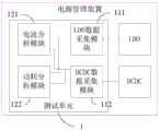
图3为一个实施例提供的电源管理装置的示意图,如图3所示,至少一个数据采集模块11包括LDO数据采集模块111和/或DCDC数据采集模块112;LDO数据采集模块111用于采集电源管理装置中LDO的运行参数;DCDC数据采集模块112用于采集电源管理装置中DCDC的运行参数。FIG. 3 is a schematic diagram of a power management device provided by an embodiment. As shown in FIG. 3 , at least one
需要说明的是,图3中示出了LDO数据采集模块111和DCDC数据采集模块112,在实际场景中,测试单元1可以包括LDO数据采集模块111,也可以包括DCDC数据采集模块112,还可以是包括LDO数据采集模块111和DCDC数据采集模块112这两个模块,还可以包括测量其它电源的数据采集模块,本申请实施例中不以此为限。It should be noted that FIG. 3 shows the LDO
通常情况下,电源管理装置包含LDO和DCDC两类电源。LDO倾向于提供低噪声的、输入和输出线性度较好、而且负载较小和效率较高的电源;而DCDC倾向于向较大的负载提供驱动,同时提供调频和脉宽的两种方式应对负载的不同状态,进而提升电源效率和质量。因此,本实施例中,可以根据实际需求在测试单元1中设置LDO数据采集模块111和/或DCDC数据采集模块112。Usually, the power management device includes two types of power sources, LDO and DCDC. LDOs tend to provide power supplies with low noise, better input and output linearity, and smaller loads and higher efficiency; while DCDCs tend to drive larger loads, while providing two ways of frequency modulation and pulse width. Different states of the load, thereby improving power efficiency and quality. Therefore, in this embodiment, the LDO
LDO数据采集模块111专门应对LDO电源的特点来设计,测量的开始可以通过寄存器来触发,可以监测LDO电源的输入和输出的电流、以及电压状态,测量结果则传到下一级数据分析模块12,作为下一步的计算输入。The LDO
可选地,LDO数据采集模块111还用于采集电源管理装置中系统总电源的运行参数。LDO数据采集模块111还会监测系统总电源(例如电池)的信息,作为总电流和功耗的计算输入。Optionally, the LDO
示例性的,LDO数据采集模块111包括电流传感器、电压传感器和电流镜像电路中的至少一个。可以根据LDO电流的特点来设置不同的测量器件,例如,面对大电流或者小电流,可以采用不同的测量器件组合的方式来完成监测任务,从而实现根据不同大小的电流选择合适的测量器件组合方式,提高测量的准确性和场景普适性。Exemplarily, the LDO
DCDC数据采集模块112专门应对DCDC的特点来设计,可以监测DCDC电源的输入和输出的电流、以及电压状态。因为DCDC电源的开关特性,该DCDC数据采集模块112的数据可以做进一步时钟同步处理,最后才被送到数据分析模块12做最后处理。但是对于DCDC的低功耗模式(例如PWM),它的数据也可以被数据分析模块12直接拾取。该DCDC测试电路模块12的其它功能类似于LDO数据采集模块111。The DCDC
可选地,DCDC数据采集模块112包括电流镜像电路。DCDC数据采集模块112的测量方式更倾向于电流镜像电路,因为DCDC的输入和输出功率通常较大,电流镜像电路测量电流更适合。Optionally, the DCDC
进一步地,DCDC数据采集模块112还用于获取第三时间戳,并根据第三时间戳对DCDC数据采集模块的内部时钟进行校准;第三时间戳为采集DCDC的运行参数的时间戳。Further, the DCDC
本实施例中,由于DCDC电源的开关特性,该DCDC数据采集模块112具有特定的内部时钟,因此,DCDC数据采集模块112在采集数据的同时输出第三时间戳,DCDC数据采集模块112可以将该第三时间戳和系统总时钟的时间戳进行对比,若发现该第三时间戳和系统总时钟的时间戳偏差较大,则可以对该DCDC数据采集模块112的内部时钟进行校准。保证了DCDC数据采集模块112的内部时钟和系统总时钟保持同步,进一步保证了数据采集的准确性以及后期和系统的各种软件行为做嵌入式关联分析的可靠性。In this embodiment, due to the switching characteristics of the DCDC power supply, the DCDC
可选地,还可以设置一个校准模块,用于根据第三时间戳对DCDC数据采集模块的内部时钟进行校准。Optionally, a calibration module may also be set for calibrating the internal clock of the DCDC data acquisition module according to the third time stamp.
本实施例中,可以在测试单元中设置LDO数据采集模块111和/或DCDC数据采集模块112,通过LDO数据采集模块111采集电源管理装置中LDO的运行参数,通过DCDC数据采集模块112采集电源管理装置中DCDC的运行参数,可以根据按照项目、产品或者用例需要来配置LRCPM系统,以及灵活地配置测量内容,实时高效地完成测量过程,并且,可以实现定制化测量。In this embodiment, the LDO
如图4所示,至少一个数据分析模块12包括电流分析模块121和/或功耗分析模块122;电流分析模块121用于对各数据采集模块输出的运行参数中的电流数据进行分析;功耗分析模块122用于根据各数据采集模块输出的运行参数计算各电源的功耗。As shown in FIG. 4 , at least one
需要说明的是,图4中示出了电流分析模块121和功耗分析模块122,在实际场景中,测试单元1可以包括电流分析模块121,也可以包括功耗分析模块122,还可以是包括电流分析模块121和功耗分析模块122这两个模块,还可以包括管理其他测试参数的数据分析模块,本申请实施例中不以此为限。It should be noted that the
本实施例中,电流分析模块121负责所有电流测量结果的计算处理,包括LDO、DCDC和系统总电源的输入和输出电流数据,例如,计算各电源在一段时间内的总电流、对各个电源的各个时刻的电流进行统计等。In this embodiment, the
进一步地,电流分析模块121用于对各数据采集模块输出的运行参数中的电流数据进行分析,包括:电流分析模块121用于根据各数据采集模块输出的运行参数,获取电源管理装置中各电源的电流数据,按照预设的格式对各电源的电流数据进行分析,生成电流测量信息表。Further, the
在本实施例中,之所以有专门的电流处理电路模块121来处理电流,一方面是可以针对不同的数据采集模块设置不同的时钟频率,提升数据采集的精度;另一方面,电流分析模块121可以根据各个数据采集模块测量的电流结果,生成专门的电流测量信息报表,该电流测量报表中可以包括多个电源的电流测量结果,可以进行综合分析、展示各个电源的电流等等。电流分析模块121的数据可以通过PMIC内部总线来访问,以节省电流分析模块121的面积。另外,电流分析模块121计算各路电源电流时可以和系统时钟同步,进而映射到系统软件的行为中,为系统分析提供更好的帮助。In this embodiment, the reason why there is a special current
功耗分析模块122负责所有模块的功耗计算,包括LDO、DCDC和总电源的输入和输出功耗。但是LDO和DCDC由于不同的特性,不同的数据采集模块的测量结果需要基于不同的模型来计算。The power
进一步地,功耗分析模块122用于根据各数据采集模块输出的运行参数计算各电源的功耗,包括:功耗分析模块122用于根据各数据采集模块输出的运行参数,确定各电源的运行参数,以及根据电源的类型和功耗计算模型之间的对应关系,确定各电源的目标功耗计算模型,并将各电源的运行参数输入对应的目标功耗计算模型进行功耗计算,得到各电源的功耗。Further, the power
在本实施例中,可以预先设置电源的类型和功耗计算模型之间的对应关系,功耗分析模块122获取到各个数据采集模块测量得到的各个电源的运行参数之后,根据该对应关系确定各个电源的目标功耗计算模型,将将各电源的运行参数输入对应的目标功耗计算模型进行功耗计算,得到各所电源的功耗。针对不同的电源类型设置不同的功耗计算模型,提高了功耗计算的准确性。In this embodiment, the corresponding relationship between the type of the power supply and the power consumption calculation model may be preset, and the power
进一步地,电流分析模块121和功耗分析模块122可以并行计算,提高计算效率。Further, the
本申请实施例中,测试单元包括电流分析模块121和/或功耗分析模块122,电流分析模块对各数据采集模块输出的运行参数中的电流数据进行分析,功耗分析模块根据各数据采集模块输出的运行参数计算各电源的功耗,通过电流分析模块121和功耗分析模块122实现全自动电流以及功耗的测量和计算,有效地提升了系统测量和分析的效率性,有效地避免了后期开发的工作量。另外,本实施例中的电流分析模块121和功耗分析模块122可以利用LRCPM系统的可编程性,可以根据项目的需要,来设定测量的电源分支和不同的报表形式,提高了系统功耗和其他问题分析的灵活性。In the embodiment of the present application, the test unit includes a
如图5所示,该测试单元1还包括存储模块13,存储模块13用于存储各数据采集模块的配置信息、各数据分析模块的配置信息、以及各数据采集模块采集到的运行参数。As shown in FIG. 5 , the
本实施例中,该存储模块13可以采用寄存器实现,例如,可以为该测试单元1中的每个模块设置一个寄存器,用来存储各个模块的配置信息、各数据分析模块的配置信息、以及各数据采集模块采集到的运行参数等等。可选地,该存储模块可以和外部设备连接,外部设备可以通过寄存器总线访问寄存器,例如,外部设备通过寄存器总线向寄存器输入测量信号,寄存器收到该测量信号触发对应的数据采集模块测量电源的运行参数。例如,当需要测量LDO电源的输入输出电流时,外部设备向存储模块输入LDO测量信号,存储模块根据LDO测量信号找到LDO数据采集模块的寄存器,通过修改该寄存器的值触发LDO数据采集模块进行测试。外部设备可以根据实际的测量需求,通过存储模块中的寄存器触发相应的数据采集模块进行测试,过程简单,也无需增加额外的电路设计。In this embodiment, the
本实施例中,寄存器也都会映射到整个PMIC的寄存器列表内,通过PMIC的寄存器列表可以查看PMIC的中各模块的寄存器。另外,有一些寄存器也会映射到系统状态指示,用来指示PMIC的一些运行状态,供后期分析使用;还有一些寄存器用来暂存它们各数据采集模块的测量值,以供系统处理器延时访问。In this embodiment, the registers are also mapped into the register list of the entire PMIC, and the registers of each module in the PMIC can be viewed through the register list of the PMIC. In addition, some registers are also mapped to the system status indication, which is used to indicate some operating states of the PMIC for later analysis; some registers are used to temporarily store the measured values of their data acquisition modules for the system processor to delay. time visit.
可选地,如图5所示,该测试单元还包括时钟模块14,时钟模块13用于向各PMIC的各个模块输出时钟信号。Optionally, as shown in FIG. 5 , the test unit further includes a
本实施例中,该时钟模块14负责整个PMIC的时钟管理,时钟模块13接收外部设备输入的时钟配置信号,根据该时钟配置信号向PMIC的其它模块输出相应的时钟信号,例如,时钟模块13根据该时钟配置信号向各数据采集模块11和各数据分析模块12输出时钟信号,以实现对整个电源管理装置中各个模块的时钟进行统一管理。In this embodiment, the
进一步地,时钟模块14具体用于根据外部设备输入的时钟配置信号,向PMIC的不同模块输出不同频率的时钟信号。Further, the
在本实施例中,该时钟模块14可以设置、打开或者关闭其他模块的时钟,并且可以根据时钟配置信号为不同模块的提供不同的时钟频率,例如,数据采集模块需要实时测量,可以为数据采集模块配置高速的时钟频率,数据分析模块可以将多次测量数据一起计算分析,可以为数据分析模块配置低速的时钟频率,等等,本实施例中不以此为限。In this embodiment, the
本实施例中,时钟模块根据外部设备输入的时钟配置信号,向PMIC的各个模块输出不同频率的时钟信号,从而为不同的模块提供高速或者低速模式,改变PMIC的采样颗粒度,以提高测量准确性。由于PMIC内置于芯片中,可以实现近距离的测量,采用这种近距离以及与系统时钟同步的测量方式,保证了无损和实时的测量效果。而且,时钟模块统一配置各个模块的时钟,相当于基于系统时钟来测量,系统处理器可以将系统软件的跟踪结果和PMIC的电流、功耗等测量结果同步起来,呈现和分析问题,这会大大提高系统问题分析的效率。In this embodiment, the clock module outputs clock signals of different frequencies to each module of the PMIC according to the clock configuration signal input by the external device, thereby providing high-speed or low-speed modes for different modules, changing the sampling granularity of the PMIC, and improving the measurement accuracy sex. Since the PMIC is built into the chip, it can realize close-range measurement. The use of this close-range measurement method synchronized with the system clock ensures non-destructive and real-time measurement results. Moreover, the clock module configures the clocks of each module uniformly, which is equivalent to measuring based on the system clock. The system processor can synchronize the tracking results of the system software with the measurement results of the current and power consumption of the PMIC, and present and analyze the problem, which will greatly improve the Improve the efficiency of system problem analysis.
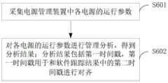
图6为一个实施例提供的电源管理方法的流程图,该方法应用于图2-图5任一实施例所述的电源管理装置中,如图6所示,该电源管理方法可以包括以下步骤:FIG. 6 is a flowchart of a power management method provided by an embodiment, and the method is applied to the power management apparatus described in any of the embodiments of FIG. 2 to FIG. 5 . As shown in FIG. 6 , the power management method may include the following steps :
S601、采集电源管理装置中各电源的运行参数。S601. Collect operating parameters of each power supply in the power management device.
其中,电源管理装置可以包括多个电源,多个电源可以不同类型的电源,也可以是相同类型的电源。运行参数可以包括电源的输入电流、输出电流、电压、剩余电量、温度等。The power management device may include multiple power sources, and the multiple power sources may be different types of power sources, or may be the same type of power sources. The operating parameters may include the input current, output current, voltage, remaining power, temperature, etc. of the power supply.
在本实施例中,如图2-图5任一实施例所示,可以设置在电源管理装置的测试单元设置多个数据采集模块分别采集各个电源的运行参数。例如,一个数据采集模块11测量线性低压降电源(Low Dropout Regulator,LDO)的输入、输出电流、电压、时间戳等,另一个数据采集模块11测量直流电源变换器(Direct circuit to Direct circuit Convertor,DCDC)的输入、输出电流、电压、时间戳等。In this embodiment, as shown in any of the embodiments in FIG. 2 to FIG. 5 , a plurality of data acquisition modules may be set in the test unit of the power management device to collect the operating parameters of each power supply respectively. For example, one
S602、对各电源的运行参数进行管理分析,得到分析结果;分析结果包括第一时间戳,第一时间戳用于和软件跟踪结果中的第二时间戳进行对齐。S602. Perform management analysis on the operating parameters of each power supply to obtain an analysis result; the analysis result includes a first time stamp, and the first time stamp is used to align with the second time stamp in the software tracking result.
其中,分析结果包括第一时间戳,第一时间戳可以为各个数据采集模块采集运行数据的时间戳。软件跟踪结果为在软件运行过程中对软件的各项运行参数进行测量得到的,第二时间戳为测量软件运行参数的时间戳。Wherein, the analysis result includes a first time stamp, and the first time stamp may be a time stamp of the operation data collected by each data collection module. The software tracking result is obtained by measuring various operating parameters of the software during the software running process, and the second time stamp is the time stamp for measuring the software operating parameters.
在本实施例中,可以对采集到的各电源的运行参数进行管理分析,得到携带第一时间戳的分析结果。例如,可以根据每个运行参数被采集时生成的第一时间戳进行归类统计,按照第一时间戳的时间先后顺序将各电源的电流、电压进行归类统计,或者,根据电流、电压计算得到每个电源在每个第一时间戳的功耗,然后将归类后的带有第一时间戳的电流、电压、功耗等信息作为分析结果,将该分析结果中的第一时间戳和软件跟踪结果中的第二时间戳进行对齐,从而实现将PMIC的电源的测量结果和系统的各种软件行为做嵌入式关联分析的目的。In this embodiment, the collected operating parameters of each power supply can be managed and analyzed to obtain an analysis result carrying the first time stamp. For example, classification and statistics can be performed according to the first timestamp generated when each operating parameter is collected, and the current and voltage of each power supply can be classified and counted according to the chronological order of the first timestamp, or calculated according to the current and voltage. Obtain the power consumption of each power supply at each first time stamp, and then use the classified current, voltage, power consumption and other information with the first time stamp as the analysis result, and the first time stamp in the analysis result It is aligned with the second timestamp in the software tracking result, so as to realize the purpose of embedded correlation analysis between the measurement results of the PMIC power supply and various software behaviors of the system.
本申请实施例提供的电源管理方法,采集电源管理装置中电源的运行参数,对各电源的运行参数进行管理分析,得到分析结果,由于该电源管理方法应用于上述电源管理装置,该电源管理装置包括测试单元,测试单元内置于电源管理装置中,可以实时、无损的测量电源管理装置各电源的运行参数,后期无需在电源管理装置外部开发测量电路,减少了后期开发工作量。另外,由于分析结果包括第一时间戳,可以根据第一时间戳和软件跟踪结果中的第二时间戳进行对齐,将测量得到的各电源的运行数据和系统的各种软件行为做嵌入式关联分析。In the power management method provided by the embodiment of the present application, the operating parameters of the power supply in the power management device are collected, the operating parameters of each power supply are managed and analyzed, and the analysis result is obtained. Since the power management method is applied to the above-mentioned power management device, the power management device Including a test unit, the test unit is built in the power management device, which can measure the operating parameters of each power supply of the power management device in real time and non-destructively. There is no need to develop a measurement circuit outside the power management device in the later stage, which reduces the later development workload. In addition, since the analysis result includes the first time stamp, the first time stamp can be aligned with the second time stamp in the software tracking result, and the measured operating data of each power supply can be embedded with various software behaviors of the system. analyze.
通常情况下,电源管理装置包含LDO、DCDC、系统总电源等。可选地,步骤S601“采集电源管理装置中各电源的运行参数”,包括:采集电源管理装置中LDO、DCDC、和系统总电源中的至少一种电源的运行参数。Usually, the power management device includes LDO, DCDC, system total power and so on. Optionally, step S601 of "collecting the operating parameters of each power supply in the power management device" includes: collecting the operating parameters of at least one of the LDO, the DCDC, and the total system power supply in the power management device.
在本实施例中,如图2-图5任一实施例所示,可以针对不同类型的电源设置不同的数据采集模块,例如,LDO数据采集模块111专门应对LDO电源的特点来设计,通过LDO数据采集模块111监测LDO电源的输入和输出的电流、以及电压状态,并且,还可以通过LDO数据采集模块111采集电源管理装置中系统总电源的运行参数。DCDC数据采集模块112专门应对DCDC的特点来设计,可以监测DCDC电源的输入和输出的电流、以及电压状态。In this embodiment, as shown in any of the embodiments in FIG. 2 to FIG. 5 , different data acquisition modules can be set for different types of power supplies. For example, the LDO
进一步地,上述电源管理方法还包括:获取第三时间戳;第三时间戳为采集DCDC的运行参数的时间戳;根据第三时间戳对DCDC数据采集模块的内部时钟进行校准。Further, the above power management method further includes: acquiring a third time stamp; the third time stamp is a time stamp for collecting operating parameters of the DCDC; and calibrating the internal clock of the DCDC data acquisition module according to the third time stamp.
本实施例中,由于DCDC电源的开关特性,在采集DCDC的运行参数的同时,还可以获取采集DCDC的运行参数的第三时间戳,将该第三时间戳和系统总时钟的时间戳进行对比,若发现该第三时间戳和系统总时钟的时间戳偏差较大,则可以对该DCDC数据采集模块的内部时钟进行校准。保证了DCDC数据采集模块112的内部时钟和系统总时钟保持同步,进一步保证了数据采集的准确性以及后期和系统的各种软件行为做嵌入式关联分析的可靠性。In this embodiment, due to the switching characteristics of the DCDC power supply, while collecting the operating parameters of the DCDC, a third time stamp for collecting the operating parameters of the DCDC can also be obtained, and the third time stamp is compared with the time stamp of the total system clock , if it is found that the time stamp between the third time stamp and the total system clock has a large deviation, the internal clock of the DCDC data acquisition module can be calibrated. It is ensured that the internal clock of the DCDC
在其中一个实施例中,步骤S602“对各电源的运行参数进行管理分析”,包括:对各电源的运行参数中的电流数据进行分析;和/或,根据各电源的运行参数计算各电源的功耗。In one embodiment, the step S602 of "managing and analyzing the operating parameters of each power supply" includes: analyzing the current data in the operating parameters of each power supply; and/or, calculating the operating parameters of each power supply according to the operating parameters of each power supply. power consumption.
本实施例中,可以分别对各个电源的运行参数中的不同类型的数据进行分析,也可以是将不同类型的数据结合分析,例如,对各电源的运行参数中的电流数据进行分析,对各电源的运行参数中的电压数据进行分析,或者,根据各电源的运行参数中的电流、电压计算各电源的功耗。In this embodiment, different types of data in the operating parameters of each power supply may be analyzed separately, or different types of data may be analyzed in combination, for example, the current data in the operating parameters of each power supply may be analyzed, and the The voltage data in the operating parameters of the power supply is analyzed, or the power consumption of each power supply is calculated according to the current and voltage in the operating parameters of the power supply.
进一步地,如图7所示,步骤“对各电源的运行参数中的电流数据进行分析”,包括:Further, as shown in Figure 7, the step "analyze the current data in the operating parameters of each power supply" includes:
S701、从各电源的运行参数中获取各电源的电流数据。S701. Acquire current data of each power supply from operating parameters of each power supply.
S702、按照预设的格式对各电源的电流数据进行分析,生成电流测量信息表。S702. Analyze the current data of each power supply according to a preset format, and generate a current measurement information table.
本实施例中,可以对LDO、DCDC和系统总电源等电源的输入和输出电流数据进行分析,例如,计算各电源在一段时间内的总电流、对各个电源的各个时刻的电流进行统计等,根据统计结果生成专门的电流测量信息报表,该电流测量报表中可以包括多个电源的电流测量结果,可以进行综合分析、展示各个电源的电流等等。本实施例中,按照预设各是生成电流测量信息,可以方便在其它外部设备上显示、分析各电源的电流,以及可以方便将各电源的电流和软件跟踪结果中的软件行为进行联合分析。In this embodiment, the input and output current data of power supplies such as LDO, DCDC, and the total system power supply can be analyzed, for example, the total current of each power supply over a period of time can be calculated, and the current of each power supply at each moment can be counted, etc. According to the statistical results, a special current measurement information report is generated. The current measurement report can include the current measurement results of multiple power supplies, and can perform comprehensive analysis and display the current of each power supply. In this embodiment, the current measurement information is generated according to the preset, which can facilitate the display and analysis of the current of each power supply on other external devices, and can facilitate the joint analysis of the current of each power supply and the software behavior in the software tracking result.
进一步地,如图8所示,步骤“根据所述各电源的运行参数计算各所述电源的功耗”,包括:Further, as shown in FIG. 8 , the step “calculate the power consumption of each of the power supplies according to the operating parameters of the power supplies” includes:
S801、根据电源的类型和功耗计算模型之间的对应关系,确定各电源的目标功耗计算模型。S801. Determine a target power consumption calculation model of each power source according to the correspondence between the type of the power source and the power consumption calculation model.
S802、将各电源的运行参数输入对应的目标功耗计算模型进行功耗计算,得到各电源的功耗。S802. Input the operating parameters of each power supply into a corresponding target power consumption calculation model to perform power consumption calculation, and obtain the power consumption of each power supply.
本实施例中,由于LDO、DCDC、系统总电源等的电源特性不同,故不同的电源的运行参数需要不同的功耗模型来计算功耗。可以预先设置各电源的类型和功耗计算模型之间的对应关系,获取到各个电源的运行参数之后,根据该对应关系确定各个电源的目标功耗计算模型,将将各电源的运行参数输入对应的目标功耗计算模型进行功耗计算,得到各所电源的功耗。针对不同的电源类型设置不同的功耗计算模型,提高了功耗计算的准确性。In this embodiment, since the power characteristics of the LDO, the DCDC, and the total system power supply are different, different power consumption models are required to calculate the power consumption for the operating parameters of the different power supplies. The corresponding relationship between the type of each power supply and the power consumption calculation model can be preset, and after the operating parameters of each power supply are obtained, the target power consumption calculation model of each power supply is determined according to the corresponding relationship, and the operating parameters of each power supply are input corresponding. The target power consumption calculation model is used to calculate the power consumption to obtain the power consumption of each power supply. Different power consumption calculation models are set for different power types, which improves the accuracy of power consumption calculation.
在上述实施例的基础上,为了更好地将电源的分析结果和软件跟踪结果进行联合分析,可以将分析结果输出给外部设备。可选地,上述电源管理方法还包括:向外部设备输出分析结果;分析结果包括携带第一时间戳的电流信息和/或功耗信息;外部设备用于对第一时间戳和软件跟踪结果中的第二时间戳进行对齐,确定并显示各任务执行过程中对应电源的电流信息和/或功耗信息。On the basis of the above embodiment, in order to better perform joint analysis on the analysis result of the power supply and the software tracking result, the analysis result may be output to an external device. Optionally, the above power management method further includes: outputting an analysis result to an external device; the analysis result includes current information and/or power consumption information carrying the first timestamp; The second time stamps are aligned, and the current information and/or power consumption information of the corresponding power supply during the execution of each task is determined and displayed.
本实施例中,在对电源管理装置的各个电源的运行参数进行测量以及分析时,还会对系统的软件进行跟踪测量,获取软件跟踪结果。将各电源的运行参数的分析结果输出给外部设备,由外部设备对电源的运行参数和软件跟踪结果进行联合分析,例如,将第一时间戳和第二时间戳进行对齐,将对齐的第一时间戳的电源数据和第二时间戳的软件运行数据对应显示和分析,方便用户查看软件运行状态,也可以根据对齐的第一时间戳的电源数据和第二时间戳的软件运行数据分析软件运行过程中是否出现故障等问题,将电源的运行参数的分析结果和软件跟踪结果进行联合分析,从而保证软件运行的可靠性。In this embodiment, when the operating parameters of each power supply of the power management device are measured and analyzed, the software of the system is also tracked and measured to obtain the software tracking result. Output the analysis results of the operating parameters of each power supply to the external device, and the external device will jointly analyze the operating parameters of the power supply and the software tracking results, for example, align the first time stamp with the second time stamp, The time-stamped power supply data and the second time-stamped software operation data are displayed and analyzed correspondingly, which is convenient for users to view the software operation status. The software operation can also be analyzed according to the aligned first time-stamped power supply data and the second time-stamped software operation data. Whether there is a fault in the process, the analysis results of the operating parameters of the power supply and the software tracking results are jointly analyzed to ensure the reliability of the software operation.
应该理解的是,虽然图6-图8的流程图中的各个步骤按照箭头的指示依次显示,但是这些步骤并不是必然按照箭头指示的顺序依次执行。除非本文中有明确的说明,这些步骤的执行并没有严格的顺序限制,这些步骤可以以其它的顺序执行。而且,图6-图8中的至少一部分步骤可以包括多个子步骤或者多个阶段,这些子步骤或者阶段并不必然是在同一时刻执行完成,而是可以在不同的时刻执行,这些子步骤或者阶段的执行顺序也不必然是依次进行,而是可以与其它步骤或者其它步骤的子步骤或者阶段的至少一部分轮流或者交替地执行。It should be understood that although the steps in the flowcharts of FIGS. 6-8 are sequentially displayed according to the arrows, these steps are not necessarily executed in the order indicated by the arrows. Unless explicitly stated herein, the execution of these steps is not strictly limited to the order, and these steps may be performed in other orders. Moreover, at least a part of the steps in FIG. 6-FIG. 8 may include multiple sub-steps or multiple stages. These sub-steps or stages are not necessarily executed at the same time, but may be executed at different times. These sub-steps or The order of execution of the stages is also not necessarily sequential, but may be performed alternately or alternately with other steps or sub-steps of other steps or at least a portion of a stage.
以上所述实施例仅表达了本申请的几种实施方式,其描述较为具体和详细,但并不能因此而理解为对本申请专利范围的限制。应当指出的是,对于本领域的普通技术人员来说,在不脱离本申请构思的前提下,还可以做出若干变形和改进,这些都属于本申请的保护范围。因此,本申请专利的保护范围应以所附权利要求为准。The above-mentioned embodiments only represent several embodiments of the present application, and the descriptions thereof are relatively specific and detailed, but should not be construed as a limitation on the scope of the patent of the present application. It should be pointed out that for those skilled in the art, without departing from the concept of the present application, several modifications and improvements can be made, which all belong to the protection scope of the present application. Therefore, the scope of protection of the patent of the present application shall be subject to the appended claims.
Claims (17)
Priority Applications (2)
| Application Number | Priority Date | Filing Date | Title |
|---|---|---|---|
| CN202010857061.5ACN112034376B (en) | 2020-08-24 | 2020-08-24 | Power management apparatus and method |
| PCT/CN2021/106496WO2022042116A1 (en) | 2020-08-24 | 2021-07-15 | Power management apparatus and method |
Applications Claiming Priority (1)
| Application Number | Priority Date | Filing Date | Title |
|---|---|---|---|
| CN202010857061.5ACN112034376B (en) | 2020-08-24 | 2020-08-24 | Power management apparatus and method |
Publications (2)
| Publication Number | Publication Date |
|---|---|
| CN112034376Atrue CN112034376A (en) | 2020-12-04 |
| CN112034376B CN112034376B (en) | 2023-08-29 |
Family
ID=73580504
Family Applications (1)
| Application Number | Title | Priority Date | Filing Date |
|---|---|---|---|
| CN202010857061.5AActiveCN112034376B (en) | 2020-08-24 | 2020-08-24 | Power management apparatus and method |
Country Status (2)
| Country | Link |
|---|---|
| CN (1) | CN112034376B (en) |
| WO (1) | WO2022042116A1 (en) |
Cited By (1)
| Publication number | Priority date | Publication date | Assignee | Title |
|---|---|---|---|---|
| WO2022042116A1 (en)* | 2020-08-24 | 2022-03-03 | 哲库科技(北京)有限公司 | Power management apparatus and method |
Citations (20)
| Publication number | Priority date | Publication date | Assignee | Title |
|---|---|---|---|---|
| US20050060403A1 (en)* | 2003-09-11 | 2005-03-17 | Bernstein David R. | Time-based correlation of non-translative network segments |
| JP2008067576A (en)* | 2006-09-11 | 2008-03-21 | Fuji Xerox Co Ltd | Power supply monitoring device |
| CN201570893U (en)* | 2009-11-03 | 2010-09-01 | 中兴通讯股份有限公司 | Power supply device |
| WO2010105087A1 (en)* | 2009-03-11 | 2010-09-16 | Enfora, Inc. | Power consumption for battery-operated devices |
| US20100233989A1 (en)* | 2009-03-11 | 2010-09-16 | Scott Douglas Constien | Methods and apparatus for modeling, monitoring, estimating and controlling power consumption in battery-operated devices |
| CN202421477U (en)* | 2011-12-14 | 2012-09-05 | 中国广东核电集团有限公司 | Device for detecting power supply reliability of nuclear power station |
| CN102842915A (en)* | 2012-08-23 | 2012-12-26 | 天津大学 | Grid-connected inverter with information integration function |
| CN103165201A (en)* | 2011-12-14 | 2013-06-19 | 中国广东核电集团有限公司 | Nuclear power station power supply detection system and method |
| CN105093080A (en)* | 2015-08-27 | 2015-11-25 | 国家电网公司 | Distributed wireless synchronous zinc oxide lightning arrester online monitoring apparatus |
| CN105470590A (en)* | 2014-09-05 | 2016-04-06 | 宇龙计算机通信科技(深圳)有限公司 | Method and device for managing battery parameters |
| JP2016062351A (en)* | 2014-09-18 | 2016-04-25 | 日本電気株式会社 | Monitor circuit, logic analysis terminal and system, and delay measuring method and program |
| CN107121645A (en)* | 2017-03-23 | 2017-09-01 | 国家电网公司 | A kind of high-tension switch gear and electrical power monitoring device |
| CN108521837A (en)* | 2016-12-20 | 2018-09-11 | 深圳市浩博高科技有限公司 | A kind of method for managing power supply, device and micro-energy charger based on micro-energy acquisition |
| JP6403351B1 (en)* | 2017-04-07 | 2018-10-10 | 株式会社ミニ・ソリューション | Power monitoring system |
| US20190033354A1 (en)* | 2017-07-26 | 2019-01-31 | Panoramic Power Ltd. | System and method for transmission of time stamps of current samples sampled by a self-powered power sensor |
| CN109557447A (en)* | 2018-09-13 | 2019-04-02 | 深圳市卓精微智能机器人设备有限公司 | A kind of power management class IC test macro |
| WO2019138425A1 (en)* | 2018-01-10 | 2019-07-18 | Ramanujan Kadambi Sarangapani | Networked battery for high energy applications |
| CN110943796A (en)* | 2019-11-19 | 2020-03-31 | 深圳市道通智能航空技术有限公司 | Timestamp alignment method, timestamp alignment device, storage medium and equipment |
| CN111142008A (en)* | 2019-12-31 | 2020-05-12 | 京信通信系统(中国)有限公司 | Circuit board power supply parameter testing system and method |
| US20200186038A1 (en)* | 2017-08-18 | 2020-06-11 | Huawei Technologies Co., Ltd. | Troubleshooting method and apparatus for power supply device |
Family Cites Families (7)
| Publication number | Priority date | Publication date | Assignee | Title |
|---|---|---|---|---|
| US7385797B1 (en)* | 2004-05-27 | 2008-06-10 | Sun Microsystems, Inc. | Power problem diagnosis |
| JP4926857B2 (en)* | 2007-06-29 | 2012-05-09 | 中国電力株式会社 | Power feeding system and method for controlling power feeding system |
| US9158720B2 (en)* | 2013-08-11 | 2015-10-13 | Qualcomm Incorporated | System and method for scalable trace unit timestamping |
| WO2019040832A1 (en)* | 2017-08-25 | 2019-02-28 | Volley Media, Llc | METHODS AND SYSTEMS FOR SHARING LIVE FLOW MULTIMEDIA CONTENT |
| CN110263535B (en)* | 2019-06-18 | 2021-03-30 | 长安大学 | Embedded hardware assisted tracking track synchronization method in distributed environment |
| CN112034376B (en)* | 2020-08-24 | 2023-08-29 | 哲库科技(北京)有限公司 | Power management apparatus and method |
| CN113176973B (en)* | 2021-05-14 | 2023-04-25 | 山东英信计算机技术有限公司 | PSU power supply black box log time stamp recording method, device, equipment and medium |
- 2020
- 2020-08-24CNCN202010857061.5Apatent/CN112034376B/enactiveActive
- 2021
- 2021-07-15WOPCT/CN2021/106496patent/WO2022042116A1/ennot_activeCeased
Patent Citations (20)
| Publication number | Priority date | Publication date | Assignee | Title |
|---|---|---|---|---|
| US20050060403A1 (en)* | 2003-09-11 | 2005-03-17 | Bernstein David R. | Time-based correlation of non-translative network segments |
| JP2008067576A (en)* | 2006-09-11 | 2008-03-21 | Fuji Xerox Co Ltd | Power supply monitoring device |
| WO2010105087A1 (en)* | 2009-03-11 | 2010-09-16 | Enfora, Inc. | Power consumption for battery-operated devices |
| US20100233989A1 (en)* | 2009-03-11 | 2010-09-16 | Scott Douglas Constien | Methods and apparatus for modeling, monitoring, estimating and controlling power consumption in battery-operated devices |
| CN201570893U (en)* | 2009-11-03 | 2010-09-01 | 中兴通讯股份有限公司 | Power supply device |
| CN202421477U (en)* | 2011-12-14 | 2012-09-05 | 中国广东核电集团有限公司 | Device for detecting power supply reliability of nuclear power station |
| CN103165201A (en)* | 2011-12-14 | 2013-06-19 | 中国广东核电集团有限公司 | Nuclear power station power supply detection system and method |
| CN102842915A (en)* | 2012-08-23 | 2012-12-26 | 天津大学 | Grid-connected inverter with information integration function |
| CN105470590A (en)* | 2014-09-05 | 2016-04-06 | 宇龙计算机通信科技(深圳)有限公司 | Method and device for managing battery parameters |
| JP2016062351A (en)* | 2014-09-18 | 2016-04-25 | 日本電気株式会社 | Monitor circuit, logic analysis terminal and system, and delay measuring method and program |
| CN105093080A (en)* | 2015-08-27 | 2015-11-25 | 国家电网公司 | Distributed wireless synchronous zinc oxide lightning arrester online monitoring apparatus |
| CN108521837A (en)* | 2016-12-20 | 2018-09-11 | 深圳市浩博高科技有限公司 | A kind of method for managing power supply, device and micro-energy charger based on micro-energy acquisition |
| CN107121645A (en)* | 2017-03-23 | 2017-09-01 | 国家电网公司 | A kind of high-tension switch gear and electrical power monitoring device |
| JP6403351B1 (en)* | 2017-04-07 | 2018-10-10 | 株式会社ミニ・ソリューション | Power monitoring system |
| US20190033354A1 (en)* | 2017-07-26 | 2019-01-31 | Panoramic Power Ltd. | System and method for transmission of time stamps of current samples sampled by a self-powered power sensor |
| US20200186038A1 (en)* | 2017-08-18 | 2020-06-11 | Huawei Technologies Co., Ltd. | Troubleshooting method and apparatus for power supply device |
| WO2019138425A1 (en)* | 2018-01-10 | 2019-07-18 | Ramanujan Kadambi Sarangapani | Networked battery for high energy applications |
| CN109557447A (en)* | 2018-09-13 | 2019-04-02 | 深圳市卓精微智能机器人设备有限公司 | A kind of power management class IC test macro |
| CN110943796A (en)* | 2019-11-19 | 2020-03-31 | 深圳市道通智能航空技术有限公司 | Timestamp alignment method, timestamp alignment device, storage medium and equipment |
| CN111142008A (en)* | 2019-12-31 | 2020-05-12 | 京信通信系统(中国)有限公司 | Circuit board power supply parameter testing system and method |
Non-Patent Citations (4)
| Title |
|---|
| 唐盛: "新一代逆变电源智能监控系统研究", 《中国优秀博硕士学位论文全文数据库(硕士) 工程科技Ⅱ辑》* |
| 唐盛: "新一代逆变电源智能监控系统研究", 《中国优秀博硕士学位论文全文数据库(硕士) 工程科技Ⅱ辑》, no. 11, 15 November 2011 (2011-11-15), pages 042 - 61* |
| 邹政耀 等: "《新能源汽车技术》", 31 July 2012, 国防工业出版社, pages: 239 - 240* |
| 阿申登: "《VHDL嵌入式数字系统设计教程》", 30 April 2011, 北京航空航天大学出版社, pages: 18* |
Cited By (1)
| Publication number | Priority date | Publication date | Assignee | Title |
|---|---|---|---|---|
| WO2022042116A1 (en)* | 2020-08-24 | 2022-03-03 | 哲库科技(北京)有限公司 | Power management apparatus and method |
Also Published As
| Publication number | Publication date |
|---|---|
| CN112034376B (en) | 2023-08-29 |
| WO2022042116A1 (en) | 2022-03-03 |
Similar Documents
| Publication | Publication Date | Title |
|---|---|---|
| Prieto et al. | Self-powered wireless sensor applied to gear diagnosis based on acoustic emission | |
| CN110441584A (en) | Equipment running state monitoring method, device, storage medium and system | |
| CN108322737B (en) | Method and device for measuring camera shooting frame rate | |
| CN105629052B (en) | Chip power-consumption real-time detection method | |
| CN106405460A (en) | Electronic instrument voltage detection calibration system and calibration method | |
| CN103364629B (en) | A kind of electronic device energy consumption measuring method and system | |
| US10528109B2 (en) | System and method for determining power loads | |
| Diouri et al. | Assessing power monitoring approaches for energy and power analysis of computers | |
| CN112034376B (en) | Power management apparatus and method | |
| Köhler et al. | Pinpoint the joules: Unifying runtime-support for energy measurements on heterogeneous systems | |
| Tufts et al. | The threshold analysis of SVD-based algorithms | |
| Almeida et al. | Energy monitoring as an essential building block towards sustainable ultrascale systems | |
| CN117785587A (en) | Power consumption testing method and device for embedded device and storage medium | |
| CN206805286U (en) | A kind of device of DCS system simulations amount signal acquisition browsing real-time data | |
| CN116430271A (en) | An online detection method, intelligent terminal and storage medium for LED flexible light bar | |
| US9032129B2 (en) | Advanced energy profiler | |
| CN104180894A (en) | Railway environment vibration real-time monitoring and analyzing system | |
| CN110888100A (en) | A single-phase smart energy meter online on-load detection system and method | |
| CN211372867U (en) | Refrigerator monitoring device | |
| Dzhagaryan et al. | An environment for automated measurement of energy consumed by mobile and embedded computing devices | |
| CN104515956A (en) | Method and device for detecting intelligent ammeter power module | |
| CN116955045B (en) | Remote JTAG multiplexing test method and system | |
| El Outmani et al. | Monitoring energy consumption of android apps with AppsDrain | |
| El Kouche et al. | Energy consumption measurements and reduction of Zigbee based wireless sensor networks | |
| CN113834996A (en) | Parameter measuring method and device for burn-in test of power device and electronic equipment |
Legal Events
| Date | Code | Title | Description |
|---|---|---|---|
| PB01 | Publication | ||
| PB01 | Publication | ||
| SE01 | Entry into force of request for substantive examination | ||
| SE01 | Entry into force of request for substantive examination | ||
| TA01 | Transfer of patent application right | Effective date of registration:20201211 Address after:Room 1501, 15 / F, building 2, No. 10 yard, Chaoyang Park South Road, Chaoyang District, Beijing Applicant after:Zheku Technology (Beijing) Co.,Ltd. Address before:Changan town in Guangdong province Dongguan 523860 usha Beach Road No. 18 Applicant before:GUANGDONG OPPO MOBILE TELECOMMUNICATIONS Corp.,Ltd. | |
| TA01 | Transfer of patent application right | ||
| GR01 | Patent grant | ||
| GR01 | Patent grant | ||
| TR01 | Transfer of patent right | Effective date of registration:20241108 Address after:6th Floor, No.1 Chongqing Road, Banqiao District, Xinbei City, Taiwan, China, China Patentee after:Weiguang Co.,Ltd. Country or region after:Samoa Address before:Room 1501, 15 / F, building 2, No. 10 yard, Chaoyang Park South Road, Chaoyang District, Beijing Patentee before:Zheku Technology (Beijing) Co.,Ltd. Country or region before:China | |
| TR01 | Transfer of patent right |