CN112032332A - Sterilizing tap - Google Patents
Sterilizing tapDownload PDFInfo
- Publication number
- CN112032332A CN112032332ACN202011028644.3ACN202011028644ACN112032332ACN 112032332 ACN112032332 ACN 112032332ACN 202011028644 ACN202011028644 ACN 202011028644ACN 112032332 ACN112032332 ACN 112032332A
- Authority
- CN
- China
- Prior art keywords
- water
- faucet
- plate
- cavity
- sterilizing
- Prior art date
- Legal status (The legal status is an assumption and is not a legal conclusion. Google has not performed a legal analysis and makes no representation as to the accuracy of the status listed.)
- Pending
Links
Images


Classifications
- F—MECHANICAL ENGINEERING; LIGHTING; HEATING; WEAPONS; BLASTING
- F16—ENGINEERING ELEMENTS AND UNITS; GENERAL MEASURES FOR PRODUCING AND MAINTAINING EFFECTIVE FUNCTIONING OF MACHINES OR INSTALLATIONS; THERMAL INSULATION IN GENERAL
- F16K—VALVES; TAPS; COCKS; ACTUATING-FLOATS; DEVICES FOR VENTING OR AERATING
- F16K3/00—Gate valves or sliding valves, i.e. cut-off apparatus with closing members having a sliding movement along the seat for opening and closing
- F16K3/02—Gate valves or sliding valves, i.e. cut-off apparatus with closing members having a sliding movement along the seat for opening and closing with flat sealing faces; Packings therefor
- F16K3/04—Gate valves or sliding valves, i.e. cut-off apparatus with closing members having a sliding movement along the seat for opening and closing with flat sealing faces; Packings therefor with pivoted closure members
- F16K3/06—Gate valves or sliding valves, i.e. cut-off apparatus with closing members having a sliding movement along the seat for opening and closing with flat sealing faces; Packings therefor with pivoted closure members in the form of closure plates arranged between supply and discharge passages
- F16K3/08—Gate valves or sliding valves, i.e. cut-off apparatus with closing members having a sliding movement along the seat for opening and closing with flat sealing faces; Packings therefor with pivoted closure members in the form of closure plates arranged between supply and discharge passages with circular plates rotatable around their centres
- C—CHEMISTRY; METALLURGY
- C02—TREATMENT OF WATER, WASTE WATER, SEWAGE, OR SLUDGE
- C02F—TREATMENT OF WATER, WASTE WATER, SEWAGE, OR SLUDGE
- C02F1/00—Treatment of water, waste water, or sewage
- C02F1/001—Processes for the treatment of water whereby the filtration technique is of importance
- C—CHEMISTRY; METALLURGY
- C02—TREATMENT OF WATER, WASTE WATER, SEWAGE, OR SLUDGE
- C02F—TREATMENT OF WATER, WASTE WATER, SEWAGE, OR SLUDGE
- C02F1/00—Treatment of water, waste water, or sewage
- C02F1/50—Treatment of water, waste water, or sewage by addition or application of a germicide or by oligodynamic treatment
- E—FIXED CONSTRUCTIONS
- E03—WATER SUPPLY; SEWERAGE
- E03C—DOMESTIC PLUMBING INSTALLATIONS FOR FRESH WATER OR WASTE WATER; SINKS
- E03C1/00—Domestic plumbing installations for fresh water or waste water; Sinks
- E03C1/02—Plumbing installations for fresh water
- E03C1/04—Water-basin installations specially adapted to wash-basins or baths
- E03C1/0404—Constructional or functional features of the spout
- F—MECHANICAL ENGINEERING; LIGHTING; HEATING; WEAPONS; BLASTING
- F16—ENGINEERING ELEMENTS AND UNITS; GENERAL MEASURES FOR PRODUCING AND MAINTAINING EFFECTIVE FUNCTIONING OF MACHINES OR INSTALLATIONS; THERMAL INSULATION IN GENERAL
- F16K—VALVES; TAPS; COCKS; ACTUATING-FLOATS; DEVICES FOR VENTING OR AERATING
- F16K27/00—Construction of housing; Use of materials therefor
- F16K27/04—Construction of housing; Use of materials therefor of sliding valves
- F16K27/044—Construction of housing; Use of materials therefor of sliding valves slide valves with flat obturating members
- F16K27/045—Construction of housing; Use of materials therefor of sliding valves slide valves with flat obturating members with pivotal obturating members
- F—MECHANICAL ENGINEERING; LIGHTING; HEATING; WEAPONS; BLASTING
- F16—ENGINEERING ELEMENTS AND UNITS; GENERAL MEASURES FOR PRODUCING AND MAINTAINING EFFECTIVE FUNCTIONING OF MACHINES OR INSTALLATIONS; THERMAL INSULATION IN GENERAL
- F16K—VALVES; TAPS; COCKS; ACTUATING-FLOATS; DEVICES FOR VENTING OR AERATING
- F16K3/00—Gate valves or sliding valves, i.e. cut-off apparatus with closing members having a sliding movement along the seat for opening and closing
- F16K3/30—Details
Landscapes
- Engineering & Computer Science (AREA)
- General Engineering & Computer Science (AREA)
- Mechanical Engineering (AREA)
- Life Sciences & Earth Sciences (AREA)
- Hydrology & Water Resources (AREA)
- Water Supply & Treatment (AREA)
- Environmental & Geological Engineering (AREA)
- Chemical & Material Sciences (AREA)
- Organic Chemistry (AREA)
- Health & Medical Sciences (AREA)
- Public Health (AREA)
- Treatment Of Water By Oxidation Or Reduction (AREA)
Abstract
Translated fromChinese
Description
Translated fromChinese技术领域technical field
本发明涉及水龙头技术领域,具体地说,涉及一种灭菌龙头。The invention relates to the technical field of faucets, in particular to a sterilization faucet.
背景技术Background technique
我国净水器的普及度越来越高,由于目前市场上的净水器多以物理过滤为主,净水器的滤芯在过滤杂质的同时会把自来水中原有的消毒剂“氯”去除,使得净水器自身及过滤后的水更容易滋生细菌,不能作为饮用水直接饮用。The popularity of water purifiers in my country is getting higher and higher. Because most of the water purifiers on the market are mainly physical filtration, the filter element of the water purifier will remove the original disinfectant "chlorine" in the tap water while filtering impurities. It makes the water purifier itself and the filtered water more likely to breed bacteria, and cannot be directly consumed as drinking water.
对此有少数净水器集成灭菌功能,如采用紫外线杀菌和电晕法臭氧杀菌。由于紫外线净水器功率较低,对于流速较快的净水并不能够起到杀菌作用。而电晕法臭氧发生器是从空气中产生臭氧,产生臭氧的同时会将空气中的氮(N)反应生成有毒的氮氧化物,在欧美、日本等国家严禁电晕法臭氧应用在食品领域。另外,上述集成灭菌功能的净水器价格较高,对于已安装有物理过滤净水器的用户,若直接整体更换净水器则会造成不必要浪费,同时更换成本高昂。In this regard, a few water purifiers have integrated sterilization functions, such as ultraviolet sterilization and corona ozone sterilization. Due to the low power of the UV water purifier, it cannot sterilize the water with fast flow rate. The corona method ozone generator generates ozone from the air, and at the same time, it will react nitrogen (N) in the air to form toxic nitrogen oxides. In Europe, America, Japan and other countries, the application of corona method ozone in the food field is strictly prohibited. . In addition, the above-mentioned water purifiers with integrated sterilization function are expensive. For users who have installed physical filtration water purifiers, if the water purifier is directly replaced as a whole, unnecessary waste will be caused, and the replacement cost will be high.
发明内容SUMMARY OF THE INVENTION
本发明的目的在于提供一种灭菌龙头,对过滤净水进行杀菌消毒。The purpose of the present invention is to provide a sterilizing faucet for sterilizing and sterilizing filtered purified water.
本发明公开的灭菌龙头所采用的技术方案是:The technical scheme adopted by the sterilizing faucet disclosed by the present invention is:
一种灭菌龙头,包括:龙头主体,包括通水腔,所述通水腔下端设进水口,上端设出水口,所述通水腔一侧设有隔板;水解臭氧发生器,包括板体部和安装于板体部的电极部,所述板体部固定于隔板,所述电极部穿过隔板伸入通水腔内;以及龙头开关,设于龙头主体上,用于关闭或打开进水口。A sterilizing faucet, comprising: a faucet body, including a water passage cavity, a water inlet at the lower end of the water passage chamber, a water outlet at the upper end, and a partition plate on one side of the water passage chamber; a hydrolysis ozone generator, including a plate a body part and an electrode part installed on the plate body part, the plate body part is fixed on the separator, the electrode part extends into the water passage cavity through the separator; or open the water inlet.
作为优选方案,还包括水位探针、与水位探针信号连接的PCB板,所述水位探针设于隔板,所述水位探针的探针部穿过隔板伸入通水腔内,所述水位探针的探针部安装高度高于水解臭氧发生器的电极部安装高度。As a preferred solution, it also includes a water level probe and a PCB board signally connected to the water level probe, the water level probe is arranged on the partition plate, and the probe part of the water level probe extends into the water passage cavity through the partition plate, The installation height of the probe part of the water level probe is higher than the installation height of the electrode part of the hydrolysis ozone generator.
作为优选方案,还包括水质探针,所述水质探针设于隔板,并与PCB板信号连接,所述水质探针的探针部穿过隔板伸入通水腔内。As a preferred solution, a water quality probe is also included, the water quality probe is arranged on the partition plate and is signal-connected to the PCB board, and the probe part of the water quality probe extends into the water passage cavity through the partition plate.
作为优选方案,所述龙头开关内设霍尔开关,所述霍尔开关与PCB板信号连接。As a preferred solution, the faucet switch is provided with a Hall switch, and the Hall switch is signal-connected to the PCB board.
作为优选方案,所述PCB板上设至少一LED灯,所述LED灯用于根据水质探针的检测信息发出不同颜色的光。As a preferred solution, at least one LED light is provided on the PCB board, and the LED light is used to emit light of different colors according to the detection information of the water quality probe.
作为优选方案,所述隔板远离通水腔一侧形成隔水腔,所述水解臭氧发生器的板体部、PCB板位于隔水腔内。As a preferred solution, a water-proof cavity is formed on the side of the partition plate away from the water-passing cavity, and the plate body and the PCB board of the hydrolysis ozone generator are located in the water-proof cavity.
作为优选方案,所述隔水腔的腔体上设显示面板,所述显示面板设置在隔水腔的远离隔板一端。As a preferred solution, a display panel is arranged on the cavity of the water-proof cavity, and the display panel is arranged at one end of the water-proof cavity away from the partition plate.
作为优选方案,所述板体部与隔板之间设防水圈。As a preferred solution, a waterproof ring is arranged between the plate body portion and the separator.
作为优选方案,所述通水腔进水口与进水管连接;所述通水腔进水口包括与进水管连通的第一通道、与通水腔连通的第二通道,所述第一通道与第二通道均与龙头开关连接。As a preferred solution, the water inlet of the water passage is connected to the water inlet pipe; the water inlet of the water passage comprises a first channel communicated with the water inlet pipe and a second channel communicated with the water passage, and the first channel is connected to the second channel. Both channels are connected to the tap switch.
作为优选方案,所述板体部包括安装板,所述电极部包括负极片、正极片以及分隔块;所述负极片和正极片均设有若干片,其中每一所述正极片设于相邻负极片之间,且每一所述正极片与相邻的负极片之间保持一预设间隙;所述负极片和正极片的一端设于安装板,所述负极片和正极片的相对另一端上均形成有缺口,所述分隔块设于缺口处;所述分隔块上开设有若干相互间隔的环形凹槽,所述负极片和正极片的另一端分别伸入一环形凹槽内。As a preferred solution, the plate body portion includes a mounting plate, and the electrode portion includes a negative electrode sheet, a positive electrode sheet, and a separator block; both the negative electrode sheet and the positive electrode sheet are provided with a plurality of sheets, and each of the positive electrode sheets is provided in a phase between adjacent negative electrode sheets, and a preset gap is maintained between each of the positive electrode sheets and the adjacent negative electrode sheets; one end of the negative electrode sheet and the positive electrode sheet is set on the mounting plate, and the opposite A gap is formed on the other end, and the separating block is arranged at the gap; a plurality of annular grooves spaced from each other are opened on the separating block, and the other ends of the negative electrode sheet and the positive electrode sheet respectively extend into an annular groove. .
本发明公开的灭菌龙头的有益效果是:水解臭氧发生器包括板体部和电极部,将板体部固定于隔板,使电极部穿过隔板伸入通水腔内,水被阻隔在通水腔内。打开水龙头,使水解臭氧发生器工作产生臭氧,臭氧对净水进行灭菌消毒,灭菌消毒后的净水自通水腔的出水口流出。本产品无需更换净水器,降低了更换成本,且由于出水经过了过滤和臭氧灭菌消毒,因此可直接饮用,另外臭氧极易溶于水,臭氧在水中迅速分解为氧气,在杀菌的同时增加水中的氧含量。The beneficial effect of the sterilizing faucet disclosed by the present invention is that the hydrolysis ozone generator includes a plate body part and an electrode part, and the plate body part is fixed on the separator, so that the electrode part extends into the water passage cavity through the separator, and the water is blocked in the water chamber. Turn on the faucet to make the hydrolysis ozone generator work to generate ozone, the ozone sterilizes the purified water, and the purified water after sterilization and disinfection flows out from the water outlet of the water passage. This product does not need to replace the water purifier, which reduces the replacement cost, and because the effluent has been filtered and sterilized by ozone, it can be directly consumed. In addition, ozone is easily soluble in water, and ozone is rapidly decomposed into oxygen in water. Increases the oxygen level in the water.
附图说明Description of drawings
图1是本发明灭菌龙头的结构示意图。FIG. 1 is a schematic structural diagram of the sterilization faucet of the present invention.
图2是本发明灭菌龙头的爆炸结构示意图。Fig. 2 is the exploded structure schematic diagram of the sterilization faucet of the present invention.
图3是本发明灭菌龙头的隔板的结构示意图。FIG. 3 is a schematic structural diagram of the partition plate of the sterilization faucet of the present invention.
图4是本发明灭菌龙头的剖视图。Fig. 4 is a cross-sectional view of the sterilizing faucet of the present invention.
图5是本发明灭菌龙头的另一视角的剖视图。Figure 5 is a cross-sectional view from another perspective of the sterilizing faucet of the present invention.
图6是本发明灭菌龙头的水解臭氧发生器的结构示意图。FIG. 6 is a schematic structural diagram of the hydrolysis ozone generator of the sterilization faucet of the present invention.
图7是本发明灭菌龙头的水解臭氧发生器的侧视图。Fig. 7 is a side view of the hydrolysis ozone generator of the sterilizing faucet of the present invention.
图8是本发明灭菌龙头的水解臭氧发生器的爆炸结构示意图。8 is a schematic diagram of the explosion structure of the hydrolysis ozone generator of the sterilization faucet of the present invention.
图9是本发明灭菌龙头的水解臭氧发生器的安装板的仰视图。Fig. 9 is a bottom view of the mounting plate of the hydrolysis ozone generator of the sterilizing faucet of the present invention.
具体实施方式Detailed ways
下面结合具体实施例和说明书附图对本发明做进一步阐述和说明:Below in conjunction with specific embodiment and description accompanying drawing, the present invention will be further elaborated and described:
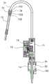
请参考图1和图2,一种灭菌龙头,包括龙头主体10、水解臭氧发生器20、水位探针30、水质探针40、龙头开关50以及PCB板60。Please refer to FIGS. 1 and 2 , a sterilization faucet includes a
请参考图3和图4,龙头主体10包括通水腔11,通水腔11一侧设有隔板13。通水腔11下端设进水口,上端设出水口。隔板13远离通水腔11一侧形成隔水腔12。即隔板13位于通水腔11、隔水腔12之间。本实施例中,通水腔11截面为近似圆柱状,隔水腔12设于通水腔11一侧,隔水腔12截面呈近似椭圆形。Please refer to FIG. 3 and FIG. 4 , the
请参考图2和图4,水解臭氧发生器20包括板体部22和安装于板体部22的电极部21。板体部22位于隔水腔内,板体部22固定于隔板13,电极部21穿过隔板13伸入通水腔11内。龙头开关50设于龙头主体10上,用于关闭或打开进水口。Please refer to FIG. 2 and FIG. 4 , the
通过将板体部22固定于隔板13,使电极部21穿过隔板13伸入通水腔11内,水被阻隔在通水腔11内。打开水龙头,使水解臭氧发生器20工作产生臭氧,臭氧对净水进行灭菌消毒,灭菌消毒后的净水自通水腔的出水口流出。By fixing the
水位探针30位于所述隔水腔12内,水位探针30设于隔板13,水位探针30的探针部穿过隔板13伸入通水腔11内,水位探针30的探针部安装高度高于水解臭氧发生器20的电极部21安装高度。水质探针40位于所述隔水腔12内,水质探针40设于隔板13,水质探针40的穿过隔板13伸入通水腔11内,水质探针40的探针部安装高度高于水解臭氧发生器20的电极部21安装高度。本灭菌龙头对接入龙头的水有一定要求,需要经反渗透过滤的净水(TDS≤30),通过水质探针40用于检测判断水质是否满足TDS≤30的需求。The
龙头开关50内设霍尔开关。PCB板60设于隔水腔12内,用于电连接水解臭氧发生器20、水位探针30、水质探针40以及霍尔开关。龙头开关采用现有的球阀结构即可实现,本申请不在赘述。The
转动龙头开关50,霍尔开关产生电流信号至PCB板60,同时经净水器过滤的净水自进水口流入通水腔11。水位探针30检测判断是否有水并将检测信息发送至PCB板60,水质探针40获取水质的TDS(溶解性固体总量)信息并发送至PCB板60。若PCB板60获取到霍尔开关的电流信号后,能够同时获取有水且水的TDS≤30的信号,则控制水解臭氧发生器20工作,水解臭氧发生器20产生臭氧对净水进行灭菌消毒,灭菌消毒后的净水自通水腔11的出水口流出。若PCB板60获取到霍尔开关的电流信号后,水位探针30没有检测到水,则水解臭氧发生器20不工作。Turn the
请参考图1和图4,通水腔11上端的出水口连通鹅颈龙头71。鹅颈龙头71的出水口设灌装管72,通过所述灌装管72向水壶灌装灭菌净水。Please refer to FIG. 1 and FIG. 4 , the water outlet at the upper end of the
鹅颈龙头71的出水口设硅胶头73。硅胶头73上部形成连接孔731,硅胶头73下部形成连接管732。鹅颈龙头71的出水口伸入连接孔731内,所述连接管732伸入灌装管72的上端管口内。其中,鹅颈龙头71的出水口与连接孔731为过盈配合,连接管732与灌装管72的上端管口也为过盈配合。优选的,连接孔731内壁形成若干环形凸部。The water outlet of the
鹅颈龙头71的出水口内设一出水嘴74,出水嘴74的内径尺寸与灌装管72的上端管口尺寸相近。出水嘴74与鹅颈龙头71的出水口为过盈连接。The water outlet of the
硅胶头73下部还凸出一环形圈733,环形圈733环绕于连接管732,当连接管732伸入灌装管72的上端管口内时,所述环形圈733与灌装管72的上端管口也为过盈配合。本实施例中,硅胶头73上部呈环形,硅胶头73上部的外径从上至下逐渐缩小,硅胶头73上部的侧壁内缩形成若干平面。An
请参考图2,PCB板60上设至少一LED灯61,LED灯61用于根据水质探针40的检测信息发出不同颜色的光。本实施例中,LED灯61设有两组,分别为白光LED灯61和橙光LED灯61。当同时满足打开龙头开关50后有水进入和进入的水TDS≤30,信号给到PCB板60,PCB板60控制水解臭氧发生器20工作产生臭氧并对净水进行消毒,此时PCB板60上相应的白色LED灯61亮,表示水已经消毒可以直接饮用。若水的TDS>30,水解臭氧发生器20同样工作并产生臭氧对水消毒,但此时PCB板60上的橙色LED灯61亮,表示水已经消毒,但不能用于直饮,可以作为清洗用水。Referring to FIG. 2 , at least one
隔水腔12的腔体上设显示面板80。显示面板80设置在隔水腔12的远离隔板13一端。A
水解臭氧发生器20还包括板体部22。电极部21设于板体部22,板体部22安装于隔板13,板体部22与隔板13之间设防水圈,防水圈为硅胶材料所制。隔板13上可拆卸的设有套管31,水位探针30、水质探针40设于套管31内。The
请参考图5,通水腔11进水口与一进水管14连通。具体的,通水腔11进水口包括与进水管14连通的第一通道111、与通水腔11连通的第二通道112,第一通道111与第二通道112均与龙头开关50连接。转动所述龙头开关50,使第一通道111与第二通道112连通或关闭。Please refer to FIG. 5 , the water inlet of the
请参考图1和图4,本灭菌龙头还包括固定垫片91、穿线环92、固定螺母93,固定垫片91、穿线环92、固定螺母93穿设于进水管14。龙头主体10、固定垫片91设于水槽顶面以上,穿线环92、固定螺母93设于水槽顶面以下。固定垫片91一面抵接于龙头主体10底部,另一面抵接于水槽顶面上,所述穿线环92一面抵接于水槽顶面下,所述固定螺母93螺纹连接于进水管14,所述穿线环92设于固定螺母93上方。Please refer to FIG. 1 and FIG. 4 , the sterilization faucet further includes a fixing
通过拧紧所述固定螺母93,使得穿线环92抵接在水槽顶部下端面,同时使进水管14和龙头主体10向下拉紧,从而完成本灭菌龙头的安装固定。其中,隔板13上设有过线孔131,在拧紧固定螺母93前,使连接PCB板60的电源线一端穿过过线孔131,并自穿线环92内向外穿出以连接电源。By tightening the fixing
请参考图6、图7和图8,在水解臭氧发生器20中,板体部22包括安装板221,电极部21包括负极片211、正极片212以及分隔块213。负极片211和正极片212均设有若干片,其中每一正极片212设于相邻负极片211之间,且每一正极片212与相邻的负极片211之间保持一预设间隙。Referring to FIG. 6 , FIG. 7 and FIG. 8 , in the
负极片211和正极片212的一端设于安装板221,负极片211和正极片212的相对另一端上均形成有缺口2111,分隔块213设于缺口2111处。分隔块213上开设有若干相互间隔的环形凹槽2131,负极片211和正极片212的另一端分别伸入一环形凹槽2131内。One end of the
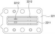
请参考图9,安装板221底面形成有若干相互间隔的条形槽2211,所述负极片211和正极片212的一端分别伸入一条形槽2211内。从而实现负极片211和正极片212一端的间距控制。Referring to FIG. 9 , a plurality of strip-shaped
请参考图6、图7和图8,分隔块213呈近似半圆形,分隔块213侧壁包括底平面和弧面,环形凹槽2131形成在分隔块213的弧面上。为了提高正极片212和负极片211安装的稳定性,可使得环形凹槽2131、条形槽2211的宽度略小于对应的正极片212或负极片211的厚度,形成过盈连接。Please refer to FIG. 6 , FIG. 7 and FIG. 8 , the
负极片211和正极片212的一端形成有电极针2112,安装板221上形成有与电极针2112匹配的针孔2212。若干负极片211的电极针2112位于一侧,若干正极片212的电极针2112位于相对另一侧。Electrode needles 2112 are formed at one end of the
本水解臭氧发生器的防水圈222设于安装板221,防水圈222中部开设供负极片211和正极片212穿过的通槽2221。优选的,防水圈222为硅胶防水圈222。The
安装板221底面形成有定位柱,防水圈222上形成有与定位柱对应的定位孔。安装时,将防水圈222的定位孔对准定位柱,使防水圈222安装在安装板221的底面,再将安装板221和防水圈222通过螺钉拧紧在相应位置,从而完成本装置的安装。A positioning column is formed on the bottom surface of the mounting
上述方案中,正极片212与相邻的负极片211保持一1mm的间隙。即在分隔块213上,相邻的环形凹槽2131之间的间隔为1mm。在安装板221上,相邻的条形槽2211之间的间隔也为1mm。In the above solution, a gap of 1 mm is maintained between the
负极片211和正极片212均为钛电极片。负极片211和正极片212的相对另一端上均形成有两个缺口2111,两个缺口2111相互远离,对应的分隔块213设有两个。彼此远离的两个缺口2111可尽可能提高负极片211和正极片212安装后的稳定性。The
该水解臭氧发生器中,负极片211和正极片212的一端设于安装板221,其相对另一端上形成有缺口2111,通过将分隔块213设于缺口2111处,并使得负极片211和正极片212的另一端伸入分隔块213的环形凹槽2131内,实现负极片211和正极片212的间隔安装。水流入负极片211和正极片212之间的预设间隙被电解产生臭氧。由于此时负极片211和正极片212的另一端的非缺口2111位置是与水接触的,因此提高了与水的接触面积,同时水可自该另一端流入或流出负极片211和正极片212的预设间隙,因此流动性更好。In the hydrolyzed ozone generator, one end of the
本发明公开的灭菌龙头,转动龙头开关50,霍尔开关产生电流信号至PCB板60,同时经净水器过滤的净水自进水口流入通水腔11,水位探针30检测判断是否有水并将检测信息发送至PCB板60,水质探针40获取水质的TDS(溶解性固体总量)信息并发送至PCB板60,若PCB板60获取到霍尔开关的电流信号后,能够同时获取有水且水的TDS≤30的信号,则控制水解臭氧发生器20工作,水解臭氧发生器20产生臭氧对净水进行灭菌消毒,灭菌消毒后的净水自通水腔11的出水口流出。由于出水经过了过滤和臭氧灭菌消毒,因此可直接饮用,且臭氧极易溶于水,臭氧在水中迅速分解为氧气,在杀菌的同时增加水中的氧含量,还能将水质提高,出水标准符合我国GB19298-2014食品安全包装饮用水卫生标准。使用本产品无需更换净水器,降低了更换成本,同时体积小,安装方便。In the sterilization faucet disclosed in the present invention, when the
最后应当说明的是,以上实施例仅用以说明本发明的技术方案,而非对本发明保护范围的限制,尽管参照较佳实施例对本发明作了详细地说明,本领域的普通技术人员应当理解,可以对本发明的技术方案进行修改或者等同替换,而不脱离本发明技术方案的实质和范围。Finally, it should be noted that the above embodiments are only used to illustrate the technical solutions of the present invention, not to limit the protection scope of the present invention. Although the present invention has been described in detail with reference to the preferred embodiments, those of ordinary skill in the art should understand that , the technical solutions of the present invention may be modified or equivalently replaced without departing from the spirit and scope of the technical solutions of the present invention.
Claims (10)
Priority Applications (1)
| Application Number | Priority Date | Filing Date | Title |
|---|---|---|---|
| CN202011028644.3ACN112032332A (en) | 2020-09-25 | 2020-09-25 | Sterilizing tap |
Applications Claiming Priority (1)
| Application Number | Priority Date | Filing Date | Title |
|---|---|---|---|
| CN202011028644.3ACN112032332A (en) | 2020-09-25 | 2020-09-25 | Sterilizing tap |
Publications (1)
| Publication Number | Publication Date |
|---|---|
| CN112032332Atrue CN112032332A (en) | 2020-12-04 |
Family
ID=73575199
Family Applications (1)
| Application Number | Title | Priority Date | Filing Date |
|---|---|---|---|
| CN202011028644.3APendingCN112032332A (en) | 2020-09-25 | 2020-09-25 | Sterilizing tap |
Country Status (1)
| Country | Link |
|---|---|
| CN (1) | CN112032332A (en) |
Cited By (1)
| Publication number | Priority date | Publication date | Assignee | Title |
|---|---|---|---|---|
| CN113896289A (en)* | 2021-09-27 | 2022-01-07 | 厦门英仕卫浴有限公司 | Integrated functional water outlet faucet |
Citations (6)
| Publication number | Priority date | Publication date | Assignee | Title |
|---|---|---|---|---|
| TWM329754U (en)* | 2007-10-08 | 2008-04-01 | Song-Ming Xu | Inspection warning device of water outlet member |
| WO2009156840A2 (en)* | 2008-06-26 | 2009-12-30 | Conequipt Cc | Electronic fluid treatment apparatus and method |
| CN203886676U (en)* | 2014-06-19 | 2014-10-22 | 东莞市沃泰家用电器有限公司 | High-pressure dust-collecting static air cleaning device |
| CN106115863A (en)* | 2015-12-29 | 2016-11-16 | 马金燕 | The preparation facilities of a kind of continuous way life disinfecting water and control method thereof |
| CN106967994A (en)* | 2015-11-12 | 2017-07-21 | 德尔塔阀门公司 | Ozone generators and ozone generator systems for use with water taps |
| CN212360842U (en)* | 2020-09-25 | 2021-01-15 | 深圳欧赛技术有限公司 | Sterilizing tap |
- 2020
- 2020-09-25CNCN202011028644.3Apatent/CN112032332A/enactivePending
Patent Citations (6)
| Publication number | Priority date | Publication date | Assignee | Title |
|---|---|---|---|---|
| TWM329754U (en)* | 2007-10-08 | 2008-04-01 | Song-Ming Xu | Inspection warning device of water outlet member |
| WO2009156840A2 (en)* | 2008-06-26 | 2009-12-30 | Conequipt Cc | Electronic fluid treatment apparatus and method |
| CN203886676U (en)* | 2014-06-19 | 2014-10-22 | 东莞市沃泰家用电器有限公司 | High-pressure dust-collecting static air cleaning device |
| CN106967994A (en)* | 2015-11-12 | 2017-07-21 | 德尔塔阀门公司 | Ozone generators and ozone generator systems for use with water taps |
| CN106115863A (en)* | 2015-12-29 | 2016-11-16 | 马金燕 | The preparation facilities of a kind of continuous way life disinfecting water and control method thereof |
| CN212360842U (en)* | 2020-09-25 | 2021-01-15 | 深圳欧赛技术有限公司 | Sterilizing tap |
Cited By (1)
| Publication number | Priority date | Publication date | Assignee | Title |
|---|---|---|---|---|
| CN113896289A (en)* | 2021-09-27 | 2022-01-07 | 厦门英仕卫浴有限公司 | Integrated functional water outlet faucet |
Similar Documents
| Publication | Publication Date | Title |
|---|---|---|
| JPH0557276A (en) | Water purifier | |
| US10159939B2 (en) | Reverse osmosis system | |
| CN107352685B (en) | Water purification quality guaranteeing system | |
| JP2004520161A (en) | Water treatment system under the sink | |
| CN1500066A (en) | Ozone generator | |
| CN107285550B (en) | Water purification quality guaranteeing system | |
| CN107352686B (en) | Water purification quality guaranteeing system | |
| CA2982268C (en) | Hospital sink and faucet | |
| CN112032332A (en) | Sterilizing tap | |
| CN212360842U (en) | Sterilizing tap | |
| JPH10180259A (en) | Water purifying and sterilizing device | |
| CN107352687B (en) | Water purification quality guaranteeing system | |
| WO2019024802A1 (en) | Water purification quality assurance system | |
| KR100547469B1 (en) | Bidet sterilizer | |
| KR200303777Y1 (en) | A clean water and sterilization device of the seawater | |
| JP3574968B2 (en) | Continuous electrolyzed water generator | |
| KR200301741Y1 (en) | A UV sterilization device with fluid flowing sensor | |
| CN108679267B (en) | Multifunctional electronic faucet | |
| CN210683286U (en) | Water purifier ultraviolet sterilization device with intelligent detection system and water purifier thereof | |
| CN220098641U (en) | Sterilizing water purifying tap and drinking water equipment | |
| KR20020029660A (en) | device for fixed or a breakaway of clean water filter for water ionizing apparatus | |
| JP3605653B2 (en) | Continuous electrolyzed water generator | |
| CN211896481U (en) | Desk type water purifier | |
| KR20120009243A (en) | Water Purifier Filter Assembly with UV Lamp | |
| CN211896143U (en) | High-voltage switch and water purifier with same |
Legal Events
| Date | Code | Title | Description |
|---|---|---|---|
| PB01 | Publication | ||
| PB01 | Publication | ||
| SE01 | Entry into force of request for substantive examination | ||
| SE01 | Entry into force of request for substantive examination | ||
| RJ01 | Rejection of invention patent application after publication | Application publication date:20201204 |