CN112031720A - Device and method for extracting natural gas hydrate by injecting compressed air or nitrogen - Google Patents
Device and method for extracting natural gas hydrate by injecting compressed air or nitrogenDownload PDFInfo
- Publication number
- CN112031720A CN112031720ACN202010533883.8ACN202010533883ACN112031720ACN 112031720 ACN112031720 ACN 112031720ACN 202010533883 ACN202010533883 ACN 202010533883ACN 112031720 ACN112031720 ACN 112031720A
- Authority
- CN
- China
- Prior art keywords
- test kettle
- hydrate
- air
- test
- methane
- Prior art date
- Legal status (The legal status is an assumption and is not a legal conclusion. Google has not performed a legal analysis and makes no representation as to the accuracy of the status listed.)
- Pending
Links
Images


Classifications
- E—FIXED CONSTRUCTIONS
- E21—EARTH OR ROCK DRILLING; MINING
- E21B—EARTH OR ROCK DRILLING; OBTAINING OIL, GAS, WATER, SOLUBLE OR MELTABLE MATERIALS OR A SLURRY OF MINERALS FROM WELLS
- E21B43/00—Methods or apparatus for obtaining oil, gas, water, soluble or meltable materials or a slurry of minerals from wells
- E21B43/16—Enhanced recovery methods for obtaining hydrocarbons
- E21B43/166—Injecting a gaseous medium; Injecting a gaseous medium and a liquid medium
- E21B43/168—Injecting a gaseous medium
Landscapes
- Life Sciences & Earth Sciences (AREA)
- Engineering & Computer Science (AREA)
- Geology (AREA)
- Mining & Mineral Resources (AREA)
- Physics & Mathematics (AREA)
- Environmental & Geological Engineering (AREA)
- Fluid Mechanics (AREA)
- General Life Sciences & Earth Sciences (AREA)
- Geochemistry & Mineralogy (AREA)
- Organic Low-Molecular-Weight Compounds And Preparation Thereof (AREA)
Abstract
Translated fromChinese
Description
Translated fromChinese技术领域technical field
本发明涉及水合物开采技术领域,尤其涉及一种注入压缩空气或氮气开采天然气水合物的装置及方法。The invention relates to the technical field of hydrate exploitation, in particular to a device and method for injecting compressed air or nitrogen to exploit natural gas hydrate.
背景技术Background technique
天然气是所有化石燃料最清洁的燃烧,是减少二氧化碳排放的关键原料。水合物一直是潜在的未来能源,它主要由甲烷和其他天然气的合成物组成,包括甲烷、丙烷、二氧化碳和硫化氢,具体取决于水合物的源气体形成条件,它们在高压和低温条件下是稳定的,因此当任何扰动导致局部平衡时,水合物会分解成成分水和气体;这是常见的水合物回收技术的基础,如减压、热刺激和化学抑制剂注射。气体注入利用注入气体与水合物相之间的化学电位不同,分解水合物。Natural gas is the cleanest burning of all fossil fuels and is a key feedstock for reducing carbon dioxide emissions. Hydrates have been a potential future energy source and are mainly composed of methane and other natural gas compounds, including methane, propane, carbon dioxide, and hydrogen sulfide, depending on the hydrate source gas formation conditions, which are high pressure and low temperature conditions. Stable, so when any perturbation leads to local equilibrium, the hydrate dissociates into its constituent water and gas; this is the basis for common hydrate recovery techniques such as decompression, thermal stimulation, and chemical inhibitor injection. Gas injection utilizes the difference in chemical potential between the injected gas and the hydrate phase to decompose the hydrate.
常见的天然气水合物的开采中常见的开采方法如减压法、热刺激、抑制剂注射以及烟道气替换;首先减压法适用于高孔隙度、高渗透性和高饱和型的带有天然气水合物砂岩,单这种砂岩只占少数部分,无法大面积使用此方法进行开采,且这种方法会产生大量的水份和沙石,使得带有天然气水合物的砂岩变得不稳定,这些不稳定的砂石常常会阻碍持续性的开采;其次,热刺激法主要为盐水喷射、蒸汽喷射原位燃烧,这些方式需要额外消耗大量的能量,且回收的天然气中约50%的能量使用在开采上非常不经济;再如,抑制剂注射法常常采用甲醇、乙醇类进行注射,还需要将这些醇类与水进行分离十分麻烦,且注射抑制剂可能会对海洋生态系统的环境造成严重危害,这种方法基本被认定为不可行的大规模开采天然气水合物的方法;采用烟道气碳替换的方法进行置换甲烷时,其中二氧化碳会优先形成二氧化碳水合物阻塞带有水合物砂石的间隙,降低渗透率。且烟道气的气源源距离注入天然气水合物储层较远,因此需要额外的成本。相比之下,空气是现成的,可以在现场压缩直接注射。Common extraction methods such as decompression method, thermal stimulation, inhibitor injection and flue gas replacement in the exploitation of common natural gas hydrates; first of all, decompression method is suitable for high porosity, high permeability and high saturation type with natural gas Hydrate sandstone, only a small part of this sandstone, cannot be mined by this method in a large area, and this method will produce a large amount of water and sand, making the sandstone with gas hydrates unstable, these Unstable sand and gravel often hinder sustainable mining; secondly, thermal stimulation methods are mainly brine injection and steam injection in-situ combustion, which require a lot of extra energy, and about 50% of the energy in the recovered natural gas is used in Mining is very uneconomical; for another example, the inhibitor injection method often uses methanol and ethanol for injection, and it is very troublesome to separate these alcohols from water, and the injection of inhibitors may cause serious harm to the environment of the marine ecosystem , this method is basically regarded as an unfeasible method for large-scale exploitation of natural gas hydrate; when the method of replacing methane with flue gas is used, carbon dioxide will preferentially form carbon dioxide hydrate to block the gaps with hydrate sand and gravel. , reducing the penetration rate. Moreover, the gas source of the flue gas is far away from the natural gas hydrate reservoir, so additional cost is required. In contrast, air is readily available and can be compressed and injected directly on site.
发明内容SUMMARY OF THE INVENTION
本发明要解决的技术问题是提供一种注入压缩空气或氮气开采天然气水合物的装置及方法,能够为压缩空气开采天然气水合物提供相应的参数支持。The technical problem to be solved by the present invention is to provide a device and method for producing natural gas hydrate by injecting compressed air or nitrogen, which can provide corresponding parameter support for producing natural gas hydrate with compressed air.
为解决上述技术问题,本发明的技术方案为:一种注入压缩空气或氮气开采天然气水合物的装置,其创新点在于:包括测试釜、空气容器、数据采集器、驱动泵、恒温保持器和计算机;In order to solve the above-mentioned technical problems, the technical scheme of the present invention is: a device for injecting compressed air or nitrogen to exploit natural gas hydrate, the innovation of which is that it includes a test kettle, an air container, a data collector, a driving pump, a constant temperature holder and computer;
所述测试釜内设置有一活塞将测试釜体划分为测试区和加压区,且活塞上连接有一活塞管,且该活塞管穿过加压区延伸出测试釜;所述活塞管的一端与测试区导通,活塞管的另一端连接在空气容器上;所述活塞管上设置有位移传感器;所述测试釜的外壁上设置有加热层,且该加热层与恒温保持器相连对测试釜进行加热并保温;所述测试釜内设置有温度传感器,测试釜的两端分别设置有压力传感器;所述驱动泵的一端连接在油箱上,另一端连接在测试釜的加压区,通过油箱内的液压油对活塞进行加压驱动,且驱动泵通过计算机控制驱动;所述空气容器一侧还并联有一甲烷容器;A piston is arranged in the test kettle to divide the test kettle body into a test area and a pressurized area, and a piston tube is connected to the piston, and the piston tube extends out of the test kettle through the pressurized area; one end of the piston tube is connected to the test kettle. The test area is connected, and the other end of the piston tube is connected to the air container; the piston tube is provided with a displacement sensor; the outer wall of the test kettle is provided with a heating layer, and the heating layer is connected with the thermostat to the test kettle Heating and heat preservation are carried out; a temperature sensor is arranged in the test kettle, and pressure sensors are respectively arranged at both ends of the test kettle; one end of the driving pump is connected to the oil tank, and the other end is connected to the pressurized area of the test kettle, The hydraulic oil inside pressurizes and drives the piston, and the drive pump is driven by computer control; a methane container is connected in parallel on one side of the air container;
所述数据采集器与位移传感器、温度传感器、压力传感器相连收集测试过程中的数据,所述数据采集器与计算机相连进行数据分析。The data collector is connected with the displacement sensor, the temperature sensor and the pressure sensor to collect data in the testing process, and the data collector is connected with the computer for data analysis.
一种注入压缩空气或氮气开采天然气水合物的方法:其创新点在于:具体方法如下:A method for exploiting natural gas hydrate by injecting compressed air or nitrogen: its innovative point is: the specific method is as follows:
S1:硅砂岩心的制作:采用直径为260μm-290μm的硅砂将硅沙在373K的烤箱中干燥20小时;将硅砂冷却至室温293K后,在沙中加入预定数量的去离子水,使得硅砂达到水饱和度55%;水饱和的硅砂放入测试釜内,施加3.5 MPa 的推动活塞来压缩混合物且保持测试釜的温度在293K,完成硅砂岩心的制作;S1: Silica sand core production: use silica sand with a diameter of 260μm-290μm to dry the silica sand in a 373K oven for 20 hours; after cooling the silica sand to room temperature 293K, add a predetermined amount of deionized water to the sand to make the silica sand reach The water saturation is 55%; the water-saturated silica sand is put into the test kettle, the push piston of 3.5 MPa is applied to compress the mixture and the temperature of the test kettle is kept at 293K to complete the production of the silica sand core;
S2:水合物的形成:甲烷气体注入测试釜中,并在293 K温度下对系统进行加压;然后,使测试釜的温度保持在293K,达到系统平衡;测试釜温度被设定为273.4K,便完甲烷水合物的形成;甲烷水合物形成完成后,压缩空气注入过量以清除剩余的甲烷气体;测试釜被清除多余的气体混合物,直到测试釜压力比空气和氮水合物分离压力高0.8MPa;S2: Hydrate formation: Methane gas was injected into the test kettle and the system was pressurized at 293 K; then, the temperature of the test kettle was kept at 293 K to reach system equilibrium; the temperature of the test kettle was set at 273.4K , the formation of methane hydrate is completed; after the formation of methane hydrate is completed, excess compressed air is injected to remove the remaining methane gas; the test kettle is cleaned of excess gas mixture until the pressure of the test kettle is 0.8 higher than the separation pressure of air and nitrogen hydrate MPa;
S3:压缩空气或氮气的注入:在恒温恒压下,空气容器通过活塞管向测试釜的测试区内注入空气,且空气的注入梁与前期甲烷的注入量相等,并分阶段减压通过数据采集器实时记录相关数据并通过计算机形成图表。S3: Injection of compressed air or nitrogen: Under constant temperature and pressure, the air container injects air into the test area of the test kettle through the piston tube, and the injection beam of air is equal to the injection amount of methane in the previous stage, and the data is decompressed in stages. The collector records the relevant data in real time and forms a chart through the computer.
本发明的优点在于:The advantages of the present invention are:
1)本发明中采用压缩空气作为气源进行水合物的开采,可以实现解决水合物分解后与空气共存、空气如何影响减压过程问题以及水合物在分解时空气能否被封存的问题;且本发明中压缩空气可以现场直接压缩相比于其余的开采方式,本方案更加环保,更加经济;甲烷的最大浓度为90.5 mol%;相比于采用CO2与氮气的混合气体开采天然气甲烷的回收率达到85%有了较大的提升。1) In the present invention, compressed air is used as the gas source for hydrate extraction, which can solve the problems of coexistence with air after hydrate decomposition, how air affects the decompression process, and whether air can be sealed during hydrate decomposition; and In the present invention, the compressed air can be directly compressed on- site. Compared with other mining methods, this solution is more environmentally friendly and more economical; the maximum concentration of methane is 90.5 mol%; The rate reached 85%, which has greatly improved.
附图说明Description of drawings
下面结合附图和具体实施方式对本发明作进一步详细的说明。The present invention will be described in further detail below with reference to the accompanying drawings and specific embodiments.
图1为本发明的一种注入压缩空气或氮气开采天然气水合物的装置结构图。FIG. 1 is a structural diagram of a device of the present invention for injecting compressed air or nitrogen to exploit natural gas hydrate.
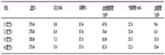
图2为本发明的一种注入压缩空气或氮气开采天然气水合物的方法中测试釜初始参数表。FIG. 2 is a table of initial parameters of the test kettle in a method for exploiting natural gas hydrate by injecting compressed air or nitrogen according to the present invention.
图3为本发明的一种注入压缩空气或氮气开采天然气水合物的方法中不同温度和压力下水合物生成的曲线图。FIG. 3 is a graph showing the formation of hydrates at different temperatures and pressures in a method for producing natural gas hydrates by injecting compressed air or nitrogen according to the present invention.
图4为本发明的一种注入压缩空气或氮气开采天然气水合物的方法中阶梯泄压中甲烷的占比变化图。FIG. 4 is a change diagram of the proportion of methane in the stepped pressure relief in a method for exploiting natural gas hydrate by injecting compressed air or nitrogen according to the present invention.
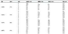
图5为本发明的一种注入压缩空气或氮气开采天然气水合物的多组别试验对比表。FIG. 5 is a comparison table of multi-group experiments of the present invention for the exploitation of natural gas hydrate by injecting compressed air or nitrogen.
图6为本发明的一种注入压缩空气或氮气开采天然气水合物的多组别甲烷回收率对比表。FIG. 6 is a comparison table of multiple groups of methane recovery rates for the exploitation of natural gas hydrate by injecting compressed air or nitrogen according to the present invention.
具体实施方式Detailed ways
为使本发明实施例的目的、技术方案和优点更加清楚,下面将结合本发明实施例中的附图,对本发明实施例中的技术方案进行清楚、完整地描述,显然,所描述的实施例是本发明一部分实施例,而不是全部的实施例。通常在此处附图中描述和示出的本发明实施例的组件可以以各种不同的配置来布置和设计。In order to make the purposes, technical solutions and advantages of the embodiments of the present invention clearer, the technical solutions in the embodiments of the present invention will be clearly and completely described below with reference to the accompanying drawings in the embodiments of the present invention. Obviously, the described embodiments These are some embodiments of the present invention, but not all embodiments. The components of the embodiments of the invention generally described and illustrated in the drawings herein may be arranged and designed in a variety of different configurations.
因此,以下对在附图中提供的本发明的实施例的详细描述并非旨在限制要求保护的本发明的范围,而是仅仅表示本发明的选定实施例。基于本发明中的实施例,本领域普通技术人员在没有作出创造性劳动前提下所获得的所有其他实施例,都属于本发明保护的范围。Thus, the following detailed description of the embodiments of the invention provided in the accompanying drawings is not intended to limit the scope of the invention as claimed, but is merely representative of selected embodiments of the invention. Based on the embodiments of the present invention, all other embodiments obtained by those of ordinary skill in the art without creative efforts shall fall within the protection scope of the present invention.
应注意到:相似的标号和字母在下面的附图中表示类似项,因此,一旦某一项在一个附图中被定义,则在随后的附图中不需要对其进行进一步定义和解释。It should be noted that like numerals and letters refer to like items in the following figures, so once an item is defined in one figure, it does not require further definition and explanation in subsequent figures.
在本发明的描述中,需要说明的是,术语“中心”、“上”、“下”、“左”、“右”、“竖直”、“水平”、“内”、“外”等指示的方位或位置关系为基于附图所示的方位或位置关系,或者是该发明产品使用时惯常摆放的方位或位置关系,仅是为了便于描述本发明和简化描述,而不是指示或暗示所指的装置或元件必须具有特定的方位、以特定的方位构造和操作,因此不能理解为对本发明的限制。此外,术语“第一”、“第二”、“第三”等仅用于区分描述,而不能理解为指示或暗示相对重要性。 In the description of the present invention, it should be noted that the terms "center", "upper", "lower", "left", "right", "vertical", "horizontal", "inner", "outer", etc. The indicated orientation or positional relationship is based on the orientation or positional relationship shown in the accompanying drawings, or the orientation or positional relationship that the product of the invention is usually placed in use, only for the convenience of describing the present invention and simplifying the description, rather than indicating or implying The device or element referred to must have a particular orientation, be constructed and operate in a particular orientation, and therefore should not be construed as limiting the invention. Furthermore, the terms "first", "second", "third", etc. are only used to differentiate the description and should not be construed as indicating or implying relative importance.
此外,术语“水平”、“竖直”等术语并不表示要求部件绝对水平或悬垂,而是可以稍微倾斜。如“水平”仅仅是指其方向相对“竖直”而言更加水平,并不是表示该结构一定要完全水平,而是可以稍微倾斜。Furthermore, the terms "horizontal", "vertical" and the like do not imply that a component is required to be absolutely horizontal or overhang, but rather may be slightly inclined. For example, "horizontal" only means that its direction is more horizontal than "vertical", it does not mean that the structure must be completely horizontal, but can be slightly inclined.
在本发明的描述中,还需要说明的是,除非另有明确的规定和限定,术语“设置”、“安装”、“相连”、“连接”应做广义理解,例如,可以是固定连接,也可以是可拆卸连接,或一体地连接;可以是机械连接,也可以是电连接;可以是直接相连,也可以通过中间媒介间接相连,可以是两个元件内部的连通。对于本领域的普通技术人员而言,可以具体情况理解上述术语在本发明中的具体含义。In the description of the present invention, it should also be noted that, unless otherwise expressly specified and limited, the terms "arranged", "installed", "connected" and "connected" should be understood in a broad sense, for example, it may be a fixed connection, It can also be a detachable connection, or an integral connection; it can be a mechanical connection or an electrical connection; it can be a direct connection, or an indirect connection through an intermediate medium, or the internal communication between the two components. For those of ordinary skill in the art, the specific meanings of the above terms in the present invention can be understood in specific situations.
如图1至图6所示的一种注入压缩空气或氮气开采天然气水合物的装置,包括测试釜1、空气容器2、数据采集器3、驱动泵4、恒温保持器5和计算机6。As shown in Figures 1 to 6, a device for injecting compressed air or nitrogen to exploit natural gas hydrate includes a
测试釜1内设置有一活塞11将测试釜体划分为测试区和加压区,且活塞11上连接有一活塞管12,且该活塞管12穿过加压区延伸出测试釜;活塞管12的一端与测试区导通,活塞管12的另一端连接在空气容器2上;活塞管12上设置有位移传感器7;测试釜1的外壁上设置有加热层,且该加热层与恒温保持器5相连对测试釜1进行加热并保温;测试釜1内设置有温度传感器13,测试釜1的两端分别设置有压力传感器14;驱动泵4的一端连接在油箱上,另一端连接在测试釜1的加压区,通过油箱内的液压油对活塞进行加压驱动,且驱动泵通过计算机控制驱动;空气容器2一侧还并联有一甲烷容器8;A piston 11 is provided in the
数据采集器3与位移传感器7、温度传感器13、压力传感器14相连收集测试过程中的数据,数据采集器3与计算机6相连进行数据分析。The
一种注入压缩空气或氮气开采天然气水合物的方法:具体方法如下:A method for exploiting natural gas hydrate by injecting compressed air or nitrogen: the specific method is as follows:
S1:硅砂岩心的制作:采用直径为260μm-290μm的硅砂将硅沙在373K的烤箱中干燥20小时;将硅砂冷却至室温293K后,在沙中加入预定数量的去离子水,使得硅砂达到水饱和度55%;水饱和的硅砂放入测试釜内,施加3.5 MPa 的推动活塞来压缩混合物且保持测试釜的温度在293K,完成硅砂岩心的制作;S1: Silica sand core production: use silica sand with a diameter of 260μm-290μm to dry the silica sand in an oven at 373K for 20 hours; after cooling the silica sand to room temperature 293K, add a predetermined amount of deionized water to the sand to make the silica sand reach The water saturation is 55%; the water-saturated silica sand is put into the test kettle, the push piston of 3.5 MPa is applied to compress the mixture and the temperature of the test kettle is kept at 293K to complete the production of the silica sand core;
S2:水合物的形成:甲烷气体注入测试釜中,并在293 K温度下对系统进行加压;然后,使测试釜的温度保持在293K,达到系统平衡;测试釜温度被设定为273.4K,便完甲烷水合物的形成;甲烷水合物形成完成后,压缩空气注入过量以清除剩余的甲烷气体;测试釜被清除多余的气体混合物,直到测试釜压力比空气和氮水合物分离压力高0.8MPa;S2: Hydrate formation: Methane gas was injected into the test kettle and the system was pressurized at 293 K; then, the temperature of the test kettle was kept at 293 K to reach system equilibrium; the temperature of the test kettle was set at 273.4K , the formation of methane hydrate is completed; after the formation of methane hydrate is completed, excess compressed air is injected to remove the remaining methane gas; the test kettle is cleaned of excess gas mixture until the pressure of the test kettle is 0.8 higher than the separation pressure of air and nitrogen hydrate MPa;
S3:压缩空气或氮气的注入:在恒温恒压下,空气容器通过活塞管向测试釜的测试区内注入空气,且空气的注入梁与前期甲烷的注入量相等,并分阶段减压通过数据采集器实时记录相关数据并通过计算机形成图表。S3: Injection of compressed air or nitrogen: Under constant temperature and pressure, the air container injects air into the test area of the test kettle through the piston tube, and the injection beam of air is equal to the injection amount of methane in the previous stage, and the data is decompressed in stages. The collector records the relevant data in real time and forms a chart through the computer.
由图4可以看出一旦系统压力下降到空气-水合物相边界以下,在实验温度下,甲烷水合物立即开始分解,这种即时分解能够在空气/氮存在的情况下实现多阶段减压,空气/氮注入后甲烷水合物在每个阶段快速分解,这表现在曲线的几乎垂直部分,随后是缓慢的分解,随着系统达到新的热力学平衡,它最终会随着时间而停止。It can be seen from Fig. 4 that once the system pressure drops below the air-hydrate phase boundary, at the experimental temperature, methane hydrate immediately begins to decompose. This instant decomposition can achieve multi-stage decompression in the presence of air/nitrogen, The rapid decomposition of methane hydrate at each stage after air/nitrogen injection is manifested in the nearly vertical part of the curve, followed by a slow decomposition that eventually stops over time as the system reaches a new thermodynamic equilibrium.
由图5可以看出甲烷水合物分解是通过从甲烷贫瘠区域注入的气体向甲烷富集区注入的均衡相位边界转移实现的;实验在每个压力阶段达到的初始压力、设定压力、达到平衡时的压力和气相甲烷浓度;在每个实验的第5阶段结束时,系统被设定为目标气相甲烷浓度的压力,并留出足够的时间在之后达到平衡,气相甲烷浓度为60.3 mol%、56.5 mol%、55.3 mol%和58.5 mol%。It can be seen from Fig. 5 that the decomposition of methane hydrate is achieved by the equilibrium phase boundary transfer from the gas injected from the methane-poor area to the methane-rich area; the initial pressure, set pressure, and equilibrium reached in each pressure stage of the experiment pressure and gas-phase methane concentration at the time of the experiment; at the end of
由图6可以看出在多阶段减压的第一阶段,水合物阶段释放到气相的甲烷量从实验1的0.10 mol增加到0.41 mol,实验2为0.15~0.85 mol,实验3为0.29~0.84 mol,实验为0.12~0.64 mol; 实验4.回收率分别为38.0%、64.4%、96.9%和67.9%。尽管实验1(60.3mol%)的气相甲烷浓度在实验阶段1结束时略高,比在实验2(56.5 mol%),实验3(55.3mol%)和实验(58.5 mol%)随着温度的升高,甲烷的回收量增加归因于水合物平衡压力;在较高温度下,水合物平衡压力较高,这意味着与水合物相平衡的气相密度较高;因此,要达到给定的蒸汽相甲烷浓度,需要在更高的温度下从水合物中释放更多的甲烷,而不是在较低温度下释放的。It can be seen from Fig. 6 that in the first stage of multi-stage decompression, the amount of methane released into the gas phase in the hydrate stage increased from 0.10 mol in
实验结果表明,在气相中甲烷浓度不同,可以分多个阶段进行减压,空气和氮气的吸收通过改变甲烷水合物稳定区,实现甲烷水合物快速分离;动力学研究表明,气相甲烷浓度在每个阶段的短时间间隔内迅速上升,空气和氮气注入增强了减压过程,在甲烷水合物分离压力以上的压力下产生甲烷含量超过80mol%的气体;在注入气体存在高温下,甲烷回收率越高,表明高温有利于甲烷回收的动力学和热力学;在类似条件下,氮注入表明,通过空气喷射,甲烷回收率有所提高;该技术可大大提高常规减压法从天然气水合物储层中回收甲烷的技术可行性和经济可行性。The experimental results show that the methane concentration in the gas phase is different, and the decompression can be carried out in multiple stages. The absorption of air and nitrogen can change the methane hydrate stable zone to achieve rapid separation of methane hydrate; kinetic studies show that the gas phase methane concentration is A rapid rise in a short time interval of each stage, the injection of air and nitrogen enhances the decompression process, producing a gas with a methane content of more than 80 mol% at a pressure above the separation pressure of methane hydrate; in the presence of high temperature in the injected gas, the higher the methane recovery rate high, indicating that high temperature favors the kinetics and thermodynamics of methane recovery; under similar conditions, nitrogen injection shows that methane recovery is improved by air injection; this technique can greatly improve conventional decompression methods from natural gas hydrate reservoirs Technical feasibility and economic feasibility of recovering methane.
本行业的技术人员应该了解,本发明不受上述实施例的限制,上述实施例和说明书中描述的只是说明本发明的原理,在不脱离本发明精神和范围的前提下,本发明还会有各种变化和改进,这些变化和改进都落入要求保护的本发明范围内。本发明要求保护范围由所附的权利要求书及其等效物界定。Those skilled in the art should understand that the present invention is not limited by the above-mentioned embodiments, and the descriptions in the above-mentioned embodiments and the description are only to illustrate the principle of the present invention. Without departing from the spirit and scope of the present invention, the present invention will have Various changes and modifications fall within the scope of the claimed invention. The claimed scope of the present invention is defined by the appended claims and their equivalents.
Claims (2)
Translated fromChinesePriority Applications (1)
| Application Number | Priority Date | Filing Date | Title |
|---|---|---|---|
| CN202010533883.8ACN112031720A (en) | 2020-06-12 | 2020-06-12 | Device and method for extracting natural gas hydrate by injecting compressed air or nitrogen |
Applications Claiming Priority (1)
| Application Number | Priority Date | Filing Date | Title |
|---|---|---|---|
| CN202010533883.8ACN112031720A (en) | 2020-06-12 | 2020-06-12 | Device and method for extracting natural gas hydrate by injecting compressed air or nitrogen |
Publications (1)
| Publication Number | Publication Date |
|---|---|
| CN112031720Atrue CN112031720A (en) | 2020-12-04 |
Family
ID=73579459
Family Applications (1)
| Application Number | Title | Priority Date | Filing Date |
|---|---|---|---|
| CN202010533883.8APendingCN112031720A (en) | 2020-06-12 | 2020-06-12 | Device and method for extracting natural gas hydrate by injecting compressed air or nitrogen |
Country Status (1)
| Country | Link |
|---|---|
| CN (1) | CN112031720A (en) |
Cited By (4)
| Publication number | Priority date | Publication date | Assignee | Title |
|---|---|---|---|---|
| CN113027446A (en)* | 2021-03-30 | 2021-06-25 | 中国石油大学(华东) | Auxiliary device for oxygen reduction air drive |
| CN113204050A (en)* | 2021-04-27 | 2021-08-03 | 青岛海洋地质研究所 | Method for preparing hydrate reservoirs with different burial depths |
| CN114278274A (en)* | 2021-12-28 | 2022-04-05 | 中国地质大学(北京) | Natural gas hydrate exploitation simulation device and method |
| CN116241221A (en)* | 2023-02-24 | 2023-06-09 | 中国石油大学(北京) | A method for mining natural gas hydrate and sequestering carbon dioxide |
Citations (5)
| Publication number | Priority date | Publication date | Assignee | Title |
|---|---|---|---|---|
| WO2014046343A1 (en)* | 2012-09-20 | 2014-03-27 | 한국과학기술원 | Method of producing methane gas from gas hydrate by injecting gas |
| US20150107826A1 (en)* | 2013-10-22 | 2015-04-23 | Korea Advanced Institute Of Science And Technology | Method for Recovering Methane Gas from Natural Gas Hydrate by Injecting CO2 and Air Mixed Gas |
| CN105259003A (en)* | 2015-11-25 | 2016-01-20 | 中国科学院广州能源研究所 | Experiment device and method for synthesizing marine natural gas hydrate sample |
| CN110630228A (en)* | 2019-09-23 | 2019-12-31 | 中国地质大学(武汉) | Apparatus and method for evaluating wellbore sand production and sand control in CO2/N2 replacement method for hydrate production |
| CN110939411A (en)* | 2019-11-11 | 2020-03-31 | 华南理工大学 | Supercritical CO2Replacement mining of CH4Hydrate experimental device and using method |
- 2020
- 2020-06-12CNCN202010533883.8Apatent/CN112031720A/enactivePending
Patent Citations (5)
| Publication number | Priority date | Publication date | Assignee | Title |
|---|---|---|---|---|
| WO2014046343A1 (en)* | 2012-09-20 | 2014-03-27 | 한국과학기술원 | Method of producing methane gas from gas hydrate by injecting gas |
| US20150107826A1 (en)* | 2013-10-22 | 2015-04-23 | Korea Advanced Institute Of Science And Technology | Method for Recovering Methane Gas from Natural Gas Hydrate by Injecting CO2 and Air Mixed Gas |
| CN105259003A (en)* | 2015-11-25 | 2016-01-20 | 中国科学院广州能源研究所 | Experiment device and method for synthesizing marine natural gas hydrate sample |
| CN110630228A (en)* | 2019-09-23 | 2019-12-31 | 中国地质大学(武汉) | Apparatus and method for evaluating wellbore sand production and sand control in CO2/N2 replacement method for hydrate production |
| CN110939411A (en)* | 2019-11-11 | 2020-03-31 | 华南理工大学 | Supercritical CO2Replacement mining of CH4Hydrate experimental device and using method |
Non-Patent Citations (3)
| Title |
|---|
| 宁伏龙等: "天然气水合物开采储层出砂研究进展与思考", 《地质科技通报》* |
| 李守定等: "天然气水合物开采方法及海域试采分析", 《工程地质学报》* |
| 李淑霞等: "神狐水合物藏降压开采分解前缘数值模拟研究", 《中国科学:物理学 力学 天文学》* |
Cited By (5)
| Publication number | Priority date | Publication date | Assignee | Title |
|---|---|---|---|---|
| CN113027446A (en)* | 2021-03-30 | 2021-06-25 | 中国石油大学(华东) | Auxiliary device for oxygen reduction air drive |
| CN113204050A (en)* | 2021-04-27 | 2021-08-03 | 青岛海洋地质研究所 | Method for preparing hydrate reservoirs with different burial depths |
| CN113204050B (en)* | 2021-04-27 | 2022-03-22 | 青岛海洋地质研究所 | Preparation methods of hydrate reservoirs at different buried depths |
| CN114278274A (en)* | 2021-12-28 | 2022-04-05 | 中国地质大学(北京) | Natural gas hydrate exploitation simulation device and method |
| CN116241221A (en)* | 2023-02-24 | 2023-06-09 | 中国石油大学(北京) | A method for mining natural gas hydrate and sequestering carbon dioxide |
Similar Documents
| Publication | Publication Date | Title |
|---|---|---|
| CN112031720A (en) | Device and method for extracting natural gas hydrate by injecting compressed air or nitrogen | |
| Gao et al. | Tuning the fluid production behaviour of hydrate-bearing sediments by multi-stage depressurization | |
| US8763697B2 (en) | Process for generating hydrogen | |
| US5402847A (en) | Coal bed methane recovery | |
| CA2537708C (en) | Method for natural gas production | |
| RU2370642C2 (en) | Gas recovery by conversion of gas hydrate | |
| US20030000711A1 (en) | Combined steam and vapor extraction process (SAVEX) for in situ bitumen and heavy oil production | |
| CN111878044A (en) | Device and method for simulating exploitation of hydrate by injecting flue gas | |
| CN105545273A (en) | A device and method for CO2 fracturing displacement production of natural gas hydrate in land area | |
| US8672027B2 (en) | In situ fluid reservoir stimulation process | |
| CN110159232A (en) | A kind of exploitation sea bed gas hydrate device and method | |
| WO2014205163A1 (en) | Process for enhanced oil recovery using capture of carbon dioxide | |
| US20150344770A1 (en) | System and method for producing carbon dioxide for use in hydrocarbon recovery | |
| CN107269254A (en) | A kind of well group structures and methods using ground die mould geothermal energy extracting hydrate on bottom of sea | |
| Shen et al. | Numerical investigation of fracturing fluid invasion into hydrate reservoirs during hydraulic-fracturing stimulation | |
| US20130036748A1 (en) | System and method for producing carbon dioxide for use in hydrocarbon recovery | |
| CN108252692A (en) | A kind of method that shale oil recovery is improved using air oxidation thermal fracture | |
| EA018879B1 (en) | Producing gaseous hydrocarbons from hydrate capped reservoirs | |
| US8991491B2 (en) | Increasing enhanced oil recovery value from waste gas | |
| WO2023068971A1 (en) | Method of enhancing recovery from heavy oil and bitumen reservoirs | |
| JP3276407B2 (en) | How to collect underground hydrocarbon hydrates | |
| US12264564B1 (en) | In-situ process to produce hydrogen-bearing gas from underground petroleum reservoirs | |
| US4046195A (en) | Thermal recovery of hydrocarbons from tar sands | |
| WO2025111007A1 (en) | In-situ process to produce hydrogen-bearing gas from underground petroleum reservoirs | |
| Solomon | Investigation of production of dimethyl ether (dme) from renewable resources and its integration into the oil production system |
Legal Events
| Date | Code | Title | Description |
|---|---|---|---|
| PB01 | Publication | ||
| PB01 | Publication | ||
| SE01 | Entry into force of request for substantive examination | ||
| SE01 | Entry into force of request for substantive examination | ||
| RJ01 | Rejection of invention patent application after publication | Application publication date:20201204 | |
| RJ01 | Rejection of invention patent application after publication |