CN112030977A - Side wall grouting construction method and device for easy-collapse stratum drilling retaining wall - Google Patents
Side wall grouting construction method and device for easy-collapse stratum drilling retaining wallDownload PDFInfo
- Publication number
- CN112030977A CN112030977ACN202011048537.7ACN202011048537ACN112030977ACN 112030977 ACN112030977 ACN 112030977ACN 202011048537 ACN202011048537 ACN 202011048537ACN 112030977 ACN112030977 ACN 112030977A
- Authority
- CN
- China
- Prior art keywords
- grouting
- wall
- airbag
- inner cylinder
- pipe
- Prior art date
- Legal status (The legal status is an assumption and is not a legal conclusion. Google has not performed a legal analysis and makes no representation as to the accuracy of the status listed.)
- Pending
Links
Images


Classifications
- E—FIXED CONSTRUCTIONS
- E02—HYDRAULIC ENGINEERING; FOUNDATIONS; SOIL SHIFTING
- E02D—FOUNDATIONS; EXCAVATIONS; EMBANKMENTS; UNDERGROUND OR UNDERWATER STRUCTURES
- E02D15/00—Handling building or like materials for hydraulic engineering or foundations
- E02D15/02—Handling of bulk concrete specially for foundation or hydraulic engineering purposes
- E02D15/04—Placing concrete in mould-pipes, pile tubes, bore-holes or narrow shafts
Landscapes
- Engineering & Computer Science (AREA)
- General Engineering & Computer Science (AREA)
- Structural Engineering (AREA)
- Life Sciences & Earth Sciences (AREA)
- General Life Sciences & Earth Sciences (AREA)
- Mining & Mineral Resources (AREA)
- Paleontology (AREA)
- Civil Engineering (AREA)
- Bulkheads Adapted To Foundation Construction (AREA)
Abstract
Description
Translated fromChinese技术领域technical field
本发明涉及桩孔施工设备技术领域,具体涉及一种用于易坍塌地层钻孔护壁的侧壁注浆工法和装置。The invention relates to the technical field of pile hole construction equipment, in particular to a sidewall grouting method and device used for the wall protection of boreholes in easily collapsed strata.
背景技术Background technique
桩基础是房屋及桥梁结构最常见的基础形式,其成孔方式主要有冲击钻成孔以及旋挖钻成孔,并采用泥浆护壁,桩基穿过的地层复杂多样,当穿过如粉细砂地层、砂卵石地层等特殊地层时,由于地层的强透水性和低粘聚性,传统的泥浆护壁容易失效,从而引起孔壁坍塌,进而对桩基施工的质量、安全、进度产生较严重影响。Pile foundation is the most common foundation form of house and bridge structure. Its hole forming methods mainly include impact drilling and rotary drilling, and mud wall protection is used. The stratum that the pile foundation passes through is complex and diverse. In special strata such as sandy stratum and sandy pebble stratum, due to the strong water permeability and low cohesion of the stratum, the traditional mud retaining wall is easy to fail, causing the hole wall to collapse, which will seriously affect the quality, safety and progress of the pile foundation construction. influences.
传统的改进方法有跟管钻进,地面预注浆处理等方法,其中地面预注浆处理方法需要设计单位超前设计,投资加大;而跟管钻进需投入较多的钢护筒,钢材投入较大,成本较高。The traditional improvement methods include pipe drilling and ground pre-grouting treatment. Among them, the ground pre-grouting treatment method requires the design unit to design in advance and increase the investment; while the pipe drilling requires more investment in steel casings and steel casings. The investment is large and the cost is high.
发明内容SUMMARY OF THE INVENTION
本发明的目的在于提供一种用于易坍塌地层钻孔护壁的侧壁注浆工法和装置,解决传统的方法对孔壁坍塌的预防存在投资较大、成本较高的问题。The purpose of the present invention is to provide a sidewall grouting method and device for the wall of a borehole in an easily collapsed stratum, so as to solve the problems of large investment and high cost in preventing the collapse of the hole wall by the traditional method.
为解决上述的技术问题,本发明采用的第一种技术方案是:In order to solve the above-mentioned technical problem, the first technical scheme adopted by the present invention is:
一种用于易坍塌地层钻孔护壁的侧壁注浆装置,包括内圆筒,沿所述内圆筒的外壁从上至下依次设置有上密封气囊、注浆气囊和下密封气囊,所述内圆筒内竖向设有注浆管、第一充放气管、第二充放气管和第三充放气管,所述注浆管依次贯穿内圆筒和注浆气囊,并在注浆气囊的外壁形成出浆液孔,所述第一充放气管、第二充放气管和第三充放气管分别与上密封气囊、注浆气囊和下密封气囊相连通。A side wall grouting device used for a wall of a borehole in an easily collapsed stratum, comprising an inner cylinder, an upper sealing airbag, a grouting airbag and a lower sealing airbag are sequentially arranged along the outer wall of the inner cylinder from top to bottom. The inner cylinder is vertically provided with a grouting pipe, a first filling and discharging pipe, a second filling and discharging pipe, and a third filling and discharging pipe. A slurry hole is formed on the outer wall of the airbag, and the first inflation and deflation pipe, the second inflation and deflation pipe and the third inflation and deflation pipe are respectively communicated with the upper sealing airbag, the grouting airbag and the lower sealing airbag.
进一步的技术方案是,所述内圆筒内竖向设有中央杆,所述中央杆的上端穿出内圆筒并置于内圆筒的上方,所述中央杆的外壁通过连接板与内圆筒的内壁相连。A further technical solution is that a central rod is vertically arranged in the inner cylinder, the upper end of the central rod penetrates the inner cylinder and is placed above the inner cylinder, and the outer wall of the central rod is connected to the inner cylinder through a connecting plate. The inner walls of the cylinder are connected.
更进一步的技术方案是,所述连接板设置为两个以上,两个以上的连接板沿内圆筒的径向均匀设置形成连接架,所述连接架设置为两个以上并且沿内圆筒的轴向均匀设置。A further technical solution is that there are more than two connecting plates, and the two or more connecting plates are evenly arranged along the radial direction of the inner cylinder to form a connecting frame, and the connecting frames are arranged at more than two and are arranged along the inner cylinder. The axial direction is evenly set.
更进一步的技术方案是,所述连接架使中央杆与内圆筒之间留设有多个连接间隙,所述第一充放气管、第二充放气管和第三充放气管分别通过各个连接间隙延伸至内圆筒的上方。A further technical solution is that the connecting frame leaves a plurality of connection gaps between the central rod and the inner cylinder, and the first inflating and deflating pipes, the second inflating and deflating pipes and the third inflating and deflating pipes pass through each of them respectively. The connection gap extends above the inner cylinder.
更进一步的技术方案是,所述内圆筒的外壁从上至下依次设有均呈圆环形的上盖板、上隔板、下隔板和下盖板;A further technical solution is that the outer wall of the inner cylinder is sequentially provided with an upper cover plate, an upper partition plate, a lower partition plate and a lower cover plate, all of which are annular in shape from top to bottom;
所述上盖板和上隔板之间形成上密封仓,所述上密封气囊设置于上密封仓内,且上密封气囊的上下两侧分别与上盖板和上隔板相贴,上密封气囊的内侧与内圆筒的外壁相贴;An upper sealing chamber is formed between the upper cover plate and the upper partition plate, the upper sealing air bag is arranged in the upper sealing chamber, and the upper and lower sides of the upper sealing air bag are respectively attached to the upper cover plate and the upper partition plate, and the upper sealing chamber is The inner side of the air bag is in contact with the outer wall of the inner cylinder;
所述上隔板和下隔板之间形成中注浆仓,所述注浆气囊设置于中注浆仓内,且注浆气囊的上下两侧分别与上隔板和下隔板相贴,注浆气囊的内侧与内圆筒的外壁相贴;A middle grouting silo is formed between the upper baffle and the lower baffle, the grouting airbag is arranged in the middle grouting silo, and the upper and lower sides of the grouting airbag are respectively attached to the upper baffle and the lower baffle, The inner side of the grouting air bag is in contact with the outer wall of the inner cylinder;
所述下隔板和下盖板之间形成下密封仓,所述下密封气囊设置于下密封仓内,且下密封气囊的上下两侧分别与下隔板和下盖板相贴,下密封气囊内侧与内圆筒的外壁相贴。A lower sealing chamber is formed between the lower partition and the lower cover, the lower sealing airbag is arranged in the lower sealing chamber, and the upper and lower sides of the lower sealing airbag are respectively attached to the lower partition and the lower cover, and the lower sealing The inner side of the airbag is in contact with the outer wall of the inner cylinder.
更进一步的技术方案是,所述中注浆仓内设有两个以上的竖隔板,所述竖隔板的上下两端分别与上隔板和下隔板相连,所述竖隔板的内侧与内圆筒相连,所述竖隔板将中注浆仓分隔为两个以上的放置仓,所述注浆气囊设置为两个以上并且分别位于各个放置仓内;A further technical solution is that there are more than two vertical partitions in the middle grouting bin, the upper and lower ends of the vertical partitions are respectively connected with the upper partition and the lower partition, and the vertical partitions are The inner side is connected with the inner cylinder, the vertical partition divides the middle grouting bin into two or more placement bins, and the grouting airbags are set to more than two and are respectively located in each placement bin;
所述竖隔板内横向设有注浆液通道,所述注浆液通道的一端在竖隔板的外侧形成所述出浆液孔,另一端在内圆筒的内壁形成连接孔,并与所述注浆管相连通。The vertical partition plate is provided with a grouting liquid channel laterally, one end of the grouting liquid channel forms the slurry outlet hole on the outer side of the vertical partition plate, and the other end forms a connecting hole on the inner wall of the inner cylinder, and is connected with the The grouting pipe is connected.
本发明采用的第二种技术方案是:The second technical scheme adopted by the present invention is:
一种用于易坍塌地层钻孔护壁的侧壁注浆装置的注浆工法,包括如下步骤:A grouting method for a side wall grouting device for a borehole wall in an easily collapsed formation, comprising the following steps:
S1、利用钻孔装置在地层钻出桩孔,将注浆装置放置于桩孔中;S1. Use the drilling device to drill the pile hole in the stratum, and place the grouting device in the pile hole;
S2、利用第一充放气管和第三充放气管对上密封气囊和下密封气囊进行充气,使上密封气囊和下密封气囊与桩孔的内壁紧贴,形成密封;S2, use the first inflation and deflation pipe and the third inflation and deflation pipe to inflate the upper sealing airbag and the lower sealing airbag, so that the upper sealing airbag and the lower sealing airbag are closely attached to the inner wall of the pile hole to form a seal;
S3、打开注浆管,将浆液沿注浆管和出浆液孔注入到注浆气囊与桩孔内壁的空隙中,然后关闭注浆管;S3. Open the grouting pipe, inject the grout into the gap between the grouting airbag and the inner wall of the pile hole along the grouting pipe and the grout outlet hole, and then close the grouting pipe;
S4、利用第二充放气管对注浆气囊进行充气,使注浆气囊与桩孔的内壁紧贴,以使浆液在压力作用下渗入桩孔周边地层;S4. Inflate the grouting air bag with the second inflation and deflation pipe, so that the grouting air bag is in close contact with the inner wall of the pile hole, so that the slurry can penetrate into the surrounding stratum of the pile hole under the action of pressure;
S5、利用第二充放气管对注浆气囊进行放气;S5, use the second inflation and deflation pipe to deflate the grouting airbag;
S6、多次重复前述S3-S5步骤;S6, repeat the aforementioned steps S3-S5 for many times;
S7、打开注浆管并注入清水对注浆管进行清洗;S7, open the grouting pipe and inject clean water to clean the grouting pipe;
S8、待初凝时间达到后,利用第一充放气管和第三充放气管对上密封气囊和下密封气囊进行放气,然后将将注浆装置从桩孔内取出。S8. After the initial setting time is reached, use the first inflation and deflation pipe and the third inflation and deflation pipe to deflate the upper sealing airbag and the lower sealing airbag, and then take out the grouting device from the pile hole.
更进一步的技术方案是,当易坍塌地层厚度小于等于2m时,在钻孔穿透该层0.5-1m时注浆,一次完成;A further technical solution is that when the thickness of the stratum that is prone to collapse is less than or equal to 2m, grouting is performed when the drill hole penetrates 0.5-1m of the layer, and it is completed at one time;
当易坍塌地层厚度超过2m时,分段多次注浆。When the thickness of the slump-prone formation exceeds 2m, the grouting shall be performed in stages for multiple times.
更进一步的技术方案是,所述分段多次注浆的方法为:自进入该易坍塌地层2.5m,第一次注浆,固化后钻进,每钻进2m,侧壁注浆一次,钻进、注浆交替进行,直至穿透易坍塌地层。A further technical solution is that the method of multi-stage grouting is as follows: grouting for the first time after entering the easily collapsed stratum for 2.5m, drilling after solidification, and grouting the side wall once every 2m of drilling, Drilling and grouting are carried out alternately until the stratum that is prone to collapse is penetrated.
更进一步的技术方案是,所述浆液采用掺入外加剂和膨润土的水泥浆,或水泥水玻璃双液浆;A further technical solution is that the slurry adopts cement slurry mixed with admixture and bentonite, or cement-water glass double-liquid slurry;
所述浆液的初凝时间10-15min,终注压力0.5MPa。The initial setting time of the slurry is 10-15min, and the final injection pressure is 0.5MPa.
与现有技术相比,本发明的有益效果是:在钻孔完成后将注浆装置放置于桩孔内,利用第一充放气管和第三充放气管对上密封气囊和下密封气囊进行充气,使上密封气囊和下密封气囊与桩孔的内壁紧贴,形成密封,以对注浆装置的位置进行固定,然后打开注浆管,将浆液沿注浆管和出浆液孔注入到注浆气囊与桩孔内壁的空隙中,然后关闭注浆管,利用第二充放气管对注浆气囊进行充气,使注浆气囊与桩孔的内壁紧贴,以使浆液在压力作用下渗入桩孔周边地层,利用易坍塌地层的透水性,将注浆浆液从侧壁向周边注入,扩散到井壁周边一定范围内并固化,形成护壁结构,本注浆装置具有操作简单,材料投入少等优点,利用本注浆装置的施工工法形成施工护壁,具有施工速度快的优势。Compared with the prior art, the beneficial effect of the present invention is: after the drilling is completed, the grouting device is placed in the pile hole, and the upper sealing airbag and the lower sealing airbag are carried out using the first inflation and deflation pipe and the third inflation and deflation pipe. Inflate, make the upper sealing airbag and the lower sealing airbag close to the inner wall of the pile hole to form a seal to fix the position of the grouting device, then open the grouting pipe, and inject the grouting along the grouting pipe and the grouting hole. In the gap between the grouting air bag and the inner wall of the pile hole, then close the grouting pipe, and inflate the grouting air bag with the second inflation and release pipe, so that the grouting air bag is close to the inner wall of the pile hole, so that the slurry can penetrate into the pile under the action of pressure. For the stratum around the hole, the grouting slurry is injected from the side wall to the periphery by using the water permeability of the easily collapsed stratum, diffused to a certain range around the well wall and solidified to form a retaining wall structure. The grouting device has the advantages of simple operation and less material input, etc. Advantages, the use of the construction method of the grouting device to form the construction retaining wall has the advantage of fast construction speed.
附图说明Description of drawings
图1为本发明中用于易坍塌地层钻孔护壁的侧壁注浆装置在易坍塌地层内使用时的竖向剖视图。FIG. 1 is a vertical cross-sectional view of the side wall grouting device used in the easily slumpable stratum borehole guard wall according to the present invention when it is used in the slumpable stratum.
图2为本发明中用于易坍塌地层钻孔护壁的侧壁注浆装置的竖向剖视图。FIG. 2 is a vertical cross-sectional view of the side wall grouting device used for the protective wall of a borehole in an easily collapsed formation according to the present invention.
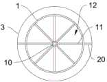
图3为本发明中用于易坍塌地层钻孔护壁的侧壁注浆装置的横向剖视图。FIG. 3 is a transverse cross-sectional view of the side wall grouting device used for the retaining wall of a borehole in an easily collapsed formation according to the present invention.
图标:1-内圆筒,2-上密封气囊,3-注浆气囊,4-下密封气囊,5-注浆管,6-第一充放气管,7-第二充放气管,8-第三充放气管,9-出浆液孔,10-中央杆,11-连接板,12-连接间隙,13-上盖板,14-上隔板,15-下隔板,16-下盖板,17-上密封仓,18-中注浆仓,19-下密封仓,20-竖隔板,21-桩孔。Icon: 1-inner cylinder, 2-upper sealing airbag, 3-grouting airbag, 4-lower sealing airbag, 5-grouting pipe, 6-first inflation and deflation pipe, 7-second inflation and deflation pipe, 8- The third air-filling and discharging pipe, 9-outlet slurry hole, 10-central rod, 11-connecting plate, 12-connecting gap, 13-upper cover plate, 14-upper partition plate, 15-lower partition plate, 16-lower cover plate , 17-upper sealing chamber, 18-in grouting chamber, 19-lower sealing chamber, 20-vertical partition, 21-pillar hole.
具体实施方式Detailed ways
为了使本发明的目的、技术方案及优点更加清楚明白,以下结合附图及实施例,对本发明进行进一步详细说明。应当理解,此处所描述的具体实施例仅仅用以解释本发明,并不用于限定本发明。In order to make the objectives, technical solutions and advantages of the present invention clearer, the present invention will be further described in detail below with reference to the accompanying drawings and embodiments. It should be understood that the specific embodiments described herein are only used to explain the present invention, but not to limit the present invention.
图1-3示出了本发明用于易坍塌地层钻孔护壁的侧壁注浆工法和装置的较佳实施方式。Figures 1-3 show the preferred embodiments of the sidewall grouting method and device used for the retaining wall of a borehole in a slumpable formation according to the present invention.
实施例1:Example 1:
本实施例中提供一种用于易坍塌地层钻孔护壁的侧壁注浆装置,该注浆装置具体包括内圆筒,沿内圆筒1的外壁从上至下依次设置有上密封气囊2、注浆气囊3和下密封气囊4,内圆筒1内竖向设有注浆管5、第一充放气管6、第二充放气管7和第三充放气管8,注浆管5依次贯穿内圆筒1和注浆气囊3,并在注浆气囊3的外壁形成出浆液孔9,第一充放气管6、第二充放气管7和第三充放气管8分别与密封气囊、注浆气囊3和下密封气囊4相连通。This embodiment provides a sidewall grouting device for a borehole wall in an easily collapsed formation. The grouting device specifically includes an inner cylinder, and an
在钻孔完成后将注浆装置放置于桩孔21内,利用第一充放气管6和第三充放气管8对上密封气囊2和下密封气囊4进行充气,使上密封气囊2和下密封气囊4与桩孔21的内壁紧贴,形成密封,以对注浆装置的位置进行固定,然后打开注浆管5,将浆液沿注浆管5和出浆液孔9注入到注浆气囊3与桩孔21内壁的空隙中,然后关闭注浆管5,利用第二充放气管7对注浆气囊3进行充气,使注浆气囊3与桩孔21的内壁紧贴,以使浆液在压力作用下渗入桩孔21周边地层,利用易坍塌地层的透水性,将注浆浆液从侧壁向周边注入,扩散到井壁周边一定范围内并固化,形成护壁结构,本注浆装置具有操作简单,材料投入少等优点,利用本注浆装置的施工工法形成施工护壁,具有施工速度快的优势。After the drilling is completed, the grouting device is placed in the
上密封气囊2、注浆气囊3和下密封气囊4的外壁比桩孔21小4~8cm,通过起吊装置将本注浆装置吊放入桩孔21内,实现在进行前述操作形成桩孔21护壁结构。The outer walls of the
在需要进行多次钻进时,可在前述操作后先对上密封气囊2、注浆气囊3和下密封气囊4进行放气,然后取出本注浆装置,再进一步对桩孔21进行钻进,钻进后的下部桩孔21也可通过本注浆装置进行来形状桩孔21护壁结构。When multiple drillings are required, the
由于易坍塌地层具有透水性,本发明的基本原理是对钻孔穿过的易坍塌地层,利用易坍塌地层的透水性,将注浆浆液从侧壁向周边注入,扩散到井壁周边一定范围内并固化,形成护壁结构。Since the easily slumpable stratum has water permeability, the basic principle of the present invention is to use the water permeability of the easily slumpable stratum to inject the grouting slurry from the side wall to the periphery, and diffuse to a certain range around the well wall. inside and solidify to form a retaining wall structure.
内圆筒1的设置用于给上密封气囊2、注浆气囊3和下密封气囊4的充气提供后壁支撑,以使上密封气囊2、注浆气囊3和下密封气囊4的外侧能与桩孔21的内壁相贴。The
内圆筒1内竖向设有中央杆10,中央杆10的上端穿出内圆筒1并置于内圆筒1的上方,中央杆10的外壁通过连接板11与内圆筒1的内壁相连,连接板11为两个以上,两个以上的连接板11沿内圆筒1的径向均匀设置形成连接架,连接架设置为两个以上并且沿内圆筒1的轴向均匀设置,如图3所示,连接板11可以设置为8个并且在中央杆10的外壁呈“米”字形设置,进而形成呈“米”字形的连接架。The
中央杆10的设置用于提升或下压本注浆装置,连接板11用于连接中央杆10和内圆筒1,并平衡内圆筒1的侧壁压力,多层设置的连接板11不仅能使中央杆10和内圆筒1的连接更加稳定,还可以使对内圆筒1侧壁压力的平衡更加均匀。The
连接架使中央杆10与内圆筒1之间留设有多个连接间隙12,第一充放气管6、第二充放气管7和第三充放气管8分别通过各个连接间隙12延伸至内圆筒1的上方,以利用连接间隙12对第一充放气管6、第二充放气管7和第三充放气管8进行固定,并使第一充放气管6、第二充放气管7和第三充放气管8的上端能引至地面,并与地面的压缩泵站相连,从而实现充气加压和释放气压,其中第一充放气管6、第二充放气管7和第三充放气管8均需穿过内圆筒1,并分别与上密封气囊2、注浆气囊3和下密封气囊4相连通。The connecting frame leaves a plurality of
内圆筒1的外壁从上至下依次设有均呈圆环形的上盖板13、上隔板14、下隔板15和下盖板16;上盖板13和上隔板14之间形成上密封仓17,上密封气囊2设置于上密封仓17内,且上密封气囊2的上下两侧分别与上盖板13和上隔板14相贴,上密封气囊2的内侧与内圆筒1的外壁相贴;上隔板14和下隔板15之间形成中注浆仓18,注浆气囊3设置于中注浆仓18内,且注浆气囊3的上下两侧分别与上隔板14和下隔板15相贴,注浆气囊3的内侧与内圆筒1的外壁相贴;下隔板15和下盖板16之间形成下密封仓19,下密封气囊4设置于下密封仓19内,且下密封气囊4的上下两侧分别与下隔板15和下盖板16相贴,下密封气囊4内侧与内圆筒1的外壁相贴。The outer wall of the
上盖板13上内圆筒1的上端相连,下盖板16与内圆筒1的下端相连,进而利用上盖板13、上隔板14、下隔板15和下盖板16在内圆筒1的外壁之间形成3个自上而下相互独立的半封闭的腔体,即是上密封仓17、中注浆仓18和下密封仓19,分别用于放置上密封气囊2、注浆气囊3和下密封气囊4,便可保证上密封气囊2、注浆气囊3和下密封气囊4的膨胀和收缩互不干扰,其中上密封气囊2、注浆气囊3和下密封气囊4分别以内嵌入式得到方式整体嵌入进各个半封闭的腔体中。The
上盖板13、上隔板14、下隔板15和下盖板16均可采用钢制材料制成。The
中注浆仓18内设有两个以上的竖隔板20,竖隔板20的上下两端分别与上隔板14和下隔板15相连,竖隔板20的内侧与内圆筒1相连,竖隔板20将中注浆仓18分隔为两个以上的放置仓,注浆气囊3设置为两个以上并且分别位于各个放置仓内;竖隔板20内横向设有注浆液通道,注浆液通道的一端在竖隔板20的外侧形成出浆液孔9,另一端在内圆筒1的内壁形成连接孔,并与注浆管5相连通。There are more than two
具体的,竖隔板20可以对称地设置为2个或4个,以形成2个或4个放置仓,竖隔板20上的注浆液通道的内径为10mm,且每一个竖隔板20上均可设置有多个注浆液通道,多个注浆液通道内侧的连接孔均与注浆管5连通,在注浆管5注浆时便可在多个方位和多个高度进行出浆。Specifically, two or four
实施例2:Example 2:
本实施例中提供一种用于易坍塌地层钻孔护壁的侧壁注浆装置的注浆工法,包括如下步骤:The present embodiment provides a grouting method for a sidewall grouting device for a borehole wall in an easily collapsed formation, including the following steps:
S1、利用钻孔装置在地层钻出桩孔21,将注浆装置放置于桩孔21中;S1, using the drilling device to drill the
S2、利用第一充放气管6和第三充放气管8对上密封气囊2和下密封气囊4进行充气,使上密封气囊2和下密封气囊4与桩孔21的内壁紧贴,形成密封;S2, use the first inflation and deflation tube 6 and the third inflation and
S3、打开注浆管5,将浆液沿注浆管5和出浆液孔9注入到注浆气囊3与桩孔21内壁的空隙中,然后关闭注浆管5;S3, open the
S4、利用第二充放气管7对注浆气囊3进行充气,使注浆气囊3与桩孔21的内壁紧贴,以使浆液在压力作用下渗入桩孔21周边地层;S4, inflate the
S5、利用第二充放气管7对注浆气囊3进行放气;S5, use the second inflation and
S6、多次重复前述S3-S5步骤;S6, repeat the aforementioned steps S3-S5 for many times;
S7、打开注浆管5并注入清水对注浆管5进行清洗;S7, open the
S8、待初凝时间达到后,利用第一充放气管6和第三充放气管8对上密封气囊2和下密封气囊4进行放气,然后将将注浆装置从桩孔21内取出。S8. After the initial setting time is reached, use the first inflation and deflation pipe 6 and the third inflation and
本注浆工法采用先钻孔后注浆方式,当易坍塌地层厚度小于等于2m时,在钻孔穿透该层0.5-1m时注浆,一次完成,当易坍塌地层厚度超过2m时,分段多次注浆。分段多次注浆的方法为:自进入该易坍塌地层2.5m,第一次注浆,固化后钻进,每钻进2m,侧壁注浆一次,钻进、注浆交替进行,直至穿透易坍塌地层。This grouting method adopts the method of drilling first and then grouting. When the thickness of the easily collapsed stratum is less than or equal to 2m, the grouting is performed when the drilled hole penetrates 0.5-1m of the layer, and it is completed at one time. grouting several times. The method of multi-stage grouting is as follows: 2.5m into the easily collapsed stratum, grouting for the first time, then drilling after solidification, every 2m of drilling, grouting the side wall once, drilling and grouting alternately until Penetrates slump-prone formations.
浆液采用掺入外加剂和膨润土的水泥浆,或水泥水玻璃双液浆,浆液的初凝时间10-15min,终注压力0.5Mpa,其中具体的参数及浆液配合比可以根据不同的地层进行确定。The slurry adopts cement slurry mixed with admixture and bentonite, or cement-water glass double-liquid slurry. The initial setting time of the slurry is 10-15min, and the final injection pressure is 0.5Mpa. The specific parameters and slurry mix ratio can be determined according to different formations. .
尽管这里参照本发明的多个解释性实施例对本发明进行了描述,但是,应该理解,本领域技术人员可以设计出很多其他的修改和实施方式,这些修改和实施方式将落在本申请公开的原则范围和精神之内。更具体地说,在本申请公开、附图和权利要求的范围内,可以对主题组合布局的组成部件和/或布局进行多种变型和改进。除了对组成部件和/或布局进行的变形和改进外,对于本领域技术人员来说,其他的用途也将是明显的。Although the present invention has been described herein with reference to a number of illustrative embodiments thereof, it should be understood that numerous other modifications and embodiments can be devised by those skilled in the art that will fall within the scope of this disclosure. within the scope and spirit of the principles. More particularly, various variations and modifications are possible in the component parts and/or arrangements of the subject combination arrangement within the scope of the present disclosure, drawings and claims. In addition to variations and modifications to the component parts and/or arrangements, other uses will also be apparent to those skilled in the art.
Claims (10)
Translated fromChinesePriority Applications (1)
| Application Number | Priority Date | Filing Date | Title |
|---|---|---|---|
| CN202011048537.7ACN112030977A (en) | 2020-09-29 | 2020-09-29 | Side wall grouting construction method and device for easy-collapse stratum drilling retaining wall |
Applications Claiming Priority (1)
| Application Number | Priority Date | Filing Date | Title |
|---|---|---|---|
| CN202011048537.7ACN112030977A (en) | 2020-09-29 | 2020-09-29 | Side wall grouting construction method and device for easy-collapse stratum drilling retaining wall |
Publications (1)
| Publication Number | Publication Date |
|---|---|
| CN112030977Atrue CN112030977A (en) | 2020-12-04 |
Family
ID=73573432
Family Applications (1)
| Application Number | Title | Priority Date | Filing Date |
|---|---|---|---|
| CN202011048537.7APendingCN112030977A (en) | 2020-09-29 | 2020-09-29 | Side wall grouting construction method and device for easy-collapse stratum drilling retaining wall |
Country Status (1)
| Country | Link |
|---|---|
| CN (1) | CN112030977A (en) |
Cited By (1)
| Publication number | Priority date | Publication date | Assignee | Title |
|---|---|---|---|---|
| CN114411741A (en)* | 2022-01-19 | 2022-04-29 | 三峡大学 | Pressure grouting device and method for pile hole protecting wall |
Citations (8)
| Publication number | Priority date | Publication date | Assignee | Title |
|---|---|---|---|---|
| JP2012241386A (en)* | 2011-05-18 | 2012-12-10 | Ohbayashi Corp | Rock mass reinforcement and injection method of grout material |
| CN106703010A (en)* | 2015-11-12 | 2017-05-24 | 华南理工大学 | Jacket-material-bed-free sleeve valve pipe grouting quick construction method |
| CN109538157A (en)* | 2018-10-18 | 2019-03-29 | 西安科技大学 | A kind of coal mine gas pre-draining borehole flexibility sealing of hole system and method |
| CN111155932A (en)* | 2020-02-20 | 2020-05-15 | 浙江省地矿建设有限公司 | Drill bit for high-pressure jet grouting pile machine |
| CN111456721A (en)* | 2020-04-16 | 2020-07-28 | 西安科技大学 | Device and method for measuring gas pressure of multistage air bag rapid hole sealing |
| CN111501761A (en)* | 2020-05-08 | 2020-08-07 | 都城伟业集团有限公司 | Offshore steel pipe pile distributed post-grouting device, pneumatic grouting assembly and construction method |
| CN111535302A (en)* | 2020-05-08 | 2020-08-14 | 东南大学 | Distributed pile side post grouting device and hydraulic grouting component of cast-in-place pile and construction method |
| CN212612486U (en)* | 2020-09-29 | 2021-02-26 | 重庆交通大学 | A side wall grouting device for borehole wall protection in easily collapsed strata |
- 2020
- 2020-09-29CNCN202011048537.7Apatent/CN112030977A/enactivePending
Patent Citations (8)
| Publication number | Priority date | Publication date | Assignee | Title |
|---|---|---|---|---|
| JP2012241386A (en)* | 2011-05-18 | 2012-12-10 | Ohbayashi Corp | Rock mass reinforcement and injection method of grout material |
| CN106703010A (en)* | 2015-11-12 | 2017-05-24 | 华南理工大学 | Jacket-material-bed-free sleeve valve pipe grouting quick construction method |
| CN109538157A (en)* | 2018-10-18 | 2019-03-29 | 西安科技大学 | A kind of coal mine gas pre-draining borehole flexibility sealing of hole system and method |
| CN111155932A (en)* | 2020-02-20 | 2020-05-15 | 浙江省地矿建设有限公司 | Drill bit for high-pressure jet grouting pile machine |
| CN111456721A (en)* | 2020-04-16 | 2020-07-28 | 西安科技大学 | Device and method for measuring gas pressure of multistage air bag rapid hole sealing |
| CN111501761A (en)* | 2020-05-08 | 2020-08-07 | 都城伟业集团有限公司 | Offshore steel pipe pile distributed post-grouting device, pneumatic grouting assembly and construction method |
| CN111535302A (en)* | 2020-05-08 | 2020-08-14 | 东南大学 | Distributed pile side post grouting device and hydraulic grouting component of cast-in-place pile and construction method |
| CN212612486U (en)* | 2020-09-29 | 2021-02-26 | 重庆交通大学 | A side wall grouting device for borehole wall protection in easily collapsed strata |
Non-Patent Citations (1)
| Title |
|---|
| 邵志中;: "灌注桩后注浆施工技术与工程实例", 中国新技术新产品, no. 15, 10 August 2012 (2012-08-10)* |
Cited By (2)
| Publication number | Priority date | Publication date | Assignee | Title |
|---|---|---|---|---|
| CN114411741A (en)* | 2022-01-19 | 2022-04-29 | 三峡大学 | Pressure grouting device and method for pile hole protecting wall |
| CN114411741B (en)* | 2022-01-19 | 2023-12-19 | 三峡大学 | A pressure grouting device and method for pile hole wall protection |
Similar Documents
| Publication | Publication Date | Title |
|---|---|---|
| CN113250200B (en) | Novel environmental protection fibre cement layering slip casting device | |
| CN107859036B (en) | A cast-in-place prefabricated composite structural pile suitable for karst areas and its construction method | |
| CN105672241B (en) | Device and method for deep seismic subsidence loess treated by jet soil breaking combined with air bag compaction | |
| CN102889958A (en) | Coal bed gas pressure direct measurement device and pressure measurement method thereof | |
| CN108457693B (en) | A method and structure of slotted grouting, hole sealing, fixed-point pressurization and expansion of seepage | |
| CN110984900A (en) | Device and method for stopping water in drilling | |
| CN113931164B (en) | Club-footed pile construction method for pre-soaking and compacting collapsible loess | |
| CN107939333A (en) | Multistage pressure-bearing type osmosis type method for sealing and device | |
| CN212612486U (en) | A side wall grouting device for borehole wall protection in easily collapsed strata | |
| CN112030977A (en) | Side wall grouting construction method and device for easy-collapse stratum drilling retaining wall | |
| CN107420100A (en) | One kind layering water plug and layering pumping system | |
| CN114278252B (en) | A water-stopping device and method of use for geological pumping tests | |
| CN110847847A (en) | Mechanical trigger type packer capable of repeatedly setting and unsetting | |
| CN208456572U (en) | Portable hydraulic fracturing and grouting hole sealing integrated device | |
| CN211666686U (en) | Packer and well structure for independent disposal of multiple layers of underground water | |
| CN214408374U (en) | Layered surrounding rock grouting reinforcement indoor model test device | |
| CN201794568U (en) | Packing sand prevention equipment of oil-gas well | |
| CN118110563A (en) | Grouting device for non-closed overburden filling | |
| CN217107117U (en) | A cutting groove construction structure for mining | |
| CN204152475U (en) | Layer-through drilling list pouch hole sealing device | |
| CN211692391U (en) | Mechanical trigger type packer capable of repeatedly setting and unsetting | |
| CN220768111U (en) | Side wall grouting device for wall protection of permeable sandy pebble stratum bored pile | |
| CN207032209U (en) | Double pipe extruding note sandy ground base processing unit | |
| RU2005139750A (en) | METHOD FOR INSULATING A FLUID-CONTAINING LAYER AND A DEVICE FOR ITS IMPLEMENTATION | |
| JPH0718651A (en) | Ground consolidating/reinforcing method |
Legal Events
| Date | Code | Title | Description |
|---|---|---|---|
| PB01 | Publication | ||
| PB01 | Publication | ||
| SE01 | Entry into force of request for substantive examination | ||
| SE01 | Entry into force of request for substantive examination | ||
| WD01 | Invention patent application deemed withdrawn after publication | Application publication date:20201204 | |
| WD01 | Invention patent application deemed withdrawn after publication |