CN112026953A - A modular self-reconfigurable hexapod robot - Google Patents
A modular self-reconfigurable hexapod robotDownload PDFInfo
- Publication number
- CN112026953A CN112026953ACN202011085892.1ACN202011085892ACN112026953ACN 112026953 ACN112026953 ACN 112026953ACN 202011085892 ACN202011085892 ACN 202011085892ACN 112026953 ACN112026953 ACN 112026953A
- Authority
- CN
- China
- Prior art keywords
- leg
- robot
- motor
- reconfigurable
- bracket
- Prior art date
- Legal status (The legal status is an assumption and is not a legal conclusion. Google has not performed a legal analysis and makes no representation as to the accuracy of the status listed.)
- Granted
Links
- 241000238631HexapodaSpecies0.000titleclaimsabstractdescription40
- 238000003032molecular dockingMethods0.000claimsabstractdescription27
- 241000270295SerpentesSpecies0.000claimsabstractdescription6
- 230000007246mechanismEffects0.000claimsdescription22
- 210000001503jointAnatomy0.000claimsdescription13
- 230000007613environmental effectEffects0.000abstractdescription3
- 230000009286beneficial effectEffects0.000abstractdescription2
- 230000009466transformationEffects0.000abstractdescription2
- 230000000903blocking effectEffects0.000description7
- 238000010586diagramMethods0.000description5
- WYTGDNHDOZPMIW-RCBQFDQVSA-NalstonineNatural productsC1=CC2=C3C=CC=CC3=NC2=C2N1C[C@H]1[C@H](C)OC=C(C(=O)OC)[C@H]1C2WYTGDNHDOZPMIW-RCBQFDQVSA-N0.000description3
- 230000008859changeEffects0.000description3
- 230000000694effectsEffects0.000description3
- 238000000034methodMethods0.000description3
- 238000004891communicationMethods0.000description2
- 230000004048modificationEffects0.000description2
- 238000012986modificationMethods0.000description2
- 230000002093peripheral effectEffects0.000description2
- 230000008569processEffects0.000description2
- 210000001364upper extremityAnatomy0.000description2
- 230000009471actionEffects0.000description1
- 230000007812deficiencyEffects0.000description1
- 238000013461designMethods0.000description1
- 238000011161developmentMethods0.000description1
- 238000005516engineering processMethods0.000description1
- 230000006872improvementEffects0.000description1
- 238000009434installationMethods0.000description1
- 230000003993interactionEffects0.000description1
Images


Classifications
- B—PERFORMING OPERATIONS; TRANSPORTING
- B62—LAND VEHICLES FOR TRAVELLING OTHERWISE THAN ON RAILS
- B62D—MOTOR VEHICLES; TRAILERS
- B62D57/00—Vehicles characterised by having other propulsion or other ground- engaging means than wheels or endless track, alone or in addition to wheels or endless track
- B62D57/02—Vehicles characterised by having other propulsion or other ground- engaging means than wheels or endless track, alone or in addition to wheels or endless track with ground-engaging propulsion means, e.g. walking members
- B62D57/032—Vehicles characterised by having other propulsion or other ground- engaging means than wheels or endless track, alone or in addition to wheels or endless track with ground-engaging propulsion means, e.g. walking members with alternately or sequentially lifted supporting base and legs; with alternately or sequentially lifted feet or skid
Landscapes
- Engineering & Computer Science (AREA)
- Chemical & Material Sciences (AREA)
- Combustion & Propulsion (AREA)
- Transportation (AREA)
- Mechanical Engineering (AREA)
- Manipulator (AREA)
Abstract
Translated fromChinese
Description
Translated fromChinese技术领域technical field
本发明涉及机器人领域,尤其是一种模块化自重构六足机器人。The invention relates to the field of robots, in particular to a modular self-reconfigurable hexapod robot.
背景技术Background technique
本部分的陈述仅仅是提供了与本发明相关的背景技术信息,不必然构成在先技术。The statements in this section merely provide background information related to the present invention and do not necessarily constitute prior art.
随着机器人技术的发展,机器人的应用领域也在不断拓展,从灾害救援到军事运输到家庭服务等等,机器人应用领域的拓展,对机器人的性能提出了更高要求,构型作为机器人的基本特性,很大程度上制约着机器人的性能。With the development of robotics technology, the application fields of robots are also expanding, from disaster rescue to military transportation to household services, etc. The expansion of robot application fields has put forward higher requirements for the performance of robots, and the configuration is the basic requirement of robots. The characteristics greatly restrict the performance of the robot.
面对复杂的地形,六足机器人有较高的稳定裕度与负载能力,而四足机器人相对于六足机器人有较大的步距,因此运动更加灵活,且有较好的通过性,蛇形机器人相对于足式机器人有较强的狭窄空间通过能力,不同构型的机器人面对某种特定环境具有较好的适应能力,发明人发现,机器人执行任务时的环境未知,而现有的机器人多数只具有单一的功能,环境适应能力相对较弱。In the face of complex terrain, the hexapod robot has a higher stability margin and load capacity, while the quadruped robot has a larger step distance than the hexapod robot, so the movement is more flexible and has better passability. Compared with the legged robot, the robot has a stronger ability to pass through narrow spaces, and the robots of different configurations have better adaptability to a certain environment. The inventor found that the environment in which the robot performs the task is unknown, and the existing Most robots have only a single function, and the ability to adapt to the environment is relatively weak.
发明内容SUMMARY OF THE INVENTION
针对现有技术存在的不足,本发明的目的是提供一种模块化自重构六足机器人,能够通过中间对接机构的松开与锁紧,使第二腿分离或者对接,实现六足机器人构型与四足机器人构型和蛇形机器人构型之间相互转变,提高机器人面对未知作业环境时的适应能力。In view of the deficiencies in the prior art, the purpose of the present invention is to provide a modular self-reconfigurable hexapod robot, which can separate or dock the second leg through the loosening and locking of the intermediate docking mechanism, so as to realize the hexapod robot mechanism. The transformation between the four-legged robot configuration and the snake-like robot configuration improves the adaptability of the robot when facing the unknown operating environment.
为了实现上述目的,本发明是通过如下的技术方案来实现:In order to achieve the above object, the present invention is realized by the following technical solutions:
一种模块化自重构六足机器人,包括机器人本体,机器人本体固定有至少四个第一腿,第一腿分两组布设于机器人本体的两侧,机器人本体在两侧的第一腿之间可拆卸安装有第二腿,第二腿横穿机器人本体设置形成机器人的蛇足,且第二腿通过中间对接结构固定于机器人本体。A modular self-reconfigurable hexapod robot, comprising a robot body, the robot body is fixed with at least four first legs, the first legs are arranged in two groups on both sides of the robot body, and the robot body is located between the first legs on both sides. A second leg is detachably installed between the two legs, the second leg is arranged across the robot body to form the snake foot of the robot, and the second leg is fixed to the robot body through the intermediate docking structure.
如上所述的机器人,第一腿包括至少四个,这样第一腿分两组布设于机器人本体的两侧,构成机器人的四足,第二腿横穿机器人本体设置,这样使得机器人具有六足,且第二腿可拆卸设置,这样机器人可在六足、四足和蛇形之间变化,提高机器人面对未知作业环境时的适应能力。In the above-mentioned robot, the first legs include at least four, so that the first legs are arranged in two groups on both sides of the robot body to form the four legs of the robot, and the second legs are arranged across the robot body, so that the robot has six legs , and the second leg is detachable, so that the robot can change between hexapods, quadrupeds and snakes, improving the robot's adaptability when facing unknown operating environments.
如上所述的一种模块化自重构六足机器人,所述中间对接机构包括动力源,动力源的输出轴设置偏心轮,偏心轮设置至少一个凸起,每一凸起连接锁紧件,锁紧件包括连杆、锁紧块和壳式轨道,连杆为L型连杆,所述凸起通过轴承与连杆的一端连接,连杆的另一端与锁紧块连接。In the above-mentioned modular self-reconfigurable hexapod robot, the intermediate docking mechanism includes a power source, an output shaft of the power source is provided with an eccentric wheel, and the eccentric wheel is provided with at least one protrusion, and each protrusion is connected to a locking member, The locking piece includes a connecting rod, a locking block and a shell-type track, the connecting rod is an L-shaped connecting rod, the protrusion is connected with one end of the connecting rod through a bearing, and the other end of the connecting rod is connected with the locking block.
动力源可为锁紧电机,偏心轮设置两个凸起,两个凸起设于偏心轮的两侧,这样偏心轮的两侧均设置用于锁紧第二腿的锁紧件,使得第二腿牢固稳定通过中间对接机构固定于机器人本体。The power source can be a locking motor, and the eccentric wheel is provided with two protrusions, and the two protrusions are provided on both sides of the eccentric wheel, so that both sides of the eccentric wheel are provided with locking pieces for locking the second leg, so that the first The two legs are firmly and stably fixed to the robot body through the intermediate docking mechanism.
如上所述的一种模块化自重构六足机器人,所述壳式轨道包括门型架,门型架的一侧设置穿过门型架侧部的轨道,锁紧块可沿着轨道直线移动,门型架在轨道的一侧设置卡槽,卡槽可容纳安装于所述第二腿的倒钩,锁紧块沿着轨道移动至设定位置后锁紧通过倒钩锁紧第二腿,通过锁紧电机带动偏心轮转动,从而带动连杆转动,因门型架提供锁紧块移动的路径,实现锁紧块沿着门型架轨道进行直线移动,进而通过锁紧块相对于门型架的伸缩运动实现对第二腿倒钩的锁紧,从而实现对第二腿的锁紧或松开。A modular self-reconfigurable hexapod robot as described above, the shell-type track includes a portal frame, one side of the portal frame is provided with a track passing through the side of the portal frame, and the locking block can move linearly along the track , the portal frame is provided with a card slot on one side of the track, the card slot can accommodate the barb installed on the second leg, the locking block moves along the track to the set position and then locks the second leg through the barb. , through the locking motor to drive the eccentric wheel to rotate, thereby driving the connecting rod to rotate, because the portal frame provides a path for the locking block to move, so that the locking block can move linearly along the portal frame track, and then pass the locking block relative to the door. The telescopic movement of the frame realizes the locking of the barbs of the second leg, thereby realizing the locking or loosening of the second leg.
如上所述的一种模块化自重构六足机器人,所述壳式轨道设置第一弹性触点,所述第二腿设置第二弹性触点,在第二腿被所述中部对接机构锁紧时,第一弹性触点和第二弹性触点可接触,第一弹性触点和第二弹性触点均为弹簧触点,当两个触点接触时,且第一弹性触点在上设置,第二触点在下设置。A modular self-reconfigurable hexapod robot as described above, the shell-type track is provided with a first elastic contact, the second leg is provided with a second elastic contact, and the second leg is locked by the middle docking mechanism When tight, the first elastic contact and the second elastic contact can be in contact. The first elastic contact and the second elastic contact are both spring contacts. When the two contacts are in contact, the first elastic contact is on the upper set, the second contact is set below.
如上所述的一种模块化自重构六足机器人,为了保证锁紧块的直线移动路径,所述门型架的一侧内部设置凸块,所述轨道穿过该凸块和靠近该凸块的门型架侧部设置;In the above-mentioned modular self-reconfigurable hexapod robot, in order to ensure the linear movement path of the locking block, a convex block is arranged inside one side of the gantry, and the rail passes through the convex block and is close to the convex block. The gantry side part of the block is set;
所述锁紧块远离所述连杆的一端为设为楔形。One end of the locking block away from the connecting rod is wedge-shaped.
如上所述的一种模块化自重构六足机器人,所述第一腿包括偏航关节、第一俯仰关节和第二俯仰关节;偏航关节包括上部电机和第二支架,上部电机固定于所述机器人本体,上部电机的输出轴通过舵盘与第二支架刚性连接。A modular self-reconfigurable hexapod robot as described above, the first leg includes a yaw joint, a first pitch joint and a second pitch joint; the yaw joint includes an upper motor and a second bracket, and the upper motor is fixed on the In the robot body, the output shaft of the upper motor is rigidly connected with the second bracket through the rudder plate.
如上所述的一种模块化自重构六足机器人,所述第一俯仰关节包括中部腿节,中部电机通过第一支架固定于所述第二支架,第一支架和第二支架垂直,中部腿节一端与中部电机输出轴固定,另一端与底部电机固定;A modular self-reconfigurable hexapod robot as described above, the first pitching joint includes a middle leg section, the middle motor is fixed to the second bracket through a first bracket, the first bracket and the second bracket are perpendicular, and the middle One end of the leg section is fixed with the output shaft of the middle motor, and the other end is fixed with the bottom motor;
第二俯仰关节包括第一末端腿节,第一末端腿节通过第一支架固定于底部电机输出轴。The second pitch joint includes a first end leg section, and the first end leg section is fixed to the bottom motor output shaft through the first bracket.
如上所述的一种模块化自重构六足机器人,所述第二腿包括第二末端腿节和第三末端腿节,第二末端腿节和第三末端腿节设于机器人本体的两侧,且二者由多个电机依次连接并形成多个俯仰关节和多个偏航关节。A modular self-reconfigurable hexapod robot as described above, the second leg includes a second end leg section and a third end leg section, and the second end leg section and the third end leg section are arranged on two sides of the robot body. The two sides are connected by a plurality of motors in sequence to form a plurality of pitch joints and a plurality of yaw joints.
如上所述的一种模块化自重构六足机器人,所述第二腿中中部的电机侧部设置所述的倒钩,倒钩为L型,这样倒钩在到达门型架卡槽时,锁紧块移动,可与门型架夹紧倒钩较长的一侧,而倒钩的较短一侧设于锁紧块楔形端部的一侧,保证中间对接结构对第二腿的锁紧。In the above-mentioned modular self-reconfigurable hexapod robot, the barb is provided on the side of the motor in the middle of the second leg, and the barb is L-shaped, so that when the barb reaches the slot of the portal frame , the locking block moves and can clamp the longer side of the barb with the portal frame, while the shorter side of the barb is set on the side of the wedge-shaped end of the locking block to ensure that the intermediate docking structure has no effect on the second leg. lock.
如上所述的一种模块化自重构六足机器人,为了进一步增加第二腿的运动灵活性,所述第二腿中第二末端腿节、第三末端腿节和连接相邻两个电机之间的支架均设置可转动的被动轮,被动轮设于各结构件的两侧,以保证第二腿的独立行走能力。In the above-mentioned modular self-reconfigurable hexapod robot, in order to further increase the movement flexibility of the second leg, the second end leg segment and the third end leg segment in the second leg are connected to two adjacent motors. The brackets between are provided with rotatable passive wheels, and the passive wheels are arranged on both sides of each structural member to ensure the independent walking ability of the second leg.
上述本发明的有益效果如下:The above-mentioned beneficial effects of the present invention are as follows:
1)本发明通过中间对接机构与第二腿的设计,使机器人能够通过中间对接机构将第二腿脱离或者锁紧,使六足机器人构型与四足机器人和蛇形机器人构型之间相互转变,六足机器人有较高的稳定裕度与承载能力,而四足机器人步距大运动灵活,且四足机器人构型可以有效减小机器人宽度,提高通过性,蛇形机器人构型可以通过狭小空间,通过自重构可转换设置,机器人可以有效提高环境适应能力。1) The present invention enables the robot to disengage or lock the second leg through the intermediate docking mechanism through the design of the intermediate docking mechanism and the second leg, so that the configuration of the hexapod robot, the quadruped robot and the snake robot configuration can interact with each other. Change, the hexapod robot has a high stability margin and carrying capacity, while the quadruped robot has a large step distance and flexible movement, and the quadruped robot configuration can effectively reduce the width of the robot and improve the passability. The snake robot configuration can pass In a small space, the robot can effectively improve its environmental adaptability through self-reconfiguration and convertible settings.
2)本发明中间对接机构中通过锁紧件的设置,可带动锁紧件中连杆的转动,从而带动锁紧块沿着壳式轨道进行直线移动,壳式轨道通过轨道限制锁紧块进行直线运动,并通过门型架卡槽的设置,为第二腿与中间对接机构的锁紧连接提供空间。2) The setting of the locking member in the intermediate docking mechanism of the present invention can drive the rotation of the connecting rod in the locking member, thereby driving the locking block to move linearly along the shell-type track, and the shell-type track restricts the locking block through the track. Linear movement, and through the setting of the card slot of the portal frame, provides space for the locking connection between the second leg and the intermediate docking mechanism.
3)本发明通过第二腿倒钩的设置,可设于门型架卡槽位置处,并通过锁紧块的移动,通过锁紧块与门型架的一侧配合实现对倒钩的锁紧,倒钩的设置,可保证中间对接结构对第二腿的锁紧作用。3) In the present invention, through the setting of the second leg barb, it can be set at the position of the slot of the portal frame, and through the movement of the locking block, the locking of the barb can be realized by the cooperation of the locking block and one side of the portal frame. The setting of the barb can ensure the locking effect of the middle butt structure on the second leg.
附图说明Description of drawings
构成本发明的一部分的说明书附图用来提供对本发明的进一步理解,本发明的示意性实施例及其说明用于解释本发明,并不构成对本发明的不当限定。The accompanying drawings forming a part of the present invention are used to provide further understanding of the present invention, and the exemplary embodiments of the present invention and their descriptions are used to explain the present invention, and do not constitute an improper limitation of the present invention.
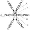
图1是本发明根据一个或多个实施方式的一种模块化自重构六足机器人的俯视图。FIG. 1 is a top view of a modular self-reconfigurable hexapod robot according to one or more embodiments of the present invention.
图2是本发明根据一个或多个实施方式的一种模块化自重构六足机器人的第一腿结构示意图。FIG. 2 is a schematic diagram of a first leg structure of a modular self-reconfigurable hexapod robot according to one or more embodiments of the present invention.
图3是本发明根据一个或多个实施方式的一种模块化自重构六足机器人的中间对接结构示意图。FIG. 3 is a schematic diagram of the intermediate docking structure of a modular self-reconfigurable hexapod robot according to one or more embodiments of the present invention.
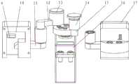
图4是本发明根据一个或多个实施方式的一种模块化自重构六足机器人的第二腿结构示意图。FIG. 4 is a schematic diagram of a second leg structure of a modular self-reconfigurable hexapod robot according to one or more embodiments of the present invention.
图5是本发明根据一个或多个实施方式的四足构型机器人结构示意图。FIG. 5 is a schematic structural diagram of a quadruped robot according to one or more embodiments of the present invention.
图中:为显示各部位位置而夸大了互相间间距或尺寸,示意图仅作示意。In the figure: The distance or size between each other is exaggerated to show the position of each part, and the schematic diagram is only for illustration.
其中:1.上部电机,2.舵盘,3.第二支架,4.第一支架,5.中部电机,6.中部腿节,7.底部电机,8.第一末端腿节,9.第一弹簧触点,10.壳式轨道,11.楔形块,12连杆,13端盖,14.滚针轴承,15.偏心轮,16.锁紧电机,17.轨道端盖,18一号电机,19二号电机,20.三号电机,21.四号电机,22.第二弹簧触点,23.倒钩,24.五号电机,25.六号电机,26.七号电机,27.八号电机,28.九号电机,29.被动轮,30.阻隔板,31.带轮阻隔板,32.带轮宽U支架。Among them: 1. Upper motor, 2. Rudder plate, 3. Second bracket, 4. First bracket, 5. Middle motor, 6. Middle leg section, 7. Bottom motor, 8. First end leg section, 9. The first spring contact, 10. Shell track, 11. Wedge block, 12 connecting rod, 13 End cover, 14. Needle bearing, 15. Eccentric wheel, 16. Lock motor, 17. Track end cover, 18 a No. 1 motor, No. 19 No. 2 motor, 20. No. 3 motor, 21. No. 4 motor, 22. No. 2 spring contact, 23. Barb, 24. No. 5 motor, 25. No. 6 motor, 26. No. 7 motor , 27. No. 8 motor, 28. No. 9 motor, 29. Passive wheel, 30. Blocking plate, 31. Blocking plate with pulley, 32. Wide U bracket with pulley.
具体实施方式Detailed ways
应该指出,以下详细说明都是例示性的,旨在对本发明提供进一步的说明。除非另有指明,本发明使用的所有技术和科学术语具有与本发明所属技术领域的普通技术人员通常理解的相同含义。It should be noted that the following detailed description is exemplary and intended to provide further explanation of the invention. Unless otherwise defined, all technical and scientific terms used herein have the same meaning as commonly understood by one of ordinary skill in the art to which this invention belongs.
需要注意的是,这里所使用的术语仅是为了描述具体实施方式,而非意图限制根据本发明的示例性实施方式。如在这里所使用的,除非本发明另外明确指出,否则单数形式也意图包括复数形式,此外,还应当理解的是,当在本说明书中使用术语“包含”和/或“包括”时,其指明存在特征、步骤、操作、器件、组件和/或它们的组合;It should be noted that the terminology used herein is for the purpose of describing specific embodiments only, and is not intended to limit the exemplary embodiments according to the present invention. As used herein, unless the invention clearly dictates otherwise, the singular is intended to include the plural as well, and it is also to be understood that when the terms "comprising" and/or "including" are used in this specification, Indicate the presence of features, steps, operations, devices, components and/or combinations thereof;
为了方便叙述,本发明中如果出现“上”、“下”、“左”“右”字样,仅表示与附图本身的上、下、左、右方向一致,并不对结构起限定作用,仅仅是为了便于描述本发明和简化描述,而不是指示或暗示所指的设备或元件必须具有特定的方位,以特定的方位构造和操作,因此不能理解为对本发明的限制。For the convenience of description, if the words "up", "down", "left" and "right" appear in the present invention, it only means that the directions of up, down, left and right are consistent with the drawings themselves, and do not limit the structure. It is for the convenience of describing the present invention and simplifying the description, rather than indicating or implying that the device or element referred to must have a specific orientation, be constructed and operate in a specific orientation, and therefore should not be construed as a limitation of the present invention.
术语解释部分:本发明中的术语“安装”、“相连”、“连接”、“固定”等术语应做广义理解,例如,可以是固定连接,也可以是可拆卸连接,或为一体;可以是机械连接,也可以是电连接,可以是直接连接,也可以是通过中间媒介间接相连,可以是两个元件内部连接,或者两个元件的相互作用关系,对于本领域的普通技术人员而言,可以根据具体情况理解上述术语在本发明的具体含义。Terminology explanation part: the terms "installation", "connection", "connection", "fixation" and other terms in the present invention should be understood in a broad sense, for example, it may be a fixed connection, a detachable connection, or an integrated; It can be a mechanical connection, it can also be an electrical connection, it can be a direct connection, it can also be indirectly connected through an intermediate medium, it can be an internal connection between two elements, or an interaction relationship between two elements, for those of ordinary skill in the art. , the specific meanings of the above terms in the present invention can be understood according to specific situations.
正如背景技术所介绍的,现有技术中存在机器人的构型较为单一、环境适应能力较差的问题,为了解决如上的技术问题,本发明提出了一种模块化自重构六足机器人。As described in the background art, there are problems in the prior art that the robot has a relatively simple configuration and poor environmental adaptability. In order to solve the above technical problems, the present invention proposes a modular self-reconfigurable hexapod robot.
本发明的一种典型的实施方式中,参考图1所示,一种模块化自重构六足机器人,包括第一腿Ⅰ,机器人本体Ⅱ,第二腿Ⅲ和中间对接机构Ⅳ,机器人本体固定有四个第一腿,第一腿分两组布设于机器人本体的两侧,每一侧各布设两个,机器人本体在两侧的第一腿之间固定有第二腿,第二腿横穿机器人本体设置,且第二腿通过中间对接结构固定于机器人本体。In a typical embodiment of the present invention, referring to FIG. 1 , a modular self-reconfigurable hexapod robot includes a first leg I, a robot body II, a second leg III and an intermediate docking mechanism IV, and the robot body Four first legs are fixed. The first legs are arranged in two groups on both sides of the robot body, two on each side. The robot body is fixed with a second leg between the first legs on both sides. It is arranged across the robot body, and the second leg is fixed to the robot body through the intermediate docking structure.
机器人本体具有设定的长度和宽度,每一侧相邻两第一腿之间的角度为60°,且第一腿靠近其的第二腿之间的角度为60°。The robot body has a set length and width, the angle between two adjacent first legs on each side is 60°, and the angle between the second legs adjacent to the first leg is 60°.
第一腿Ⅰ通过上部电机1用螺钉固定在机器人本体Ⅱ四个边角上,中间对接机构Ⅳ通过锁紧电机16用螺钉固定在机器人本体Ⅱ中间位置,第二腿Ⅲ通过中间对接机构Ⅳ锁紧在机器人本体Ⅱ中间位置。The first leg I is fixed on the four corners of the robot body II with screws through the upper motor 1, the intermediate docking mechanism IV is fixed to the middle position of the robot body II with screws through the locking
以机器人本体的一侧为前,这样第一腿包括两根前腿和两根后腿,前腿与后腿为普通腿,均有3个转动关节,两个俯仰关节,一个偏转关节。Taking one side of the robot body as the front, the first leg includes two front legs and two rear legs, and the front and rear legs are common legs, each with 3 rotating joints, two pitching joints, and one yaw joint.
参考图2所示,第一腿Ⅰ包括偏航关节、第一俯仰关节和第二俯仰关节。偏航关节包括上部电机1和第二支架3,上部电机1通过螺钉固定在机器人本体Ⅱ上,上部电机1的输出轴通过舵盘2与第二支架3用螺钉刚性连接。Referring to Fig. 2, the first leg I includes a yaw joint, a first pitch joint and a second pitch joint. The yaw joint includes an upper motor 1 and a
第一俯仰关节包括第一支架4、中部电机5、中部腿节6,中部电机5通过第一支架4用螺栓固定在第二支架3上,第一支架和第二支架垂直,中部腿节6一端通过第二支架和舵盘用螺钉固定在中部电机5输出轴,另一端与底部电机7固定;The first pitch joint includes a
第二俯仰关节包括底部电机7、第一末端腿节8,底部电机7通过第一支架用螺栓固定在中部腿节6上,第一末端腿节8通过第一支架固定在底部电机输出轴上。The second pitch joint includes a
参考图3所示,中间对接机构Ⅳ以动力源的输出轴中心线为对称结构,中间对接机构可将第二腿固定于机器人本体,中间对接机构包括锁紧电机16、偏心轮15和锁紧件,锁紧电机16通过螺钉固定在机器人本体Ⅱ上,锁紧电机输出轴通过舵盘连接偏心轮15,锁紧电机的输出轴与水平面垂直,连接舵盘,偏心轮15的两侧均具有凸起,每一凸起均设置滚针轴承,这样在舵盘两侧各设置一套锁紧件。Referring to Fig. 3, the intermediate docking mechanism IV takes the centerline of the output shaft of the power source as a symmetrical structure. The intermediate docking mechanism can fix the second leg to the robot body. The intermediate docking mechanism includes a locking
锁紧件包括连杆、锁紧块和壳式轨道,锁紧块为楔形块便于保证锁紧效果,舵盘通过偏心轮15和滚针轴承14连接连杆12,连杆12通过滚针轴承14连接楔形块11,锁紧电机16转动带动楔形块11在壳式轨道10内进给运动,通过进给运动完成锁紧与脱离过程。The locking piece includes a connecting rod, a locking block and a shell-type track. The locking block is a wedge-shaped block to ensure the locking effect. The steering wheel is connected to the connecting
其中,连杆12为L型,连杆12的一端与楔形块11的端部连接,另一端设置端盖13,端盖13可覆盖滚针轴承14,滚针轴承14设于偏心轮的侧部,这样偏心轮15通过滚针轴承14带动连杆12转动。The connecting
壳式轨道10包括门型架,门型架的一侧设置穿过门型架侧部的轨道,因楔形块的宽度方向被壳式轨道限制,这样连杆转动带动楔形块沿着轨道运动,壳式轨道10在楔形块11的一侧设置有第一弹簧触点9,这样楔形块11在运动至设定位置时可触动第一弹簧触点9,第一弹簧触点和第二弹簧触点实现接触,实现机器人与第二腿Ⅲ直接通信功能;The shell-
其中,需要说明的是,第一弹簧触点在上设置,第二弹簧触点在下设置,第一弹簧触点与机器人的四足控制器连接,第二弹簧触点与机器人的蛇形控制器连接,即机器人有两个控制单元,当第一弹簧触点与第二弹簧触点接触时,由两个控制单元中其中一个控制单元进行控制即可,控制单元都为PLC控制器或其他类型的控制器。Among them, it should be noted that the first spring contact is set on the top, the second spring contact is set on the bottom, the first spring contact is connected to the quadruped controller of the robot, and the second spring contact is connected to the serpentine controller of the robot. Connection, that is, the robot has two control units. When the first spring contact is in contact with the second spring contact, it can be controlled by one of the two control units. The control units are all PLC controllers or other types. 's controller.
另外,在机器人本体仅固定有第一腿时,由四足控制器(四足控制器控制第一腿各个电机的动作)控制各个第一腿的动作,第二腿由蛇形控制器进行控制,即蛇形控制器与第二腿的各个电机分别单独连接。In addition, when only the first leg is fixed on the robot body, the action of each first leg is controlled by the quadruped controller (the quadruped controller controls the movements of each motor of the first leg), and the second leg is controlled by the serpentine controller , that is, the serpentine controller is individually connected to each motor of the second leg.
壳式轨道10门型架具有设定的厚度,门型架靠近锁紧电机的一侧在内侧设置凸块,轨道穿过门型架的一侧和凸块设置,保证轨道的长度,门型架在轨道的一侧形成卡槽,第二腿设置的倒钩可运动至卡槽处,锁紧第二腿。Shell-
进一步,在门型架的一侧面设置轨道端盖17,轨道端盖17设于远离第二腿的另一侧,轨道端盖用于覆盖门型架的一侧,另一侧便于第二腿倒钩进入卡槽位置处。Further, a
参考图4所示,第二腿Ⅲ包括第二末端腿节和第三末端腿节,第二末端腿节和第三末端腿节设于机器人本体的两侧,且这两个末端腿节由多个电机依次连接,形成五个俯仰关节和四个偏航关节,相邻两个电机可通过支架连接,支架有多种形式。Referring to Figure 4, the second leg III includes a second end leg section and a third end leg section, the second end leg section and the third end leg section are arranged on both sides of the robot body, and the two end leg sections are formed by Multiple motors are connected in sequence to form five pitch joints and four yaw joints, and two adjacent motors can be connected through brackets, and the brackets have various forms.
具体地,一号电机18通过舵盘与第二支架用螺栓与第二末端腿节连接,一号电机18依次通过第一支架、第二支架、舵盘与二号电机19用螺栓连接,二号电机19依次通过第一支架、阻隔板、带轮U型支架32、舵盘与三号电机20相连,三号电机20依次通过第一支架、第二支架、舵盘用螺栓与四号电机21连接。Specifically, the No. 1
四号电机21依次通过带轮阻隔板31、第二支架、舵盘用螺栓与五号电机24连接,五号电机24依次通过第一支架、第二支架、舵盘与六号电机25用螺栓连接,六号电机25通过依次舵盘、带轮宽U支架、第一支架用螺栓与七号电机26连接,七号电机26依次通过舵盘、第二支架、阻隔板30、第一支架用螺栓与八号电机27连接。The No. 4
八号电机27依次通过舵盘、第二支架、第一支架用螺栓与九号电机28相连,九号电机28依次通过舵盘、第二支架用螺栓与第三末端腿节连接。第二末端腿节和第三末端腿节分布于中间对接结构的两侧。The No. 8
一号电机、三号电机、五号电机、七号电机、九号电机为俯仰关节,二号电机、四号电机、六号电机、八号电机为偏航关节,各个电机与腿节之间刚性连接,第二腿在脱离后有独立运动能力。The No. 1 motor, No. 3 motor, No. 5 motor, No. 7 motor, No. 9 motor are pitch joints, No. 2 motor, No. 4 motor, No. 6 motor, No. 8 motor are yaw joints. Rigid connection, the second leg has the ability to move independently after disengagement.
其中,需要注意的是,相邻两电机之间、电机与第一末端支腿、电机与第二末端支腿中部分第一支架与第二支架固定,且垂直设置,比如三号电机与四号电机之间的第一支架和第二支架是垂直并连接的,所有的第一支架的宽度可相同或相异,所有的第二支架的宽度可相同或相异,都可根据相应电机做出尺寸的调整。Among them, it should be noted that part of the first bracket and the second bracket between the adjacent two motors, the motor and the first end leg, the motor and the second end leg are fixed and vertically arranged, such as the third motor and the fourth The first bracket and the second bracket between the No. 1 motors are vertical and connected, the width of all the first brackets can be the same or different, and the width of all the second brackets can be the same or different, which can be made according to the corresponding motor. out size adjustment.
进一步,第一支架和第二支架均为U型,便于从相应电机的两侧进行固定;阻隔板和带轮阻隔板均具有设定的厚度,内部可中空,且可为倒T型,起到支撑与增厚作用,便于同相邻结构件的连接,可实现部分第一支架或第二支架与带轮宽U型支架的连接。Further, the first bracket and the second bracket are both U-shaped, which is convenient for fixing from both sides of the corresponding motor; the blocking plate and the pulley blocking plate have a set thickness, the interior can be hollow, and can be an inverted T-shaped. In order to support and thicken, it is convenient to connect with adjacent structural parts, and can realize the connection between part of the first bracket or the second bracket and the U-shaped bracket with the width of the pulley.
此外,需要说明的是,本实施例中,舵盘设于每一电机的两侧,舵盘直径为20mm,其为圆柱状,且舵盘盘面均布有多个螺纹孔,可以是8个;舵盘一侧通过周边螺纹孔与第一支架或第二支架对应周边通孔用螺钉刚性连接,舵盘另一侧固定在各电机转轴上,各电机均为舵机,舵机转轴通过舵盘带动第一支架或第二支架转动传递动力。In addition, it should be noted that in this embodiment, the rudder discs are arranged on both sides of each motor, the diameter of the rudder disc is 20mm, it is cylindrical, and the rudder disc surface is evenly distributed with a plurality of threaded holes, which can be 8 ;One side of the steering wheel is rigidly connected with the corresponding peripheral through holes of the first bracket or the second bracket through the peripheral threaded holes, and the other side of the steering wheel is fixed on the rotating shaft of each motor, each motor is a steering gear, and the rotating shaft of the steering gear passes through the rudder. The disk drives the first bracket or the second bracket to rotate and transmit power.
为了实现第二腿在脱离后有独立运动能力,带轮阻隔板两侧、带轮宽U支架两侧均用螺栓安装有可转动的被动轮29,被动轮可自由转动,在四号电机和五号电机的第一支架的一侧用螺钉紧固有倒钩22,倒钩可卡入门型架轨道10的卡槽处,与中间对接机构Ⅳ上楔形块11配合完成对接与脱离功能,倒钩22上安装有第二弹簧触点21与中间对接机构Ⅳ中第一弹簧触点9完成直接通信功能。In order to realize the independent movement ability of the second leg after it is disengaged, the rotatable
进一步,倒钩22为L型,且倒钩的一端与第一支架固定,中间对接结构的两侧均设置连杆和壳体轨道结构,这样一侧的倒钩用于同一侧的壳体轨道卡槽配合,另一侧的倒钩用于同另一侧的壳体轨道卡槽配合,通过中间对接结构实现对第二腿的锁紧,将第二腿固定于机器人本体。Further, the
上述模块化自重构六足机器人工作过程如下,中间对接机构Ⅳ中的锁紧电机16转动,通过偏心轮15、滚针轴承14、连杆12带动楔形块11在壳式轨道10内做进给运动,与第二腿Ⅲ中的倒钩11配合,完成第二腿Ⅲ的锁紧与脱离,实现机器人构型变化。The working process of the above-mentioned modular self-reconfigurable hexapod robot is as follows. The locking
参考图5所示,第二腿Ⅲ与中间对接机构脱离后,机器人可以作为蛇形机器人独立运动,机器人本体Ⅱ在第一腿Ⅰ的支撑下作为四足机器人运动,并且可以通过前腿向前旋转,后腿向后旋转,降低机器人宽度,提高通过性;参考图1所示,第二腿Ⅲ锁紧后配合第一腿Ⅰ使机器人作为六足机器人运动。Referring to Figure 5, after the second leg III is disengaged from the intermediate docking mechanism, the robot can move independently as a snake-like robot, and the robot body II moves as a quadruped robot under the support of the first leg I, and can move forward through the front legs. Rotation, the rear legs rotate backwards, reducing the width of the robot and improving the passability; as shown in Figure 1, the second leg III is locked and then cooperates with the first leg I to make the robot move as a hexapod robot.
以上所述仅为本发明的优选实施例而已,并不用于限制本发明,对于本领域的技术人员来说,本发明可以有各种更改和变化。凡在本发明的精神和原则之内,所作的任何修改、等同替换、改进等,均应包含在本发明的保护范围之内。The above descriptions are only preferred embodiments of the present invention, and are not intended to limit the present invention. For those skilled in the art, the present invention may have various modifications and changes. Any modification, equivalent replacement, improvement, etc. made within the spirit and principle of the present invention shall be included within the protection scope of the present invention.
Claims (10)
Translated fromChinesePriority Applications (1)
| Application Number | Priority Date | Filing Date | Title |
|---|---|---|---|
| CN202011085892.1ACN112026953B (en) | 2020-10-12 | 2020-10-12 | Modular self-reconstruction hexapod robot |
Applications Claiming Priority (1)
| Application Number | Priority Date | Filing Date | Title |
|---|---|---|---|
| CN202011085892.1ACN112026953B (en) | 2020-10-12 | 2020-10-12 | Modular self-reconstruction hexapod robot |
Publications (2)
| Publication Number | Publication Date |
|---|---|
| CN112026953Atrue CN112026953A (en) | 2020-12-04 |
| CN112026953B CN112026953B (en) | 2021-09-28 |
Family
ID=73572555
Family Applications (1)
| Application Number | Title | Priority Date | Filing Date |
|---|---|---|---|
| CN202011085892.1AExpired - Fee RelatedCN112026953B (en) | 2020-10-12 | 2020-10-12 | Modular self-reconstruction hexapod robot |
Country Status (1)
| Country | Link |
|---|---|
| CN (1) | CN112026953B (en) |
Cited By (1)
| Publication number | Priority date | Publication date | Assignee | Title |
|---|---|---|---|---|
| CN116279894A (en)* | 2023-04-28 | 2023-06-23 | 深圳小象电动科技有限公司 | A deformable folding hexapod robot |
Citations (8)
| Publication number | Priority date | Publication date | Assignee | Title |
|---|---|---|---|---|
| GB2301414A (en)* | 1995-05-22 | 1996-12-04 | British Gas Plc | Pipeline vehicle |
| CN202225936U (en)* | 2011-08-18 | 2012-05-23 | 天津理工大学 | Reconfiguration module of reconfigurable modular robot |
| CN102765087A (en)* | 2012-07-31 | 2012-11-07 | 东南大学 | Modular self-reconfigurable robot and method for controlling deformation thereof |
| CN105691483A (en)* | 2016-01-15 | 2016-06-22 | 北京工业大学 | Hexapod walking robot |
| CN110154008A (en)* | 2019-06-12 | 2019-08-23 | 杭星辰 | Snakelike/quadruped robot based on mimicry |
| CN209814144U (en)* | 2019-01-28 | 2019-12-20 | 南昌大学 | A Novel Reconfigurable Hexapod Robotic Device |
| CN111197675A (en)* | 2020-02-25 | 2020-05-26 | 常州机电职业技术学院 | A bionic hexapod pipeline robot |
| CN111216141A (en)* | 2020-02-03 | 2020-06-02 | 北京邮电大学 | A dockable and reconfigurable spherical robot |
- 2020
- 2020-10-12CNCN202011085892.1Apatent/CN112026953B/ennot_activeExpired - Fee Related
Patent Citations (8)
| Publication number | Priority date | Publication date | Assignee | Title |
|---|---|---|---|---|
| GB2301414A (en)* | 1995-05-22 | 1996-12-04 | British Gas Plc | Pipeline vehicle |
| CN202225936U (en)* | 2011-08-18 | 2012-05-23 | 天津理工大学 | Reconfiguration module of reconfigurable modular robot |
| CN102765087A (en)* | 2012-07-31 | 2012-11-07 | 东南大学 | Modular self-reconfigurable robot and method for controlling deformation thereof |
| CN105691483A (en)* | 2016-01-15 | 2016-06-22 | 北京工业大学 | Hexapod walking robot |
| CN209814144U (en)* | 2019-01-28 | 2019-12-20 | 南昌大学 | A Novel Reconfigurable Hexapod Robotic Device |
| CN110154008A (en)* | 2019-06-12 | 2019-08-23 | 杭星辰 | Snakelike/quadruped robot based on mimicry |
| CN111216141A (en)* | 2020-02-03 | 2020-06-02 | 北京邮电大学 | A dockable and reconfigurable spherical robot |
| CN111197675A (en)* | 2020-02-25 | 2020-05-26 | 常州机电职业技术学院 | A bionic hexapod pipeline robot |
Non-Patent Citations (1)
| Title |
|---|
| 张国腾 等: "基于虚拟模型的四足机器人对角小跑步态控制方法", 《机器人》* |
Cited By (1)
| Publication number | Priority date | Publication date | Assignee | Title |
|---|---|---|---|---|
| CN116279894A (en)* | 2023-04-28 | 2023-06-23 | 深圳小象电动科技有限公司 | A deformable folding hexapod robot |
Also Published As
| Publication number | Publication date |
|---|---|
| CN112026953B (en) | 2021-09-28 |
Similar Documents
| Publication | Publication Date | Title |
|---|---|---|
| CN108748124A (en) | Snake-shaped robot | |
| CN103332231B (en) | Removable module self-reorganization robot | |
| CN112873266B (en) | Humanoid robot and two-degree-of-freedom modularized humanoid robot joint thereof | |
| CN108818551A (en) | A kind of Bionic Ant six-leg robot | |
| CN105151153A (en) | Wheel-foot hybrid mode hexapod robot moving platform | |
| CN110065054B (en) | Multi-section driving master-slave type snake-shaped robot | |
| CN109484510B (en) | Robot walking mechanism | |
| CN109436090A (en) | A kind of novel Omni-mobile platform | |
| US20210205983A1 (en) | Self-reconfigurable robot module and self-reconfigurable robot | |
| CN112026953A (en) | A modular self-reconfigurable hexapod robot | |
| CN112026950B (en) | A wheel-legged composite climbing robot | |
| CN108555894B (en) | Pipeline creeping robot | |
| CN109533075A (en) | Biped climbing robot | |
| CN104786208A (en) | Regular-tetrahedron-based self-reconfigurable robot unit module mechanism | |
| CN103802125A (en) | Single-degree-of-freedom rotary joint module | |
| CN202847864U (en) | Single-chain type modularized self-reconfiguration robot | |
| CN105667621B (en) | A kind of modular reconfigurable climbing robot and its climb wall method | |
| CN111924019A (en) | Eight-degree-of-freedom disc type brushless motor driven quadruped robot | |
| CN110371208B (en) | A single-degree-of-freedom retractable rotating crawling robot based on scissor mechanism | |
| CN103273499B (en) | Compact machines people modularized joint and robot | |
| CN206263949U (en) | A kind of three flat two turns of five-freedom parallel structures | |
| CN103010329B (en) | Biped walking travel mechanism | |
| CN115122297A (en) | A Reconfigurable Creeping Machine Based on Innovative Track Design | |
| CN210083394U (en) | A quadruped crawling robot with multi-degree-of-freedom spine | |
| CN106625591A (en) | Five-degrees-of-freedom parallel mechanism achieving three-degrees-of-freedom translational motion and two-degrees-of-freedom rotational motion |
Legal Events
| Date | Code | Title | Description |
|---|---|---|---|
| PB01 | Publication | ||
| PB01 | Publication | ||
| SE01 | Entry into force of request for substantive examination | ||
| SE01 | Entry into force of request for substantive examination | ||
| GR01 | Patent grant | ||
| GR01 | Patent grant | ||
| CF01 | Termination of patent right due to non-payment of annual fee | Granted publication date:20210928 | |
| CF01 | Termination of patent right due to non-payment of annual fee |