CN112025271A - Automatic assembling machine for terminal box inserting pieces - Google Patents
Automatic assembling machine for terminal box inserting piecesDownload PDFInfo
- Publication number
- CN112025271A CN112025271ACN202010960259.6ACN202010960259ACN112025271ACN 112025271 ACN112025271 ACN 112025271ACN 202010960259 ACN202010960259 ACN 202010960259ACN 112025271 ACN112025271 ACN 112025271A
- Authority
- CN
- China
- Prior art keywords
- block
- nut
- piece
- cylinder
- insert
- Prior art date
- Legal status (The legal status is an assumption and is not a legal conclusion. Google has not performed a legal analysis and makes no representation as to the accuracy of the status listed.)
- Granted
Links
- 230000007246mechanismEffects0.000claimsabstractdescription52
- 238000009434installationMethods0.000claimsabstractdescription22
- 238000012545processingMethods0.000claimsabstractdescription10
- 238000012546transferMethods0.000claimsdescription19
- 238000001514detection methodMethods0.000claimsdescription5
- 238000000605extractionMethods0.000claimsdescription3
- 238000004519manufacturing processMethods0.000abstractdescription10
- 238000005192partitionMethods0.000description17
- 238000000034methodMethods0.000description13
- 238000010586diagramMethods0.000description12
- 230000008569processEffects0.000description11
- 239000000243solutionSubstances0.000description9
- 230000009471actionEffects0.000description4
- 230000000903blocking effectEffects0.000description3
- 230000032258transportEffects0.000description2
- 230000009286beneficial effectEffects0.000description1
- 230000007812deficiencyEffects0.000description1
- 230000005484gravityEffects0.000description1
- 238000001746injection mouldingMethods0.000description1
- 238000003780insertionMethods0.000description1
- 230000037431insertionEffects0.000description1
- 230000009191jumpingEffects0.000description1
- 238000012986modificationMethods0.000description1
- 230000004048modificationEffects0.000description1
Images


Classifications
- B—PERFORMING OPERATIONS; TRANSPORTING
- B23—MACHINE TOOLS; METAL-WORKING NOT OTHERWISE PROVIDED FOR
- B23P—METAL-WORKING NOT OTHERWISE PROVIDED FOR; COMBINED OPERATIONS; UNIVERSAL MACHINE TOOLS
- B23P19/00—Machines for simply fitting together or separating metal parts or objects, or metal and non-metal parts, whether or not involving some deformation; Tools or devices therefor so far as not provided for in other classes
- B23P19/02—Machines for simply fitting together or separating metal parts or objects, or metal and non-metal parts, whether or not involving some deformation; Tools or devices therefor so far as not provided for in other classes for connecting objects by press fit or for detaching same
- B23P19/027—Machines for simply fitting together or separating metal parts or objects, or metal and non-metal parts, whether or not involving some deformation; Tools or devices therefor so far as not provided for in other classes for connecting objects by press fit or for detaching same using hydraulic or pneumatic means
- B—PERFORMING OPERATIONS; TRANSPORTING
- B23—MACHINE TOOLS; METAL-WORKING NOT OTHERWISE PROVIDED FOR
- B23P—METAL-WORKING NOT OTHERWISE PROVIDED FOR; COMBINED OPERATIONS; UNIVERSAL MACHINE TOOLS
- B23P19/00—Machines for simply fitting together or separating metal parts or objects, or metal and non-metal parts, whether or not involving some deformation; Tools or devices therefor so far as not provided for in other classes
- H—ELECTRICITY
- H02—GENERATION; CONVERSION OR DISTRIBUTION OF ELECTRIC POWER
- H02G—INSTALLATION OF ELECTRIC CABLES OR LINES, OR OF COMBINED OPTICAL AND ELECTRIC CABLES OR LINES
- H02G3/00—Installations of electric cables or lines or protective tubing therefor in or on buildings, equivalent structures or vehicles
- H02G3/02—Details
- H02G3/08—Distribution boxes; Connection or junction boxes
- Y—GENERAL TAGGING OF NEW TECHNOLOGICAL DEVELOPMENTS; GENERAL TAGGING OF CROSS-SECTIONAL TECHNOLOGIES SPANNING OVER SEVERAL SECTIONS OF THE IPC; TECHNICAL SUBJECTS COVERED BY FORMER USPC CROSS-REFERENCE ART COLLECTIONS [XRACs] AND DIGESTS
- Y02—TECHNOLOGIES OR APPLICATIONS FOR MITIGATION OR ADAPTATION AGAINST CLIMATE CHANGE
- Y02E—REDUCTION OF GREENHOUSE GAS [GHG] EMISSIONS, RELATED TO ENERGY GENERATION, TRANSMISSION OR DISTRIBUTION
- Y02E10/00—Energy generation through renewable energy sources
- Y02E10/50—Photovoltaic [PV] energy
Landscapes
- Engineering & Computer Science (AREA)
- Mechanical Engineering (AREA)
- Architecture (AREA)
- Civil Engineering (AREA)
- Structural Engineering (AREA)
- Automatic Assembly (AREA)
Abstract
Translated fromChinese
Description
Translated fromChinese技术领域technical field
本发明涉及自动化设备,更具体地说,它涉及一种接线盒插片自动安装机。The present invention relates to automation equipment, more particularly, it relates to an automatic installation machine for junction box inserts.
背景技术Background technique
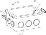
接线盒是用于安装电气线缆的塑料载体,如图12所示,其包括呈仅一端开口结构的盒体、安装于盒体的螺母和插片,盒体的内壁两侧分别设置有柱梁,柱梁顶端设置有用于容纳螺母的顶槽,盒体两侧贯穿开设有供插片插入的通槽,插片穿过通槽后压合于螺母之上,插片垂直设置有卡接板,盒体的外侧壁设置有供卡接板卡接固定的卡接槽,螺母和插片贯穿开设有中心通孔。The junction box is a plastic carrier used to install electrical cables. As shown in Figure 12, it includes a box body with only one end open, a nut and an insert mounted on the box body, and columns are respectively provided on both sides of the inner wall of the box body. The top of the beam, the column beam is provided with a top groove for accommodating the nut, and the two sides of the box body are provided with through grooves for inserting the inserts. The inserts pass through the through grooves and are pressed onto the nuts. The outer side wall of the box body is provided with a clamping groove for clamping and fixing the clamping plate, and a central through hole is formed through the nut and the insert.
上述接线盒在传统车间装配时,需要由工人将螺母放置于顶槽,再由工人将插片插入通槽,并按压卡接板使其卡接固定于卡接槽,从而由被固定的插片压紧限制螺母。When the above-mentioned junction box is assembled in a traditional workshop, the worker needs to place the nut in the top slot, and then the worker inserts the insert into the through slot, and presses the snap plate to make it snap and fix in the snap slot, so that the fixed insert plate to compress the limit nut.
传统的装配需要由人工完成,存在费时费力、生产效率低下、且生产成本高的问题;因此需要提出一种新的方案来解决这个问题。The traditional assembly needs to be done manually, which is time-consuming, labor-intensive, low in production efficiency, and high in production cost; therefore, a new solution needs to be proposed to solve this problem.
发明内容SUMMARY OF THE INVENTION
针对现有技术存在的不足,本发明的目的在于提供一种接线盒插片自动安装机,工人仅需负责放置盒体,即可自动完成螺母的放置、插片的安装以及卸料,有效提高生产效率,降低人工成本。In view of the deficiencies in the prior art, the purpose of the present invention is to provide an automatic installation machine for junction box inserts. The worker only needs to be responsible for placing the box body, and can automatically complete the placement of nuts, the installation of inserts, and the unloading, effectively improving Production efficiency, reduce labor costs.
本发明的上述技术目的是通过以下技术方案得以实现的:一种接线盒插片自动安装机,包括中央控制器、送盒装置、垂直于接线盒输送方向且将接线盒推送至加工指定位置的接线盒进给机构、用于将螺母安装到接线盒上的螺母安装机构、用于将插片安装到接线盒上的插片安装机构、位于螺母安装机构一侧且用于输送螺母的螺母震动输送装置,以及位于插片安装机构侧部且用于输送插片的插片震动输送装置;The above-mentioned technical purpose of the present invention is achieved through the following technical solutions: an automatic junction box inserting machine, comprising a central controller, a box feeding device, a junction box that is perpendicular to the conveying direction of the junction box and pushes the junction box to a designated position for processing Junction box feed mechanism, Nut mounting mechanism for mounting nuts to junction boxes, Blade mounting mechanism for mounting tabs to junction boxes, Nut vibration on the side of the nut mounting mechanism and conveying nuts A conveying device, and a vibrating conveying device for inserting inserts located at the side of the inserting insert installation mechanism and used for conveying inserting inserts;
所述螺母安装机构包括与螺母震动输送装置连接的螺母排列座、位于螺母排列座上方的X-Y向转送组件,以及固定于X-Y向转送组件上的取片组件;The nut installation mechanism includes a nut arrangement seat connected with the nut vibration conveying device, an X-Y direction transfer assembly located above the nut array seat, and a film pickup assembly fixed on the X-Y direction transfer assembly;
所述插片安装机构包括垂直于插片输送方向设置的插片推缸以及设置于插片推缸活塞杆端的推块;所述推块的内部具有一空腔,该空腔连通有抽气设备;所述推块的前端面上设置有与空腔连通的通孔。The insert installation mechanism includes an insert push cylinder arranged perpendicular to the insert sheet conveying direction and a push block arranged at the end of the piston rod of the insert push cylinder; the inside of the push block has a cavity, and the cavity is connected with an air extraction device ; The front end surface of the push block is provided with a through hole communicating with the cavity.
通过采用上述技术方案,本申请在正常工作时,由工人将盒体呈开口向上放置于送盒装置,从而由送盒装置将盒体送入到接线盒进给机构处;再由接线盒进给机构将接线盒送到加工指定位置,传感器检测接线盒到达位置,发出指令给中央控制器,中央控制器接受到信号控制螺母安装机构工作,螺母震动输送装置将螺母输送进来,取片组件取到螺母并且安装到接线盒上;螺母安装机构回位,接线盒进给机构继续工作,安装好螺母的接线盒进入到下一个工位,中央控制器控制插片安装机构工作,插片震动输送装置将插片输送进来,抽气设备抽气将插片吸住在推块的前端面上,再由推缸将推块推送,将插片安装到接线盒上;如此循环工作。By adopting the above technical solution, when the application is working normally, the worker places the box body on the box feeding device with the opening upward, so that the box body is sent to the junction box feeding mechanism by the box feeding device; Send the junction box to the designated position for processing, the sensor detects that the junction box reaches the position, and sends an instruction to the central controller. The central controller receives the signal and controls the nut installation mechanism to work. To the nut and install it on the junction box; the nut installation mechanism returns, the junction box feeding mechanism continues to work, the junction box with the nut installed enters the next station, the central controller controls the blade installation mechanism to work, and the blade is vibrated and conveyed. The device transports the inserts in, the air suction equipment sucks the inserts on the front end surface of the push block, and then the push cylinder pushes the push block to install the inserts on the junction box; this cycle works.
本发明进一步设置为:所述送盒装置包括直线轨道、设置于直线轨道底部的摩擦皮带,以及用于驱动摩擦皮带的驱动电机;沿接线盒的输送方向,在其尾端设置有支撑竖板,所述支撑竖板贯穿开设有仅能供一个盒体穿过的洞口,所述洞口的上方设置有隔断气缸,所述隔断气缸的活塞杆端设置有隔断块,所述隔断块的下边沿设置有切断斜边。The present invention is further provided as follows: the box feeding device includes a linear track, a friction belt arranged at the bottom of the linear track, and a driving motor for driving the friction belt; along the conveying direction of the junction box, a supporting vertical plate is arranged at the rear end thereof The support vertical plate is provided with a hole through which only one box can pass through, a partition cylinder is arranged above the hole, and a partition block is arranged on the piston rod end of the partition cylinder, and the lower edge of the partition block is provided. Provided with cut off beveled edge.
其中,所述接线盒进给机构包括承载板、设置于承载板两侧的限制块,以及固定于两个限制块一端的前推气缸。Wherein, the junction box feeding mechanism includes a carrier plate, limit blocks arranged on both sides of the carrier board, and a forward push cylinder fixed on one end of the two limit blocks.
通过采用上述技术方案,位于直线轨道最前方的盒体穿过洞口进入排列机构后,由隔断气缸推动隔断块下切,一方面由切断斜边切断相邻盒体的连接,另一方面由隔断块隔离最前方的盒体与后方盒体,从而避免前推气缸在推动盒体过程中,后一个盒体进入到接线盒进给机构。By adopting the above technical solution, after the box body located at the front of the linear track enters the arrangement mechanism through the hole, the partition block is pushed by the partition cylinder to cut down. Isolate the box body at the front and the rear box body, so as to prevent the latter box body from entering the junction box feeding mechanism during the process of pushing the box body by the forward push cylinder.
本发明进一步设置为:位于接线盒加工指定位置的正上方设置有拱形架,所述X-Y向转送组件安装于拱形架的一侧,所述拱形架的另一侧设置有定位组件,所述定位组件包括固定于拱形架的定位气缸,以及设置于定位气缸输出轴段的定位块,所述定位块呈梯形台体,且其小端面处于下方。The present invention is further provided as follows: an arched frame is arranged just above the designated processing position of the junction box, the X-Y direction transfer assembly is installed on one side of the arched frame, and the other side of the arched frame is provided with a positioning assembly, The positioning assembly includes a positioning cylinder fixed on the arched frame, and a positioning block arranged on the output shaft section of the positioning cylinder.
通过采用上述技术方案,增设拱形架为X-Y向转送组件和定位组件提供一个安装位置;当盒体被推送至定位组件正下方时,由定位气缸驱动定位块下移,定位块在下移的过程中逐步由对应盒体的上端面开口嵌入,从而利用定位块的四侧斜壁推动盒体移动,实现其精准定位,进而确保盒体的通槽对准于待安装的插片。By adopting the above technical solution, an additional arch frame provides an installation position for the X-Y transfer assembly and the positioning assembly; when the box body is pushed directly below the positioning assembly, the positioning block is driven by the positioning cylinder to move down, and the positioning block is in the process of moving down. It is gradually embedded in the upper end face of the corresponding box body, so that the box body is moved by the four side inclined walls of the positioning block to achieve its precise positioning, thereby ensuring that the through grooves of the box body are aligned with the inserts to be installed.
本发明进一步设置为:所述X-Y向转送组件包括滑移连接于拱形架的X向滑块、用于驱动X向滑块的X向气缸、固定于X向滑块的Y向气缸,以及固定于Y向气缸活塞杆的Y向升降块,所述取片组件安装于Y向升降块。The present invention is further provided as follows: the X-Y direction transfer assembly includes an X-direction slider slidably connected to the arched frame, an X-direction air cylinder for driving the X-direction slider, a Y-direction air cylinder fixed to the X-direction slider, and The Y-direction lifting block is fixed on the piston rod of the Y-direction cylinder, and the film pick-up assembly is installed on the Y-direction lifting block.
通过采用上述技术方案,由X向气缸驱动X向滑块沿拱形架滑动,并由Y向气缸驱动Y向升降块纵向位移,从而仅需将取片组件安装于Y向升降块,即可由X-Y向转送组件实现对取片组件的双轴向驱动。By adopting the above technical solution, the X-direction slider is driven by the X-direction cylinder to slide along the arched frame, and the Y-direction lifting block is driven to move longitudinally by the Y-direction cylinder. The X-Y direction transfer assembly realizes biaxial driving of the film pickup assembly.
本发明进一步设置为:所述取片组件包括分别固定于Y向升降块的取片气缸和取片块以及位于取片气缸与取片块之间且由取片气缸控制其上下运动的活动块,所述取片块的内部设置有取片空腔,所述取片空腔连通有负压装置,所述取片块的底部开设有与取片空腔连通的取片气孔,所述取片气孔中设置有取片插针,所述取片插针与活动块连接。The present invention is further provided as follows: the film removal assembly includes a film removal cylinder and a film removal block respectively fixed to the Y-direction lifting block, and a movable block located between the film removal cylinder and the film removal block and controlled by the film removal cylinder to move up and down. , the inside of the film removal block is provided with a film removal cavity, the film removal cavity is communicated with a negative pressure device, and the bottom of the film removal block is provided with a film removal air hole that communicates with the film removal cavity. The film air hole is provided with a film removal pin, and the film removal pin is connected with the movable block.
通过采用上述技术方案,取片组件在正常工作时,由X-Y向转送组件驱动取片组件的取片块贴合于螺母排列座的上表面,此状态下,两个取片插针分别对准于相应螺母的中心通孔,取片块贴合螺母表面,负压装置运行,取片块通过取片气孔吸取螺母;再取片气缸推动两个取片插针下移,直至穿过取片通孔并插入于相应螺母的中心通孔,从而利用摩擦力完成取片插针与螺母的连接,由X-Y向转送组件驱动取片组件直至两个螺母分别进入相应盒体的顶槽。By adopting the above technical solution, when the retrieving assembly is in normal operation, the retrieving block of the retrieving assembly is driven by the X-Y direction transfer assembly to be attached to the upper surface of the nut arrangement seat. In this state, the two retrieving pins are aligned with each other. In the center through hole of the corresponding nut, the piece taking block is attached to the surface of the nut, and the negative pressure device operates, and the piece taking block sucks the nut through the taking piece air hole; then the piece taking cylinder pushes the two taking piece pins down until they pass through the taking piece. The through-hole is inserted into the central through-hole of the corresponding nut, so that the connection between the retrieving pin and the nut is completed by frictional force.
本发明进一步设置为:螺母震动输送装置包括螺母震动盘、螺母排列座,所述螺母震动盘上连接有螺母细轨,所述螺母排列座的上表面上设置有排列长槽,所述螺母细轨与排列长槽连通;The present invention is further provided as follows: the nut vibration conveying device comprises a nut vibration plate and a nut arrangement seat, the nut vibration plate is connected with a nut thin rail, an arrangement long groove is arranged on the upper surface of the nut arrangement seat, and the nut thin The rail is communicated with the arrangement long groove;
所述排列长槽的另一端设置有供单一螺母完整露出的缺口,相对于缺口的正前方处设置有检测螺母到达位置的信号检测装置。The other end of the long arrangement slot is provided with a notch for the single nut to be completely exposed, and a signal detection device for detecting the arrival position of the nut is arranged in front of the notch.
本发明进一步设置为:所述插片震动输送装置包括插片震动盘和设置于插片震动盘上的插片细轨,所述插片细轨连接有插片导轨,The present invention is further provided as follows: the inserting sheet vibration conveying device comprises an inserting sheet vibrating disc and an inserting sheet thin rail arranged on the inserting sheet vibrating disc, and the inserting sheet thin rail is connected with the inserting sheet guide rail,
所述插片细轨和插片导轨均设置有用于容纳卡接板的竖直槽,所述插片细轨和插片导轨设置有支撑插片的水平面。The thin insert rails and the insert guide rails are both provided with vertical grooves for accommodating the clip plates, and the insert thin rails and the insert guide rails are provided with horizontal planes for supporting the insert plates.
通过采用上述技术方案,插片震动输送装置利用插片细轨连接插片导轨,从而实现由插片震动输送装置为插片导轨供应插片的技术要求;插片细轨和插片导轨利用竖直槽容纳卡接板,并由水平面支撑插片,从而确保插片的送料稳定性。By adopting the above-mentioned technical solution, the inserting sheet vibration conveying device uses the inserting thin rail to connect the inserting guide rail, so as to realize the technical requirement of supplying the inserting sheet by the inserting sheet vibration conveying device for the inserting guide rail; the inserting thin rail and the inserting guide rail utilize vertical The straight slot accommodates the clip board and supports the inserts by a horizontal plane, thus ensuring the feeding stability of the inserts.
本发明进一步设置为:所述限制块上设置有供推块做伸缩运动的通道,位于限制块的上内侧端面上且位于通道的出口处铰接有限位块。The present invention is further provided as follows: the limiting block is provided with a channel for the push block to perform telescopic motion, and the limiting block is hinged on the upper inner end face of the limiting block and at the outlet of the channel.
本发明进一步设置为:平行于所述插片导轨的方向设置有插片推送气缸,所述插片推送气缸的活塞杆端设置有插片推送块,所述插片推送块两端转动连接有转动块,所述转动块抵接于水平面,其具有竖直推面和翘起斜面,所述竖直推面朝向排列机构,所述翘起斜面朝向插片细轨。The present invention is further provided as follows: an inserting piece pushing cylinder is arranged parallel to the direction of the inserting piece guide rail; A rotating block, the rotating block abuts on a horizontal plane, and has a vertical pushing surface and a tilting inclined surface, the vertical pushing surface faces the arranging mechanism, and the tilting tilting surface faces the thin insert rail.
通过采用上述技术方案,插片和卡接板进入到插片导轨后,需要前进一段距离时,由插片推送气缸推动插片推送块前进,插片推送块在前进过程中转动块的竖直推面施力于插片,从而推动插片和卡接板前进一段距离;完成一段距离后插片推送气缸拉动插片推送块复位,在复位时转动块的翘起斜面抵接于后一个插片,从而在分力的作用下推动转动块向上翘起,进而避免后方插片影响插片推送块的复位。By adopting the above technical solution, after the insert piece and the clip board enter the insert piece guide rail, when they need to advance a certain distance, the insert piece push cylinder pushes the insert piece push block forward, and the insert piece push block rotates the vertical direction of the block during the advance process. The push surface exerts force on the insert piece, thereby pushing the insert piece and the clamping plate forward for a certain distance; after a certain distance is completed, the insert piece push cylinder pulls the insert piece push block to reset, and the tilted surface of the rotating block abuts against the latter insert during reset. Therefore, under the action of the component force, the rotating block is pushed up, so as to prevent the rear insert from affecting the reset of the insert push block.
综上所述,本发明具有以下有益效果:仅需负责放置盒体,即可自动完成螺母的放置、插片的安装以及卸料,有效提高生产效率,降低人工成本。由隔断气缸推动隔断块下切,一方面由切断斜边切断相邻盒体的连接,另一方面由隔断块隔离最前方的盒体与后方盒体;利用定位块的四侧斜壁推动盒体移动,实现其精准定位,从而确保盒体的通槽对准于待安装的插片;利用取片插针和吸住螺母的方式,相比于传统的夹爪送料,更适用于体积较小的螺母;螺母排列座通过两个排列长槽实现对螺母的有序排列;利用两个螺母细轨连接两个排列长槽和螺母震动输送装置,从而实现由螺母震动输送装置为螺母排列座供应螺母的技术要求;排列长槽的端部设置缺口供最前方的螺母完整露出,从而确保取片组件顺利插取螺母;插片细轨和插片导轨利用竖直槽容纳插片,并由水平面支撑插片,从而确保插片的送料稳定性;插片通过导轨输送至通道的出口处,通过定位片定位,确保插片输送位置的精确性;推块吸住待安装的插片,定位片在插片被推入接线盒的槽的过程中,防止插片发生倾倒或者翘起,导致其位置偏移,无法完成安装的工作。To sum up, the present invention has the following beneficial effects: only for placing the box body, the nut placement, the inserting piece installation and the unloading can be automatically completed, thereby effectively improving production efficiency and reducing labor costs. The partition block is pushed down by the partition cylinder. On the one hand, the connection between the adjacent boxes is cut off by the cutting oblique edge. On the other hand, the frontmost box and the rear box are separated by the partition block. Move to achieve its precise positioning, so as to ensure that the through groove of the box is aligned with the insert to be installed; the method of taking the insert pin and sucking the nut is more suitable for smaller volumes than the traditional gripper feeding. The nut arrangement seat realizes the orderly arrangement of the nuts through two arrangement long grooves; the two long arrangement grooves and the nut vibration conveying device are connected by two nut thin rails, so as to realize the supply of the nut array seat by the nut vibration conveying device The technical requirements of the nut; the end of the long slot is arranged with a gap so that the front nut can be completely exposed, so as to ensure the smooth insertion of the nut; Support the insert to ensure the feeding stability of the insert; the insert is transported to the exit of the channel through the guide rail, and positioned by the positioning piece to ensure the accuracy of the delivery position of the insert; the push block sucks the insert to be installed, positioning the piece When the insert is pushed into the slot of the junction box, the insert is prevented from being tipped or lifted, resulting in its position being shifted, and the installation work cannot be completed.
附图说明Description of drawings
图1为实施例一的整体结构示意图;1 is a schematic diagram of the overall structure of
图2为实施例一另一视角的整体结构示意图;2 is a schematic diagram of the overall structure from another perspective of
图3为实施例一的俯视图;3 is a top view of the first embodiment;
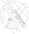
图4为图2的A部放大示意图,主要表示隔断块和洞口的配合关系;Fig. 4 is the enlarged schematic diagram of the A part of Fig. 2, mainly showing the cooperation relationship between the partition block and the opening;
图5为实施例一隐藏送盒装置后的结构示意图;5 is a schematic structural diagram of the hidden box feeding device in
图6为实施例一定位组件与盒体的配合关系图,为便于表示该附图进行有局部剖视处理;FIG. 6 is a diagram of the matching relationship between the positioning assembly and the box body according to the first embodiment, and a partial cross-sectional process is carried out to facilitate the representation of the drawing;
图7为实施例一X-Y向转送组件的结构示意图;7 is a schematic structural diagram of an X-Y direction transfer assembly in
图8为实施例一螺母排列座的结构示意图;8 is a schematic structural diagram of a nut arrangement seat in
图9为实施例一插片震动座、排列机构以及插片安装机构三者的配合关系图;FIG. 9 is a diagram showing the cooperation relationship of the insert vibration seat, the arrangement mechanism and the insert mounting mechanism according to the first embodiment;
图10为图9的B部放大图,主要表示露出槽处的结构;Fig. 10 is an enlarged view of part B of Fig. 9, mainly showing the structure at the exposed groove;
图11为实施例一插片推送块的结构示意图;FIG. 11 is a schematic structural diagram of a chip pushing block in
图12为所需装配的接线盒的结构示意图;Figure 12 is a schematic structural diagram of a junction box to be assembled;
图13为实施例一取片块的内部结构示意图;Figure 13 is a schematic diagram of the internal structure of the film fetching block in the first embodiment;
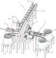
图14为实施例二的结构示意图;14 is a schematic structural diagram of
附图说明:1、送盒装置;11、直线轨道;12、摩擦皮带;13、驱动电机;14、支撑竖板;15、洞口;16、隔断气缸;17、隔断块;18、切断斜边;Description of drawings: 1. Box feeding device; 11. Linear track; 12. Friction belt; 13. Driving motor; 14. Supporting vertical plate; 15. Opening; ;
2、接线盒进给机构;21、承载板;22、限制块;23、前推气缸;24、坠落口;25、倾斜滑板;3、螺母震动输送装置;31、螺母排列座;32、螺母震动盘;35、螺母细轨;311、排列长槽;312、缺口;313、信号检测装置;33、螺母安装机构; 331、X向滑块;332、X向气缸;333、Y向气缸;334、Y向升降块;335、滑轨;34、取片组件;341、活动块;342、取片气缸;343、取片插针;344、取片气孔;345、取片块;4、插片安装机构;41、插片导轨;42、插片推缸;43、推块;44、通道;45、限位块;5、插片推送气缸;51、插片推送块;52、转动块;53、竖直推面;54、翘起斜面;6、插片震动输送装置;61、插片细轨;62、竖直槽;63、水平面;64、插片震动盘;7、定位组件;71、拱形架;72、定位气缸;73、定位块;74、楔形块;75、分力斜边;8、中央控制器;9、接线盒;91、盒体;92、螺母;93、插片;94、顶槽;95、中心通孔。2. Junction box feeding mechanism; 21. Loading plate; 22. Limit block; 23. Forward push cylinder; 24. Falling port; 25. Inclined slide plate; 3. Nut vibration conveying device; 31. Nut arrangement seat; 32. Nut Vibration plate; 35, nut thin rail; 311, arrangement of long grooves; 312, notch; 313, signal detection device; 33, nut installation mechanism; 331, X-direction slider; 332, X-direction cylinder; 333, Y-direction cylinder; 334, Y-direction lifting block; 335, slide rail; 34, film removal assembly; 341, movable block; 342, film removal cylinder; 343, film removal pin; 344, film removal air hole; 345, film removal block; 4, Insert installation mechanism; 41, Insert guide rail; 42, Insert push cylinder; 43, Push block; 44, Channel; 45, Limit block; 5, Insert push cylinder; 51, Insert push block; 52, Rotation block; 53, vertical push surface; 54, tilted inclined surface; 6, insert vibration conveying device; 61, insert thin rail; 62, vertical groove; 63, horizontal plane; 64, insert vibration plate; 7, positioning Components; 71, arch frame; 72, positioning cylinder; 73, positioning block; 74, wedge block; 75, component bevel; 8, central controller; 9, junction box; 91, box body; 92, nut; 93. Insert; 94. Top slot; 95. Center through hole.
具体实施方式Detailed ways
以下结合附图对本发明作进一步详细说明。The present invention will be further described in detail below with reference to the accompanying drawings.
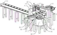
实施例一:接线盒插片自动安装机,如图1、图2、图3所示,包括中央控制器8、送盒装置1、垂直于线盒输送方向且将接线盒9推送至加工指定位置的接线盒进给机构2、用于将螺母92安装到接线盒9上的螺母安装机构33、用于将插片93安装到接线盒9上的插片安装机构4、位于螺母安装机构33一侧且用于输送螺母92的螺母震动输送装置3,以及位于插片安装机构4侧部且用于输送插片93的插片震动输送装置6;中央控制器8通过导线、信号传感器与各个机构连接,并且控制各个机构工作。Embodiment 1: The junction box insert automatic installation machine, as shown in Figure 1, Figure 2, Figure 3, includes a
见图3,送盒装置1包括截面呈U形的直线轨道11、绕设于直线轨道11底部的摩擦皮带12,以及用于驱动摩擦皮带12的驱动电机13。沿接线盒9的输送方向,在其尾端设置有支撑竖板14,支撑竖板14贯穿开设有仅能供一个盒体91穿过的洞口15,洞口15的上方设置有隔断气缸16,隔断气缸16的活塞杆端设置有隔断块17,隔断块17的下边沿设置有切断斜边18。Referring to FIG. 3 , the
其中,接线盒进给机构2包括承载板21、设置于承载板21两侧的限制块22,以及固定于两个限制块22一端的前推气缸23。The junction
见图3,螺母安装机构33包括与螺母震动输送装置3连接的螺母排列座31、位于螺母排列座31上方的X-Y向转送组件,以及固定于X-Y向转送组件上的取片组件34。3, the
见图3和图8,螺母震动输送装置3包括螺母震动盘32、螺母排列座31,螺母震动盘32上连接有螺母细轨33,螺母排列座31的上表面上设置有排列长槽311,螺母细轨33与排列长槽311各自分别有两条,每条螺母细轨33与各自的排列长槽311连通,组成完整的输送导轨。排列长槽311的另一端设置有供单一螺母92完整露出的缺口312,相对于缺口312的正前方处设置有检测螺母92到达位置的信号检测装置313。信号检测装置313检测到螺母92被输送到指定位置,则发出信号给中央控制器8,中央控制器8收到则控制螺母震动盘32暂停工作。3 and 8, the nut
见图7,位于接线盒9加工指定位置的正上方设置有拱形架71,X-Y向转送组件安装于拱形架71的一侧,拱形架71的另一侧设置有定位组件7。7 , an
X-Y向转送组件包括X向滑块 331、用于驱动X向滑块 331的X向气缸332、固定于X向滑块 331上的Y向气缸333以及固定于Y向气缸333活塞杆的Y向升降块334。取片组件34安装于Y向升降块334上。拱形架71的一侧上安装有滑轨335,X向滑块 331安装在滑轨335上,X向气缸332控制X向滑块 331做滑移运功。The X-Y direction transfer assembly includes an
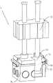
见图7和图13,取片组件34包括分别固定于Y向升降块334的取片气缸342和取片块345以及位于取片气缸342与取片块345之间且由取片气缸342控制其上下运动的活动块341,取片块345的内部设置有取片空腔,取片空腔连通有负压装置,取片块345的底部开设有与取片空腔连通的取片气孔344,取片气孔344设置有两个,每个取片气孔344中设置有一根取片插针343,每根取片插针343都与活动块341连接。7 and 13 , the film-taking
取片过程:Y向升降块334带动取片块下降,取片块压在螺母92上,负压装置抽气,将螺母92吸住,固定住螺母92;然后取片气缸342控制活动块341下降,两根取片插针343从取片气孔344探出,正确的插入螺母92的中心通孔95中,取片气缸342控制活动块341上升,将螺母92带离,从而取得螺母92。The film removal process: the Y-
安装螺母92过程:取得螺母92后,由X-Y向转送组件驱动取片组件34移动到相应盒体91的正上方,Y向气缸333控制Y向升降块334下降,取片块345压在盒体91上,对准盒体91的顶槽94,取片气缸342控制取片插针343将螺母92放入顶槽94内,然后取片插针343复位,Y向气缸333控制Y向升降块334上升、复位。The process of installing the nut 92: After the
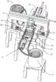
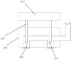
见图6,定位组件7包括固定于拱形架71的定位气缸72,以及设置于定位气缸72输出轴段的定位块73,定位块73呈梯形台体,且其小端面处于下方。6, the
参考图9和图10,插片震动输送装置6包括插片震动盘64和设置于插片震动盘64上的插片细轨61,所述插片细轨61连接有插片导轨41,插片细轨61和插片导轨41均设置有用于容纳插片的竖直槽62,插片细轨61和插片导轨41设置有支撑插片93的水平面63。Referring to FIGS. 9 and 10 , the insert
插片安装机构4包括垂直于插片93输送方向设置的插片推缸42以及固定于插片推缸42活塞杆端的推块43;推块43的内部具有一空腔,该空腔连通有抽气设备;推块43的前端面上设置有与空腔连通的通孔。推块43具有吸住插片93的能力。The
限制块22有一对,沿接线盒9进给的方向对称设置;插片安装机构4也有一对,插片安装机构4位于限制块22的外侧。每块限制块22上均设置有供推块43做伸缩运动的通道44,位于限制块22的上内侧端面上且位于通道44的出口处铰接有限位块45。There are a pair of restricting
为避免在安装插片93时螺母92发生跳动,如图6所示,定位块73的两侧正对螺母92滑移连接有楔形块74,楔形块74下端面外侧设置有分力斜边75;当定位块73压紧于盒体91时,楔形块74也刚好接触到接线盒9的顶槽94,当插片93在插入的过程中,插片93的上表面边沿抵接于分力斜边75,从而推动楔形块74上移,楔形块74移动距离等于或者稍微大于插片93上表面的厚度。定位块73升起后,楔形块74在弹力的作用下复位。In order to prevent the
本机器在正常工作时,由工人将盒体91呈开口向上放置于直线轨道11,从而由驱动电机13驱动的摩擦皮带12利用摩擦力推动盒体91沿直线轨道11前进;当盒体91由直线轨道11进入到接线盒进给机构2时,由前推气缸23推动盒体91沿两个限制块22的长度方向前移一段距离(前移距离为单个盒体91的宽度),从而实现对多个盒体91的直线排列和间歇式推进;其一盒体91被推进到X-Y向转送组件的正下方,与上述过程同步进行的是,螺母震动输送装置3利用振动力推送螺母92进入并排列于螺母排列座31,X-Y向转送组件驱动取片组件34进行取片以及安装螺母92。When the machine is working normally, the worker places the
安装好螺母92的盒体91被推进到下一个工位,与上述过程同步进行的是,插片震动输送装置6利用震动力推送插片93进入插片导轨41,并沿插片导轨41移动到通道44的出口处,并且通过限位块45实现定位;使插片93正确到达指定位置。The
插片推缸42驱动推块43,抽气设备也工作,从而使推块43吸住插片93,并推动插片93插入接线盒9的通槽;完成插片93的安装后插片推缸42拉动推块43复位;完成插片93安装的盒体91被送出;综上所述,本申请工人仅需负责放置盒体91,即可自动完成螺母92的放置、插片93的安装以及卸料,有效提高生产效率,降低人工成本。The
为提高盒体91的生产效率,一般会通过多个同步进行注塑的方式进行生产,这样的方式会导致相邻的两个盒体91可能存在连接,为此如图2、图4所示,直线轨道11与排列机构连接端螺栓固定有支撑竖板14,支撑竖板14水平贯穿开设有仅能供一个盒体91穿过的洞口15,洞口15的上方螺栓固定有隔断气缸16,隔断气缸16的活塞杆端固定有隔断块17,隔断块17的下边沿设置有切断斜边18;位于直线轨道11最前方的盒体91穿过洞口15进入排列机构后,由隔断气缸16推动隔断块17下切,一方面由切断斜边18切断相邻盒体91的连接,另一方面由隔断块17隔离最前方的盒体91与后方盒体91,从而避免前推气缸23在推动盒体91沿排列机构前进的过程中,后一个盒体91进入到排列机构。In order to improve the production efficiency of the
为便于卸料,如图5所示,在接线盒9加工位置的后方设置有坠落口24,坠落口24正下方固定安装有倾斜滑板25,从而完成插片93安装的盒体91被推送到坠落口24处,在重力的作用下经坠落口24掉出排列机构,并沿倾斜滑板25滑动至工人所需的卸料位点。也可以设置条输送带,将加工好的接线盒9直接输送出去。In order to facilitate unloading, as shown in FIG. 5, a
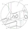
为定位待安装插片93的盒体91,如图5、图6所示,在接线盒加工工位的上方固定安装有拱形架71,X-Y向转送组件安装于拱形架71的一侧,拱形架71的另一侧设置有定位组件7,定位组件7包括固定于拱形架71的定位气缸72,以及固定于定位气缸72输出轴段的定位块73,定位块73呈梯形台体,且其小端面处于下方;当盒体91被推送至定位组件7的正下方时,由定位气缸72驱动定位块73下移,定位块73在下移的过程中逐步由对应盒体91的上端面开口嵌入,从而利用定位块73的四侧斜壁推动盒体91移动,实现其精准定位,进而确保盒体91的通槽对准于待安装的插片93。In order to locate the
本申请通过如下方式推动插片93沿插片导轨41间歇前进,如图9、图11所示,平行于插片导轨41设置有插片推送气缸5,插片推送气缸5的活塞杆端设置有插片推送块51,插片推送块51的两端转动连接有转动块52,转动块52抵接于水平面63,其具有竖直推面53和翘起斜面54,竖直推面53朝向排列机构,翘起斜面54朝向插片细轨61;插片93和卡接板进入到插片导轨41后,需要前进一段距离时,由插片推送气缸5推动插片推送块51前进,插片推送块51在前进过程中转动块52的竖直推面53施力于插片93,从而推动插片93和卡接板前进一段距离;完成一段距离的推送后插片推送气缸5拉动插片推送块51复位,在复位时转动块52的翘起斜面54抵接于后一个插片93,从而在分力的作用下推动转动块52向上翘起,进而避免后方插片93影响插片推送块51的复位。In the present application, the
实施例二:本实施例与实施例一的区别之处在于,见图14,插片震动输送装置6的具体数量为两个,且两个插片震动输送装置6分别位于定位机构的两侧,从而避免排列机构前端出线阻挡,进而赋予本申请于排列机构前端设置码垛机的空间。Embodiment 2: The difference between this embodiment and
具体实施例仅仅是对本发明的解释,其并不是对本发明的限制,本领域技术人员在阅读完本说明书后可以根据需要对本实施例做出没有创造性贡献的修改,但只要在本发明的权利要求范围内都受到专利法的保护。The specific embodiment is only an explanation of the present invention, and it is not a limitation of the present invention. Those skilled in the art can make modifications without creative contribution to the present embodiment as needed after reading this specification, but only in the claims of the present invention are protected by patent law.
Claims (10)
Priority Applications (1)
| Application Number | Priority Date | Filing Date | Title |
|---|---|---|---|
| CN202010960259.6ACN112025271B (en) | 2020-09-14 | 2020-09-14 | Junction box plug automatic installation machine |
Applications Claiming Priority (1)
| Application Number | Priority Date | Filing Date | Title |
|---|---|---|---|
| CN202010960259.6ACN112025271B (en) | 2020-09-14 | 2020-09-14 | Junction box plug automatic installation machine |
Publications (2)
| Publication Number | Publication Date |
|---|---|
| CN112025271Atrue CN112025271A (en) | 2020-12-04 |
| CN112025271B CN112025271B (en) | 2024-11-05 |
Family
ID=73589757
Family Applications (1)
| Application Number | Title | Priority Date | Filing Date |
|---|---|---|---|
| CN202010960259.6AActiveCN112025271B (en) | 2020-09-14 | 2020-09-14 | Junction box plug automatic installation machine |
Country Status (1)
| Country | Link |
|---|---|
| CN (1) | CN112025271B (en) |
Cited By (3)
| Publication number | Priority date | Publication date | Assignee | Title |
|---|---|---|---|---|
| CN113263302A (en)* | 2021-01-29 | 2021-08-17 | 嘉兴云聪自动化科技有限公司 | Automatic pin machine of big dipper navigation antenna |
| CN113979080A (en)* | 2021-11-17 | 2022-01-28 | 深圳市宏拓伟业科技有限公司 | Intelligent material feeding unit that company's tape insertion piece was used |
| WO2024065619A1 (en)* | 2022-09-30 | 2024-04-04 | 安徽突飞电器有限公司 | Automatic assembly apparatus for multi-clamping-position concealed bottom box, and process therefor |
Citations (16)
| Publication number | Priority date | Publication date | Assignee | Title |
|---|---|---|---|---|
| JP2007160477A (en)* | 2005-12-15 | 2007-06-28 | Aisin Aw Co Ltd | Ring member aligning device |
| US20090084571A1 (en)* | 2007-09-27 | 2009-04-02 | Phillips Bruce G | Method and apparatus for pre-fab wiring |
| CN201988645U (en)* | 2010-10-20 | 2011-09-28 | 上海华普汽车有限公司 | High-precision tipping machine positioning mechanism |
| CN202742407U (en)* | 2012-08-03 | 2013-02-20 | 厦门铭轩精密机械有限公司 | Air cylinder cutter |
| CN103692215A (en)* | 2013-12-30 | 2014-04-02 | 佛山市亿强电子有限公司 | Automatic assembling machine for electronic heads of piezoelectric ceramic igniters |
| CN204800267U (en)* | 2015-05-15 | 2015-11-25 | 深圳市虎雅科技有限公司 | Automatic kludge of terminal |
| CN106335158A (en)* | 2016-08-30 | 2017-01-18 | 德阳致达精密电子有限公司 | Automatic continuous injection molding system for packaging 3C electronic chips |
| CN206388275U (en)* | 2017-01-16 | 2017-08-08 | 河北汇金机电股份有限公司 | Shipment device for automatic selling equipment |
| CN208662965U (en)* | 2018-01-24 | 2019-03-29 | 宁波禹泰自动化科技有限公司 | A kind of terminal box feeding machanism and its assembly machine |
| CN109638605A (en)* | 2018-12-22 | 2019-04-16 | 深圳市阿尓法智慧科技有限公司 | A kind of plug assembly automatic assembly equipment for electric heater |
| US20190115674A1 (en)* | 2017-10-12 | 2019-04-18 | Hubbell Incorporated | Set screw connector |
| CN109664088A (en)* | 2018-12-29 | 2019-04-23 | 嘉兴汉羿文化传播有限公司 | A kind of sleeve column feeding press-loading device |
| CN209774816U (en)* | 2019-04-19 | 2019-12-13 | 绵阳裕达电子科技有限公司 | Base station in parting process of injection molding shell of DIP device |
| CN210116110U (en)* | 2019-06-24 | 2020-02-28 | 卓研精密工业(苏州)有限公司 | Nut moving mechanism based on negative pressure air suction needle |
| CN211365115U (en)* | 2019-12-06 | 2020-08-28 | 河南中烟工业有限责任公司 | A cigarette stabilizing device for a cigarette box sealing machine |
| CN212311357U (en)* | 2020-09-14 | 2021-01-08 | 浙江容德管业股份有限公司 | Automatic assembling machine for terminal box inserting pieces |
- 2020
- 2020-09-14CNCN202010960259.6Apatent/CN112025271B/enactiveActive
Patent Citations (16)
| Publication number | Priority date | Publication date | Assignee | Title |
|---|---|---|---|---|
| JP2007160477A (en)* | 2005-12-15 | 2007-06-28 | Aisin Aw Co Ltd | Ring member aligning device |
| US20090084571A1 (en)* | 2007-09-27 | 2009-04-02 | Phillips Bruce G | Method and apparatus for pre-fab wiring |
| CN201988645U (en)* | 2010-10-20 | 2011-09-28 | 上海华普汽车有限公司 | High-precision tipping machine positioning mechanism |
| CN202742407U (en)* | 2012-08-03 | 2013-02-20 | 厦门铭轩精密机械有限公司 | Air cylinder cutter |
| CN103692215A (en)* | 2013-12-30 | 2014-04-02 | 佛山市亿强电子有限公司 | Automatic assembling machine for electronic heads of piezoelectric ceramic igniters |
| CN204800267U (en)* | 2015-05-15 | 2015-11-25 | 深圳市虎雅科技有限公司 | Automatic kludge of terminal |
| CN106335158A (en)* | 2016-08-30 | 2017-01-18 | 德阳致达精密电子有限公司 | Automatic continuous injection molding system for packaging 3C electronic chips |
| CN206388275U (en)* | 2017-01-16 | 2017-08-08 | 河北汇金机电股份有限公司 | Shipment device for automatic selling equipment |
| US20190115674A1 (en)* | 2017-10-12 | 2019-04-18 | Hubbell Incorporated | Set screw connector |
| CN208662965U (en)* | 2018-01-24 | 2019-03-29 | 宁波禹泰自动化科技有限公司 | A kind of terminal box feeding machanism and its assembly machine |
| CN109638605A (en)* | 2018-12-22 | 2019-04-16 | 深圳市阿尓法智慧科技有限公司 | A kind of plug assembly automatic assembly equipment for electric heater |
| CN109664088A (en)* | 2018-12-29 | 2019-04-23 | 嘉兴汉羿文化传播有限公司 | A kind of sleeve column feeding press-loading device |
| CN209774816U (en)* | 2019-04-19 | 2019-12-13 | 绵阳裕达电子科技有限公司 | Base station in parting process of injection molding shell of DIP device |
| CN210116110U (en)* | 2019-06-24 | 2020-02-28 | 卓研精密工业(苏州)有限公司 | Nut moving mechanism based on negative pressure air suction needle |
| CN211365115U (en)* | 2019-12-06 | 2020-08-28 | 河南中烟工业有限责任公司 | A cigarette stabilizing device for a cigarette box sealing machine |
| CN212311357U (en)* | 2020-09-14 | 2021-01-08 | 浙江容德管业股份有限公司 | Automatic assembling machine for terminal box inserting pieces |
Non-Patent Citations (1)
| Title |
|---|
| 徐国庆;徐飞跃;周海军;池晓钦;: "发动机油底壳压装工艺分析及优化", 制造技术与机床, no. 07, 2 July 2013 (2013-07-02), pages 49 - 52* |
Cited By (4)
| Publication number | Priority date | Publication date | Assignee | Title |
|---|---|---|---|---|
| CN113263302A (en)* | 2021-01-29 | 2021-08-17 | 嘉兴云聪自动化科技有限公司 | Automatic pin machine of big dipper navigation antenna |
| CN113263302B (en)* | 2021-01-29 | 2023-06-23 | 嘉兴云聪自动化科技有限公司 | Beidou navigation antenna automatic pin insertion machine |
| CN113979080A (en)* | 2021-11-17 | 2022-01-28 | 深圳市宏拓伟业科技有限公司 | Intelligent material feeding unit that company's tape insertion piece was used |
| WO2024065619A1 (en)* | 2022-09-30 | 2024-04-04 | 安徽突飞电器有限公司 | Automatic assembly apparatus for multi-clamping-position concealed bottom box, and process therefor |
Also Published As
| Publication number | Publication date |
|---|---|
| CN112025271B (en) | 2024-11-05 |
Similar Documents
| Publication | Publication Date | Title |
|---|---|---|
| CN112025271A (en) | Automatic assembling machine for terminal box inserting pieces | |
| WO2016091144A1 (en) | Automated steel-housing feeding apparatus | |
| CN106044228A (en) | Intermission-free automatic feeding and discharging mechanism for panel materials | |
| CN204761851U (en) | Fully automatic high-speed three-head inserting machine | |
| CN215325125U (en) | A feed mechanism for L type PIN needle | |
| CN212311357U (en) | Automatic assembling machine for terminal box inserting pieces | |
| CN216376519U (en) | Automatic feeding balance mechanism | |
| CN105235009B (en) | Full-automatic card shearing machine | |
| CN205723232U (en) | A plug-in machine for assembling keyboard backlight | |
| CN221939715U (en) | A material belt feeding device and electrode assembly equipment | |
| CN205892127U (en) | Automatic unloading mechanism of going up of no intermittent type panel material | |
| CN110064927A (en) | Automatic assembling and cutting equipment for photoelectric switch | |
| CN215665696U (en) | Reversing arrangement mechanism for umbrella short groove and insertion hanging machine thereof | |
| CN113263302B (en) | Beidou navigation antenna automatic pin insertion machine | |
| CN216283313U (en) | Detection device of antenna module | |
| CN216017605U (en) | Automatic plate slitting machine | |
| CN216099249U (en) | A circuit board cutting machine | |
| CN114421723A (en) | Magnet Mount Inserter | |
| CN210789961U (en) | An automatic assembly machine for Rubik's cube three-in-one | |
| CN215853956U (en) | Feeding device and processing equipment | |
| JP3095345B2 (en) | Key cap mounting device | |
| CN223133363U (en) | Automatic magnet feeding device | |
| CN216576408U (en) | Automatic pin inserting machine for Beidou navigation antenna | |
| CN221985207U (en) | Fiber film cutting device | |
| CN221719877U (en) | Loading attachment of glass cut-parts cutting machine |
Legal Events
| Date | Code | Title | Description |
|---|---|---|---|
| PB01 | Publication | ||
| PB01 | Publication | ||
| SE01 | Entry into force of request for substantive examination | ||
| SE01 | Entry into force of request for substantive examination | ||
| GR01 | Patent grant | ||
| GR01 | Patent grant |