CN112022441A - Heart valve and valve conveying device - Google Patents
Heart valve and valve conveying deviceDownload PDFInfo
- Publication number
- CN112022441A CN112022441ACN202010967331.8ACN202010967331ACN112022441ACN 112022441 ACN112022441 ACN 112022441ACN 202010967331 ACN202010967331 ACN 202010967331ACN 112022441 ACN112022441 ACN 112022441A
- Authority
- CN
- China
- Prior art keywords
- valve
- height
- support
- heart
- section
- Prior art date
- Legal status (The legal status is an assumption and is not a legal conclusion. Google has not performed a legal analysis and makes no representation as to the accuracy of the status listed.)
- Pending
Links
Images


Classifications
- A—HUMAN NECESSITIES
- A61—MEDICAL OR VETERINARY SCIENCE; HYGIENE
- A61F—FILTERS IMPLANTABLE INTO BLOOD VESSELS; PROSTHESES; DEVICES PROVIDING PATENCY TO, OR PREVENTING COLLAPSING OF, TUBULAR STRUCTURES OF THE BODY, e.g. STENTS; ORTHOPAEDIC, NURSING OR CONTRACEPTIVE DEVICES; FOMENTATION; TREATMENT OR PROTECTION OF EYES OR EARS; BANDAGES, DRESSINGS OR ABSORBENT PADS; FIRST-AID KITS
- A61F2/00—Filters implantable into blood vessels; Prostheses, i.e. artificial substitutes or replacements for parts of the body; Appliances for connecting them with the body; Devices providing patency to, or preventing collapsing of, tubular structures of the body, e.g. stents
- A61F2/02—Prostheses implantable into the body
- A61F2/24—Heart valves ; Vascular valves, e.g. venous valves; Heart implants, e.g. passive devices for improving the function of the native valve or the heart muscle; Transmyocardial revascularisation [TMR] devices; Valves implantable in the body
- A61F2/2442—Annuloplasty rings or inserts for correcting the valve shape; Implants for improving the function of a native heart valve
- A61F2/2466—Delivery devices therefor
Landscapes
- Health & Medical Sciences (AREA)
- Cardiology (AREA)
- Oral & Maxillofacial Surgery (AREA)
- Transplantation (AREA)
- Engineering & Computer Science (AREA)
- Biomedical Technology (AREA)
- Heart & Thoracic Surgery (AREA)
- Vascular Medicine (AREA)
- Life Sciences & Earth Sciences (AREA)
- Animal Behavior & Ethology (AREA)
- General Health & Medical Sciences (AREA)
- Public Health (AREA)
- Veterinary Medicine (AREA)
- Prostheses (AREA)
Abstract
Description
Translated fromChinese技术领域technical field
本发明涉及医疗器械领域,具体涉及一种心脏瓣膜及瓣膜输送装置。The invention relates to the field of medical devices, in particular to a heart valve and a valve delivery device.
背景技术Background technique
人的心脏是身体中最重要的一个器官,主要功能是为血液流动提供压力,把血液运行至身体各个部分。心脏分为左右两部分,每一部分包括一个心室和一个心房,心室和心室之间以及心房和心房之间通过室间隔和房间隔分隔开,在房、室和动脉之间具有防止血液反流的瓣膜。其中,位于左心房和左心室之间的瓣膜为二尖瓣,位于左心室和大动脉之间的瓣膜为主动脉瓣。The human heart is the most important organ in the body. Its main function is to provide pressure for blood flow and to run blood to all parts of the body. The heart is divided into two parts, left and right, each part includes a ventricle and an atrium, and between the ventricle and the ventricle and between the atrium and the atrium is separated by the interventricular septum and the atrial septum. valve. Among them, the valve between the left atrium and the left ventricle is the mitral valve, and the valve between the left ventricle and the aorta is the aortic valve.
其中,二尖瓣病变是多种疾病包括风湿性心脏病、先天性心脏病、感染性心内膜炎、老年退行性心脏病等易于侵犯的瓣膜病变,可分为狭窄和关闭不全两大类型。各种致病因素侵犯二尖瓣,造成的病理改变,例如瓣膜纤维化增厚,斑块形成甚至钙化,交界融合,导致瓣口狭小,形成单纯性二尖瓣狭窄;或是引起瓣膜黏液样变性,腱索延长或断裂,瓣膜松弛,导致二尖瓣关闭不全。病变轻、心脏功能代偿良好者可无明显症状。病变较重或历时较久者可出现乏力、心悸,劳累后气促等症状。Among them, mitral valve disease is a variety of diseases including rheumatic heart disease, congenital heart disease, infective endocarditis, senile degenerative heart disease and other valve diseases that are easily invaded, and can be divided into two types: stenosis and insufficiency . Various pathogenic factors invade the mitral valve, resulting in pathological changes, such as valve fibrosis and thickening, plaque formation or even calcification, junction fusion, resulting in valve stenosis, the formation of simple mitral valve stenosis; or valve myxoid Degeneration, lengthening or rupture of the chordae tendineae, and relaxation of the valve, leading to mitral regurgitation. Patients with mild lesions and well-compensated cardiac function may have no obvious symptoms. Those with severe or prolonged disease may experience symptoms such as fatigue, palpitations, and shortness of breath after exertion.
传统的外科手术给病人带来极大的痛苦,具有多种并发症及较长的修复时间,甚至有些患者由于自身条件根本不允许实施外科手术。二尖瓣微创介入治疗由于具有安全、有效、微创和并发症少的优点,逐渐成为一种颠覆传统外科治疗趋势。Traditional surgery brings great pain to patients, has many complications and long repair time, and even some patients are not allowed to perform surgery at all due to their own conditions. Minimally invasive mitral valve interventional therapy has gradually become a trend of subverting traditional surgical treatment due to its advantages of safety, effectiveness, minimally invasiveness and less complications.
但是现有技术中的二尖瓣的微创介入治疗中使用的人工心脏瓣膜在放入心脏内过程中,心脏瓣膜会出现跳动,出现定位不准确、心脏瓣膜对心脏压迫而产生并发症、心脏瓣膜与原生瓣环吻合度差而出现瓣周漏等的问题。However, when the artificial heart valve used in the minimally invasive interventional treatment of the mitral valve in the prior art is placed into the heart, the heart valve will beat, resulting in inaccurate positioning, complications due to compression of the heart valve on the heart, and heart failure. Problems such as paravalvular leakage occur due to poor conformity between the valve and the native valve annulus.
发明内容SUMMARY OF THE INVENTION
因此,本发明提供一种心脏瓣膜,用以解决现有技术中的心脏瓣膜在放入心脏过程中,心脏瓣膜会出现跳动,导致心脏瓣膜定位不准确、心脏瓣膜对心脏压迫而产生并发症、心脏瓣膜与原生瓣环吻合度差而出现瓣周漏等的问题。Therefore, the present invention provides a heart valve, which is used to solve the problem that the heart valve in the prior art will beat during the process of placing the heart valve in the heart, resulting in inaccurate positioning of the heart valve, complications caused by compression of the heart valve on the heart, There are problems such as paravalvular leakage due to poor conformity between the heart valve and the native valve annulus.
本发明提供一种瓣膜输送装置,用于将心脏瓣膜输送到指定的位置,并且能够防止心脏瓣膜出现跳动,将心脏瓣膜定位准确。The invention provides a valve delivery device, which is used for delivering a heart valve to a designated position, and can prevent the heart valve from beating and accurately position the heart valve.
本发明提供一种心脏瓣膜,包括瓣膜支架和连接爪,所述瓣膜支架的一端与多个所述连接爪连接,所述连接爪用于与输送心脏瓣膜的输送装置连接;The invention provides a heart valve, comprising a valve support and a connecting claw, one end of the valve support is connected with a plurality of the connecting claw, and the connecting claw is used for connecting with a conveying device for conveying the heart valve;
所述瓣膜支架和所述连接爪收缩至适于装入所述输送装置时,多个所述连接爪在所述瓣膜支架的高度方向交错设置;When the valve support and the connecting claws are contracted to fit into the delivery device, a plurality of the connecting claws are arranged staggered in the height direction of the valve support;
所述瓣膜支架置入心脏过程中,多个所述连接爪按照到所述瓣膜支架的距离有序的与所述输送装置分离。During the process of placing the valve stent into the heart, a plurality of the connecting claws are separated from the delivery device in an orderly manner according to the distance from the valve stent.
可选地,所述连接爪包括第一连接爪和第二连接爪,所述第一连接爪相对所述第二连接爪远离所述瓣膜支架;Optionally, the connecting claw includes a first connecting claw and a second connecting claw, and the first connecting claw is away from the valve support relative to the second connecting claw;
所述瓣膜支架置入心脏过程中,所述第一连接爪或所述第二连接爪先与所述输送装置分离。During the process of placing the valve stent into the heart, the first connecting claw or the second connecting claw is first separated from the delivery device.
可选地,所述瓣膜支架的横向方向包括支架前部和支架后部,所述支架前部和所述支架后部连接,所述支架前部位于靠近主动脉瓣一侧,所述支架后部位于远离所述主动脉瓣的另一侧;Optionally, the lateral direction of the valve stent includes a front part of the stent and a rear part of the stent, the front part of the stent and the rear part of the stent are connected, the front part of the stent is located on the side close to the aortic valve, and the rear part of the stent is located. The part is located on the other side away from the aortic valve;
垂直于所述瓣膜支架高度方向的截面中,所述支架前部为椭圆弧形,所述支架后部为圆弧形,所述支架前部与所述支架后部相切。In a section perpendicular to the height direction of the valve stent, the front part of the stent is elliptical arc shape, the rear part of the stent is circular arc shape, and the front part of the stent is tangent to the rear part of the stent.
可选地,所述心脏瓣膜还包括内侧支架,所述内侧支架与所述瓣膜支架连接,位于所述瓣膜支架的内侧;Optionally, the heart valve further comprises an inner support, the inner support is connected with the valve support, and is located on the inner side of the valve support;
垂直于所述瓣膜支架高度方向的截面中,所述内侧支架的截面与所述瓣膜支架的截面形状相同,或所述内侧支架的截面为圆形。In the cross section perpendicular to the height direction of the valve support, the cross section of the inner support is the same as the cross section of the valve support, or the cross section of the inner support is circular.
可选地,所述瓣膜支架的高度方向,所述瓣膜支架靠近所述主动脉瓣一端的高度为前部高度,远离所述主动脉瓣一端的高度为后部高度,位于靠近所述主动脉瓣一端以及远离所述主动脉瓣一端之间中部的高度为中部高度;Optionally, in the height direction of the valve support, the height of one end of the valve support close to the aortic valve is the front height, and the height of the end away from the aortic valve is the rear height, located close to the aorta. The height of the middle part between one end of the valve and one end away from the aortic valve is the middle height;
所述前部高度大于所述后部高度,所述后部高度大于所述中部高度。The front height is greater than the rear height, and the rear height is greater than the middle height.
可选地,所述瓣膜支架的高度方向,所述瓣膜支架包括依次连接的心房段、竖直段、锥形段和连接段,所述连接段设有所述连接爪;Optionally, in the height direction of the valve support, the valve support includes an atrium segment, a vertical segment, a conical segment and a connecting segment connected in sequence, and the connecting segment is provided with the connecting claw;
所述竖直段靠近所述主动脉瓣一端的高度为瓣环前部高度,远离所述主动脉瓣一端的高度为瓣环后部高度,位于靠近所述主动脉瓣一端以及远离所述主动脉瓣一端之间中部的高度为瓣环中部高度;The height of the vertical segment near the aortic valve end is the height of the annulus annulus, and the height of the end away from the aortic valve is the height of the back of the valve annulus, located at the end close to the aortic valve and away from the aorta The height of the middle part between one end of the aortic valve is the height of the middle part of the valve annulus;
所述锥形段为台状,所述锥形段的高度为锥形段高度;The conical section is in the shape of a table, and the height of the conical section is the height of the conical section;
所述连接爪到所述瓣膜支架的最远距离为连接段高度;The farthest distance from the connecting claw to the valve support is the height of the connecting segment;
所述瓣环前部高度、所述锥形段高度、所述连接段高度的高度和为h21,所述瓣环中部高度、所述锥形段高度、所述连接段高度的高度和为h22,所述瓣环后部高度、所述锥形段高度、所述连接段高度的高度和为h23;The height sum of the height of the annulus annulus, the height of the conical section, and the height of the connecting section is h21, and the sum of the height of the middle of the annulus, the height of the conical section, and the height of the connecting section is h22 , the sum of the height of the rear part of the valve annulus, the height of the conical section, and the height of the connecting section is h23;
h21>h23>h22。h21>h23>h22.
可选地,所述瓣膜支架的横向方向,所述竖直段和/或所述锥形段包括第一前部和第一后部,所述第一前部和所述第一后部连接,所述第一前部位于靠近主动脉瓣一侧,所述第一后部位于远离所述主动脉瓣的另一侧;Optionally, in the lateral direction of the valve support, the vertical section and/or the tapered section includes a first front part and a first rear part, and the first front part and the first rear part are connected , the first front part is located on one side close to the aortic valve, and the first rear part is located on the other side away from the aortic valve;
垂直于所述瓣膜支架高度方向的截面中,所述第一前部为椭圆弧形,所述椭圆弧形中部设有向所述椭圆弧形中心方向凹陷的圆弧凹槽,所述第一后部为圆弧形,所述第一前部和所述第一后部相切。In a section perpendicular to the height direction of the valve support, the first front part is an elliptical arc, and the middle part of the elliptical arc is provided with a circular arc groove recessed toward the center of the elliptical arc. The rear part is arc-shaped, and the first front part and the first rear part are tangent.
可选地,所述竖直段包括围成柱状的竖直部,所述锥形段的外壁和所述竖直部的外壁之间的夹角al为:0°<al<90°;和/或,Optionally, the vertical section includes a vertical portion enclosing a column shape, and the angle al between the outer wall of the tapered section and the outer wall of the vertical portion is: 0°<al<90°; and /or,
所述心房段的外壁和所述竖直部的外壁之间的夹角a3为:0°<a3<180°。The angle a3 between the outer wall of the atrial segment and the outer wall of the vertical portion is: 0°<a3<180°.
可选地,还包括瓣叶,所述瓣叶的外周包括对合线和缝合线,所述缝合线与所述瓣膜支架或所述内侧支架连接,所述对合线与其他所述瓣叶的对合线相接触,所述对合线呈W型。Optionally, it also includes valve leaflets, the outer circumference of the valve leaflet includes a suture line and a suture line, the suture line is connected with the valve support or the inner support, and the abutment line is connected with other described valve leaflets The abutment lines are in contact with each other, and the abutment lines are W-shaped.
可选地,所述瓣膜支架还包括一个或多个锁定件,所述锁定件与所述瓣膜支架的外壁连接,所述锁定件为长条状,所述锁定件用于与心脏的瓣叶连接;Optionally, the valve support further comprises one or more locking pieces, the locking pieces are connected with the outer wall of the valve support, the locking pieces are elongated, and the locking pieces are used for connecting with the valve leaflets of the heart. connect;
所述瓣膜支架包括网格结构,所述锁定件的两端与同一网格结构的一角连接;或,The valve support includes a grid structure, and both ends of the locking member are connected with a corner of the same grid structure; or,
锁定件的两端分别与同一网格结构两个角连接;或,Both ends of the locking piece are connected to the two corners of the same grid structure; or,
锁定件的两端分别与间隔设置的两个网格结构的角连接,该间隔设置的两个网格结构之间的网格结构一角连接有所述连接爪。The two ends of the locking piece are respectively connected with the corners of the two grid structures arranged at intervals, and the connection claws are connected to the corners of the grid structures between the two grid structures arranged at intervals.
本发明还提供一种瓣膜输送装置,包括收入管、连接杆和操作机构,所述收入管和/或所述连接杆与所述操作机构连接,所述连接杆与上述的心脏瓣膜连接,所述收入管内用于安装所述心脏瓣膜和所述连接杆;The present invention also provides a valve delivery device, comprising a receiving tube, a connecting rod and an operating mechanism, wherein the receiving pipe and/or the connecting rod are connected with the operating mechanism, and the connecting rod is connected with the above-mentioned heart valve, so The receiving tube is used for installing the heart valve and the connecting rod;
所述连接杆上设有多个安装部,所述安装部用于一一对应安装所述连接爪,所述安装部在所述瓣膜支架的高度方向交错设置;The connecting rod is provided with a plurality of installation parts, the installation parts are used for installing the connection claws in a one-to-one correspondence, and the installation parts are arranged staggered in the height direction of the valve support;
所述瓣膜支架置入心脏过程中,多个所述安装部按照到所述瓣膜支架的距离有序的与所述连接爪分离。During the process of placing the valve support into the heart, a plurality of the mounting parts are separated from the connecting claw in an orderly manner according to the distance from the valve support.
本发明的心脏瓣膜,由于所述瓣膜支架和所述连接爪收缩至适于装入所述输送装置时,多个所述连接爪在所述瓣膜支架的高度方向交错设置,瓣膜支架与输送装置有多个连接位置,且连接位置不在同一平面内,能够增加心脏瓣膜设于输送装置内时力的均匀性,收入过程中力学传递平稳;所述瓣膜支架置入心脏过程中,多个所述连接爪按照到所述瓣膜支架的距离有序的与所述输送装置分离,多个连接爪不是同时与输送装置分离,先与输送装置分离的连接爪会使瓣膜支架的部分与心脏原生瓣膜固定好,后面与输送装置分离的连接爪会使瓣膜支架剩下的部分有序的与心脏原生瓣膜固定,能够避免瓣膜支架一次全部释放产生的突然跳动,释放过程中力学传递平稳,从而使心脏瓣膜定位更准确。In the heart valve of the present invention, when the valve support and the connecting claws are contracted to fit into the delivery device, a plurality of the connecting claws are staggered in the height direction of the valve support, and the valve support and the delivery device There are multiple connection positions, and the connection positions are not in the same plane, which can increase the uniformity of the force when the heart valve is installed in the delivery device, and the mechanical transmission is stable during the income process; in the process of placing the valve stent into the heart, a plurality of the The connecting claws are separated from the delivery device in an orderly manner according to the distance from the valve stent. Multiple connecting claws are not separated from the delivery device at the same time. The connecting claws separated from the delivery device first will fix the valve stent with the native heart valve Well, the connecting claws separated from the delivery device at the back will fix the remaining part of the valve stent with the native heart valve in an orderly manner, which can avoid the sudden beating caused by the release of the valve stent all at once, and the mechanical transmission is stable during the release process, so that the heart valve can be stabilized. more accurate positioning.
上述说明仅是本发明技术方案的概述,为了能够更清楚了解本发明的技术手段,而可依照说明书的内容予以实施,并且为了让本发明的上述和其它目的、特征和优点能够更明显易懂,以下特举本发明的具体实施方式。The above description is only an overview of the technical solutions of the present invention, in order to be able to understand the technical means of the present invention more clearly, it can be implemented according to the content of the description, and in order to make the above and other purposes, features and advantages of the present invention more obvious and easy to understand , the following specific embodiments of the present invention are given.
附图说明Description of drawings
为了更清楚地说明本发明具体实施方式或现有技术中的技术方案,下面将对具体实施方式或现有技术描述中所需要使用的附图作简单地介绍,显而易见地,下面描述中的附图是本发明的一些实施方式,对于本领域普通技术人员来讲,在不付出创造性劳动的前提下,还可以根据这些附图获得其他的附图。In order to illustrate the specific embodiments of the present invention or the technical solutions in the prior art more clearly, the following briefly introduces the accompanying drawings that need to be used in the description of the specific embodiments or the prior art. Obviously, the accompanying drawings in the following description The drawings are some embodiments of the present invention. For those of ordinary skill in the art, other drawings can also be obtained based on these drawings without creative efforts.
图1为本发明心脏瓣膜的立体图的结构示意图;Fig. 1 is the structural representation of the perspective view of the heart valve of the present invention;
图2为图1俯视图的结构示意图;Fig. 2 is the structural representation of the top view of Fig. 1;
图3为本发明的心脏瓣膜和输送装置连接的结构示意图;3 is a schematic structural diagram of the connection between the heart valve and the delivery device of the present invention;
图4为图3中A部分的放大图;Fig. 4 is an enlarged view of part A in Fig. 3;
图5为图4中连接爪的第二种结构示意图;Fig. 5 is the second structure schematic diagram of the connecting claw in Fig. 4;
图6为图4中连接爪的第三种结构示意图;Fig. 6 is the third structural schematic diagram of the connecting claw in Fig. 4;
图7为图1中瓣膜支架主视图的结构示意图;Fig. 7 is the structural representation of the front view of the valve support in Fig. 1;
图8为图7的俯视图;Fig. 8 is the top view of Fig. 7;
图9为图8中瓣膜支架原理的结构简图一;FIG. 9 is a schematic structural diagram 1 of the principle of the valve stent in FIG. 8;
图10为图8中瓣膜支架原理的结构简图二;Fig. 10 is a schematic structural diagram 2 of the valve stent principle in Fig. 8;
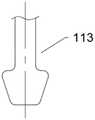
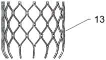
图11为图1中瓣膜支架的结构说明示意图一;FIG. 11 is a schematic diagram 1 of the structure description of the valve stent in FIG. 1;
图12为图1中瓣膜支架的结构说明示意图二;FIG. 12 is a second schematic diagram illustrating the structure of the valve stent in FIG. 1;
图13为图12中心房段的结构说明示意图;Fig. 13 is a schematic diagram illustrating the structure of the central room section of Fig. 12;
图14为图12中心房段和竖直段的俯视图的结构示意图;FIG. 14 is a schematic structural diagram of the top view of the central room section and the vertical section of FIG. 12;
图15为图12中锥形段的俯视图的结构示意图一;FIG. 15 is a schematic structural diagram 1 of the top view of the tapered section in FIG. 12;
图16为另一种实施方式中锥形段俯视图的结构示意图;16 is a schematic structural diagram of a top view of a tapered section in another embodiment;
图17为图7中B部分的放大图;Figure 17 is an enlarged view of part B in Figure 7;
图18为图7中C部分的放大图;Figure 18 is an enlarged view of part C in Figure 7;
图19为图1中内侧支架主视图的结构示意图;FIG. 19 is a schematic structural diagram of the front view of the inner bracket in FIG. 1;
图20为图19的俯视图的结构示意图一;FIG. 20 is a schematic structural diagram 1 of the top view of FIG. 19;
图21为图19的俯视图的结构示意图二;FIG. 21 is a second structural schematic diagram of the top view of FIG. 19;
图22为本发明瓣膜支架设有锁定件的结构示意图;Figure 22 is a schematic structural diagram of the valve stent of the present invention provided with a locking member;
图23为图22右视图的结构示意图一;Fig. 23 is the first structural schematic diagram of the right side view of Fig. 22;
图24为图22右视图的结构示意图二;Fig. 24 is the second structural schematic diagram of the right side view of Fig. 22;
图25为图22右视图的结构示意图三;Figure 25 is a schematic structural diagram three of the right side view of Figure 22;
图26为图22右视图的结构示意图四;Figure 26 is a schematic diagram four of the structure of the right side view of Figure 22;
图27为图2中瓣叶立体图的结构示意图;Figure 27 is a schematic structural diagram of a perspective view of the valve leaflets in Figure 2;
图28为心脏的结构示意图;Figure 28 is a schematic diagram of the structure of the heart;
图29为图28中D部分的放大图;Figure 29 is an enlarged view of part D in Figure 28;
图30为本发明的瓣膜支架置于心脏后的结构示意图;Figure 30 is a schematic structural diagram of the valve stent of the present invention after being placed in the heart;
图31为现有技术的瓣膜支架置于心脏后的结构示意图;Figure 31 is a schematic structural diagram of a valve stent of the prior art after being placed in the heart;
图32为本发明输送装置的结构示意图;Figure 32 is a schematic structural diagram of the conveying device of the present invention;
图33为图32中E部分放大图的结构示意图一;Fig. 33 is the structural schematic diagram 1 of the enlarged view of part E in Fig. 32;
图34为图32中E部分放大图的结构示意图二;Fig. 34 is the second structural schematic diagram of the enlarged view of part E in Fig. 32;
附图标记说明:Description of reference numbers:
1-心脏瓣膜;1 - heart valve;
11-瓣膜支架;111-支架前部;112-支架后部;113-连接爪;1131-第一连接爪;1132-第二连接爪;1141-心房段;1142-竖直段;11421-第一部件;11422-第二部件;1143-锥形段;1144-连接段;1151-心房前部高度;1152-心房后部高度;1153-心房中部高度;1161-瓣环前部高度;1162-瓣环后部高度;1163-瓣环中部高度;1171-椭圆弧形;1172-圆弧形;h11-前部高度;h12-中部高度;h13-后部高度;1181-第一前部;1182-第一后部;1183-圆弧凹槽;11 - valve stent; 111 - stent front; 112 - stent rear; 113 - connecting claw; 1131 - first connecting claw; 1132 - second connecting claw; 1141 - atrium segment; 1142 - vertical segment; 11422-second part; 1143-conical segment; 1144-connecting segment; 1151-atrial anterior height; 1152-atrial posterior height; 1153-atrial mid-height; 1161-annulus anterior height; Annulus posterior height; 1163-annulus middle height; 1171-elliptic arc; 1172-circular arc; h11-anterior height; h12-medial height; h13-posterior height; 1181-first anterior; 1182 - first rear; 1183 - arc groove;
121-第一显影点;122-第二显影点;123-第三显影点;121-first developing point; 122-second developing point; 123-third developing point;
13-内侧支架;13- inner bracket;
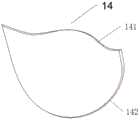
14-瓣叶;141-对合线;142-缝合线;14 - leaflet; 141 - suture; 142 - suture;
15-倒刺;15 - barb;
161-第一瓣裙;162-第二瓣裙;161-first petal skirt; 162-second petal skirt;
17-锁定件;17 - locking piece;
2-输送装置;21-第一收入管;22-第二收入管;221-第一安装部;222-第二安装部;223-第三安装部;224-第四安装部;225-第五安装部;23-第一手轮;24-第二手轮;25-鲁尔接头;26-输送外管;27-外壳;28-连接杆;2-conveying device; 21-first receiving pipe; 22-second receiving pipe; 221-first installation part; 222-second installation part; 223-third installation part; 224-fourth installation part; 225-first installation part Five installation parts; 23-first handwheel; 24-second handwheel; 25-luer joint; 26-transport outer pipe; 27-housing; 28-connecting rod;
3-心脏;31-左心房;32-左心室;33-二尖瓣;331-二尖瓣前叶;332-二尖瓣后叶;34-主动脉瓣。31 - left atrium; 32 - left ventricle; 33 - mitral valve; 331 - anterior leaflet of mitral valve; 332 - posterior leaflet of mitral valve; 34 - aortic valve.
具体实施方式Detailed ways
下面将结合附图对本发明的技术方案进行清楚、完整地描述,显然,所描述的实施例是本发明一部分实施例,而不是全部的实施例。基于本发明中的实施例,本领域普通技术人员在没有做出创造性劳动前提下所获得的所有其他实施例,都属于本发明保护的范围。The technical solutions of the present invention will be clearly and completely described below with reference to the accompanying drawings. Obviously, the described embodiments are part of the embodiments of the present invention, but not all of the embodiments. Based on the embodiments of the present invention, all other embodiments obtained by those of ordinary skill in the art without creative efforts shall fall within the protection scope of the present invention.
在本发明的描述中,需要说明的是,术语“中心”、“上”、“下”、“左”、“右”、“竖直”、“水平”、“内”、“外”等指示的方位或位置关系为基于附图所示的方位或位置关系,仅是为了便于描述本发明和简化描述,而不是指示或暗示所指的装置或元件必须具有特定的方位、以特定的方位构造和操作,因此不能理解为对本发明的限制。此外,术语“第一”、“第二”、“第三”仅用于描述目的,而不能理解为指示或暗示相对重要性。In the description of the present invention, it should be noted that the terms "center", "upper", "lower", "left", "right", "vertical", "horizontal", "inner", "outer", etc. The indicated orientation or positional relationship is based on the orientation or positional relationship shown in the accompanying drawings, which is only for the convenience of describing the present invention and simplifying the description, rather than indicating or implying that the indicated device or element must have a specific orientation or a specific orientation. construction and operation, and therefore should not be construed as limiting the invention. Furthermore, the terms "first", "second", and "third" are used for descriptive purposes only and should not be construed to indicate or imply relative importance.
如图1至图7所示,本发明一实施例提供一种心脏瓣膜1,包括瓣膜支架11和连接爪113,瓣膜支架11的一端与多个连接爪113连接,连接爪113用于与输送心脏瓣膜的输送装置连接,瓣膜支架11和连接爪113收缩至适于装入输送装置时,多个连接爪113在瓣膜支架11的高度方向交错设置;As shown in FIGS. 1 to 7 , an embodiment of the present invention provides a
瓣膜支架11置入心脏3过程中,多个连接爪113按照到瓣膜支架11的距离有序的与输送装置分离。During the process of placing the
具体而言,心脏瓣膜1主要针对心脏原生瓣膜病变后的微创置换,以心脏原生瓣膜中的二尖瓣33为例,二尖瓣33在心脏3中的位置如图28和图29所示,二尖瓣33有2片瓣叶,二尖瓣前叶331位于靠近主动脉瓣34一侧,二尖瓣后叶332位于远离主动脉瓣34的一侧。Specifically, the
瓣膜支架11是心脏瓣膜1的支撑结构,心脏瓣膜1的形状和瓣膜支架11的形状相同。心脏瓣膜1固定于心脏3时,瓣膜支架11与二尖瓣33固定。The
如图7和图18所示,在一实施例中,为了增加瓣膜支架11与二尖瓣33固定的稳定性,在瓣膜支架11上设置倒刺15。倒刺15远离瓣膜支架11的一端呈箭头状。As shown in FIG. 7 and FIG. 18 , in one embodiment, in order to increase the stability of fixing the
倒刺15用于将瓣膜支架11固定在二尖瓣33上,且使得心脏瓣膜1和二尖瓣33的固定强度和可靠性高。The
连接爪113用于与输送心脏瓣膜1的输送装置2连接,多个连接爪113与瓣膜支架11的一端连接,由于瓣膜支架11和连接爪113收缩至适于装入输送装置时,多个连接爪113在瓣膜支架11的高度方向交错设置,瓣膜支架11与输送装置有多个连接位置,且连接位置不在同一平面内,能够增加心脏瓣膜设于输送装置内时力的均匀性,收入过程中力学传递平稳,大大提高心脏瓣膜1的收入性能,且能够增加心脏瓣膜1和输送装置2连接的可靠性;瓣膜支架11置入心脏3过程中,多个连接爪113按照到瓣膜支架11的距离有序的与输送装置分离,多个连接爪113不是同时与输送装置2分离,先与输送装置分离的连接爪113会使瓣膜支架11的部分与二尖瓣33固定好,后面与输送装置分离的连接爪113会使瓣膜支架11剩下的部分有序的与二尖瓣33固定,能够避免瓣膜支架11一次全部释放产生的突然跳动,释放过程中力学传递平稳,从而使心脏瓣膜定位更准确。The connecting
多个连接爪113与输送装置分离的其他顺序,如按照多个连接爪113的圆周排列顺序,只要能够满足连接爪113不是同时与输送装置分离即可。Other sequences in which the plurality of connecting
由于瓣膜支架11和连接爪113收缩至适于装入输送装置时,多个连接爪113在瓣膜支架11的高度方向交错设置,多个连接爪113占用输送装置2的瓣膜支架11高度方向的长度长,相应的占用输送装置2的周向面积小,进而使得输送装置2与瓣膜支架11连接一端的直径小,微创置换需要的创口小,能够减轻手术过程中对人体造成的创伤。When the
瓣膜支架11选用记忆合金、不锈钢、钴铬合金、高分子等材料,以适应瓣膜支架11在置入心脏3过程中、以及工作过程中的形状变化。The
如图3所示,箭头方向为瓣膜支架11的高度方向;如图7中,虚线方向也为瓣膜支架11的高度方向。As shown in FIG. 3 , the arrow direction is the height direction of the
连接爪113的结构根据使用需求确定,如图4所示的连接爪113为竖杆和方形片连接,如图5所示的连接爪113为竖杆和梯形片连接,如图6所示的连接爪113为竖杆和弧形片连接。The structure of the connecting
连接爪113的数量是根据使用需求设置,并不限制于图中所示数量的连接爪113。The number of the
如图1和图4所示,在一实施例中,连接爪113包括第一连接爪1131和第二连接爪1132,多个第一连接爪1131和多个第二连接爪1132在瓣膜支架11的高度方向交错设置,且第一连接爪1131相对第二连接爪1132远离瓣膜支架11;瓣膜支架11置入心脏3过程中,第一连接爪1131先与输送装置2分离,第二连接爪1132再与输送装置2分离。As shown in FIG. 1 and FIG. 4 , in one embodiment, the connecting
在另一实施例中,瓣膜支架11置入心脏3过程中,第二连接爪1132先与输送装置2分离,第一连接爪1131再与输送装置2分离。In another embodiment, when the
在图4所示,由于第一连接爪1131和第二连接爪1132在瓣膜支架11的高度方向交错设置,在保证心脏瓣膜1和输送装置2连接稳定性的前提下,能够减少输送装置2与连接爪113连接需要的直径,进而减少输送装置2伸入人体内部分的直径,微创置换需要的创口小,能够减轻手术过程中对人体造成的创伤。As shown in FIG. 4 , since the
如图4所示,在一实施例中,第一连接爪1131和第二连接爪1132间隔分布,且均布设置,第一连接爪1131和第二连接爪1132与输送装置2连接的均匀性更好,且第一连接爪1131和第二连接爪1132与输送装置2安装过程中和分离过程中力学传递平稳。As shown in FIG. 4 , in one embodiment, the first connecting
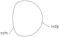
如图7至图10所示,在一实施例中,瓣膜支架11的横向方向包括支架前部111和支架后部112,支架前部111和支架后部112连接,支架前部111位于靠近主动脉瓣34一侧,支架后部112位于远离主动脉瓣34的另一侧;垂直于瓣膜支架11高度方向的截面中,支架前部111为椭圆弧形1171,支架后部112为圆弧形1172,支架前部111与支架后部112相切。As shown in FIG. 7 to FIG. 10 , in one embodiment, the lateral direction of the
瓣膜支架11的横向方向为图7中的箭头方向,与瓣膜支架11的高度方向垂直。The lateral direction of the
心脏瓣膜1置入心脏3后,支架前部111与二尖瓣前叶331对应设置,支架后部112与二尖瓣后叶332对应设置。After the
如图9和图10所示,为椭圆弧形1171和圆弧形1172的连接时原理的结构示意图。椭圆弧形1171的中心与圆弧形1172的圆心之间的距离为t,且0≤t≤30mm。距离t的范围能够使得心脏瓣膜1适应于不同个体二尖瓣33的介入治疗。As shown in FIG. 9 and FIG. 10 , it is a schematic structural diagram of the connection principle of the
二尖瓣33的瓣环在整个心脏3周期内的形状是变化的,垂直于瓣膜支架11高度方向的截面中,支架前部111为椭圆弧形1171,支架后部112为圆弧形1172,支架前部111与支架后部112相切,心脏瓣膜1和瓣膜支架11的外形能够适应整个心脏3周期的瓣环形状,能够尽量降低心脏瓣膜1对人体组织的压迫;且心脏瓣膜1与二尖瓣33的吻合性好,不会与二尖瓣33形成间隙,避免造成瓣周漏,减少并发症的发生概率。The shape of the valve annulus of the
如图1、图2、图19和图20所示,在一实施例中,心脏瓣膜还包括内侧支架13,内侧支架13与瓣膜支架11连接,位于瓣膜支架11的内侧;垂直于瓣膜支架11高度方向的截面中,内侧支架13的截面与瓣膜支架11的截面形状相同。As shown in FIGS. 1 , 2 , 19 and 20 , in one embodiment, the heart valve further includes an
如图1、图2、图19和图21所示,在一实施例中,垂直于瓣膜支架11高度方向的截面中,内侧支架13的截面为圆形。As shown in FIG. 1 , FIG. 2 , FIG. 19 and FIG. 21 , in an embodiment, in a cross section perpendicular to the height direction of the
内侧支架13在瓣膜支架11的高度方向的形状需要与瓣膜支架11的形状适配,内侧支架13在瓣膜支架11的横向方向需要随瓣膜支架11变形,由于瓣环在整个心脏3周期内的形状是变化的,将内侧支架13的截面设置为与瓣膜支架11的截面形状相同,或是内侧支架13的截面为圆形,均能够与瓣环整个心脏3周期内的形状适配。The shape of the
内侧支架13的材料和瓣膜支架11的材料相同,也为记忆合金、不锈钢、钴铬合金、高分子等。The material of the
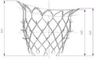
如图7所示,在一实施例中,瓣膜支架11的高度方向,瓣膜支架11靠近主动脉瓣34一端的高度为前部高度h11,远离主动脉瓣34一端的高度为后部高度h13,位于靠近主动脉瓣34一端以及远离主动脉瓣34一端之间中部的高度为中部高度h12;前部高度h11大于后部高度h13,后部高度h13大于中部高度h12。As shown in FIG. 7, in one embodiment, in the height direction of the
如图7和图11中,瓣膜支架11的左侧靠近主动脉瓣34,右侧远离主动脉瓣34,图7中虚线部分的瓣膜支架11高度为中部高度h12。As shown in FIGS. 7 and 11 , the left side of the
如图7所示,瓣膜支架11的上下两端表面均是平滑过渡,瓣膜支架11的形状为马鞍形,由于前部高度h11和后部高度h13均大于中部高度h12,使得瓣膜支架11跟随二尖瓣33变形时,瓣膜支架11上端中部对瓣膜支架11的形状变化阻碍小,使得瓣膜支架11更容易跟随二尖瓣33发生形状变化,提高了心脏瓣膜1随二尖瓣33变形过程中的顺应性,从而降低了对二尖瓣33的压迫,减少病发症。As shown in FIG. 7 , the upper and lower surfaces of the
前部高度h11大于后部高度h13,使得心脏瓣膜1随二尖瓣33变形过程中的顺应性更好。The anterior height h11 is greater than the posterior height h13 , so that the compliance of the
且如图30和图31所示,由于瓣膜支架11在心脏3周期内与二尖瓣33的形状一致性好,这样就减小了心脏瓣膜1对左心房31的体积占位,从而降低肺静脉压力(临床上由于人体左心房31体积较小,血液从肺静脉流入左心房31,如果假体瓣膜占用左心房31的体积大,则会引起肺静脉高压,对人体肺静血管会造成一定的损伤),即左心房31的体积中,s2>s1。And as shown in FIG. 30 and FIG. 31 , since the
在一实施例中,如图11和图12所示,瓣膜支架11的高度方向,瓣膜支架11包括依次连接的心房段1141、竖直段1142、锥形段1143和连接段1144,连接段1144设有连接爪113;In one embodiment, as shown in FIG. 11 and FIG. 12 , in the height direction of the
竖直段1142靠近主动脉瓣34一端的高度为瓣环前部高度1161,远离主动脉瓣34一端的高度为瓣环后部高度1162,位于靠近主动脉瓣34一端以及远离主动脉瓣34一端之间中部的高度为瓣环中部高度1163;The height of the
锥形段1143为台状,锥形段1143的高度为锥形段高度;The
连接爪113到瓣膜支架11的最远距离为连接段高度;The farthest distance from the connecting
瓣环前部高度1161、锥形段高度、连接段高度的高度和为h21,瓣环中部高度1163、锥形段高度、连接段高度的高度和为h22,瓣环后部高度1162、锥形段高度、连接段高度的高度和为h23;h21>h23>h22。The height of the annulus
如图12所示,瓣膜支架11的马鞍形曲线位置位于心房段1141和锥形段1143,也即,心房段1141和锥形段1143均为马鞍形,瓣膜支架11的马鞍形为心房段1141和锥形段1143形成的。As shown in FIG. 12 , the saddle-shaped curve of the
锥形段1143为台状,是指锥形段1143在瓣膜支架11高度方向的两端为平行设置。The tapered
参阅图7和图16所示,在一实施例中,瓣膜支架11的横向方向,锥形段1143包括第一前部1181和第一后部1182,第一前部1181和第一后部1182连接,第一前部1181位于靠近主动脉瓣34一侧,第一后部1182位于远离主动脉瓣34的另一侧;Referring to FIGS. 7 and 16 , in one embodiment, in the lateral direction of the
垂直于瓣膜支架11高度方向的截面中,第一前部1181为椭圆弧形1171,椭圆弧形1171中部设有向椭圆弧形1171中心方向凹陷的圆弧凹槽1183,第一后部1182为圆弧形1172,第一前部1181和第一后部1182相切。In the section perpendicular to the height direction of the
在另一实施例中,瓣膜支架11的横向方向,竖直段1142和锥形段1143均包括第一前部1181和第一后部1182,第一前部1181和第一后部1182连接,第一前部1181位于靠近主动脉瓣34一侧,第一后部1182位于远离主动脉瓣34的另一侧;In another embodiment, in the lateral direction of the
垂直于瓣膜支架11高度方向的截面中,第一前部1181为椭圆弧形1171,椭圆弧形1171中部设有向椭圆弧形1171中心方向凹陷的圆弧凹槽1183,第一后部1182为圆弧形1172,第一前部1181和第一后部1182相切。In the section perpendicular to the height direction of the
在另一实施例中,是竖直段1142包括第一前部1181和第一后部1182。In another embodiment, the
圆弧凹槽1183的设置,用于给左心室32流出到主动脉瓣34提供避让空间,减少阻挡,使得血流更顺畅。The setting of the
如图7和图12所示,在一实施例中,竖直段1142包括围成柱状的竖直部,锥形段1143的外壁和竖直部的外壁之间的夹角al为:0°<al<90°;和/或,As shown in FIG. 7 and FIG. 12 , in one embodiment, the
如图7和图13所示,在一实施例中,心房段1141的外壁和竖直部的外壁之间的夹角a3为:0°<a3<180°。As shown in FIG. 7 and FIG. 13 , in one embodiment, the included angle a3 between the outer wall of the
如图7和图17所示,竖直段1142包括第一部件11421和第二部件11422,一个第一部件11421和两个第二部件11422连接,其中第一部件11421与瓣膜支架11的高度方向平行。As shown in FIGS. 7 and 17 , the
如图1和图2所示,在一实施例中,心脏瓣膜还包括连接件,心房段1141与竖直段1142为分体结构,心房段1141和竖直段1142通过连接件连接。As shown in FIGS. 1 and 2 , in one embodiment, the heart valve further includes a connector, the
心房段1141与竖直段1142为分体结构,相对于心房段1141与竖直段1142一体成型,心房段1141与竖直段1142之间更加柔软,增加随二尖瓣33变形过程中的顺应性。The
如图27所示,在一实施例中,还包括瓣叶14,瓣叶14的外周包括对合线141和缝合线142,缝合线142与瓣膜支架11或内侧支架13连接,对合线141与其他瓣叶14的对合线141相接触,对合线141呈W型。As shown in FIG. 27 , in one embodiment, the
瓣叶14的设计采用W形,降低了瓣叶14与内侧支架13连接时顶部的应力集中。又使得瓣叶14与瓣叶14对合部位的可靠性。The design of the
瓣叶14的材料为猪心包或牛心包等。The material of the
如图22至图26所示,在一实施例中,瓣膜支架11还包括锁定件17,锁定件17与瓣膜支架11的外壁连接,锁定件17为长条状,锁定件17用于与心脏的瓣叶14连接,锁定件的数量不做限制。As shown in FIG. 22 to FIG. 26 , in one embodiment, the
如图23所示,在一实施例中,瓣膜支架11包括网格结构,锁定件17的两端与同一网格结构的一角连接。As shown in FIG. 23 , in one embodiment, the
如图24所示,在一实施例中,锁定件17与连接段1144连接。锁定件17的两端分别与瓣膜支架11相邻两个网格的一角连接。As shown in FIG. 24 , in one embodiment, the locking
如图25所示,在一实施例中,锁定件17的两端分别与瓣膜支架11同一网格的两个角连接。As shown in FIG. 25 , in an embodiment, two ends of the locking
如图26所示,在一实施例中,锁定件17的两端分别与间隔设置的两个网格结构的角连接,该间隔设置的两个网格结构之间的网格结构一角连接有连接爪113。As shown in FIG. 26 , in one embodiment, both ends of the locking
在一实施例中,如图30中,瓣膜支架11和主动脉瓣34之间的夹角为a-2,如图31中,瓣膜支架11和主动脉瓣34之间的夹角为a-1,由于a-2>a-1,心脏瓣膜1对左心室32流出道主动脉瓣34的阻挡变小,使得血流更顺畅。In one embodiment, as shown in FIG. 30 , the angle between the
如图2所示,在一实施例中,心脏瓣膜1还包括三个显影点,显影点位于椭圆弧形1171的两端,以及支架后部112的中心。As shown in FIG. 2 , in one embodiment, the
如图2所示,三个显影点分别为第一显影点121、第二显影点122和第三显影点123,所示第一显影点121和第二显影点122分别位于弧形部的两端,所示第三显影点123位于圆弧形1172的中部处。显影点用于指示心脏瓣膜1在人体内的位置,使得心脏瓣膜1可以准缺的置入心脏3内。As shown in FIG. 2 , the three developing points are the first developing
显影点的材料为泊金、银、钽等,能够用于显影的材料。The material of the development point is poin, silver, tantalum, etc., which can be used for development.
在一实施例中,显影点具有两个、四个、五个,显影点的数量按照需求设置。In one embodiment, there are two, four, or five developing points, and the number of developing points is set according to requirements.
如图1所示,在一实施例中,所示心脏瓣膜1包括第一瓣裙161和第二瓣裙162,第一瓣裙161与瓣膜支架11连接,第二瓣裙162与内侧支架13连接。As shown in FIG. 1 , in one embodiment, the
第一瓣裙161和第二瓣裙162的材料为布或牛心包、猪心包等。The material of the
第一瓣裙161能够作为连接件,心房段1141与竖直段1142通过第一瓣裙161连接。The
在一实施例中,瓣膜支架11、内侧支架13、第一瓣裙161、第二瓣裙162、瓣叶14和显影点的连接方式为,瓣膜支架11与内侧支架13通过焊接、粘接等方式连接,瓣膜支架11与第一瓣裙161通过缝线缝合在一起,内侧支架13与第二瓣裙162通过缝线缝合在一起,内侧支架13与瓣叶14通过缝线缝合在一起,第一显影点121、第二显影点122和第三显影点123均与瓣膜支架11通过焊接、粘接等方式连接。上述所指缝线的材料为PE,高分子聚脂,PTFE,PP,PA等。In one embodiment, the
在一实施例中,心脏瓣膜1不包括内侧支架13,瓣叶14直接与瓣膜支架11连接,且第一瓣裙161和瓣叶14缝制于瓣膜支架11上。In one embodiment, the
如图32至图34所示,本发明一实施例还提供一种瓣膜输送装置2,包括收入管、连接杆28和操作机构,收入管和/或连接杆28与操作机构连接,连接杆28与上项的心脏瓣膜连接,收入管内用于安装心脏瓣膜和连接杆28;As shown in FIG. 32 to FIG. 34 , an embodiment of the present invention further provides a
连接杆28上设有多个安装部,安装部用于一一对应安装连接爪113,安装部在瓣膜支架11的高度方向交错设置;The connecting
瓣膜支架11置入心脏3过程中,多个安装部按照到瓣膜支架11的距离有序的与连接爪113分离。During the process of placing the
由于连接爪113与安装部有多个连接位置,且连接位置不在同一平面内,能够增加心脏瓣膜设于输送装置内时力的均匀性,收入过程中力学传递平稳,大大提高心脏瓣膜1的收入性能,且能够增加心脏瓣膜1和输送装置2连接的可靠性;瓣膜支架11置入心脏3过程中,多个安装部按照设定顺序有序的与连接爪113分离,多个安装部不是同时与连接爪113分离,先与安装部分离的连接爪113会使瓣膜支架11的部分与二尖瓣33固定好,后面与安装部分离的连接爪113会使瓣膜支架11剩下的部分有序的与二尖瓣33固定,能够避免瓣膜支架11一次全部释放产生的突然跳动,释放过程中力学传递平稳,从而使心脏瓣膜定位更准确。Since the
且由于安装部在瓣膜支架11的高度方向交错设置,多个安装部占用连接杆28高度方向的长度长,相应的占用连接杆28的周向面积小,进而使得连接杆28的直径小,微创置换需要的创口小,能够减轻手术过程中对人体造成的创伤。And because the mounting parts are staggered in the height direction of the
如图32所示,收入管包括第一收入管21和第二收入管22。As shown in FIG. 32 , the income pipe includes a
如图33所示,安装部包括第一安装部221和第二安装部222,第一安装部221远离输送装置的操作机构。As shown in FIG. 33 , the installation part includes a
如图34所示,安装部包括第三安装部223、第四安装部224和第五安装部225,第五安装部225远离输送装置的操作机构。As shown in FIG. 34 , the mounting portion includes a third mounting
如图32所示一实施例中,操作机构包括第一手轮23、第二手轮24、鲁尔接头25、输送外管26和外壳27,第一手轮23、第二手轮24、鲁尔接头25、输送外管26均与外壳27连接,第一收入管21和第二收入管22进入外壳27内,并从输送外管26伸出,第一手轮23和第二手轮24分别用于操作第一收入管21和第二收入管22,实现第一收入管21和第二收入管22的动作。In an embodiment shown in Figure 32, the operating mechanism includes a
第一收入管21和/或第二收入管22上也设置显影点,用于在心脏瓣膜1释放之前圆周方向定位心脏瓣膜1,显影点数量与心脏瓣膜1上显影点相同,且圆周方向位置与心脏瓣膜1上显影点位置相对应。The
显然,上述实施例仅仅是为清楚地说明所作的举例,而并非对实施方式的限定。对于所属领域的普通技术人员来说,在上述说明的基础上还可以做出其它不同形式的变化或变动。这里无需也无法对所有的实施方式予以穷举。而由此所引伸出的显而易见的变化或变动仍处于本发明创造的保护范围之中。Obviously, the above-mentioned embodiments are only examples for clear description, and are not intended to limit the implementation manner. For those of ordinary skill in the art, changes or modifications in other different forms can also be made on the basis of the above description. There is no need and cannot be exhaustive of all implementations here. And the obvious changes or changes derived from this are still within the protection scope of the present invention.
Claims (10)
Translated fromChinesePriority Applications (1)
| Application Number | Priority Date | Filing Date | Title |
|---|---|---|---|
| CN202010967331.8ACN112022441A (en) | 2020-09-15 | 2020-09-15 | Heart valve and valve conveying device |
Applications Claiming Priority (1)
| Application Number | Priority Date | Filing Date | Title |
|---|---|---|---|
| CN202010967331.8ACN112022441A (en) | 2020-09-15 | 2020-09-15 | Heart valve and valve conveying device |
Publications (1)
| Publication Number | Publication Date |
|---|---|
| CN112022441Atrue CN112022441A (en) | 2020-12-04 |
Family
ID=73590162
Family Applications (1)
| Application Number | Title | Priority Date | Filing Date |
|---|---|---|---|
| CN202010967331.8APendingCN112022441A (en) | 2020-09-15 | 2020-09-15 | Heart valve and valve conveying device |
Country Status (1)
| Country | Link |
|---|---|
| CN (1) | CN112022441A (en) |
Cited By (8)
| Publication number | Priority date | Publication date | Assignee | Title |
|---|---|---|---|---|
| CN113558823A (en)* | 2021-07-23 | 2021-10-29 | 上海欣吉特生物科技有限公司 | Valve support of intervention treatment reaches valve replacement device including it |
| CN113558822A (en)* | 2021-07-23 | 2021-10-29 | 上海欣吉特生物科技有限公司 | An interventional mitral valve replacement system |
| CN113855333A (en)* | 2021-10-18 | 2021-12-31 | 上海欣吉特生物科技有限公司 | A split valve stent and an interventional mitral valve replacement system including the same |
| CN113855324A (en)* | 2021-09-18 | 2021-12-31 | 上海欣吉特生物科技有限公司 | Valve support reaches intervention mitral valve replacement system including it |
| CN114191155A (en)* | 2021-12-06 | 2022-03-18 | 杭州唯强医疗科技有限公司 | Conveying device and conveying system for conveying stents |
| WO2023133723A1 (en)* | 2022-01-12 | 2023-07-20 | 金仕生物科技(常熟)有限公司 | Interventional mitral valve stent having two side claws, and interventional mitral valve |
| CN117503443A (en)* | 2023-12-15 | 2024-02-06 | 归创通桥医疗科技股份有限公司 | Point stent system, point stent and point stent delivery system |
| CN119184912A (en)* | 2023-06-26 | 2024-12-27 | 江苏臻亿医疗科技有限公司 | Stent for valve prosthesis and valve prosthesis |
Citations (17)
| Publication number | Priority date | Publication date | Assignee | Title |
|---|---|---|---|---|
| CN2135346Y (en)* | 1992-09-12 | 1993-06-09 | 中国人民解放军第四军医大学第一附属医院 | Plasticity bicuspid valve shaping ring |
| US20130304200A1 (en)* | 2011-10-19 | 2013-11-14 | Foundry Newco Xii, Inc. | Prosthetic heart valve devices, prosthetic mitral valves and associated systems and methods |
| CN203970617U (en)* | 2014-07-14 | 2014-12-03 | 北京思达医用装置有限公司 | A kind of property implanted Cardiac valve prosthesis forming ring |
| CN104302247A (en)* | 2011-11-23 | 2015-01-21 | 内奥瓦斯克迪亚拉公司 | sequentially deployed transcatheter mitral valve prosthesis |
| CN105520792A (en)* | 2016-02-02 | 2016-04-27 | 上海纽脉医疗科技有限公司 | D-shaped invasive prosthetic heart valve |
| CN205307151U (en)* | 2016-01-07 | 2016-06-15 | 上海市同济医院 | A atrioventricular valve valve support for $puncturing put into and conveying system thereof |
| CN105726167A (en)* | 2016-02-02 | 2016-07-06 | 上海纽脉医疗科技有限公司 | Involved artificial heart valve prosthesis |
| CN106420114A (en)* | 2016-10-24 | 2017-02-22 | 宁波健世生物科技有限公司 | Heart valve prosthesis |
| CN107212950A (en)* | 2017-07-12 | 2017-09-29 | 宁波健世生物科技有限公司 | A kind of heart valve prosthesis with clamping device |
| CN108260342A (en)* | 2015-09-18 | 2018-07-06 | 微仙美国有限公司 | Releasable delivery system |
| US20180271651A1 (en)* | 2015-12-03 | 2018-09-27 | Tendyne Holdings, Inc. | Frame features for prosthetic mitral valves |
| CN109106470A (en)* | 2018-09-21 | 2019-01-01 | 上海纽脉医疗科技有限公司 | heart valve stent |
| CN109199640A (en)* | 2018-10-24 | 2019-01-15 | 宁波健世生物科技有限公司 | A kind of artificial valve prosthese |
| CN110151368A (en)* | 2019-06-28 | 2019-08-23 | 微创神通医疗科技(上海)有限公司 | Vascular Implants, Delivery Devices, and Medical Devices |
| CN209316148U (en)* | 2018-12-08 | 2019-08-30 | 北京市普惠生物医学工程有限公司 | Heart valve forming ring |
| CN111035473A (en)* | 2018-10-15 | 2020-04-21 | 上海微创心通医疗科技有限公司 | Artificial heart valve prosthesis and stent thereof |
| CN213665978U (en)* | 2020-09-15 | 2021-07-13 | 王洪志 | Heart valve and valve conveying device |
- 2020
- 2020-09-15CNCN202010967331.8Apatent/CN112022441A/enactivePending
Patent Citations (17)
| Publication number | Priority date | Publication date | Assignee | Title |
|---|---|---|---|---|
| CN2135346Y (en)* | 1992-09-12 | 1993-06-09 | 中国人民解放军第四军医大学第一附属医院 | Plasticity bicuspid valve shaping ring |
| US20130304200A1 (en)* | 2011-10-19 | 2013-11-14 | Foundry Newco Xii, Inc. | Prosthetic heart valve devices, prosthetic mitral valves and associated systems and methods |
| CN104302247A (en)* | 2011-11-23 | 2015-01-21 | 内奥瓦斯克迪亚拉公司 | sequentially deployed transcatheter mitral valve prosthesis |
| CN203970617U (en)* | 2014-07-14 | 2014-12-03 | 北京思达医用装置有限公司 | A kind of property implanted Cardiac valve prosthesis forming ring |
| CN108260342A (en)* | 2015-09-18 | 2018-07-06 | 微仙美国有限公司 | Releasable delivery system |
| US20180271651A1 (en)* | 2015-12-03 | 2018-09-27 | Tendyne Holdings, Inc. | Frame features for prosthetic mitral valves |
| CN205307151U (en)* | 2016-01-07 | 2016-06-15 | 上海市同济医院 | A atrioventricular valve valve support for $puncturing put into and conveying system thereof |
| CN105520792A (en)* | 2016-02-02 | 2016-04-27 | 上海纽脉医疗科技有限公司 | D-shaped invasive prosthetic heart valve |
| CN105726167A (en)* | 2016-02-02 | 2016-07-06 | 上海纽脉医疗科技有限公司 | Involved artificial heart valve prosthesis |
| CN106420114A (en)* | 2016-10-24 | 2017-02-22 | 宁波健世生物科技有限公司 | Heart valve prosthesis |
| CN107212950A (en)* | 2017-07-12 | 2017-09-29 | 宁波健世生物科技有限公司 | A kind of heart valve prosthesis with clamping device |
| CN109106470A (en)* | 2018-09-21 | 2019-01-01 | 上海纽脉医疗科技有限公司 | heart valve stent |
| CN111035473A (en)* | 2018-10-15 | 2020-04-21 | 上海微创心通医疗科技有限公司 | Artificial heart valve prosthesis and stent thereof |
| CN109199640A (en)* | 2018-10-24 | 2019-01-15 | 宁波健世生物科技有限公司 | A kind of artificial valve prosthese |
| CN209316148U (en)* | 2018-12-08 | 2019-08-30 | 北京市普惠生物医学工程有限公司 | Heart valve forming ring |
| CN110151368A (en)* | 2019-06-28 | 2019-08-23 | 微创神通医疗科技(上海)有限公司 | Vascular Implants, Delivery Devices, and Medical Devices |
| CN213665978U (en)* | 2020-09-15 | 2021-07-13 | 王洪志 | Heart valve and valve conveying device |
Non-Patent Citations (1)
| Title |
|---|
| 黄利荣;蒋红亮;刘国锋;王春生;: "自制软质人工二尖瓣成形环在二尖瓣修复术中的应用", 山东医药, no. 27, 25 September 2007 (2007-09-25)* |
Cited By (11)
| Publication number | Priority date | Publication date | Assignee | Title |
|---|---|---|---|---|
| CN113558823A (en)* | 2021-07-23 | 2021-10-29 | 上海欣吉特生物科技有限公司 | Valve support of intervention treatment reaches valve replacement device including it |
| CN113558822A (en)* | 2021-07-23 | 2021-10-29 | 上海欣吉特生物科技有限公司 | An interventional mitral valve replacement system |
| CN113558822B (en)* | 2021-07-23 | 2024-11-05 | 上海欣吉特生物科技有限公司 | An interventional mitral valve replacement system |
| CN113855324A (en)* | 2021-09-18 | 2021-12-31 | 上海欣吉特生物科技有限公司 | Valve support reaches intervention mitral valve replacement system including it |
| CN113855333A (en)* | 2021-10-18 | 2021-12-31 | 上海欣吉特生物科技有限公司 | A split valve stent and an interventional mitral valve replacement system including the same |
| CN113855333B (en)* | 2021-10-18 | 2024-12-17 | 上海欣吉特生物科技有限公司 | Split valve support and intervention mitral valve replacement system comprising same |
| CN114191155A (en)* | 2021-12-06 | 2022-03-18 | 杭州唯强医疗科技有限公司 | Conveying device and conveying system for conveying stents |
| WO2023133723A1 (en)* | 2022-01-12 | 2023-07-20 | 金仕生物科技(常熟)有限公司 | Interventional mitral valve stent having two side claws, and interventional mitral valve |
| CN119184912A (en)* | 2023-06-26 | 2024-12-27 | 江苏臻亿医疗科技有限公司 | Stent for valve prosthesis and valve prosthesis |
| WO2025001474A1 (en)* | 2023-06-26 | 2025-01-02 | 江苏臻亿医疗科技有限公司 | Stent for valve prosthesis, and valve prosthesis |
| CN117503443A (en)* | 2023-12-15 | 2024-02-06 | 归创通桥医疗科技股份有限公司 | Point stent system, point stent and point stent delivery system |
Similar Documents
| Publication | Publication Date | Title |
|---|---|---|
| CN112022441A (en) | Heart valve and valve conveying device | |
| CN108578016B (en) | Trans-apex implantable mitral valve device | |
| EP3520735B1 (en) | Heart valve prosthesis fixed through interventricular septum | |
| CN109199641B (en) | Artificial valve prosthesis with fixing piece | |
| CN109199640B (en) | Artificial valve prosthesis | |
| CN109414321A (en) | The device for treating valvular regurgitation | |
| CN213665978U (en) | Heart valve and valve conveying device | |
| CN102985032A (en) | mitral valve prosthesis | |
| WO2019033989A1 (en) | Heart valve prosthesis | |
| JP2022533369A (en) | Stent device for prosthetic heart valve | |
| CN113855326B (en) | Artificial heart valve | |
| CN113693784A (en) | Heart valve support | |
| CN117100459B (en) | Valve stent and valve prosthesis | |
| WO2023284663A1 (en) | Valve stent, valve prosthesis and valve prosthesis system | |
| CN113476181A (en) | Mitral valve repair support | |
| CN115105264A (en) | Valve stent and valve prosthesis system | |
| CN116269942A (en) | Artificial heart valve | |
| CN217430265U (en) | Valve prosthesis | |
| CN114681139A (en) | Valve stent and prosthetic valve assembly | |
| CN213156729U (en) | Novel valve prosthesis with adjustable fixing end | |
| CN215688788U (en) | Valve prosthesis and valve prosthesis system | |
| CN222708461U (en) | A cardiac implant prosthesis | |
| CN114831778A (en) | Support for repairing mitral valve | |
| CN114831778B (en) | A stent for mitral valve repair | |
| CN219782851U (en) | Reverse flow support with folded inflow end |
Legal Events
| Date | Code | Title | Description |
|---|---|---|---|
| PB01 | Publication | ||
| PB01 | Publication | ||
| SE01 | Entry into force of request for substantive examination | ||
| SE01 | Entry into force of request for substantive examination | ||
| CB02 | Change of applicant information | ||
| CB02 | Change of applicant information | Address after:3 xidawang Road, Chaoyang District, Beijing 100022 Applicant after:Wang Hongzhi Address before:065201 Room 401, unit 2, building 23, Fucheng phase IV, Yanjiao Development Zone, Langfang City, Hebei Province Applicant before:Wang Hongzhi |