CN112022313A - A three-dimensional distraction reduction device for calcaneal fractures - Google Patents
A three-dimensional distraction reduction device for calcaneal fracturesDownload PDFInfo
- Publication number
- CN112022313A CN112022313ACN202010983268.7ACN202010983268ACN112022313ACN 112022313 ACN112022313 ACN 112022313ACN 202010983268 ACN202010983268 ACN 202010983268ACN 112022313 ACN112022313 ACN 112022313A
- Authority
- CN
- China
- Prior art keywords
- traction
- rod
- ring
- distraction
- sliding
- Prior art date
- Legal status (The legal status is an assumption and is not a legal conclusion. Google has not performed a legal analysis and makes no representation as to the accuracy of the status listed.)
- Granted
Links
- 230000009467reductionEffects0.000titleclaimsabstractdescription76
- 206010016970Foot fractureDiseases0.000claimsdescription13
- 230000000670limiting effectEffects0.000claimsdescription9
- 210000002082fibulaAnatomy0.000abstractdescription9
- 210000002303tibiaAnatomy0.000abstractdescription9
- 206010017076FractureDiseases0.000description41
- 238000010586diagramMethods0.000description20
- 210000000459calcaneusAnatomy0.000description9
- 230000002093peripheral effectEffects0.000description6
- 230000000694effectsEffects0.000description5
- 238000004519manufacturing processMethods0.000description5
- 238000000034methodMethods0.000description5
- 210000002683footAnatomy0.000description4
- 230000008569processEffects0.000description4
- 208000027418Wounds and injuryDiseases0.000description3
- 230000006378damageEffects0.000description3
- 208000014674injuryDiseases0.000description3
- 210000004872soft tissueAnatomy0.000description3
- 210000000457tarsusAnatomy0.000description3
- 241000469816VarusSpecies0.000description2
- 238000002224dissectionMethods0.000description2
- 238000003825pressingMethods0.000description2
- 241001227561ValgusSpecies0.000description1
- 238000005452bendingMethods0.000description1
- 210000000988bone and boneAnatomy0.000description1
- 230000008859changeEffects0.000description1
- 230000004064dysfunctionEffects0.000description1
- 210000003414extremityAnatomy0.000description1
- 239000000463materialSubstances0.000description1
- 239000012567medical materialSubstances0.000description1
- 230000000149penetrating effectEffects0.000description1
- 238000001356surgical procedureMethods0.000description1
- 210000001137tarsal boneAnatomy0.000description1
Images


Classifications
- A—HUMAN NECESSITIES
- A61—MEDICAL OR VETERINARY SCIENCE; HYGIENE
- A61B—DIAGNOSIS; SURGERY; IDENTIFICATION
- A61B17/00—Surgical instruments, devices or methods
- A61B17/56—Surgical instruments or methods for treatment of bones or joints; Devices specially adapted therefor
- A61B17/58—Surgical instruments or methods for treatment of bones or joints; Devices specially adapted therefor for osteosynthesis, e.g. bone plates, screws or setting implements
- A61B17/60—Surgical instruments or methods for treatment of bones or joints; Devices specially adapted therefor for osteosynthesis, e.g. bone plates, screws or setting implements for external osteosynthesis, e.g. distractors, contractors
- A61B17/62—Ring frames, i.e. devices extending around the bones to be positioned
Landscapes
- Health & Medical Sciences (AREA)
- Orthopedic Medicine & Surgery (AREA)
- Life Sciences & Earth Sciences (AREA)
- Surgery (AREA)
- Biomedical Technology (AREA)
- Engineering & Computer Science (AREA)
- Nuclear Medicine, Radiotherapy & Molecular Imaging (AREA)
- Heart & Thoracic Surgery (AREA)
- Medical Informatics (AREA)
- Molecular Biology (AREA)
- Animal Behavior & Ethology (AREA)
- General Health & Medical Sciences (AREA)
- Public Health (AREA)
- Veterinary Medicine (AREA)
- Surgical Instruments (AREA)
Abstract
Translated fromChinese
Description
Translated fromChinese技术领域technical field
本发明属于医疗器械技术领域,具体涉及一种跟骨骨折三维牵引复位装置。The invention belongs to the technical field of medical devices, and in particular relates to a three-dimensional distraction reduction device for calcaneal fractures.
背景技术Background technique
跟骨骨折是足跗骨中最常见的骨折,治疗不当可引起较为严重的患肢功能障碍。现有技术中对于跟骨骨折的患者,如果要做跟骨复位,一般都需要通过手术进行治疗。具体来说,一般需要在胫腓骨、跟骨和趾骨等位置打上牵引针,然后利用牵引弓对牵引针进行牵引从而对跟骨的长度、高度、内外翻角度等进行恢复。Calcaneal fractures are the most common fractures in the tarsal bones, and improper treatment can lead to more serious limb dysfunction. For patients with calcaneal fractures in the prior art, if calcaneal reduction is to be performed, surgery is generally required. Specifically, it is generally necessary to place traction pins on the tibia and fibula, calcaneus, and phalanges, and then use the traction arch to distract the traction pins to restore the length, height, and valgus angle of the calcaneus.
现有的治疗过程中,一般直接采用牵引弓和牵引针的配合进行牵引,牵引过程中需要医生单纯靠手进行牵引,因此对于牵引角度和力量的控制不好把握,因此跟骨骨折牵引对于医生的临床经验、牵引力度和牵引角度的控制等都具有较高的要求。In the existing treatment process, the traction arch and the traction needle are generally used directly for traction. During the traction process, the doctor needs to use the hand to perform traction, so the control of the traction angle and force is not easy to grasp. Therefore, the traction for calcaneal fractures is very important for doctors. Clinical experience, traction force and traction angle control all have high requirements.
为了降低降低跟骨骨折牵引的难度,协助医生更好的实现对跟骨的长度、高度以及特定角度角的矫正,以及对内外翻角度的纠正。有必要研发一种跟骨骨折三维牵引复位装置。In order to reduce the difficulty of reducing the distraction of calcaneal fractures, assist the doctor to better achieve the correction of the length, height and specific angle of the calcaneus, as well as the correction of the varus and varus angle. It is necessary to develop a three-dimensional distraction reduction device for calcaneal fractures.
发明内容SUMMARY OF THE INVENTION
为了解决临床上采用牵引针和牵引弓对跟骨骨折进行牵引过程中,牵引角度和力量的控制不好把握的技术问题,本发明提供一种跟骨骨折三维牵引复位装置。In order to solve the technical problem that the control of the traction angle and the force is not well controlled during the clinical traction of the calcaneus fracture by using the traction needle and the traction bow, the present invention provides a three-dimensional traction reduction device for the calcaneus fracture.
一种跟骨骨折三维牵引复位装置,包括复位双环、牵引弓和牵拉杆;其中所述复位双环包括相对间隔设置的两个环结构,两个所述环结构之间通过多个支撑杆相连接,在所述复位双环上设置有固定件,所述固定件对胫腓骨牵引针的两端进形固定;其中所述牵引弓包括牵引针固定端和牵拉端;其中所述牵拉杆设置于所述复位双环上,牵拉杆第一端伸入到两个双环结构之间,所述牵拉杆第一端与所述牵拉端可拆卸连接,所述牵拉杆在所述复位双环上的连接位置和伸入到两个环结构之间的长度均可调节。A three-dimensional distraction reduction device for calcaneal fracture, comprising a reduction double ring, a distraction arch and a traction rod; wherein the reduction double ring comprises two ring structures arranged at opposite intervals, and the two ring structures are connected to each other by a plurality of support rods. connection, a fixing member is provided on the reset double ring, and the fixing member is fixed to the two ends of the tibia and fibula traction needle; wherein the traction arch comprises a traction needle fixed end and a traction end; wherein the traction rod It is arranged on the reset double ring, the first end of the pulling rod extends between the two double ring structures, the first end of the pulling rod is detachably connected with the pulling end, and the pulling rod is in the The connection position on the reset double ring and the length extending between the two ring structures can be adjusted.
本发明中的跟骨骨折三维牵引复位装置,在使用时患者脚部伸入到两个环结构之间,其中的固定件对固定于患者胫腓骨处的牵引针的两端进行固定,牵引弓对患者脚部的其他部分的牵引针进行固定;通过调节其中牵拉杆在复位双环上的位置带动在环结构上牵引弓靠近或者远离固定件,从而达到恢复跟骨角度的作用;通过调节牵拉杆伸入到两个环结构之间的长度带动牵引弓向靠近或者远离环结构中心位置,从而达到恢复跟骨的长度的作用;其中支撑件的设置使得复位装置整体结构稳定可靠;其中牵拉杆第一端与牵拉端可拆卸连接使得操作和使用更加方便;本发明中的复位装置可以对跟骨骨折进行三维的牵引复位,通过对其中的牵拉杆的调节可以精准控制牵引角度和力度,降低操作难度,节约人力;本设计适用于任何类型的跟骨骨折。The three-dimensional distraction reduction device for calcaneal fractures in the present invention extends the patient's foot between the two ring structures during use, and the fixing member fixes both ends of the distraction pin fixed to the patient's tibia and fibula, and the distraction arch Fix the traction needle on other parts of the patient's foot; adjust the position of the traction rod on the double-reduction ring to drive the traction arch on the ring structure to approach or move away from the fixture, so as to restore the calcaneal angle; by adjusting the traction The length of the pull rod extending between the two ring structures drives the traction arch to approach or move away from the center of the ring structure, so as to achieve the effect of restoring the length of the calcaneus; the arrangement of the support makes the overall structure of the reduction device stable and reliable; The detachable connection between the first end of the pulling rod and the pulling end makes the operation and use more convenient; the reduction device in the present invention can perform three-dimensional traction reduction for calcaneal fractures, and the traction angle can be precisely controlled by adjusting the pulling rod. and strength, reduce the difficulty of operation and save manpower; this design is suitable for any type of calcaneal fracture.
进一步的,其中所述牵引弓和牵拉杆分别有两个,两个牵拉杆在所述复位双环上的位置与所述固定件在所述复位双环上的位置之间的连线呈三角形。此种设置中,设置有两个牵引弓,两者分别对跗骨和跟骨结节处的牵引针进行固定,在使用时可以对跟骨长度和角度的调节更加方便,使得该复位装置对于形变严重,高能量损伤的复杂跟骨骨折的复位有很大优势。具体来说平方便复位,易于维持位置,减少软组织剥离。Further, there are two traction bows and two traction rods respectively, and the connecting line between the positions of the two traction rods on the reset double ring and the position of the fixing member on the reset double ring is a triangle. . In this setting, there are two traction arches, which respectively fix the traction pins at the tarsus and calcaneal tubercle, and can adjust the length and angle of the calcaneus more conveniently during use, so that the reduction device is suitable for The reduction of complex calcaneal fractures with severe deformation and high-energy injury has great advantages. Specifically, the level is convenient for reduction, easy to maintain the position, and reduces soft tissue dissection.
进一步的,所述环结构整体为圆环,在两个所述环结构之间还设置有两个滑动杆,所述滑动杆可以沿所述环结构滑动并定位;每个所述牵拉杆连接到一个所述滑动杆上并朝向所述环结构的中心处设置。此种设置中,通过设置滑动杆实现牵拉杆在环结构上的位置的调节,结构简单便于实现。Further, the ring structure is a circular ring as a whole, and two sliding rods are further arranged between the two ring structures, and the sliding rods can slide and locate along the ring structures; each of the pulling rods Connected to one of the sliding rods and positioned towards the center of the ring structure. In this arrangement, the adjustment of the position of the pulling rod on the ring structure is realized by arranging the sliding rod, and the structure is simple and convenient to realize.
进一步的,两个所述环结构通过三个所述支撑杆连接,三个支撑杆在所述环结构上均匀设置;所述固定件、两个滑动杆分别设置于两个不同的支撑杆之间。此种设置中,其中三个支撑杆均匀是设置使得复位双环结构稳定性好;并且其中固定件和两个滑动杆分开设置,从而使得牵引复位时复位双环上相邻两个支撑杆之间分别受力,使得牵拉复位过程中复位双环受力均匀,进一步增强了复位双环的稳定性。Further, the two ring structures are connected by three support rods, and the three support rods are evenly arranged on the ring structure; the fixing member and the two sliding rods are respectively arranged between the two different support rods. between. In this arrangement, the three support rods are evenly arranged to make the structure of the reset double ring have good stability; and the fixing member and the two sliding rods are arranged separately, so that the two adjacent support rods on the reset double ring are respectively set during the traction reset. The force is applied, so that the force of the reduction double ring is uniform during the process of pulling and reduction, which further enhances the stability of the reduction double ring.
进一步的,在所述滑动杆上设置有牵拉杆底座,所述牵拉杆底座上设置有内螺纹,所述牵拉杆外壁上设置有与所述内螺纹配合的外螺纹,通过旋转所述牵拉杆实现所述牵拉杆伸入两个环结构之间的长度。此种设置中,通过牵拉底座上的内螺纹与牵拉杆外周壁上的外螺纹的螺纹配合,实现了牵拉杆在滑动杆上的固定,并且只要通过旋转牵拉杆就可以实现对牵拉杆伸入到两个环结构之间的长度进行调节,结构简单便于生产和操作。Further, a pulling rod base is arranged on the sliding rod, an inner thread is arranged on the pulling rod base, and an outer thread that cooperates with the inner thread is arranged on the outer wall of the pulling rod. The pulling rod realizes the length that the pulling rod extends between the two ring structures. In this arrangement, the fixing of the pulling rod on the sliding rod is realized by the thread matching of the inner thread on the pulling base and the outer thread on the outer peripheral wall of the pulling rod, and the adjustment of the pulling rod can be realized only by rotating the pulling rod. The length of the pulling rod extending between the two ring structures can be adjusted, and the structure is simple and convenient for production and operation.
进一步的,在每个滑动杆的两端均设置有一个滑动凸起,在两个环结构上相对的位置上设置有两对用于容纳所述滑动凸起的滑动凹槽,所述滑动凹槽相对的面上为允许所述滑动杆滑动的槽口。此种设置中,其中滑动凸起与滑动凹槽的设置可以实现滑动杆在复位双环上的位置的调节,结构简单,便于生产和操作。Further, a sliding protrusion is provided at both ends of each sliding rod, and two pairs of sliding grooves for accommodating the sliding protrusions are provided at opposite positions on the two ring structures. On the opposite side of the slot are notches that allow the sliding rod to slide. In this arrangement, the arrangement of the sliding protrusion and the sliding groove can realize the adjustment of the position of the sliding rod on the reset double ring, the structure is simple, and the production and operation are convenient.
进一步的,每个滑动杆的至少一个滑动凸起上设置有限位销,所述环结构上设置有多个与所述限位销对应的限位孔,所述限位孔在所述环结构上沿滑动凹槽延伸的方向均匀设置;自然状态所述限位销伸入所述限位孔中实现所述滑动凸起在所述滑动凹槽中的定位,压动所述限位销可实现所述滑动凸起在所述滑动凹槽中滑动。此种设置中,限位销和多个限位孔的设置实现了滑动杆在复位双环不同位置上的定位。Further, at least one sliding protrusion of each sliding rod is provided with a limit pin, the ring structure is provided with a plurality of limit holes corresponding to the limit pins, and the limit holes are in the ring structure. The upper part is evenly arranged along the extending direction of the sliding groove; in the natural state, the limit pin extends into the limit hole to realize the positioning of the sliding protrusion in the sliding groove, and pressing the limit pin can The sliding protrusion is realized to slide in the sliding groove. In this arrangement, the arrangement of the limit pin and the plurality of limit holes realizes the positioning of the sliding rod at different positions of the reset double ring.
进一步的,所述牵引弓为角度和张力可调节牵引弓。此种设置中,选用角度和张力可调节的牵引弓,使得牵引复位操作更加方便,效果更好。Further, the traction bow is adjustable in angle and tension. In this setting, the traction bow with adjustable angle and tension is used, which makes the traction reset operation more convenient and the effect is better.
进一步的,所述牵拉杆第一端为钩状结构,所述牵拉端上设置有牵拉孔,所述钩状结构勾入所述牵拉孔中实现所述牵拉杆第一端与所述牵拉端的可拆卸连接。此种设置中,牵引弓和牵拉杆之间通过牵引孔和钩状结构连接,结构简单使用方便。Further, the first end of the pulling rod is a hook-shaped structure, the pulling end is provided with a pulling hole, and the hook-shaped structure is hooked into the pulling hole to realize the first end of the pulling rod Removable connection to the pulling end. In this arrangement, the pulling bow and the pulling rod are connected through the pulling hole and the hook-shaped structure, and the structure is simple and convenient to use.
进一步的,每个所述牵拉端上均设置有多个所述牵拉孔。此种设置中,多个牵拉孔的设置,使得其中钩状结构牵拉不同的牵拉孔可以调节牵拉角度。Further, each of the pulling ends is provided with a plurality of the pulling holes. In this arrangement, a plurality of pulling holes are arranged so that the hook-shaped structure pulls different pulling holes so that the pulling angle can be adjusted.
本发明中提供的跟骨骨折三维牵引复位装置,通过调节其中牵拉杆在复位双环上的位置带动在环结构上牵引弓靠近或者远离固定件,从而达到恢复跟骨角度的作用;通过调节牵拉杆伸入到两个环结构之间的长度带动牵引弓向靠近或者远离环结构中心位置,从而达到恢复跟骨的长度的作用;其中支撑件的设置使得复位装置整体结构稳定可靠;其中牵拉杆第一端与牵拉端可拆卸连接使得操作和使用更加方便;设置有两个牵引弓,两者分别对跗骨和跟骨结节处的牵引针进行固定,在使用时可以对跟骨长度和角度的调节更加方便,使得该复位装置对于形变严重,高能量损伤的复杂跟骨骨折的复位有很大优势。具体来说平方便复位,易于维持位置,减少软组织剥离;通过牵拉底座上的内螺纹与牵拉杆外周壁上的外螺纹的螺纹配合,实现了牵拉杆在滑动杆上的固定,并且只要通过旋转牵拉杆就可以实现对牵拉杆伸入到两个环结构之间的长度进行调节,结构简单便于生产和操作;选用角度和张力可调节的牵引弓,使得牵引复位操作更加方便,效果更好。The three-dimensional distraction reduction device for calcaneal fractures provided in the present invention can restore the calcaneal angle by adjusting the position of the distraction rod on the reduction double ring to drive the distraction arch on the ring structure to approach or move away from the fixing member, so as to restore the calcaneal angle; The length of the pull rod extending between the two ring structures drives the traction arch to approach or move away from the center of the ring structure, so as to achieve the effect of restoring the length of the calcaneus; the arrangement of the support makes the overall structure of the reduction device stable and reliable; The detachable connection between the first end of the pull rod and the pulling end makes the operation and use more convenient; there are two traction arches, which respectively fix the traction pins at the tarsus and calcaneal tubercle, and can be used to fix the calcaneus. The adjustment of bone length and angle is more convenient, so that the reduction device has great advantages for the reduction of complex calcaneal fractures with severe deformation and high-energy injury. Specifically, it is easy to reset, maintain the position, and reduce the peeling of soft tissue; through the thread matching of the inner thread on the pulling base and the outer thread on the outer peripheral wall of the pulling rod, the fixing of the pulling rod on the sliding rod is realized, and The length of the pull rod extending between the two ring structures can be adjusted only by rotating the pull rod, and the structure is simple and convenient for production and operation; the use of a pull bow with adjustable angle and tension makes the pull reset operation more convenient ,Better results.
附图说明Description of drawings
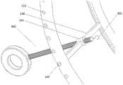
图1为本发明实施例中的跟骨骨折三维牵引复位装置的整体结构示意图;1 is a schematic diagram of the overall structure of a three-dimensional distraction reduction device for calcaneal fractures in an embodiment of the present invention;
图2为图1的局部放大示意图;Fig. 2 is the partial enlarged schematic diagram of Fig. 1;
图3为本发明实施例中的跟骨骨折三维牵引复位装置使用状态下的立体结构示意图;3 is a schematic three-dimensional structural diagram of a three-dimensional distraction reduction device for calcaneal fractures in an embodiment of the present invention in a state of use;
图4为本发明实施例中的跟骨骨折三维牵引复位装置使用状态下的主视示意图;4 is a schematic front view of the three-dimensional distraction reduction device for calcaneal fractures in an embodiment of the present invention in a state of use;
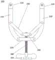
图5为本发明实施例中的跟骨骨折三维牵引复位装置的主视透视示意图;Fig. 5 is the front perspective schematic diagram of the three-dimensional distraction reduction device for calcaneal fracture in the embodiment of the present invention;
图6为本发明实施例中的跟骨骨折三维牵引复位装置中的复位双环和牵拉杆连接的整体结构示意图;6 is a schematic diagram of the overall structure of the connection between the reduction double ring and the traction rod in the three-dimensional distraction reduction device for calcaneal fractures according to the embodiment of the present invention;
图7为图6在固定件处的局部放大示意图;Fig. 7 is a partial enlarged schematic view of Fig. 6 at the fixing member;
图8为图6在一个牵拉杆处的局部放大示意图;Fig. 8 is a partial enlarged schematic view of Fig. 6 at a pull rod;
图9为本发明实施例中的跟骨骨折三维牵引复位装置中的滑动杆的整体结构示意图;9 is a schematic diagram of the overall structure of the sliding rod in the three-dimensional distraction reduction device for calcaneal fractures according to an embodiment of the present invention;
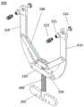
图10为本发明实施例中的跟骨骨折三维牵引复位装置中的牵引弓的整体结构示意图;10 is a schematic diagram of the overall structure of the distraction arch in the three-dimensional distraction reduction device for calcaneal fractures according to the embodiment of the present invention;
图11为本发明实施例中的跟骨骨折三维牵引复位装置中的牵引弓的主视示意图;11 is a schematic front view of a distraction arch in a three-dimensional distraction reduction device for calcaneal fractures according to an embodiment of the present invention;
图12为本发明实施例中的跟骨骨折三维牵引复位装置中的牵引弓的主视示意图(牵引弓张力相对图11增大);FIG. 12 is a schematic front view of the distraction arch in the three-dimensional distraction reduction device for calcaneal fractures according to the embodiment of the present invention (the tension of the distraction arch is increased compared to FIG. 11 );
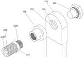
图13为本发明实施例中的跟骨骨折三维牵引复位装置中的牵引弓的在牵引针固定端的爆炸示意图;13 is an exploded schematic diagram of the distraction arch at the fixed end of the distraction pin in the three-dimensional distraction reduction device for calcaneal fractures according to the embodiment of the present invention;
图14为图13的局部放大示意图;Fig. 14 is a partial enlarged schematic view of Fig. 13;
图15为本发明实施例中的跟骨骨折三维牵引复位装置中的牵引弓中的转动环的整体结构示意图;15 is a schematic diagram of the overall structure of the rotating ring in the distraction arch in the three-dimensional distraction reduction device for calcaneal fractures according to the embodiment of the present invention;
图16为图15的剖面结构示意图。FIG. 16 is a schematic cross-sectional structure diagram of FIG. 15 .
图中,100、复位双环;110、环结构;111、滑动凹槽;112、槽口;113、限位孔;120、支撑杆;130、固定件;131、固定底座;132、旋紧螺母;133、第一贯穿孔;140、滑动杆;141、牵拉杆底座;142、滑动凸起;143、限位销;200、牵引弓;201、牵引针固定端;202、牵拉端;203、牵拉孔;210、弓臂;211、弓臂第一端;212、第二贯穿孔;213、转动槽;220、牵引针固定件;221、转动环;2211、转动环第一段;2212、转动环第二段;2213、牵引针孔;222、顶头;223、锁紧杆;2231、锁紧杆第一段;2232、锁紧杆第二段;2233、外六角;2234、内六角;230、第一连接板;240、连杆组;250、第二连接板;260、转动螺杆;300、牵拉杆;301、牵拉杆第一端。In the figure, 100, reset double ring; 110, ring structure; 111, sliding groove; 112, notch; 113, limit hole; 120, support rod; 130, fixing part; 131, fixing base; 132, tightening nut ; 133, the first through hole; 140, the sliding rod; 141, the pulling rod base; 142, the sliding protrusion; 143, the limit pin; 200, the traction bow; 201, the fixed end of the traction needle; 202, the pulling end; 203, the pulling hole; 210, the bow arm; 211, the first end of the bow arm; 212, the second through hole; 213, the rotation groove; ; 2212, the second section of the rotating ring; 2213, the pulling pinhole; 222, the plug; 223, the locking rod; 2231, the first section of the locking rod; 2232, the second section of the locking rod; 2233, the outer hexagon; 230, the first connecting plate; 240, the connecting rod group; 250, the second connecting plate; 260, the rotating screw; 300, the pulling rod; 301, the first end of the pulling rod.
具体实施方式Detailed ways
下面结合附图对本发明中的实施例进行具体的说明,部分结构未采用附图示出,本领域技术人员可以根据本发明的内容得出。The embodiments of the present invention will be described in detail below with reference to the accompanying drawings. Some structures are not shown in the accompanying drawings, but those skilled in the art can obtain from the content of the present invention.
本发明仅仅对进行了具体改进的部分做了详细的阐述,例如各部分的材质只要符合本发明的要求,可以采用市场上所可用的医用材料来制作,因此在此不做具体限定;本发明中其他本领域技术人员可以根据现有技术直接得到的部分在此不做具体阐述。The present invention only describes in detail the parts that have been specifically improved. For example, as long as the material of each part meets the requirements of the present invention, it can be made of medical materials available in the market, so it is not specifically limited here; Other parts of the system that can be directly obtained by those skilled in the art according to the prior art will not be described in detail here.
除非另有定义,本文所使用的所有的技术和科学术语与属于本发明的技术领域的技术人员通常理解的含义相同。本文中在本发明的说明书中所使用的术语只是为了描述具体的实施例的目的,不是旨在于限制本发明。本文所使用的术语“和/或”包括一个或多个相关的所列项目的任意的和所有的组合。Unless otherwise defined, all technical and scientific terms used herein have the same meaning as commonly understood by one of ordinary skill in the art to which this invention belongs. The terms used herein in the description of the present invention are for the purpose of describing specific embodiments only, and are not intended to limit the present invention. As used herein, the term "and/or" includes any and all combinations of one or more of the associated listed items.
实施例跟骨骨折三维牵引复位装置Example Three-dimensional distraction reduction device for calcaneal fractures
图1为本实施例中的跟骨骨折三维牵引复位装置的整体结构示意图,图2为图1的局部放大示意图,如图1-2所示,本实施例中的一种跟骨骨折三维牵引复位装置,包括复位双环100、牵引弓200和牵拉杆300;其中复位双环100包括相对间隔设置的两个环结构110,两个环结构110之间通过多个支撑杆120相连接,在复位双环100上设置有固定件130,固定件130对胫腓骨牵引针的两端进形固定;其中牵引弓200包括牵引针固定端201和牵拉端202;其中牵拉杆300设置于复位双环100上,牵拉杆第一端301伸入到两个双环结构110之间,牵拉杆第一端301与牵拉端202可拆卸连接,牵拉杆300在复位双环100上的连接位置和伸入到两个环结构110之间的长度均可调节。其中牵拉杆第二端伸出到到两个双环结构之外,并且在牵拉杆第二端设置有手柄结构。Fig. 1 is a schematic diagram of the overall structure of the three-dimensional distraction reduction device for calcaneal fractures in this embodiment, and Fig. 2 is a partial enlarged schematic diagram of Fig. 1. As shown in Figs. 1-2, a three-dimensional distraction for calcaneal fractures in this embodiment The reset device includes a reset
图3为本实施例中的跟骨骨折三维牵引复位装置使用状态下的立体结构示意图;图4为本实施例中的跟骨骨折三维牵引复位装置使用状态下的主视示意图;如图3-4所示,本实施例中的跟骨骨折三维牵引复位装置,在使用时患者脚部伸入到两个环结构110之间,其中的固定件130对固定于患者胫腓骨处的牵引针的两端进行固定,牵引弓200对患者脚部的其他部分的牵引针进行固定;通过调节其中牵拉杆300在复位双环100上的位置带动在环结构110上牵引弓200靠近或者远离固定件130,从而达到恢复跟骨角度的作用;通过调节牵拉杆300伸入到两个环结构110之间的长度带动牵引弓200向靠近或者远离环结构110中心位置,从而达到恢复跟骨的长度的作用;其中支撑件的设置使得复位装置整体结构稳定可靠;其中牵拉杆第一端301与牵拉端202可拆卸连接使得操作和使用更加方便;本实施例中的复位装置可以对跟骨骨折进行三维的牵引复位,通过对其中的牵拉杆300的调节可以精准控制牵引角度和力度,降低操作难度,节约人力。Figure 3 is a schematic diagram of the three-dimensional structure of the three-dimensional distraction and reduction device for calcaneal fractures in the present embodiment in use; Figure 4 is a schematic front view of the three-dimensional distraction and reduction device for calcaneal fractures in this embodiment; Figure 3- As shown in Fig. 4, the three-dimensional distraction reduction device for calcaneal fractures in this embodiment extends the patient's foot between the two
如图1-4所示,本实施例中的跟骨骨折三维牵引复位装置中的牵引弓200和牵拉杆300分别有两个,两个牵拉杆300在复位双环100上的位置与固定件130在复位双环100上的位置之间的连线呈三角形。设置有两个牵引弓200,两者分别对跗骨和跟骨结节处的牵引针进行固定,在使用时可以对跟骨长度和角度的调节更加方便,使得该复位装置对于形变严重,高能量损伤的复杂跟骨骨折的复位有很大优势。具体来说平方便复位,易于维持位置,减少软组织剥离。As shown in FIGS. 1-4 , there are two
当为了对其他性质的跟骨骨折进行牵引复位,可能选用不同数量的牵引弓200对其中的牵引针进行牵引,本领域技术人员可以根据需要进行设置,再此不做赘述。In order to perform distraction reduction for calcaneal fractures of other natures, different numbers of
如图1-4所示,环结构110整体为圆环,在两个环结构110之间还设置有两个滑动杆140,滑动杆140可以沿环结构110滑动并定位;每个牵拉杆300连接到一个滑动杆140上并朝向环结构110的中心处设置。通过设置滑动杆140实现牵拉杆300在环结构110上的位置的调节,结构简单便于实现。As shown in FIGS. 1-4 , the
本实施例中的环结构110为圆环,圆环结构110具有稳定性好的优点,同时与便于滑动杆140在环结构110上的滑动设置和滑动操作。当然本领域技术人员可以根据需要将环结构110设置为其他形状,例如环结构110可以为矩形环、三角形环、椭圆形环等。The
图5为本实施例中的跟骨骨折三维牵引复位装置的主视透视示意图,图6为本实施例中的跟骨骨折三维牵引复位装置中的复位双环100和牵拉杆300连接的整体结构示意图,如图1-6所示,本实施例中的两个环结构110通过三个支撑杆120连接,三个支撑杆120在环结构110上均匀设置;固定件130、两个滑动杆140分别设置于两个不同的支撑杆120之间。其中三个支撑杆120均匀是设置使得复位双环结构110稳定性好;并且其中固定件130和两个滑动杆140分开设置,从而使得牵引复位时复位双环100上相邻两个支撑杆120之间分别受力,使得牵拉复位过程中复位双环100受力均匀,进一步增强了复位双环100的稳定性。更为优选的,其中固定件130设置于两个支撑杆120之间的环结构110上的中间的位置,这样的设置使得两个支撑杆120对固定件130所固定的牵引针的受力分解更加均匀。FIG. 5 is a front perspective schematic diagram of the three-dimensional distraction and reduction device for calcaneal fractures in the present embodiment, and FIG. 6 is the overall structure of the connection between the reduction
图7为图6在固定件130处的局部放大示意图,如图7所示,本实施例中的固定件130包括分别设置两个环结构110上的固定底座131和旋紧螺母132,其中两个固定底座131在其相对的方向上分别设置有一个第一贯穿孔133,在两个固定底座131远离环结构110中心的一面上分别设置有一个螺纹孔,旋紧螺母132与螺纹孔进行螺纹配合;在使用时胫腓骨牵引针的两端分别伸入到两个第一贯穿孔133中,通过将旋紧螺母132旋向胫腓骨牵引针实现对其固定。本实施仅仅给出一个具体的结构,本领域中其他的牵引针固定结构只要与本发明其他部分没有冲突均可应用于本发明实现牵引针的固定,在此不做赘述。FIG. 7 is a partially enlarged schematic view of the fixing
图8为图6在一个牵拉杆300处的局部放大示意图;图9为本实施例中的跟骨骨折三维牵引复位装置中的滑动杆140的整体结构示意图。如图8-9所示,本实施还对其中的滑动杆140做了具体的设计,在滑动杆140上设置有牵拉杆底座141,牵拉杆底座141上设置有内螺纹,牵拉杆300外壁上设置有与内螺纹配合的外螺纹,通过旋转牵拉杆300实现所述牵拉杆300伸入两个环结构110之间的长度。通过牵拉底座上的内螺纹与牵拉杆300外周壁上的外螺纹的螺纹配合,实现了牵拉杆300在滑动杆140上的固定,并且只要通过旋转牵拉杆300就可以实现对牵拉杆300伸入到两个环结构110之间的长度进行调节,结构简单便于生产和操作。FIG. 8 is a partial enlarged schematic view of a
优选的,在每个滑动杆140的两端均设置有一个滑动凸起142,在两个环结构110上相对的位置上设置有两对用于容纳滑动凸起142的滑动凹槽111,滑动凹槽111相对的面上为允许滑动杆140滑动的槽口112。其中滑动凸起142与滑动凹槽111的设置可以实现滑动杆140在复位双环100上的位置的调节,结构简单,便于生产和操作。Preferably, a sliding
优选的,每个滑动杆140的至少一个滑动凸起142上设置有限位销143,环结构110上设置有多个与限位销143对应的限位孔113,限位孔113在环结构110上沿滑动凹槽111延伸的方向均匀设置;自然状态限位销143伸入限位孔113中实现滑动凸起142在滑动凹槽111中的定位,压动限位销143可实现滑动凸起142在滑动凹槽111中滑动。限位销143和多个限位孔113的设置实现了滑动杆140在复位双环100不同位置上的定位。本实施例中,在两个滑动凸起142上均设置有限位销143,这样使得滑动杆140的两端均可以得到限位,限位效果相对于尽在一侧的滑动凸起142上设置限位销143要更好一些。Preferably, at least one sliding
如图2和图8所示,本实施例中的牵拉杆第一端301为钩状结构,在牵引弓200的牵拉端202设置有牵拉孔203,本实施例中通过将钩状结构勾入牵拉孔203中实现牵拉杆第一端301与牵拉端202的可拆卸连接。牵引弓200和牵拉杆300之间通过牵引孔和钩状结构连接,结构简单使用方便。优选的,每个牵拉端202上均设置有多个牵拉孔203。多个牵拉孔203的设置,使得其中钩状结构牵拉不同的牵拉孔203可以调节牵拉角度。As shown in FIGS. 2 and 8 , the
本发明中的牵引弓200优选的为角度和张力可调节牵引弓200。选用角度和张力可调节的牵引弓200,使得牵引复位操作更加方便,效果更好。现有技术中的角度和张力可调节的牵引弓200只要其与本发明的基本构思没有冲突,均可适用于本发明,在此不做赘述。The
本实施还对其中的牵引弓200的具体结构做了具体的设计,图10为本实施例中的跟骨骨折三维牵引复位装置中的牵引弓200的整体结构示意图;图11为本实施例中的跟骨骨折三维牵引复位装置中的牵引弓200的主视示意图;图12为本实施例中的跟骨骨折三维牵引复位装置中的牵引弓200的主视示意图(牵引弓200张力相对图11增大)。In this embodiment, the specific structure of the
如图10-12所示,本实施例中的牵引弓200包括包括两个弧形的弓臂210,两个弓臂210的第一端上设置有牵引针固定件130,从而形成牵引针固定端201;两个弓臂210第二端分别与第一连接板230的两端可转动连接,两个弓臂210的中部分别可转动连接有一个连杆组240,两个连杆组240的另一端分别与第二连接板250的两端可转动连接,其中第一连接板230长度大于第二连接板250的长度;在第一连接板230上设置有垂直于第一连接板230的螺纹孔;牵引弓200还包括转动螺杆260,转动螺杆260通过第一连接板230上的螺纹孔与第一连接板230连接;转动螺杆260第一端连接到第二连接板250上,并且可以相对第二连接板250转动;其中转动螺杆260第二端为板装结构,其中牵引孔贯穿板状结构设置。在使用时,通过旋转其中的转动杆改变第一连接板230和第二连接板250之间的距离,从而改变弓臂第一端211上的牵引针固定件130之间的距离,从而实现牵引针的张力的调节。As shown in FIGS. 10-12 , the
优选的,还可以设置用于锁定转动螺杆260和第一连接板230的锁定结构(图中未示出),在转动螺杆260转动到需要的位置时对其进行锁定,从而使得牵引弓200的张力保持更好。Preferably, a locking structure (not shown in the figure) for locking the
图13为本实施例中的跟骨骨折三维牵引复位装置中的牵引弓200的在牵引针固定端201的爆炸示意图,图14为图13的局部放大示意图。FIG. 13 is an exploded schematic diagram of the
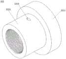
如图13-14所示,本实施例还对其中的牵引针固定件130做了具体的设计,如图13-14所示,本实施例中的牵引针固定件130包括整体为中空圆柱形的转动环221,图15为本实施例中的跟骨骨折三维牵引复位装置中的牵引弓200中的转动环221的整体结构示意图;图16为图15的剖面结构示意图。如图13-16所示,本实施例中的转动环221为两段式设置,其中转动环第一段2211的截面直径大于转动环第二段2212的截面直径;转动环第一段2211设置于弓臂第一端211内部,在弓臂第一端211上在垂直于两个弓臂210所在平面的方向上设置有第二贯穿孔212,围绕第二贯穿孔212设置有用于容纳转动环第一段2211的转动槽213,转动环第一段2211在转动槽213中可以转动;转动环第二段2212突出到弓臂第一端211外侧。在转动环第二段2212上设置有贯穿转动环221周壁的牵引针孔2213,牵引针孔2213通过中空圆柱轴线。用于其中转动环221可以转动,因此可以保证其中的牵引针孔2213可以跟着牵引针转动。As shown in FIGS. 13-14 , the traction
如图13-14所示,本实施例中的牵引针固定件130还包括顶头222和锁紧杆223,其中顶头222从弓臂第一端211远离转动环第二段2212的一侧连接到弓臂第一端211上,顶头222用于将中空圆柱填充到牵引针孔2213附近,用于承接牵引针避免其过分弯折,顶头222插入到中空圆柱的部分不影响转动环221的转动;其中锁紧杆第一段2231外壁上设置有外螺纹,在转动环第二段2212的内壁上设置有与锁紧杆第一段2231外壁上的外螺纹相配合的内螺纹,使用时锁紧杆第一段2231旋入转动环第二段2212中压紧穿入到牵引针孔2213的牵引针;其中锁紧杆第二段2232操作段,操作段的外周壁上设置有防滑条。另外,在锁紧杆223外周壁上还设置有外六角2233,在锁紧杆223的自由端的端部设置有下沉的内六角2234,内六角2234和外六角2233的设置便于使用扳手或者螺丝刀进行调节。As shown in FIGS. 13-14 , the traction
上述实施例的说明只是用于理解本发明。应当指出,对于本领域的普通技术人员来说,在不脱离本发明原理的前提下,还可以对本发明进行若干改进,这些改进也将落入本发明权利要求的保护范围内。The descriptions of the above-mentioned embodiments are only for understanding the present invention. It should be pointed out that for those of ordinary skill in the art, without departing from the principle of the present invention, several improvements can also be made to the present invention, and these improvements will also fall within the protection scope of the claims of the present invention.
Claims (10)
Priority Applications (1)
| Application Number | Priority Date | Filing Date | Title |
|---|---|---|---|
| CN202010983268.7ACN112022313B (en) | 2020-09-17 | 2020-09-17 | A three-dimensional distraction reduction device for calcaneal fractures |
Applications Claiming Priority (1)
| Application Number | Priority Date | Filing Date | Title |
|---|---|---|---|
| CN202010983268.7ACN112022313B (en) | 2020-09-17 | 2020-09-17 | A three-dimensional distraction reduction device for calcaneal fractures |
Publications (2)
| Publication Number | Publication Date |
|---|---|
| CN112022313Atrue CN112022313A (en) | 2020-12-04 |
| CN112022313B CN112022313B (en) | 2021-07-23 |
Family
ID=73573747
Family Applications (1)
| Application Number | Title | Priority Date | Filing Date |
|---|---|---|---|
| CN202010983268.7AActiveCN112022313B (en) | 2020-09-17 | 2020-09-17 | A three-dimensional distraction reduction device for calcaneal fractures |
Country Status (1)
| Country | Link |
|---|---|
| CN (1) | CN112022313B (en) |
Cited By (2)
| Publication number | Priority date | Publication date | Assignee | Title |
|---|---|---|---|---|
| CN112971961A (en)* | 2021-02-03 | 2021-06-18 | 山东大学齐鲁医院(青岛) | Elastic fixing guider for lower tibiofibular syndesmosis separation binding |
| CN113100896A (en)* | 2021-04-15 | 2021-07-13 | 山东大学齐鲁医院(青岛) | A closed reduction device for comminuted calcaneus fractures |
Citations (10)
| Publication number | Priority date | Publication date | Assignee | Title |
|---|---|---|---|---|
| SU1769871A1 (en)* | 1990-11-28 | 1992-10-23 | Oganes V Oganesyan | Apparatus for treatment of angle joint |
| CN2195926Y (en)* | 1994-06-07 | 1995-05-03 | 山东省文登市整骨医院 | Self-traction reduction fixer for calcaneal fracture |
| CN2471300Y (en)* | 2001-03-16 | 2002-01-16 | 李新军 | Reposition fixater for calcaneum fracture |
| US20040260223A1 (en)* | 2003-06-17 | 2004-12-23 | Roukis Thomas S. | External fixation device |
| RU2285487C2 (en)* | 2004-07-09 | 2006-10-20 | Научно-исследовательский центр Татарстана "Восстановительная травматология и ортопедия" | Apparatus for curing displaced fractures of heelbone |
| CN200963213Y (en)* | 2006-09-29 | 2007-10-24 | 李西成 | Automatic reposition device for calcaneum fracture |
| CN201295278Y (en)* | 2008-11-18 | 2009-08-26 | 刘三运 | Reposition fixater for calcaneum fracture |
| CN202723957U (en)* | 2012-08-13 | 2013-02-13 | 杨自兵 | Calcaneal fracture re-placing device |
| US20140257286A1 (en)* | 2009-10-05 | 2014-09-11 | Aalto University Foundation | Anatomically customized and mobilizing external support, method for manufacture |
| CN204863431U (en)* | 2015-07-01 | 2015-12-16 | 南阳市正骨医院 | Calcaneum resets and fixes draw gear with adjustable combination |
- 2020
- 2020-09-17CNCN202010983268.7Apatent/CN112022313B/enactiveActive
Patent Citations (10)
| Publication number | Priority date | Publication date | Assignee | Title |
|---|---|---|---|---|
| SU1769871A1 (en)* | 1990-11-28 | 1992-10-23 | Oganes V Oganesyan | Apparatus for treatment of angle joint |
| CN2195926Y (en)* | 1994-06-07 | 1995-05-03 | 山东省文登市整骨医院 | Self-traction reduction fixer for calcaneal fracture |
| CN2471300Y (en)* | 2001-03-16 | 2002-01-16 | 李新军 | Reposition fixater for calcaneum fracture |
| US20040260223A1 (en)* | 2003-06-17 | 2004-12-23 | Roukis Thomas S. | External fixation device |
| RU2285487C2 (en)* | 2004-07-09 | 2006-10-20 | Научно-исследовательский центр Татарстана "Восстановительная травматология и ортопедия" | Apparatus for curing displaced fractures of heelbone |
| CN200963213Y (en)* | 2006-09-29 | 2007-10-24 | 李西成 | Automatic reposition device for calcaneum fracture |
| CN201295278Y (en)* | 2008-11-18 | 2009-08-26 | 刘三运 | Reposition fixater for calcaneum fracture |
| US20140257286A1 (en)* | 2009-10-05 | 2014-09-11 | Aalto University Foundation | Anatomically customized and mobilizing external support, method for manufacture |
| CN202723957U (en)* | 2012-08-13 | 2013-02-13 | 杨自兵 | Calcaneal fracture re-placing device |
| CN204863431U (en)* | 2015-07-01 | 2015-12-16 | 南阳市正骨医院 | Calcaneum resets and fixes draw gear with adjustable combination |
Cited By (2)
| Publication number | Priority date | Publication date | Assignee | Title |
|---|---|---|---|---|
| CN112971961A (en)* | 2021-02-03 | 2021-06-18 | 山东大学齐鲁医院(青岛) | Elastic fixing guider for lower tibiofibular syndesmosis separation binding |
| CN113100896A (en)* | 2021-04-15 | 2021-07-13 | 山东大学齐鲁医院(青岛) | A closed reduction device for comminuted calcaneus fractures |
Also Published As
| Publication number | Publication date |
|---|---|
| CN112022313B (en) | 2021-07-23 |
Similar Documents
| Publication | Publication Date | Title |
|---|---|---|
| US8425512B2 (en) | Fixation device and multiple-axis joint for a fixation device | |
| US20070055234A1 (en) | External fixation system with provisional brace | |
| CN112022280B (en) | Clinical stone device of getting of hepatobiliary surgery | |
| JP2001293004A (en) | External fixation apparatus, high tibial ostectomy apparatus, ostectomy guide device and ostectomy method | |
| JP2005527314A (en) | Bone fixator with outrigger | |
| CN112022313A (en) | A three-dimensional distraction reduction device for calcaneal fractures | |
| CN109965960A (en) | A digital adjustable bone orthopedic external fixator with detachable motor | |
| CN111956315A (en) | Traction reduction device for tibia fracture coaptation operation | |
| CN217772477U (en) | External fixation support for moving transverse bones | |
| CN210009109U (en) | Auxiliary expanding device for spinal microscope operation | |
| CN221730846U (en) | An external fixator for correction of long bone deformity | |
| CN112773483A (en) | External fixing device for kirschner wire | |
| CN108938067B (en) | Cylinder Universal Reduction Device for Orthopedic Spine Surgery | |
| CN209864024U (en) | Reset pliers with sight | |
| CN213217525U (en) | A three-dimensional distraction reduction device for calcaneal fractures | |
| CN111956316A (en) | Traction reduction device for femoral fracture coaptation operation | |
| US20210275234A1 (en) | Device for correcting bone fractures | |
| CN110141336A (en) | An external fixator for skeletal rehabilitation with steplessly adjustable clamps | |
| CN201341941Y (en) | A fracture reposition instrument with multi-angle rotation and free expansion | |
| CN211633537U (en) | External fixing device for external adjustment of palm bone fracture reduction | |
| CN112451071A (en) | Universal traction distraction reduction support for minimally invasive tibiofibula fracture surgery | |
| CN1543915A (en) | Distal Radius Fracture External Fixator | |
| CN109044510B (en) | phalanx micro external fixator | |
| CN216455260U (en) | Fracture spreader and surgical medical device | |
| CN217310528U (en) | A device for intraoperative reduction of peri-ankle fractures |
Legal Events
| Date | Code | Title | Description |
|---|---|---|---|
| PB01 | Publication | ||
| PB01 | Publication | ||
| SE01 | Entry into force of request for substantive examination | ||
| SE01 | Entry into force of request for substantive examination | ||
| GR01 | Patent grant | ||
| GR01 | Patent grant |