CN112022227A - Coaxial trocar for fixing focus during percutaneous lung puncture biopsy - Google Patents
Coaxial trocar for fixing focus during percutaneous lung puncture biopsyDownload PDFInfo
- Publication number
- CN112022227A CN112022227ACN202010912254.6ACN202010912254ACN112022227ACN 112022227 ACN112022227 ACN 112022227ACN 202010912254 ACN202010912254 ACN 202010912254ACN 112022227 ACN112022227 ACN 112022227A
- Authority
- CN
- China
- Prior art keywords
- needle
- fixing
- base
- needle core
- sleeve
- Prior art date
- Legal status (The legal status is an assumption and is not a legal conclusion. Google has not performed a legal analysis and makes no representation as to the accuracy of the status listed.)
- Pending
Links
- 238000001574biopsyMethods0.000titleclaimsabstractdescription23
- 210000004072lungAnatomy0.000titleclaimsabstractdescription18
- 230000003902lesionEffects0.000claimsdescription25
- 230000007246mechanismEffects0.000claimsdescription8
- 230000005389magnetismEffects0.000claimsdescription5
- 238000010586diagramMethods0.000description9
- 238000000034methodMethods0.000description3
- 230000009471actionEffects0.000description2
- 230000000694effectsEffects0.000description2
- 238000003780insertionMethods0.000description2
- 230000037431insertionEffects0.000description2
- 238000002604ultrasonographyMethods0.000description2
- 230000009286beneficial effectEffects0.000description1
- 238000000605extractionMethods0.000description1
- 230000008569processEffects0.000description1
Images


Classifications
- A—HUMAN NECESSITIES
- A61—MEDICAL OR VETERINARY SCIENCE; HYGIENE
- A61B—DIAGNOSIS; SURGERY; IDENTIFICATION
- A61B17/00—Surgical instruments, devices or methods
- A61B17/34—Trocars; Puncturing needles
- A61B17/3403—Needle locating or guiding means
- A—HUMAN NECESSITIES
- A61—MEDICAL OR VETERINARY SCIENCE; HYGIENE
- A61B—DIAGNOSIS; SURGERY; IDENTIFICATION
- A61B10/00—Instruments for taking body samples for diagnostic purposes; Other methods or instruments for diagnosis, e.g. for vaccination diagnosis, sex determination or ovulation-period determination; Throat striking implements
- A61B10/02—Instruments for taking cell samples or for biopsy
- A61B10/0233—Pointed or sharp biopsy instruments
- A—HUMAN NECESSITIES
- A61—MEDICAL OR VETERINARY SCIENCE; HYGIENE
- A61B—DIAGNOSIS; SURGERY; IDENTIFICATION
- A61B17/00—Surgical instruments, devices or methods
- A61B17/34—Trocars; Puncturing needles
- A61B17/3417—Details of tips or shafts, e.g. grooves, expandable, bendable; Multiple coaxial sliding cannulas, e.g. for dilating
- A61B17/3421—Cannulas
- A—HUMAN NECESSITIES
- A61—MEDICAL OR VETERINARY SCIENCE; HYGIENE
- A61B—DIAGNOSIS; SURGERY; IDENTIFICATION
- A61B17/00—Surgical instruments, devices or methods
- A61B17/34—Trocars; Puncturing needles
- A61B17/3403—Needle locating or guiding means
- A61B2017/3413—Needle locating or guiding means guided by ultrasound
- A—HUMAN NECESSITIES
- A61—MEDICAL OR VETERINARY SCIENCE; HYGIENE
- A61B—DIAGNOSIS; SURGERY; IDENTIFICATION
- A61B17/00—Surgical instruments, devices or methods
- A61B17/34—Trocars; Puncturing needles
- A61B2017/348—Means for supporting the trocar against the body or retaining the trocar inside the body
- A61B2017/3492—Means for supporting the trocar against the body or retaining the trocar inside the body against the outside of the body
Landscapes
- Health & Medical Sciences (AREA)
- Life Sciences & Earth Sciences (AREA)
- Surgery (AREA)
- Medical Informatics (AREA)
- Engineering & Computer Science (AREA)
- Biomedical Technology (AREA)
- Heart & Thoracic Surgery (AREA)
- Pathology (AREA)
- Molecular Biology (AREA)
- Animal Behavior & Ethology (AREA)
- General Health & Medical Sciences (AREA)
- Public Health (AREA)
- Veterinary Medicine (AREA)
- Nuclear Medicine, Radiotherapy & Molecular Imaging (AREA)
- Infusion, Injection, And Reservoir Apparatuses (AREA)
- Surgical Instruments (AREA)
Abstract
Description
Translated fromChinese技术领域technical field
本发明涉及医疗器械技术领域,尤其涉及一种经皮肺穿刺活检时固定病灶的同轴套管针。The invention relates to the technical field of medical devices, in particular to a coaxial trocar for fixing lesions during percutaneous lung puncture biopsy.
背景技术Background technique
超声引导下经皮肺穿刺已被广泛应用于医疗工作,但是对于下肺的、较小的病灶,因活动度较大,忽隐忽现,就算活检穿刺针已插入病灶,也可能会滑脱,为超声引导下经皮穿刺的定位造成困难,易导致穿刺失败,同时增加并发症。Ultrasound-guided percutaneous lung puncture has been widely used in medical work, but for small lesions in the lower lung, due to the large activity, it may appear and disappear, even if the biopsy needle has been inserted into the lesion, it may slip off. This makes the positioning of percutaneous puncture under ultrasound guidance difficult, which can easily lead to puncture failure and increase complications.
发明内容SUMMARY OF THE INVENTION
(一)发明目的(1) Purpose of the invention
为解决背景技术中存在的技术问题,本发明提出一种经皮肺穿刺活检时固定病灶的同轴套管针。In order to solve the technical problems existing in the background art, the present invention proposes a coaxial trocar for fixing a lesion during percutaneous lung biopsy.
(二)技术方案(2) Technical solutions
为解决上述问题,本发明提供了一种经皮肺穿刺活检时固定病灶的同轴套管针,包括管套、针芯、固定装置;In order to solve the above problems, the present invention provides a coaxial trocar for fixing a lesion during percutaneous lung biopsy, including a tube sleeve, a needle core and a fixing device;
所述针芯在套管内可沿着套管的长度方向做进或出运动,所述固定装置设于套管内且可随针芯的运动方向同步运动;The needle core can move in or out in the cannula along the length direction of the cannula, and the fixing device is arranged in the cannula and can move synchronously with the movement direction of the needle core;
所述固定装置包括底座、与所述底座连接的固定针,所述套管上设有供固定针穿过的针孔,以及向固定针提供移动导向的滑槽;所述固定装置至少对称设置一组;The fixing device includes a base, a fixing needle connected with the base, a needle hole for the fixing needle to pass through on the sleeve, and a chute for providing movement guidance to the fixing needle; the fixing device is at least symmetrically arranged One group;
所述套管内壁设有限位块,用于在针芯做出运动时,对底座进行移动限位。The inner wall of the sleeve is provided with a limit block, which is used to limit the movement of the base when the needle core moves.
作为本发明的一个技术方案,对称设置的底座采用同磁性的磁块,所述针芯上设有与底座磁性相反的磁性区。As a technical solution of the present invention, the symmetrically arranged base adopts a magnetic block with the same magnetism, and the needle core is provided with a magnetic area opposite to the base magnetism.
作为本发明的一个技术方案,所述套管内位于所述限位块一侧设置有垫圈,所述垫圈的内径与针芯外径相适配。As a technical solution of the present invention, a washer is provided in the sleeve on one side of the limiting block, and the inner diameter of the washer is adapted to the outer diameter of the needle core.
作为本发明的一个技术方案,所述垫圈可与限位块一体成型。As a technical solution of the present invention, the washer can be integrally formed with the limiting block.
作为本发明的又一个技术方案,所述针芯上设有导向块和定位块,所述套管端部内壁设有与供所述导向块移动的导向槽A、导向槽B、导向槽C,所述导向槽A、导向槽B、导向槽C依次连接,所述底座上设有可与所述定位块进行卡合的卡口,以及与所述滑槽活动连接的连接杆,所述连接杆的端部设有滑动部,所述滑动部嵌入设置于滑槽内,且随着底座的移动而在滑槽内同步移动。As another technical solution of the present invention, the needle core is provided with a guide block and a positioning block, and the inner wall of the end of the sleeve is provided with a guide groove A, a guide groove B, and a guide groove C for the movement of the guide block. , the guide groove A, guide groove B, and guide groove C are connected in sequence, the base is provided with a bayonet that can be engaged with the positioning block, and a connecting rod movably connected with the chute, the The end of the connecting rod is provided with a sliding part, the sliding part is embedded in the chute, and moves synchronously in the chute along with the movement of the base.
优选的,所述滑动部与连接杆组合形成T形结构或L形结构,所述滑槽的滑动结构的形状与所述T形结构或L形结构相对应。Preferably, the sliding portion is combined with the connecting rod to form a T-shaped structure or an L-shaped structure, and the shape of the sliding structure of the sliding groove corresponds to the T-shaped structure or the L-shaped structure.
优选的,所述定位块包括但不限于卡合部与压紧部,所述卡合部可嵌入所述卡口内,在所述卡合部嵌入所述卡口内的状态下,所述压紧部与底座的上表面紧压贴合。Preferably, the positioning block includes but is not limited to an engaging portion and a pressing portion, the engaging portion can be embedded in the bayonet, and the pressing portion is in a state where the engaging portion is embedded in the bayonet. The part is tightly pressed against the upper surface of the base.
作为本发明的另一个技术方案,所述针芯上设有推动块,在所述针芯做进运动状态下,所述推动块推动底座与针芯同步运动,所述底座上设有与所述滑槽活动连接的连接杆,所述连接杆的端部设有滑动部,所述滑动部嵌入设置于滑槽内,且随着底座的移动而在滑槽内同步移动,所述滑动部与滑槽的端部之间通过弹性机构连接。As another technical solution of the present invention, a push block is provided on the needle core. When the needle core is in an advancing state, the push block pushes the base to move synchronously with the needle core. The connecting rod is movably connected with the chute, the end of the connecting rod is provided with a sliding part, the sliding part is embedded in the chute, and moves synchronously in the chute with the movement of the base, the sliding part It is connected with the end of the chute through an elastic mechanism.
优选的,所述弹性机构采用弹簧或弹片。Preferably, the elastic mechanism adopts a spring or an elastic sheet.
作为本发明的一个技术方案,所述固定针与底座之间弹性连接,用以使得固定针在沿滑槽长度方向移动时呈弹性压缩状态,在底座与限位块接触状态下呈自然状态。As a technical solution of the present invention, the fixed needle is elastically connected with the base, so that the fixed needle is in an elastically compressed state when moving along the length of the chute, and is in a natural state when the base is in contact with the limiting block.
本发明的上述技术方案具有如下有益的技术效果:The above-mentioned technical scheme of the present invention has the following beneficial technical effects:
本发明使得超声引导下经皮穿刺的定位更为稳定,有效提高了穿刺的成功率,同时有效避免并发症的发生。The invention makes the positioning of percutaneous puncture under the guidance of ultrasound more stable, effectively improves the success rate of puncture, and at the same time effectively avoids the occurrence of complications.
附图说明Description of drawings
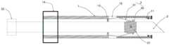
图1为本发明一实施例中针芯做进运动一种状态下结构示意图;FIG. 1 is a schematic structural diagram of the needle core in a state of advancing motion in an embodiment of the present invention;
图2为本发明一实施例中针芯做出运动一种状态下结构示意图;2 is a schematic structural diagram of a state in which the needle core moves in an embodiment of the present invention;
图3为本发明又一实施例结构示意图;3 is a schematic structural diagram of another embodiment of the present invention;
图4为本发明一实施例中局部结构示意图;4 is a schematic diagram of a partial structure in an embodiment of the present invention;
图5为本图3中定位块结构示意图;FIG. 5 is a schematic structural diagram of the positioning block in FIG. 3;
图6为本发明一实施例中底座局部结构示意图;6 is a schematic diagram of a partial structure of a base in an embodiment of the present invention;
图7为本发明一实施例中滑槽局部结构示意图;7 is a schematic diagram of a partial structure of a chute in an embodiment of the present invention;
图8为本发明另一实施例结构示意图;8 is a schematic structural diagram of another embodiment of the present invention;
图9为本发明图8所示实施例中针芯做出运动一种状态下结构示意图。FIG. 9 is a schematic structural diagram in a state in which the needle core moves in the embodiment shown in FIG. 8 of the present invention.
标注说明:Label description:
1、套管;11、滑槽;12、针孔;13、限位块;14、管尾;15、垫圈;16、导向槽A;17、导向槽B;18、导向槽C;2、针芯;21、磁性区;22、针尾;23、导向块;24、定位块;241、卡合部;242、压紧部;25、推动块;3、固定装置;31、固定针;32、底座;321、卡口;33、连接杆;331、滑动部;4、弹性机构。1. Sleeve; 11. Chute; 12. Pinhole; 13. Limiting block; 14. Pipe end; 15. Washer; 16. Guide groove A; 17. Guide groove B; 18. Guide groove C; 2. needle core; 21, magnetic area; 22, needle tail; 23, guide block; 24, positioning block; 241, engaging part; 242, pressing part; 25, push block; 3, fixing device; 31, fixing needle; 32, base; 321, bayonet; 33, connecting rod; 331, sliding part; 4, elastic mechanism.
具体实施方式Detailed ways
为使本发明的目的、技术方案和优点更加清楚明了,下面结合具体实施方式并参照附图,对本发明进一步详细说明。应该理解,这些描述只是示例性的,而并非要限制本发明的范围。此外,在以下说明中,省略了对公知结构和技术的描述,以避免不必要地混淆本发明的概念。In order to make the objectives, technical solutions and advantages of the present invention clearer, the present invention will be further described in detail below with reference to the specific embodiments and the accompanying drawings. It should be understood that these descriptions are exemplary only and are not intended to limit the scope of the invention. Also, in the following description, descriptions of well-known structures and techniques are omitted to avoid unnecessarily obscuring the concepts of the present invention.
本发明将针芯2与套管1一同插入病灶,然后将可针芯2抽出,利用固定装置3将管套1固定于病灶,套管1中可以置入相应的活检针进行活检取材,活检结束,针芯2再次置入套管1内,解除套管1的固定,从而将套管1与针芯2一同抽出,退出病灶。In the present invention, the
如图1-9所示,本发明提出的一种经皮肺穿刺活检时固定病灶的同轴套管针,包括管套1、针芯2、固定装置3;As shown in FIGS. 1-9 , a coaxial trocar for fixing lesions during percutaneous lung biopsy proposed by the present invention includes a cannula 1 , a
所述针芯2在套管1内可沿着套管1的长度方向做进或出运动,所述固定装置3设于套管1内且可随针芯2的运动方向同步运动;The
所述固定装置3包括底座32、与所述底座32连接的固定针31,所述套管1上设有供固定针31穿过的针孔12,以及向固定针31提供移动导向的滑槽11;所述固定装置3至少对称设置一组,以下实施例中以一组两个固定装置3为例。The fixing device 3 includes a
所述套管1内壁设有限位块13,用于在针芯2做出运动时,对底座32进行移动限位。The inner wall of the cannula 1 is provided with a
在一个实施例中,对称设置的底座32采用同磁性的磁块,所述针芯2上设有与底座32磁性相反的磁性区21。In one embodiment, the symmetrically arranged
在本实施例中,当针芯2插入套管1内,磁性区21由于与两个对称设置的底座32磁性相反,故而,当底座32与针芯2上的磁性区21接触时,两者相吸合,此时,固定装置3会随针芯2的运动而同步发生运动。针芯2继续做进运动时,固定装置3同步做进运动,即固定针31沿着滑槽11的长度方向进行移动,可实现套管1与针芯2同步插入病灶内;抽出针芯2,固定装置3与针芯2同步做出运动,固定针31在滑槽11内退出,通过套管1上的针孔12穿出。针芯2继续做出运动,由于限位块13的作用,底座32与针芯2上的磁性区21脱离,针芯2抽出,由于对称的底座32磁性相同,会相互排斥,使得固定针31固定于针孔12位置,从而使得套管1固定于病灶。再次插入针芯2,当磁性区21与底座32接触时,带动固定针31与针芯同步发生移动,随着针芯2的移动,固定针31脱离针孔12,继而可以一同于病灶内抽出套管。In this embodiment, when the
需要说明的是,固定针31与底座32之间弹性连接,用以使得固定针31在沿滑槽11长度方向移动时呈弹性压缩状态,在底座32与限位块13接触状态下呈自然状态。仅仅作为示例而言,但不限于此示例。例如固定针31与底座32之间通过扭簧连接,以实现上述功能。It should be noted that the elastic connection between the fixed
为了能够是的再针芯2插入下进行导向,避免针芯2端部触碰到限位块13造成伸入阻挡。In order to allow the
套管1内位于所述限位块13一侧设置有垫圈15,所述垫圈15的内径与针芯2外径相适配。A
进一步的可以理解的是,所述垫圈15可与限位块13一体成型。It can be further understood that the
在此方案下,仍能理解的是,垫圈15、限位块13与套管1内壁可一体成型。Under this solution, it can still be understood that the
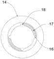
在又一个实施例中,所述针芯2上设有导向块23和定位块24,所述套管2端部内壁设有与供所述导向块23移动的导向槽A16、导向槽B17、导向槽C18,所述导向槽A16、导向槽B17、导向槽C18依次连接,所述底座32上设有可与所述定位块24进行卡合的卡口321,以及与所述滑槽11活动连接的连接杆33,所述连接杆33的端部设有滑动部331,所述滑动部331嵌入设置于滑槽11内,且随着底座32的移动而在滑槽11内同步移动。In yet another embodiment, the
本实施例是通过针芯2插入套管1内后,转动针芯2使得定位块24与底座32上的卡口321卡合,再推动针芯2带动底座32同步运动的方式,带动固定针31沿滑槽11长度方向进行运动。In this embodiment, after the
因此,可以理解的是,定位块24、导向块23位于针芯2上位置有一定的限定。作为示例,导向槽A16、导向槽B17、导向槽C18依次连接,形成“匸”字形结构,故而,定位块24与卡口321之间的距离,应与导向槽B17的长度相适配,鉴于此,导向块23在进入导向槽A16后,转动进入导向槽B17,且移动到导向槽B17端部时,定位块24可恰好与卡口321卡合。Therefore, it can be understood that the positions of the
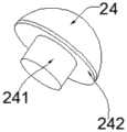
进一步的是,定位块24包括但不限于卡合部241与压紧部242,所述卡合部241可嵌入所述卡口321内,在所述卡合部241嵌入所述卡口321内的状态下,所述压紧部242与底座32的上表面紧压贴合。Further, the
即,定位块24与卡口321卡合状态下,卡合部241嵌入卡口321内,而压紧部242与底座32的上表面紧压。That is, when the
在上述定位块24与卡口321卡合状态下,移动针芯2,可带动底座32同步运动,即带动固定针31同步运动。In the state where the
抽出针芯2的过程中,当底座32与限位块13接触时,固定针31穿出针孔12,转动反向针芯2,使得定位块24脱离卡口321,抽出时,需要再次转动针芯2,使得导向块23的位置与导向槽C18位置对应,即可抽出针芯2,固定针31将套管1固定于病灶,套管1中可以置入相应的活检针进行活检取材。拔出套管1的操作同上,再此不做赘述。During the process of pulling out the
为了更好的实现连接杆33的将底座32固定再套管1内,和实现连接杆33更好的在滑槽11内滑动,即方便底座32随针芯2的运动而同步运动的目的。In order to better realize the connecting
进一步的优选的是,所述滑动部331与连接杆33组合形成T形结构或L形结构,所述滑槽11的滑动结构的形状与所述T形结构或L形结构相对应。Further preferably, the sliding
在另一个实施例中,所述针芯2上设有推动块25,在所述针芯2做进运动状态下,所述推动块25推动底座32与针芯2同步运动,所述底座32上设有与所述滑槽11活动连接的连接杆33,所述连接杆33的端部设有滑动部331,所述滑动部331嵌入设置于滑槽11内,且随着底座32的移动而在滑槽11内同步移动,所述滑动部331与滑槽11的端部之间通过弹性机构4连接。In another embodiment, the
优选的是,所述弹性机构4采用弹簧或弹片。Preferably, the
在本实施例中,仅仅作为实例而言,弹性机构4采用弹簧时,可以理解的是,弹簧在自然状态下,固定针31恰好穿出针孔12。In this embodiment, only as an example, when the
那么,进一步可理解的是,当针芯2插入套管1做进运动时,推动快25与底座32接触后,推动底座32,在滑槽11的作用下使得底座32跟随连接杆33同步运动,从而使得固定针31沿滑槽11的长度方向同步运动,将套管1与针芯2插入病灶,抽出针芯2,即针芯2做出运动时,弹簧逐渐复位,直至推动快25与底座32分离,弹簧处于自然状态,固定针31穿出针孔12,将套管1固定于病灶。此后,套管1中可以置入相应的活检针进行活检取材。再次插入针芯2,同理使得固定针31脱离针孔12后,便可将针芯2余套管1同步抽出。Then, it can be further understood that when the
在上述的实施例中,为了避免针芯2插入过度,在针芯2的尾部设有针尾22,针尾22的宽度大于套管1的内径。In the above-mentioned embodiment, in order to avoid excessive insertion of the
为了方便套管1的抽出,在套管1的尾部设有管尾14。In order to facilitate the extraction of the casing 1 , a
鉴于上述实施例,能理解的是,可通过扎带捆扎或连接片连接的方式,使得多根套管1连接在一起进行使用。In view of the above-mentioned embodiments, it can be understood that a plurality of sleeves 1 can be connected together for use by bundling with a cable tie or connecting with a connecting piece.
以上显示和描述了本发明的基本原理、主要特征和本发明的优点。本行业的技术人员应该了解,本发明不受上述实施例的限制,上述实施例和说明书中描述的仅为本发明的优选例,并不用来限制本发明,在不脱离本发明精神和范围的前提下,本发明还会有各种变化和改进,这些变化和改进都落入要求保护的本发明范围内。本发明要求保护范围由所附的权利要求书及其等效物界定。The foregoing has shown and described the basic principles, main features and advantages of the present invention. Those skilled in the art should understand that the present invention is not limited by the above-mentioned embodiments, and the above-mentioned embodiments and descriptions are only preferred examples of the present invention, and are not intended to limit the present invention, without departing from the spirit and scope of the present invention. Under the premise, the present invention will also have various changes and improvements, and these changes and improvements all fall within the scope of the claimed invention. The claimed scope of the present invention is defined by the appended claims and their equivalents.
Claims (10)
Translated fromChineseApplications Claiming Priority (2)
| Application Number | Priority Date | Filing Date | Title |
|---|---|---|---|
| CN202010577625 | 2020-06-23 | ||
| CN202010577625X | 2020-06-23 |
Publications (1)
| Publication Number | Publication Date |
|---|---|
| CN112022227Atrue CN112022227A (en) | 2020-12-04 |
Family
ID=73591646
Family Applications (2)
| Application Number | Title | Priority Date | Filing Date |
|---|---|---|---|
| CN202021889781.1UActiveCN212698975U (en) | 2020-06-23 | 2020-09-02 | Coaxial trocar for fixing focus during percutaneous lung puncture biopsy |
| CN202010912254.6APendingCN112022227A (en) | 2020-06-23 | 2020-09-02 | Coaxial trocar for fixing focus during percutaneous lung puncture biopsy |
Family Applications Before (1)
| Application Number | Title | Priority Date | Filing Date |
|---|---|---|---|
| CN202021889781.1UActiveCN212698975U (en) | 2020-06-23 | 2020-09-02 | Coaxial trocar for fixing focus during percutaneous lung puncture biopsy |
Country Status (1)
| Country | Link |
|---|---|
| CN (2) | CN212698975U (en) |
Cited By (1)
| Publication number | Priority date | Publication date | Assignee | Title |
|---|---|---|---|---|
| CN113413173A (en)* | 2021-07-08 | 2021-09-21 | 王倩倩 | Cervical lesion tissue cell curettage device |
Families Citing this family (1)
| Publication number | Priority date | Publication date | Assignee | Title |
|---|---|---|---|---|
| CN212698975U (en)* | 2020-06-23 | 2021-03-16 | 上海市肺科医院 | Coaxial trocar for fixing focus during percutaneous lung puncture biopsy |
Citations (13)
| Publication number | Priority date | Publication date | Assignee | Title |
|---|---|---|---|---|
| US4790329A (en)* | 1987-06-12 | 1988-12-13 | Trustees Of Beth Israel Hospital | Adjustable biopsy localization device |
| US4931059A (en)* | 1986-11-24 | 1990-06-05 | Markham Charles W | Needle/stylet combination |
| DE19500009A1 (en)* | 1993-12-31 | 1995-07-20 | Storz Karl | Trocar esp. for medical purposes |
| US20070078397A1 (en)* | 2005-09-15 | 2007-04-05 | Weststrate Patrice A | Access needle well-suited for percutaneous implantation in a body lumen |
| US20090099521A1 (en)* | 2007-10-16 | 2009-04-16 | Peter Gravesen | Cannula Insertion Device and Related Methods |
| US20090105659A1 (en)* | 2007-10-17 | 2009-04-23 | Tyco Healthcare Group Lp | Anchoring cannula |
| US20100105981A1 (en)* | 2008-10-27 | 2010-04-29 | Ovesco Endoscopy Ag | Puncturing Instrument |
| US20130102967A1 (en)* | 2011-10-21 | 2013-04-25 | Synergetics, Inc. | Magnetic Trocar System |
| CN103239276A (en)* | 2013-05-20 | 2013-08-14 | 凌立君 | Minimally invasive puncture positioning needle |
| CN104334091A (en)* | 2012-06-21 | 2015-02-04 | 奥林巴斯株式会社 | Access port |
| US20150297260A1 (en)* | 2012-11-20 | 2015-10-22 | Trokasure Gbr | Trocar device and use thereof |
| US20180161545A1 (en)* | 2002-09-20 | 2018-06-14 | Interrad Medical, Inc. | Temporary retention device |
| CN212698975U (en)* | 2020-06-23 | 2021-03-16 | 上海市肺科医院 | Coaxial trocar for fixing focus during percutaneous lung puncture biopsy |
- 2020
- 2020-09-02CNCN202021889781.1Upatent/CN212698975U/enactiveActive
- 2020-09-02CNCN202010912254.6Apatent/CN112022227A/enactivePending
Patent Citations (13)
| Publication number | Priority date | Publication date | Assignee | Title |
|---|---|---|---|---|
| US4931059A (en)* | 1986-11-24 | 1990-06-05 | Markham Charles W | Needle/stylet combination |
| US4790329A (en)* | 1987-06-12 | 1988-12-13 | Trustees Of Beth Israel Hospital | Adjustable biopsy localization device |
| DE19500009A1 (en)* | 1993-12-31 | 1995-07-20 | Storz Karl | Trocar esp. for medical purposes |
| US20180161545A1 (en)* | 2002-09-20 | 2018-06-14 | Interrad Medical, Inc. | Temporary retention device |
| US20070078397A1 (en)* | 2005-09-15 | 2007-04-05 | Weststrate Patrice A | Access needle well-suited for percutaneous implantation in a body lumen |
| US20090099521A1 (en)* | 2007-10-16 | 2009-04-16 | Peter Gravesen | Cannula Insertion Device and Related Methods |
| US20090105659A1 (en)* | 2007-10-17 | 2009-04-23 | Tyco Healthcare Group Lp | Anchoring cannula |
| US20100105981A1 (en)* | 2008-10-27 | 2010-04-29 | Ovesco Endoscopy Ag | Puncturing Instrument |
| US20130102967A1 (en)* | 2011-10-21 | 2013-04-25 | Synergetics, Inc. | Magnetic Trocar System |
| CN104334091A (en)* | 2012-06-21 | 2015-02-04 | 奥林巴斯株式会社 | Access port |
| US20150297260A1 (en)* | 2012-11-20 | 2015-10-22 | Trokasure Gbr | Trocar device and use thereof |
| CN103239276A (en)* | 2013-05-20 | 2013-08-14 | 凌立君 | Minimally invasive puncture positioning needle |
| CN212698975U (en)* | 2020-06-23 | 2021-03-16 | 上海市肺科医院 | Coaxial trocar for fixing focus during percutaneous lung puncture biopsy |
Cited By (1)
| Publication number | Priority date | Publication date | Assignee | Title |
|---|---|---|---|---|
| CN113413173A (en)* | 2021-07-08 | 2021-09-21 | 王倩倩 | Cervical lesion tissue cell curettage device |
Also Published As
| Publication number | Publication date |
|---|---|
| CN212698975U (en) | 2021-03-16 |
Similar Documents
| Publication | Publication Date | Title |
|---|---|---|
| US6918881B2 (en) | Biopsy needle with integrated guide pin | |
| US8167819B2 (en) | Biopsy needle with integrated guide pin | |
| CN112022227A (en) | Coaxial trocar for fixing focus during percutaneous lung puncture biopsy | |
| JPS60182939A (en) | Prostate biopsy needle through rectum | |
| US9968340B2 (en) | Biopsy device with automatic aspiration | |
| WO2020052484A1 (en) | Calculus removing mesh basket and double-cavity end cap for calculus removing mesh basket | |
| CN108379719A (en) | Micro-invasive drainage device | |
| JP2000175930A (en) | Paracentesis treating implement | |
| CN203388888U (en) | Biopsy device | |
| CN209360757U (en) | For the pipe sheath structure through bronchoscopic biopsies needle | |
| CN109498120B (en) | Laparoscopic poke card puncture system | |
| US10524833B2 (en) | Device and methods for precise control of medical procedures | |
| CN219629676U (en) | Ultrasonic guided thyroid puncture needle | |
| CN212522038U (en) | A marker for deep lesions and its delivery device | |
| CN219021460U (en) | Surgical laparoscope sleeve | |
| CN204274584U (en) | A kind of cicatrix pregnancy special puncture outfit | |
| CN217138120U (en) | Puncture needle for cytology examination | |
| CN209004015U (en) | A variable-angle endoscopic venous blood collection device | |
| CN1079226C (en) | Automatic synchronous negative-pressure sampling device for biopsy | |
| CN203564276U (en) | Automatic mucosa marking biopsy forceps | |
| CN209122480U (en) | Flexible and retrievable puncture anchor and its fixator | |
| CN215821006U (en) | Disposable negative pressure biopsy needle that endocrinology department used | |
| CN212679769U (en) | an indwelling needle | |
| CN221888343U (en) | A puncture needle that is easy to position | |
| CN222870549U (en) | Ultrasonic aspiration biopsy needle |
Legal Events
| Date | Code | Title | Description |
|---|---|---|---|
| PB01 | Publication | ||
| PB01 | Publication | ||
| SE01 | Entry into force of request for substantive examination | ||
| SE01 | Entry into force of request for substantive examination |