CN112021866A - a bed structure - Google Patents
a bed structureDownload PDFInfo
- Publication number
- CN112021866A CN112021866ACN202010997609.6ACN202010997609ACN112021866ACN 112021866 ACN112021866 ACN 112021866ACN 202010997609 ACN202010997609 ACN 202010997609ACN 112021866 ACN112021866 ACN 112021866A
- Authority
- CN
- China
- Prior art keywords
- frame
- bed structure
- polygonal frame
- structure according
- rod
- Prior art date
- Legal status (The legal status is an assumption and is not a legal conclusion. Google has not performed a legal analysis and makes no representation as to the accuracy of the status listed.)
- Pending
Links
Images


Classifications
- A—HUMAN NECESSITIES
- A47—FURNITURE; DOMESTIC ARTICLES OR APPLIANCES; COFFEE MILLS; SPICE MILLS; SUCTION CLEANERS IN GENERAL
- A47D—FURNITURE SPECIALLY ADAPTED FOR CHILDREN
- A47D7/00—Children's beds
- A47D7/002—Children's beds foldable
- A—HUMAN NECESSITIES
- A47—FURNITURE; DOMESTIC ARTICLES OR APPLIANCES; COFFEE MILLS; SPICE MILLS; SUCTION CLEANERS IN GENERAL
- A47D—FURNITURE SPECIALLY ADAPTED FOR CHILDREN
- A47D13/00—Other nursery furniture
- A47D13/06—Children's play- pens
- A47D13/061—Children's play- pens foldable
- A—HUMAN NECESSITIES
- A47—FURNITURE; DOMESTIC ARTICLES OR APPLIANCES; COFFEE MILLS; SPICE MILLS; SUCTION CLEANERS IN GENERAL
- A47D—FURNITURE SPECIALLY ADAPTED FOR CHILDREN
- A47D15/00—Accessories for children's furniture, e.g. safety belts or baby-bottle holders
- A—HUMAN NECESSITIES
- A47—FURNITURE; DOMESTIC ARTICLES OR APPLIANCES; COFFEE MILLS; SPICE MILLS; SUCTION CLEANERS IN GENERAL
- A47D—FURNITURE SPECIALLY ADAPTED FOR CHILDREN
- A47D9/00—Cradles ; Bassinets
- A47D9/005—Cradles ; Bassinets foldable
- A—HUMAN NECESSITIES
- A47—FURNITURE; DOMESTIC ARTICLES OR APPLIANCES; COFFEE MILLS; SPICE MILLS; SUCTION CLEANERS IN GENERAL
- A47D—FURNITURE SPECIALLY ADAPTED FOR CHILDREN
- A47D9/00—Cradles ; Bassinets
- A47D9/02—Cradles ; Bassinets with rocking mechanisms
Landscapes
- Health & Medical Sciences (AREA)
- General Health & Medical Sciences (AREA)
- Pediatric Medicine (AREA)
- Special Chairs (AREA)
Abstract
Description
Translated fromChinese技术领域technical field
本发明涉及一种床结构。The present invention relates to a bed structure.
背景技术Background technique
儿童在成长的过程中,需要用到婴儿床、游戏围栏床等各种床结构,这些床结构占据的空间较大,无法收纳成较小的状态,不便于存放和携带。而且这些床结构功能单一,导致需要配置不同种类的床结构来达到满足相应的使用需求,造成使用成本较高,并且占据较多的家居空间。In the process of growth, children need to use various bed structures such as cribs and playpen beds. These bed structures occupy a large space and cannot be stored in a smaller state, which is not convenient for storage and carrying. Moreover, these beds have a single structure and function, which leads to the need to configure different types of bed structures to meet the corresponding use requirements, resulting in higher use costs and occupying more home space.
发明内容SUMMARY OF THE INVENTION
本发明旨在至少解决现有技术中存在的技术问题之一。为此,本发明提出一种收纳后体积较小、方便携带和运输的床结构。The present invention aims to solve at least one of the technical problems existing in the prior art. To this end, the present invention proposes a bed structure that is small in volume after storage, and is convenient to carry and transport.
根据本发明实施例的一种床结构,包括:多边形框架,所述多边形框架包括至少两个相互平行的伸缩杆,所述多边形框架跟随所述伸缩杆伸缩变化而具有展开状态和收缩状态,所述多边形框架上转动连接有能够支撑所述多边形框架的支脚,所述支脚可转动收纳至收缩状态的所述多边形框架之内,所述多边形框架上可拆卸安装有开口向上的储存篮。A bed structure according to an embodiment of the present invention includes: a polygonal frame, the polygonal frame includes at least two mutually parallel telescopic rods, and the polygonal frame has an expanded state and a contracted state following the telescopic changes of the telescopic rods, so The polygon frame is rotatably connected with legs capable of supporting the polygon frame, the legs can be rotatably stored in the polygon frame in a retracted state, and a storage basket with an upward opening is detachably installed on the polygon frame.
根据本发明实施例的床结构,至少具有如下有益效果:The bed structure according to the embodiment of the present invention has at least the following beneficial effects:
本发明实施例的床结构在收纳时,将储物篮从多边形框架上拆除,然后将多边形框架上的伸缩杆收缩以使多变形框架缩小,各个支脚转动后收纳在收缩状态的多边形框架之内,从而将床结构收叠成扁平状,极大程度地减小存放空间,方便携带和运输。When the bed structure of the embodiment of the present invention is stored, the storage basket is removed from the polygonal frame, and then the telescopic rods on the polygonal frame are contracted to shrink the polymorphic frame, and each leg is rotated and stored in the contracted polygonal frame. , so that the bed structure is folded into a flat shape, the storage space is greatly reduced, and it is convenient to carry and transport.
在本发明的一些实施例中,所述多边形框架为矩形框架,所述矩形框架包括两条长杆和两条宽杆,所述长杆和/或所述宽杆为所述伸缩杆,所述矩形框架的四个边角处分别转动连接有一个所述支脚。In some embodiments of the present invention, the polygonal frame is a rectangular frame, the rectangular frame includes two long rods and two wide rods, the long rods and/or the wide rods are the telescopic rods, so The four corners of the rectangular frame are respectively rotatably connected with one of the supporting feet.
在本发明的一些实施例中,所述支脚与所述矩形框架之间设有用于锁定所述支脚的展开角度的弹性自锁机构。In some embodiments of the present invention, an elastic self-locking mechanism for locking the expansion angle of the support leg is provided between the support leg and the rectangular frame.
在本发明的一些实施例中,所述弹性自锁机构包括滑动设置在所述支脚上的滑块,所述滑块上设有定位凸部,所述矩形框架上设有与所述定位凸部相对应的定位凹槽,所述支脚与所述滑块之间设有驱使所述滑块靠近所述矩形框架的第一弹性件,所述支脚展开时,所述第一弹性件可驱使所述定位凸部移动至所述定位凹槽之内。In some embodiments of the present invention, the elastic self-locking mechanism includes a sliding block slidably arranged on the support feet, the sliding block is provided with a positioning protrusion, and the rectangular frame is provided with a positioning protrusion corresponding to the positioning protrusion. There is a positioning groove corresponding to the part, and a first elastic member that drives the slider to be close to the rectangular frame is provided between the support foot and the slider. When the support foot is unfolded, the first elastic member can drive the slider The positioning protrusion moves into the positioning groove.
在本发明的一些实施例中,位于所述宽杆两端的两个所述支脚之间可拆卸安装有一摇杆,所述摇杆具有与地面相接触的弧形段。In some embodiments of the present invention, a rocker is detachably installed between the two feet located at both ends of the wide rod, and the rocker has an arc-shaped section that contacts the ground.
在本发明的一些实施例中,所述摇杆上设有与所述弧形段的两端相连的安装接头,所述安装接头上设有向上延伸的插柱,所述支脚的底面上开设有与所述插柱相配合的插孔,所述插柱的表面上设有一圈防脱凹槽,所述支脚的侧壁上活动设置有沿所述插孔的径向伸缩运动的防脱卡片,所述防脱卡片上设有供所述插柱穿过的穿孔,所述防脱卡片连接有驱使所述穿孔的内侧壁抵靠在所述防脱凹槽的侧面的第二弹性件。In some embodiments of the present invention, the rocker is provided with installation joints connected to both ends of the arc-shaped segment, the installation joint is provided with an upwardly extending post, and the bottom surface of the support foot is provided with There is a socket matched with the socket, a ring of anti-drop grooves is arranged on the surface of the socket, and the side wall of the support foot is movably provided with anti-drop-off movement along the radial direction of the socket. A card, the slip-proof card is provided with a perforation for the insertion post to pass through, and the slip-proof card is connected with a second elastic member that urges the inner side wall of the perforation to abut against the side of the slip-proof groove .
在本发明的一些实施例中,所述储存篮由柔性编织物构成,所述储存篮的开口边缘与所述多边形框架相连,所述支脚上设有至少一个能够将所述储存篮的底部拉直的连接组件。In some embodiments of the present invention, the storage basket is made of flexible woven fabric, the open edge of the storage basket is connected to the polygonal frame, and the feet are provided with at least one piece capable of pulling the bottom of the storage basket Straight connection components.
在本发明的一些实施例中,所述支脚的中部和底部分别设置有一个所述连接组件,所述连接组件包括枢接在所述支脚上的连接座和连接于所述连接座与所述储存篮的底部之间的连接带。In some embodiments of the present invention, the middle part and the bottom of the support foot are respectively provided with one of the connecting components, and the connecting component includes a connecting seat pivotally connected to the support foot and a connecting seat connected to the connecting seat and the Attachment straps between the bottoms of the storage baskets.
在本发明的一些实施例中,所述伸缩杆包括内杆和活动套装在所述内杆外部的外杆,所述内杆和所述外杆的其一上沿其长度方向间隔分布有至少两个档位孔,所述内杆和所述外杆的另一上设有可与任一所述档位孔相结合的弹珠结构。In some embodiments of the present invention, the telescopic rod includes an inner rod and an outer rod movably sheathed outside the inner rod, and one of the inner rod and the outer rod is spaced along its length direction with at least There are two gear holes, and the other one of the inner rod and the outer rod is provided with a marble structure that can be combined with any of the gear holes.
在本发明的一些实施例中,所述支脚包括转动连接在所述多边形框架上的支管和伸缩设置在所述支管下端的单元管。In some embodiments of the present invention, the support feet include a branch pipe rotatably connected to the polygonal frame and a unit pipe telescopically arranged at the lower end of the branch pipe.
本发明的附加方面和优点将在下面的描述中部分给出,部分将从下面的描述中变得明显,或通过本发明的实践了解到。Additional aspects and advantages of the present invention will be set forth, in part, from the following description, and in part will be apparent from the following description, or may be learned by practice of the invention.
附图说明Description of drawings
本发明的上述和/或附加的方面和优点从结合下面附图对实施例的描述中将变得明显和容易理解,其中:The above and/or additional aspects and advantages of the present invention will become apparent and readily understood from the following description of embodiments taken in conjunction with the accompanying drawings, wherein:
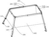
图1为本发明的床结构处于展开状态的一种实施例的结构示意图;1 is a schematic structural diagram of an embodiment of the bed structure of the present invention in an unfolded state;
图2为本发明的床结构处于展开状态的另一种实施例的结构示意图;2 is a schematic structural diagram of another embodiment of the bed structure of the present invention in an unfolded state;
图3为图1或者图2实施例的床结构处于收缩状态的结构示意图;3 is a schematic structural diagram of the bed structure of the embodiment of FIG. 1 or FIG. 2 in a contracted state;
图4是图1实施例的弹性自锁机构与支脚和多边形框架相分离的结构分解示意图;4 is a schematic exploded view of the structure of the elastic self-locking mechanism of the embodiment of FIG. 1 separated from the legs and the polygonal frame;
图5是具有摇杆的床结构的一个实施例的结构示意图;Figure 5 is a schematic structural diagram of an embodiment of a bed structure with a rocker;
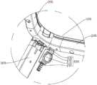
图6是图5实施例的摇杆与支脚相分离的结构分解示意图。FIG. 6 is a schematic exploded view of the structure in which the rocker and the support feet are separated in the embodiment of FIG. 5 .
具体实施方式Detailed ways
下面详细描述本发明的实施例,所述实施例的示例在附图中示出,其中自始至终相同或类似的标号表示相同或类似的元件或具有相同或类似功能的元件。下面通过参考附图描述的实施例是示例性的,仅用于解释本发明,而不能理解为对本发明的限制。The following describes in detail the embodiments of the present invention, examples of which are illustrated in the accompanying drawings, wherein the same or similar reference numerals refer to the same or similar elements or elements having the same or similar functions throughout. The embodiments described below with reference to the accompanying drawings are exemplary, only used to explain the present invention, and should not be construed as a limitation of the present invention.
在本发明的描述中,需要理解的是,涉及到方位描述,例如术语“上”、“下”、“前”、“后”、“左”、“右”、“竖直”、“水平”、“顶”、“底”、“内”、“外”等指示的方位或位置关系为基于附图所示的方位或位置关系,仅是为了便于描述本发明和简化描述,而不是指示或暗示所指的装置或元件必须具有特定的方位、以特定的方位构造和操作,因此不能理解为对本发明的限制。In the description of the present invention, it should be understood that orientation descriptions are involved, such as the terms "upper", "lower", "front", "rear", "left", "right", "vertical", "horizontal" "," "top", "bottom", "inside", "outside" and other indicated orientations or positional relationships are based on the orientations or positional relationships shown in the accompanying drawings, which are only for the convenience of describing the present invention and simplifying the description, rather than indicating Or imply that the device or element referred to must have a particular orientation, be constructed and operate in a particular orientation, and therefore should not be construed as limiting the invention.
在本发明的描述中,若干的含义是一个或者多个,多个的含义是两个以上,大于、小于、超过等理解为不包括本数,以上、以下、以内等理解为包括本数。如果有描述到第一、第二只是用于区分技术特征为目的,而不能理解为指示或暗示相对重要性或者隐含指明所指示的技术特征的数量或者隐含指明所指示的技术特征的先后关系。In the description of the present invention, the meaning of several is one or more, the meaning of multiple is two or more, greater than, less than, exceeding, etc. are understood as not including this number, above, below, within, etc. are understood as including this number. If it is described that the first and the second are only for the purpose of distinguishing technical features, it cannot be understood as indicating or implying relative importance, or indicating the number of the indicated technical features or the order of the indicated technical features. relation.
本发明的描述中,需要说明的是,除非另有明确的规定和限定,术语“安装”、“相连”、“连接”应做广义理解,例如,可以是固定连接,也可以是可拆卸连接,或一体地连接;可以是机械连接,也可以是电连接;可以是直接相连,也可以通过中间媒介间接相连,可以是两个元件内部的连通。对于本领域的普通技术人员而言,可以具体情况理解上述术语在本发明中的具体含义。In the description of the present invention, it should be noted that, unless otherwise expressly specified and limited, the terms "installation", "connection" and "connection" should be understood in a broad sense, for example, it may be a fixed connection or a detachable connection , or integrally connected; it can be a mechanical connection or an electrical connection; it can be a direct connection, or an indirect connection through an intermediate medium, or the internal communication between the two components. For those of ordinary skill in the art, the specific meanings of the above terms in the present invention can be understood in specific situations.
参见图1和图3,一种床结构,包括:多边形框架100,所述多边形框架100包括至少两个相互平行的伸缩杆200,所述多边形框架100跟随所述伸缩杆200伸缩变化而具有展开状态和收缩状态,多边形框架100能够沿着伸缩杆200的伸长方向拉伸达到展开状态,或者能够沿着伸缩杆200的缩短方向收缩达到收缩状态,所述多边形框架100上转动连接有能够支撑多边形框架100的支脚300,在展开状态下,所有支脚300与地面接触而形成稳定的支撑结构,所述支脚300可转动收纳至收缩状态的所述多边形框架100之内,所述多边形框架100上可拆卸安装有开口向上的储存篮600,其中储存篮600供儿童或者婴儿进行躺卧或者站立。本发明实施例的床结构在收纳时,将储物篮从多边形框架100上拆除,然后将多边形框架100上的伸缩杆200收缩以使多变形框架缩小,各个支脚300转动后收纳在收缩状态的多边形框架100之内,从而将床结构收叠成扁平状,极大程度地减小存放空间,方便携带和运输。1 and 3, a bed structure includes: a
参见图1和图2,在本发明的一些实施例中,所述多边形框架100为矩形框架,所述矩形框架包括两条长杆和两条宽杆,所述长杆和/或所述宽杆为所述伸缩杆200,所述矩形框架的四个边角处分别转动连接有一个所述支脚300。优选地,长杆和宽杆均为伸缩杆200,其中,在一些实施例中,伸缩杆200包括内杆210和活动套装在所述内杆210外部的外杆220,所述内杆210和所述外杆220的其一上沿其长度方向间隔分布有至少两个档位孔,所述内杆210和所述外杆220的另一上设有可与任一所述档位孔相结合的弹珠结构。1 and 2, in some embodiments of the present invention, the
参见图3和图4,在本发明的一些实施例中,所述支脚300与所述矩形框架之间设有用于锁定所述支脚300的展开角度的弹性自锁机构400,弹性自锁机构400可以实现支脚300展开后快速固定,避免支脚300受到外力发生进一步转动。Referring to FIG. 3 and FIG. 4 , in some embodiments of the present invention, an elastic self-
在本发明的一些实施例中,所述弹性自锁机构400包括滑动设置在所述支脚300上的滑块410,所述滑块410上设有定位凸部420,所述矩形框架上设有与所述定位凸部420相对应的定位凹槽430,所述支脚300与所述滑块410之间设有驱使所述滑块410靠近所述矩形框架的第一弹性件440,所述支脚300展开时,所述第一弹性件440可驱使所述定位凸部420移动至所述定位凹槽430之内,从而将支脚300固定。当需要折叠收纳本发明的床结构时,推动滑块410使得定位凸部420脱离定位凹槽430,然后转动支脚300至矩形框架之内。In some embodiments of the present invention, the elastic self-
参见图5,在本发明的一些实施例中,位于所述宽杆两端的两个所述支脚300之间可拆卸安装有一摇杆500,所述摇杆500具有与地面相接触的弧形段。此时,带有摇杆500的床结构可作婴儿摇床使用,进一步扩展本发明的床结构的功能。Referring to FIG. 5 , in some embodiments of the present invention, a
参见图6,在本发明的一些实施例中,所述摇杆500上设有与所述弧形段的两端相连的安装接头510,所述安装接头510上设有向上延伸的插柱520,所述支脚300的底面上开设有与所述插柱520相配合的插孔310,所述插柱520的表面上设有一圈防脱凹槽521,所述支脚300的侧壁上活动设置有沿所述插孔310的径向伸缩运动的防脱卡片320,所述防脱卡片320上设有供所述插柱520穿过的穿孔321,所述防脱卡片320连接有驱使所述穿孔321的内侧壁抵靠在所述防脱凹槽521的侧面的第二弹性件330。当摇杆500上的插柱520插入插孔310时,防脱卡片320上的穿孔321的内侧壁在第二弹性件330的作用下抵靠防脱凹槽521上而防止摇杆500向下脱离;当需要拆卸摇杆500时,朝向第二弹性件330的形变方向施力而使得穿孔321与防脱凹槽521相分离,进而将插柱520从插孔310向外拔出。Referring to FIG. 6 , in some embodiments of the present invention, the
在本发明的一些实施例中,所述储存篮600由柔性编织物构成,例如网布、棉布等等,所述储存篮600的开口边缘与所述多边形框架相连,所述支脚300上设有至少一个能够将所述储存篮600的底部拉直的连接组件340。其中,所述支脚300的中部和底部分别设置有一个所述连接组件340,所述连接组件340包括枢接在所述支脚300上的连接座和连接于所述连接座与所述储存篮600的底部之间的连接带。参见图1,所有的位于支脚300中部的连接组件340与储存篮600的底部的四个边角相连而使床结构可作婴儿床使用,参见图2,所有的位于支脚300底部的连接组件340与储存篮600的底部的四个边角相连而使储存篮600的底部可以与地面接触,小孩可以站立在储存篮600内活动,该床结构可作游戏围床使用。In some embodiments of the present invention, the
在本发明的一些实施例中,为了实现床结构的升降功能,所述支脚300包括转动连接在所述多边形框架100上的支管301和伸缩设置在所述支管301下端的单元管302。In some embodiments of the present invention, in order to realize the lifting function of the bed structure, the supporting
以上所述实施例的各技术特征可以进行任意的组合,为使描述简洁,未对上述实施例中的各个技术特征所有可能的组合都进行描述,然而,只要这些技术特征的组合不存在矛盾,都应当认为是本说明书记载的范围。The technical features of the above-described embodiments can be combined arbitrarily. For the sake of brevity, all possible combinations of the technical features in the above-described embodiments are not described. However, as long as there is no contradiction between the combinations of these technical features, All should be regarded as the scope described in this specification.
尽管已经示出和描述了本发明的实施例,本领域的普通技术人员可以理解:在不脱离本发明的原理和宗旨的情况下可以对这些实施例进行多种变化、修改、替换和变型,本发明的范围由权利要求及其等同物限定。Although embodiments of the present invention have been shown and described, it will be understood by those of ordinary skill in the art that various changes, modifications, substitutions and alterations can be made in these embodiments without departing from the principles and spirit of the invention, The scope of the invention is defined by the claims and their equivalents.
Claims (10)
Translated fromChinesePriority Applications (1)
| Application Number | Priority Date | Filing Date | Title |
|---|---|---|---|
| CN202010997609.6ACN112021866A (en) | 2020-09-21 | 2020-09-21 | a bed structure |
Applications Claiming Priority (1)
| Application Number | Priority Date | Filing Date | Title |
|---|---|---|---|
| CN202010997609.6ACN112021866A (en) | 2020-09-21 | 2020-09-21 | a bed structure |
Publications (1)
| Publication Number | Publication Date |
|---|---|
| CN112021866Atrue CN112021866A (en) | 2020-12-04 |
Family
ID=73574750
Family Applications (1)
| Application Number | Title | Priority Date | Filing Date |
|---|---|---|---|
| CN202010997609.6APendingCN112021866A (en) | 2020-09-21 | 2020-09-21 | a bed structure |
Country Status (1)
| Country | Link |
|---|---|
| CN (1) | CN112021866A (en) |
Cited By (1)
| Publication number | Priority date | Publication date | Assignee | Title |
|---|---|---|---|---|
| CN115807984A (en)* | 2022-12-21 | 2023-03-17 | 珠海格力电器股份有限公司 | Air conditioning unit, and sinking device and sinking method of fan assembly |
Citations (9)
| Publication number | Priority date | Publication date | Assignee | Title |
|---|---|---|---|---|
| GB469703A (en)* | 1936-09-16 | 1937-07-30 | Eileen Mavis Pimbury | Adjustable cradle |
| CN1281670A (en)* | 1999-07-26 | 2001-01-31 | 中山市隆成日用制品有限公司 | Playpen combined with toddler cot |
| CN101198271A (en)* | 2005-06-14 | 2008-06-11 | 比约恩婴儿用品公司 | A child's bed |
| CN106419306A (en)* | 2016-11-18 | 2017-02-22 | 卡贝乐(厦门)儿童用品有限公司 | Foldable baby cot |
| CN206062698U (en)* | 2016-07-08 | 2017-04-05 | 好孩子儿童用品有限公司 | A kind of folding bed |
| CN107518685A (en)* | 2017-10-12 | 2017-12-29 | 东莞硕仕儿童用品有限公司 | A kind of foldable baby crib |
| CN209202511U (en)* | 2018-08-01 | 2019-08-06 | 好孩子儿童用品有限公司 | Swingable travelling bed |
| CN110169676A (en)* | 2018-02-20 | 2019-08-27 | 明门瑞士股份有限公司 | foldable children bed |
| CN212591288U (en)* | 2020-09-21 | 2021-02-26 | 兔迪昵(厦门)贸易有限公司 | Bed structure |
- 2020
- 2020-09-21CNCN202010997609.6Apatent/CN112021866A/enactivePending
Patent Citations (9)
| Publication number | Priority date | Publication date | Assignee | Title |
|---|---|---|---|---|
| GB469703A (en)* | 1936-09-16 | 1937-07-30 | Eileen Mavis Pimbury | Adjustable cradle |
| CN1281670A (en)* | 1999-07-26 | 2001-01-31 | 中山市隆成日用制品有限公司 | Playpen combined with toddler cot |
| CN101198271A (en)* | 2005-06-14 | 2008-06-11 | 比约恩婴儿用品公司 | A child's bed |
| CN206062698U (en)* | 2016-07-08 | 2017-04-05 | 好孩子儿童用品有限公司 | A kind of folding bed |
| CN106419306A (en)* | 2016-11-18 | 2017-02-22 | 卡贝乐(厦门)儿童用品有限公司 | Foldable baby cot |
| CN107518685A (en)* | 2017-10-12 | 2017-12-29 | 东莞硕仕儿童用品有限公司 | A kind of foldable baby crib |
| CN110169676A (en)* | 2018-02-20 | 2019-08-27 | 明门瑞士股份有限公司 | foldable children bed |
| CN209202511U (en)* | 2018-08-01 | 2019-08-06 | 好孩子儿童用品有限公司 | Swingable travelling bed |
| CN212591288U (en)* | 2020-09-21 | 2021-02-26 | 兔迪昵(厦门)贸易有限公司 | Bed structure |
Cited By (1)
| Publication number | Priority date | Publication date | Assignee | Title |
|---|---|---|---|---|
| CN115807984A (en)* | 2022-12-21 | 2023-03-17 | 珠海格力电器股份有限公司 | Air conditioning unit, and sinking device and sinking method of fan assembly |
Similar Documents
| Publication | Publication Date | Title |
|---|---|---|
| CN108720435B (en) | game bed | |
| EP3669703B1 (en) | One-button folding bedstead and game bed | |
| JPH0746196Y2 (en) | Foldable baby bed | |
| CN2922647Y (en) | crib | |
| TW202222214A (en) | Child bassinet | |
| CN103960917B (en) | Infant support device | |
| US20230329451A1 (en) | Topper accessories for a playard | |
| US12408764B2 (en) | Bassinet accessory for a playard | |
| CN204445034U (en) | For the mattress in children's accommodating device | |
| CN110192743A (en) | game bed | |
| CN210870581U (en) | A folding chair leg bracket | |
| CN219147154U (en) | Multipurpose folding leg and multipurpose folding leg module | |
| CN112021866A (en) | a bed structure | |
| US6725475B1 (en) | Foldable mechanism for a base of playyard | |
| CN108209317A (en) | A kind of lower folding device of child play bed | |
| JP2025010401A (en) | Bed Frame Structure | |
| CN104510224A (en) | Baby bedstead and baby crib | |
| CN214760236U (en) | Bedside bed | |
| CN212591288U (en) | Bed structure | |
| CN211608908U (en) | Children dining chair | |
| JP3176222U (en) | Portable toilet frame | |
| US6625826B1 (en) | Safety device for foldable baby bed | |
| CN213097171U (en) | Foldable baby crib | |
| CN114947446A (en) | Double-posture electric storage bedstead | |
| US2946459A (en) | Collapsible shelf structure |
Legal Events
| Date | Code | Title | Description |
|---|---|---|---|
| PB01 | Publication | ||
| PB01 | Publication | ||
| SE01 | Entry into force of request for substantive examination | ||
| SE01 | Entry into force of request for substantive examination |