CN112020593B - Ported casing collar for downhole operations and method for accessing a formation - Google Patents
Ported casing collar for downhole operations and method for accessing a formationDownload PDFInfo
- Publication number
- CN112020593B CN112020593BCN201980018789.4ACN201980018789ACN112020593BCN 112020593 BCN112020593 BCN 112020593BCN 201980018789 ACN201980018789 ACN 201980018789ACN 112020593 BCN112020593 BCN 112020593B
- Authority
- CN
- China
- Prior art keywords
- sleeve
- inner sleeve
- outer sleeve
- setting tool
- wellbore
- Prior art date
- Legal status (The legal status is an assumption and is not a legal conclusion. Google has not performed a legal analysis and makes no representation as to the accuracy of the status listed.)
- Active
Links
- 238000000034methodMethods0.000titleclaimsabstractdescription118
- 230000015572biosynthetic processEffects0.000titleclaimsabstractdescription98
- 239000011435rockSubstances0.000claimsabstractdescription48
- 239000011159matrix materialSubstances0.000claimsabstractdescription29
- 239000012530fluidSubstances0.000claimsdescription174
- 239000007921spraySubstances0.000claimsdescription160
- 238000004519manufacturing processMethods0.000claimsdescription124
- 230000035939shockEffects0.000claimsdescription57
- 229930195733hydrocarbonNatural products0.000claimsdescription36
- 150000002430hydrocarbonsChemical class0.000claimsdescription36
- 238000006073displacement reactionMethods0.000claimsdescription33
- 230000033001locomotionEffects0.000claimsdescription31
- 239000004215Carbon black (E152)Substances0.000claimsdescription30
- 241000282472Canis lupus familiarisSpecies0.000claimsdescription25
- 230000005484gravityEffects0.000claimsdescription18
- 238000011144upstream manufacturingMethods0.000claimsdescription15
- 230000013011matingEffects0.000claimsdescription7
- 230000008878couplingEffects0.000claimsdescription6
- 238000010168coupling processMethods0.000claimsdescription6
- 238000005859coupling reactionMethods0.000claimsdescription6
- 239000013598vectorSubstances0.000claimsdescription6
- 238000007789sealingMethods0.000claimsdescription4
- 238000010008shearingMethods0.000claimsdescription4
- 230000003213activating effectEffects0.000claims2
- 206010017076FractureDiseases0.000description108
- 208000010392Bone FracturesDiseases0.000description96
- 238000005755formation reactionMethods0.000description94
- XQCFHQBGMWUEMY-ZPUQHVIOSA-NNitrovinChemical compoundC=1C=C([N+]([O-])=O)OC=1\C=C\C(=NNC(=N)N)\C=C\C1=CC=C([N+]([O-])=O)O1XQCFHQBGMWUEMY-ZPUQHVIOSA-N0.000description72
- 238000002347injectionMethods0.000description72
- 239000007924injectionSubstances0.000description72
- 238000005553drillingMethods0.000description38
- 230000035882stressEffects0.000description31
- 230000000638stimulationEffects0.000description28
- 238000005086pumpingMethods0.000description25
- 239000007789gasSubstances0.000description22
- 230000007246mechanismEffects0.000description18
- 238000011282treatmentMethods0.000description18
- VNWKTOKETHGBQD-UHFFFAOYSA-NmethaneChemical compoundCVNWKTOKETHGBQD-UHFFFAOYSA-N0.000description16
- 239000006163transport mediaSubstances0.000description15
- 239000011148porous materialSubstances0.000description14
- 230000007704transitionEffects0.000description14
- 239000002253acidSubstances0.000description12
- 230000008901benefitEffects0.000description12
- 238000000926separation methodMethods0.000description12
- 210000001015abdomenAnatomy0.000description10
- 239000011162core materialSubstances0.000description10
- 238000013461designMethods0.000description10
- 230000001976improved effectEffects0.000description10
- 230000008569processEffects0.000description10
- XLYOFNOQVPJJNP-UHFFFAOYSA-NwaterSubstancesOXLYOFNOQVPJJNP-UHFFFAOYSA-N0.000description10
- 230000006870functionEffects0.000description9
- 238000009826distributionMethods0.000description8
- 238000011065in-situ storageMethods0.000description8
- 239000007788liquidSubstances0.000description8
- 239000004568cementSubstances0.000description7
- 230000006378damageEffects0.000description7
- 239000003795chemical substances by applicationSubstances0.000description6
- 238000004891communicationMethods0.000description6
- 230000003628erosive effectEffects0.000description6
- 238000002955isolationMethods0.000description6
- 239000003345natural gasSubstances0.000description6
- 230000009467reductionEffects0.000description6
- 239000007787solidSubstances0.000description6
- 230000003313weakening effectEffects0.000description6
- 238000013459approachMethods0.000description5
- 230000009286beneficial effectEffects0.000description5
- 230000000694effectsEffects0.000description5
- 238000005516engineering processMethods0.000description5
- 238000005259measurementMethods0.000description5
- 230000035699permeabilityEffects0.000description5
- 238000011084recoveryMethods0.000description5
- 230000001276controlling effectEffects0.000description4
- 239000002609mediumSubstances0.000description4
- 238000012544monitoring processMethods0.000description4
- 239000000047productSubstances0.000description4
- 230000001105regulatory effectEffects0.000description4
- 229910000831SteelInorganic materials0.000description3
- 239000000654additiveSubstances0.000description3
- 230000000712assemblyEffects0.000description3
- 238000000429assemblyMethods0.000description3
- 238000009412basement excavationMethods0.000description3
- 238000004364calculation methodMethods0.000description3
- 238000007596consolidation processMethods0.000description3
- 238000010586diagramMethods0.000description3
- 239000000835fiberSubstances0.000description3
- 230000000977initiatory effectEffects0.000description3
- 239000002245particleSubstances0.000description3
- 230000035515penetrationEffects0.000description3
- 229920001343polytetrafluoroethylenePolymers0.000description3
- 239000004810polytetrafluoroethyleneSubstances0.000description3
- 238000002360preparation methodMethods0.000description3
- 239000010959steelSubstances0.000description3
- 230000004936stimulating effectEffects0.000description3
- IJGRMHOSHXDMSA-UHFFFAOYSA-NAtomic nitrogenChemical compoundN#NIJGRMHOSHXDMSA-UHFFFAOYSA-N0.000description2
- 208000006670Multiple fracturesDiseases0.000description2
- 229920006362Teflon®Polymers0.000description2
- 230000009471actionEffects0.000description2
- 230000003190augmentative effectEffects0.000description2
- 239000006227byproductSubstances0.000description2
- 230000008859changeEffects0.000description2
- 238000004140cleaningMethods0.000description2
- 239000003245coalSubstances0.000description2
- -1condensateSubstances0.000description2
- 230000007423decreaseEffects0.000description2
- 230000009977dual effectEffects0.000description2
- 239000013505freshwaterSubstances0.000description2
- 239000000446fuelSubstances0.000description2
- 230000004048modificationEffects0.000description2
- 238000012986modificationMethods0.000description2
- 238000003032molecular dockingMethods0.000description2
- 230000001681protective effectEffects0.000description2
- 230000002829reductive effectEffects0.000description2
- 230000002787reinforcementEffects0.000description2
- 238000009877renderingMethods0.000description2
- 230000008439repair processEffects0.000description2
- 230000004044responseEffects0.000description2
- 239000000523sampleSubstances0.000description2
- 239000004576sandSubstances0.000description2
- 239000000243solutionSubstances0.000description2
- 238000005507sprayingMethods0.000description2
- 239000000126substanceSubstances0.000description2
- OKTJSMMVPCPJKN-UHFFFAOYSA-NCarbonChemical compound[C]OKTJSMMVPCPJKN-UHFFFAOYSA-N0.000description1
- BVKZGUZCCUSVTD-UHFFFAOYSA-LCarbonateChemical compound[O-]C([O-])=OBVKZGUZCCUSVTD-UHFFFAOYSA-L0.000description1
- UFHFLCQGNIYNRP-UHFFFAOYSA-NHydrogenChemical compound[H][H]UFHFLCQGNIYNRP-UHFFFAOYSA-N0.000description1
- 229920000271Kevlar®Polymers0.000description1
- 235000015076Shorea robustaNutrition0.000description1
- 244000166071Shorea robustaSpecies0.000description1
- 239000003082abrasive agentSubstances0.000description1
- 238000010306acid treatmentMethods0.000description1
- 230000032683agingEffects0.000description1
- 239000010426asphaltSubstances0.000description1
- 230000004888barrier functionEffects0.000description1
- 230000009172burstingEffects0.000description1
- 229910052799carbonInorganic materials0.000description1
- 230000015556catabolic processEffects0.000description1
- 230000005465channelingEffects0.000description1
- 239000002131composite materialSubstances0.000description1
- 230000006835compressionEffects0.000description1
- 238000007906compressionMethods0.000description1
- 238000012790confirmationMethods0.000description1
- 239000000470constituentSubstances0.000description1
- 238000010276constructionMethods0.000description1
- 238000011109contaminationMethods0.000description1
- 238000010924continuous productionMethods0.000description1
- 230000007797corrosionEffects0.000description1
- 238000005260corrosionMethods0.000description1
- 238000007405data analysisMethods0.000description1
- 230000003247decreasing effectEffects0.000description1
- 238000006731degradation reactionMethods0.000description1
- 230000000779depleting effectEffects0.000description1
- 230000008021depositionEffects0.000description1
- 230000001066destructive effectEffects0.000description1
- 238000001514detection methodMethods0.000description1
- 238000011161developmentMethods0.000description1
- 230000018109developmental processEffects0.000description1
- 238000004090dissolutionMethods0.000description1
- 238000009429electrical wiringMethods0.000description1
- 239000004744fabricSubstances0.000description1
- 239000000706filtrateSubstances0.000description1
- 230000004907fluxEffects0.000description1
- 125000001475halogen functional groupChemical group0.000description1
- 239000001257hydrogenSubstances0.000description1
- 229910052739hydrogenInorganic materials0.000description1
- 238000003384imaging methodMethods0.000description1
- 230000004941influxEffects0.000description1
- 238000003780insertionMethods0.000description1
- 230000037431insertionEffects0.000description1
- 230000002452interceptive effectEffects0.000description1
- 239000004761kevlarSubstances0.000description1
- 230000002147killing effectEffects0.000description1
- 230000000670limiting effectEffects0.000description1
- 238000005461lubricationMethods0.000description1
- 239000000463materialSubstances0.000description1
- 230000005012migrationEffects0.000description1
- 238000013508migrationMethods0.000description1
- 238000003801millingMethods0.000description1
- 230000003278mimic effectEffects0.000description1
- 239000000203mixtureSubstances0.000description1
- 229910052757nitrogenInorganic materials0.000description1
- 239000013307optical fiberSubstances0.000description1
- 238000005457optimizationMethods0.000description1
- 150000002894organic compoundsChemical class0.000description1
- 230000020477pH reductionEffects0.000description1
- 238000012856packingMethods0.000description1
- 239000003208petroleumSubstances0.000description1
- 230000003449preventive effectEffects0.000description1
- 238000012545processingMethods0.000description1
- 230000002250progressing effectEffects0.000description1
- 230000002062proliferating effectEffects0.000description1
- 230000001902propagating effectEffects0.000description1
- 239000000376reactantSubstances0.000description1
- 238000010223real-time analysisMethods0.000description1
- 230000002441reversible effectEffects0.000description1
- 238000000518rheometryMethods0.000description1
- 230000000630rising effectEffects0.000description1
- 239000003079shale oilSubstances0.000description1
- 238000004513sizingMethods0.000description1
- 230000003068static effectEffects0.000description1
- 230000008093supporting effectEffects0.000description1
- 238000010408sweepingMethods0.000description1
- 208000024891symptomDiseases0.000description1
- 239000010409thin filmSubstances0.000description1
- 230000009466transformationEffects0.000description1
- 238000013519translationMethods0.000description1
- 238000009966trimmingMethods0.000description1
- 239000011800void materialSubstances0.000description1
Images


Classifications
- E—FIXED CONSTRUCTIONS
- E21—EARTH OR ROCK DRILLING; MINING
- E21B—EARTH OR ROCK DRILLING; OBTAINING OIL, GAS, WATER, SOLUBLE OR MELTABLE MATERIALS OR A SLURRY OF MINERALS FROM WELLS
- E21B7/00—Special methods or apparatus for drilling
- E21B7/04—Directional drilling
- E21B7/06—Deflecting the direction of boreholes
- E21B7/061—Deflecting the direction of boreholes the tool shaft advancing relative to a guide, e.g. a curved tube or a whipstock
- E—FIXED CONSTRUCTIONS
- E21—EARTH OR ROCK DRILLING; MINING
- E21B—EARTH OR ROCK DRILLING; OBTAINING OIL, GAS, WATER, SOLUBLE OR MELTABLE MATERIALS OR A SLURRY OF MINERALS FROM WELLS
- E21B41/00—Equipment or details not covered by groups E21B15/00 - E21B40/00
- E21B41/0035—Apparatus or methods for multilateral well technology, e.g. for the completion of or workover on wells with one or more lateral branches
- E—FIXED CONSTRUCTIONS
- E21—EARTH OR ROCK DRILLING; MINING
- E21B—EARTH OR ROCK DRILLING; OBTAINING OIL, GAS, WATER, SOLUBLE OR MELTABLE MATERIALS OR A SLURRY OF MINERALS FROM WELLS
- E21B43/00—Methods or apparatus for obtaining oil, gas, water, soluble or meltable materials or a slurry of minerals from wells
- E21B43/11—Perforators; Permeators
- E21B43/114—Perforators using direct fluid action on the wall to be perforated, e.g. abrasive jets
Landscapes
- Life Sciences & Earth Sciences (AREA)
- Engineering & Computer Science (AREA)
- Geology (AREA)
- Mining & Mineral Resources (AREA)
- Physics & Mathematics (AREA)
- Environmental & Geological Engineering (AREA)
- Fluid Mechanics (AREA)
- General Life Sciences & Earth Sciences (AREA)
- Geochemistry & Mineralogy (AREA)
- Earth Drilling (AREA)
Abstract
Description
Translated fromChinese相关申请的声明Statement of relevant application
本申请要求于2018年1月12日提出申请的美国临时专利申请第62/617, 108号的权益。该申请标题为“Method of Avoiding Frac Hits During Formation Stimulation(在地层增产期间避免压裂冲击的方法)”。This application claims the benefit of U.S. Provisional Patent Application No. 62/617,108, filed January 12, 2018. The application is titled "Method of Avoiding Frac Hits During Formation Stimulation (Method of Avoiding Frac Hits During Formation Stimulation)."
本申请也是于2016年1月28日提出申请的美国专利申请第15/009,623号的部分延续案。该申请标题为“Method of Forming Lateral Boreholes From A Parent Wellbore(从母井筒形成支渠钻孔的方法)”。This application is also a continuation-in-part of US Patent Application No. 15/009,623, filed January 28, 2016. The application is titled "Method of Forming Lateral Boreholes From A Parent Wellbore".
母申请要求于2015年7月29日提出申请的美国临时专利申请第62/198,575号的权益。所述申请标题为“Downhole Hydraulic Jetting Assembly, and Method for FormingMini-Lateral Boreholes(井下水力喷射组件和用于形成微型支渠钻孔的方法)”。母申请还要求于2015年2月24日提出申请的具有相同发明名称的美国临时专利申请第62/120,212号的权益。The parent application claims the benefit of U.S. Provisional Patent Application No. 62/198,575, filed July 29, 2015. Said application is titled "Downhole Hydraulic Jetting Assembly, and Method for Forming Mini-Lateral Boreholes." The parent application also claims the benefit of U.S. Provisional Patent Application No. 62/120,212, filed February 24, 2015, with the same inventive title.
这些申请全部以全文引用方式并入本文中。These applications are incorporated herein by reference in their entirety.
本发明的背景Background of the invention
该部分旨在介绍本领域的选定方面,其可以与本公开内容的各种实施例相关联。相信此论述有助于提供框架来促进对本公开内容的特定方面的更好理解。因此,应理解的是,此部分应该从这个角度阅读,而未必作为对现有技术的承认。This section is intended to introduce selected aspects of the art, which may be associated with various embodiments of the present disclosure. It is believed that this discussion helps to provide a framework for facilitating a better understanding of certain aspects of the disclosure. Accordingly, it should be understood that this section should be read in this light, and not necessarily as admissions of prior art.
技术领域technical field
本公开内容涉及完井领域。更具体来说,本公开内容涉及产烃地层通过使用水力喷射组件从现有井筒产生小直径钻孔的完井和增产。本公开内容进一步涉及一种如下带端口套管接箍:其可以使用坐封工具选择性地打开和关闭以便控制对周围地层的进入。This disclosure relates to the field of well completions. More specifically, the present disclosure relates to the completion and stimulation of hydrocarbon producing formations by using hydrojet assemblies to produce small diameter boreholes from existing wellbores. The present disclosure further relates to a ported casing collar that can be selectively opened and closed using a setting tool to control access to the surrounding formation.
对技术的论述Discussion of technology
在石油和天然气井的钻探中,使用在钻柱的下端处向下推进的钻头穿过地面形成近竖直井筒。在钻探到预先确定的井底位置之后,移除钻柱和钻头,并且使井筒加衬有套管的管柱。因此,在套管的管柱与由井筒穿透的地层之间形成环状区域。特别是在竖直井筒或水平井的竖直区段中,进行固结操作以便沿着井筒的部分或全部长度用水泥填充或“挤压”环状体积。水泥和套管的组合加强井筒,并且促进套管后方的层位封隔。In the drilling of oil and gas wells, a nearly vertical wellbore is formed through the ground using a drill bit advanced downward at the lower end of the drill string. After drilling to a predetermined downhole location, the drill string and bit are removed, and the wellbore is lined with a cased tubular string. Thus, an annular region is formed between the string of casing and the formation penetrated by the wellbore. Particularly in a vertical wellbore or a vertical section of a horizontal well, consolidation operations are performed to fill or "squeeze" the annular volume with cement along part or all of the length of the wellbore. The combination of cement and casing strengthens the wellbore and facilitates zonal isolation behind the casing.
钻探技术的进步已经使得石油和天然气运营商能够经济地“造斜(kick-off)”,并且使井筒轨迹从大致竖直取向转向到大致水平取向。这些井筒中的每一者的水平“支腿”现在通常超过1英里、并且有时2英里或者甚至3英里的长度。这显著倍增至目标含烃地层(或“产油气带”)的井筒暴露。作为一实例,考虑具有100英尺的(竖直)厚度的目标产油气带。与常规竖直井筒的l00英尺暴露相比,1英里水平支腿向水平井筒暴露多达52.8倍产油气带。Advances in drilling technology have enabled oil and gas operators to economically "kick-off" and divert wellbore trajectories from a generally vertical orientation to a generally horizontal orientation. The horizontal "legs" of each of these wellbores are now often over 1 mile, and sometimes 2 miles or even 3 miles in length. This multiplies significantly to the wellbore exposure of the target hydrocarbon-bearing formation (or "pay zone"). As an example, consider a target pay zone with a (vertical) thickness of 100 feet. The 1 mile horizontal outrigger exposes up to 52.8 times the pay zone to the horizontal wellbore compared to the 100 ft exposure of a conventional vertical wellbore.
图1A提供已经在水平取向上完井的井筒4的横截面视图。可以看出,井筒4已经从地表1、穿过多个地层2a、2b、…2h并且下至产烃地层3而形成。地下地层3表示石油和天然气运营商的“产油气带”。井筒4包括在产油气带上方的竖直区段4a,以及水平区段4c。水平区段4c限定踵部4b和趾部4d以及在其之间延伸穿过产油气带3的细长支腿。Figure 1A provides a cross-sectional view of a
结合井筒4的完井,具有逐步较小外径的套管的数个管柱已经固结到井筒4中。这些管柱包括表层套管6的管柱,并且可以包括中间套管9的一个或多个管柱,以及最后生产套管12。(未示出的是称为导管的最浅和最大直径套管,其是与表层套管分开并且紧接在表层套管上方的一小段管。)表层套管6的主要功能之一是封隔和保护较浅淡水含水层免受任何井筒流体的污染。因此,导管和表层套管6几乎总是完全固结7回到地表1。In connection with the completion of the
表层套管6示出为从表层套管靴8完全固结7回到地表1。中间套管管柱9仅从其靴11部分固结10。类似地,生产套管管柱12仅从其套管靴14部分固结13,但是充分封隔产油气带3。The surface casing 6 is shown fully consolidated 7 from the
重复钻探并且然后固结套管的逐步较小管柱的过程数次,直到井已经达到总深度。在一些情况下,最后的套管管柱12是衬管(liner),即,套管的未系回到地表1的管柱。最后的套管管柱12(称为生产套管)也通常固结13到适当位置。在水平完井的情况下,生产套管12可以被固结,或者可以使用外部套管封隔器(“ECP”)、膨胀封隔器或其某一组合提供层位封隔。The process of drilling and then cementing progressively smaller strings of casing is repeated several times until the well has reached total depth. In some cases, the
在完井中可以包括额外管状本体。这些额外管状本体包括放置在生产套管或衬管(图1A中未示出)内的生产油管的一个或多个管柱。在竖直完井中,每一油管管柱从地表1延伸到接近生产层段3的指定深度,并且可以附接到封隔器(未示出)。封隔器用于密封生产油管管柱与周围套管12之间的环状空间。在水平完井中,生产油管通常着落(有或没有封隔器)在井筒4的踵部4b处或附近。Additional tubular bodies may be included in the completion. These additional tubular bodies comprise one or more strings of production tubing placed within production casing or liner (not shown in FIG. 1A ). In a vertical completion, each string of tubing extends from the
在一些情况下,产油气带3无法使流体有效地流到地表1。发生此情况时,操作者可以安装人工升举装备(图1A中未示出)作为井筒完井的一部分。人工升举装备可以包括经由在油管内伸展的抽油杆的管柱连接到地表泵送单元的井下泵。替代性地,可以将电力驱动的潜水泵放置在生产油管的底端处。作为完井过程的一部分,将井口5安装在地表1处。井口5用于容纳井筒压力,并且指引生产流体在地表1处的流动。In some cases, pay zone 3 is unable to efficiently flow fluids to
在美国境内,现在主要地钻探许多井以从先前认为太不可渗透而不能按经济可行数量产生烃类的产油气带回采石油和/或天然气以及潜在地天然气液。此类“紧密”或“非常规”地层可以是砂岩、粉砂岩或者甚至页岩地层。替代性地,此类非常规地层可以包括煤层气。在任何情况下,“低渗透率”通常是指具有小于0.1毫达西的渗透率的岩石层段。Within the United States, many wells are now being drilled primarily to recover oil and/or natural gas, and potentially natural gas liquids, from producing zones previously thought to be too impermeable to produce hydrocarbons in economically viable quantities. Such "tight" or "unconventional" formations may be sandstone, siltstone or even shale formations. Alternatively, such unconventional formations may include coalbed methane. In any event, "low permeability" generally refers to a rock interval having a permeability of less than 0.1 mD.
为了增强烃类的回采、特别是在低渗透率地层中的回采,在产油气带的完井中可以采用后续(即,在对生产套管或衬管进行射孔之后)增产技术。此类技术包括水力压裂和/或酸化。另外,“造斜”井筒可以由主井筒形成以便产生一个或多个新的定向或水平完成的钻孔。这允许井沿着地下地层的沉积平面穿透以增加至产油气带的暴露。在地层的自然或水力引发的裂缝平面是竖直的情况下,水平完井的井筒允许生产套管交叉或“产生”多个裂缝平面。因此,尽管竖直取向的井筒通常被约束到每一产油气带的单个水力引发的裂缝平面,但是水平井筒可以沿着水平支腿4c在多个位置或“级”中射孔和水力压裂,从而产生多个裂缝平面。To enhance hydrocarbon recovery, especially in low permeability formations, subsequent (ie, after perforating the production casing or liner) stimulation techniques may be employed in well completions in pay zones. Such techniques include hydraulic fracturing and/or acidification. Additionally, a "kick-off" wellbore may be formed from the main wellbore to create one or more new directional or horizontally completed boreholes. This allows the well to penetrate along the plane of deposition of the subterranean formation to increase exposure to the pay zones. Where the formation's natural or hydraulically induced fracture planes are vertical, a horizontally completed wellbore allows the production casing to intersect or "create" multiple fracture planes. Thus, while a vertically oriented wellbore is typically constrained to a single hydraulically induced fracture plane per pay zone, a horizontal wellbore can be perforated and hydraulically fractured in multiple locations or "stages" along the
图1A展示沿着井筒4的水平区段4c的一系列裂缝半平面16。裂缝半平面16表示将结合已知射孔/压裂操作形成的裂缝的取向。所述裂缝通过穿过形成在水平区段4c中的射孔15注入压裂流体而形成。FIG. 1A shows a series of fracture half-
裂缝的大小和取向以及沿着裂缝平面分开岩石所需的液压的量取决于地层的原位应力场。此应力场可以由彼此垂直取向的三个主压应力限定。这些主压应力表示竖直应力、最小水平应力和最大水平应力。这三个主应力的量值和取向由该地区的地质力学以及孔隙压力、深度和岩石性质确定。The size and orientation of the fracture and the amount of hydraulic pressure required to separate the rock along the fracture plane depend on the in situ stress field of the formation. This stress field may be defined by three principal compressive stresses oriented perpendicular to each other. These principal compressive stresses represent vertical stress, minimum horizontal stress and maximum horizontal stress. The magnitude and orientation of these three principal stresses are determined by the geomechanics of the region as well as pore pressure, depth and rock properties.
根据地质力学的原理,裂缝平面将通常在垂直于岩石基质中的最小主应力的平面的方向上形成。更简单地说,在大多数井筒中,当井筒的水平区段驻留在地表以下3,000英尺以下、并且有时浅至1,500英尺时,岩石基质将沿着竖直线分开。在此情况下,水力裂缝将往往在垂直于最小主应力的平面的竖直椭圆形平面中从井筒的射孔15传播。如果已知最小主应力平面的取向,则水平井筒4的支腿4c的纵向轴线理想地平行于其取向,使得多个裂缝平面16将正交于或接近正交于井筒的水平支腿4c与井筒交叉,如图1A中所绘示的。According to the principles of geomechanics, the fracture plane will generally form in a direction perpendicular to the plane of minimum principal stress in the rock matrix. More simply, in most wellbores, the rock matrix will separate along vertical lines when the horizontal section of the wellbore resides below 3,000 feet below the surface, and sometimes as shallow as 1,500 feet. In this case the hydraulic fracture will tend to propagate from the
事实上、并且特别是在非常规页岩储集层中,所得裂缝几何形状通常比单个、实质上二维椭圆形平面更复杂。相反,由单个水力压裂处理产生更复杂三维增产储集层体积(“SRV”)。因此,尽管对于常规储集层,关键的后增产量度是产油气带内的支撑压裂长度(或“半长”),但是对于非常规储集层,关键量度是SRV。In fact, and especially in unconventional shale reservoirs, the resulting fracture geometry is often more complex than a single, substantially two-dimensional elliptical plane. In contrast, a more complex three-dimensional stimulated reservoir volume ("SRV") is produced from a single hydraulic fracturing treatment. Thus, while for conventional reservoirs the key post-stimulation measure is the propped fracture length (or "half length") within the pay zone, for unconventional reservoirs the key measure is SRV.
在图1A中,裂缝平面16沿着水平支腿4c间隔开。通过计算以下量来优化沿着水平支腿4c的射孔和压裂层段的所期望密度:In FIG. 1A, the fracture planes 16 are spaced apart along the
• 每一裂缝将排出的烃类的所估计最终回采率(“EUR”),这需要对每一裂缝处理将经由其相应射孔连接到井筒的SRV的计算;减去• The estimated ultimate recovery rate (“EUR”) of hydrocarbons that each fracture will expel, which requires the calculation of the SRV that each fracture treatment will connect to the wellbore via its corresponding perforation; minus
• 与边界裂纹层段的相应SRV的任何重叠;结合• Any overlap with the corresponding SRV of the boundary crack interval; combined
• 从每一裂缝的烃类回采率的预期时间分布;对比• Expected time distribution of hydrocarbon recovery from each fracture; comparison
• 添加另一射孔/压裂层段的增量成本。• Incremental cost of adding another perforation/fracture interval.
进行这种计算并沿着单个水平井筒复制多个竖直完井的能力已经使得从非常规储集层并且特别是页岩开采烃类储量在相对近期内经济上可行。此革命性技术已经具有这种深远影响:目前,美国的贝克休斯钻机技术信息指示在美国正被钻探的井中仅约十五分之一(7%)被分类为“竖直”,而剩余被分类为“水平”或“定向”(分别为85%和8%)。即,水平井目前包括在美国正被钻探的井中的大约七分之六。The ability to perform such calculations and replicate multiple vertical completions along a single horizontal wellbore has made it economically feasible to recover hydrocarbon reserves from unconventional reservoirs, and particularly shales, in the relatively near term. This revolutionary technology has had such a profound impact: Currently, Baker Hughes rig technical information in the United States indicates that only about one-fifteenth (7%) of the wells being drilled in the United States are classified as "vertical", while the remaining Classified as "horizontal" or "directional" (85% and 8%, respectively). That is, horizontal wells currently comprise approximately six out of seven wells being drilled in the United States.
与竖直井相比,钻探和完井水平井的额外成本并不是无关紧要的。事实上,水平井钻探和完井(“D&C”)花费其竖直对应物的最高倍数(两倍、三倍或更大倍)并不少见。显然,竖直对比水平D&C成本倍增是井筒4的水平支腿4c的长度的直接函数。The additional cost of drilling and completing a horizontal well is not insignificant compared to a vertical well. In fact, it is not uncommon for horizontal wells to drill and complete (“D&C”) wells that cost the highest multiples (double, triple or more) of their vertical counterparts. Clearly, the vertical versus horizontal D&C cost multiplier is a direct function of the length of the
常见射孔机制是“桥塞射孔(plug-n-perf)”操作,其中桥塞和射孔枪的序列沿井筒向下泵送到所期望位置,或者通常从连续油管(“CT”)输送系统获得液压射孔,前者也许是最常见方法。尽管相对简单,但是桥塞射孔系统留下必须稍后被钻出(除非其是可溶解的,并且因此通常更昂贵)的一系列桥塞,因此功能变得甚至更耗时(并且再次,更昂贵),因为水平侧向长度继续变得越来越长。在套管内径与产油气带3之间提供压力连通的甚至更复杂机构包括由可溶解球(具有渐变直径)或塞激活的带端口系统,或通常经由CT-输送工具打开或关闭的滑动套筒系统。A common perforating mechanism is a "plug-n-perf" operation, in which a sequence of plugs and perforating guns are pumped down the wellbore to the desired location, or typically from coiled tubing ("CT") The delivery system obtains hydraulic perforation, the former being perhaps the most common method. Although relatively simple, the plug perforating system leaves behind a series of plugs that must be drilled out later (unless they are dissolvable, and thus generally more expensive), so the function becomes even more time-consuming (and again, more expensive) as the horizontal lateral length continues to grow longer. Even more complex mechanisms to provide pressure communication between the casing inner diameter and the pay zone 3 include ported systems activated by dissolvable balls (with graduated diameters) or plugs, or sliding sleeves that are usually opened or closed via CT-delivery tools cartridge system.
对任何水平井的经济成功而言,重要的是完成令人满意的SRV在产油气带内的实现。许多因素可以促成实现所期望SRV的成功或失败,包括产油气带的岩石性质以及这些性质如何与产油气带上方和下方的边界岩石层形成对比。例如,如果任一边界层比产油气带弱,则水力裂缝将往往从区域外传播到所述较弱层中,因此相应地减小可能已经以其他方式获得的SRV。类似地,来自产油气带的储集层流体的探边井生产的压力消耗可以显著弱化产油气带自身内的原位应力分布。换句话说,已经因母井筒中的生产操作发生的储集层消耗将减小地层中的孔隙压力,这减小岩石基质自身的主水平应力。现在,在地层增产期间,弱化岩石组构叠加高压压裂流体的新的“最小阻力路径”。这意味着,裂缝和压裂流体现在将往往朝向由相邻井形成的压力耗尽区域迁移。Important to the economic success of any horizontal well is the achievement of a satisfactory SRV realization within the pay zone. Many factors can contribute to the success or failure of achieving a desired SRV, including the rock properties of the pay zone and how these properties contrast with the boundary rock layers above and below the pay zone. For example, if either boundary layer is weaker than the pay zone, hydraulic fractures will tend to propagate into the weaker layer from outside the zone, thus correspondingly reducing SRV that might have otherwise been obtained. Similarly, depletion of pressure from delineated well production of reservoir fluids from a pay zone can significantly weaken the in-situ stress distribution within the pay zone itself. In other words, depletion of the reservoir that has occurred due to production operations in the parent wellbore will reduce the pore pressure in the formation, which reduces the principal horizontal stress of the rock matrix itself. Weakening rock fabric now superimposes a new "path of least resistance" for high-pressure fracturing fluids during formation stimulation. This means that fractures and fracturing fluids will now tend to migrate towards pressure-depleted areas formed by adjacent wells.
在一些情况下,压裂流体朝向生产井的横扫可能是有益的,从而提供地层压力的增加,并且可能地,提供增加的裂缝连通性。此情况有时称为“压力冲击”。然而,压裂流体的迁移还可能产生冗余问题。在这方面,花费子井的压裂级的成本(包括其构成压裂流体、添加剂、支撑剂、液压马力(“HHP”)和其他成本)的一部分(如果不是大部分)在已经由母井筒排空的产油气带的一部分中构建SRV。另外,现在存在子母竞争来排空将已经最终单独由所述母井筒排空的储量。In some cases, sweeping of the fracturing fluid toward the production well may be beneficial, providing an increase in formation pressure and, possibly, increased fracture connectivity. This condition is sometimes called a "pressure shock". However, migration of fracturing fluids can also create redundancy issues. In this regard, a portion, if not the majority, of the cost of the fracturing stages (including their constituent fracturing fluids, additives, proppants, hydraulic horsepower (“HHP”), and other costs) spent on child wells is spent on An SRV is constructed in a portion of the drained pay zone. Additionally, there is now parent-child competition to drain reserves that will have ultimately been drained by the parent wellbore alone.
在更极端情况下,相邻井筒中的压力可能突然显著增加,例如高达1,000磅每平方英寸或更大。这是子井筒与邻近母井筒之间的流体连通的明显症状。这称为“压裂冲击”。当发生压裂冲击时,邻近母井筒中的井下产生装备可能遭受支撑剂(通常是沙子)侵蚀,其中母井筒的管件变得充满沙子。还已经报道坍塌套管、爆裂填料函和压裂流体的所产生表面流的事件。母的先前产生的SRV可能永远无法恢复。在最差情形下,母的管件和/或井口连接可以经历与至高爆裂和/或坍塌压力的暴露相关联的故障。因此,压裂冲击损坏可能不包含在‘冲击’母井筒自身内。In more extreme cases, the pressure in an adjacent wellbore may suddenly increase significantly, for example as high as 1,000 psi or greater. This is a clear symptom of fluid communication between the child wellbore and the adjacent parent wellbore. This is called a "frack shock". When a fracturing shock occurs, the downhole production equipment in the adjacent parent wellbore may experience erosion of the proppant (usually sand), with the tubulars of the parent wellbore becoming filled with sand. Events of collapsing casing, bursting stuffing boxes, and resulting surface flow of fracturing fluids have also been reported. The mother's previously generated SRV may never recover. In a worst case scenario, the female tubing and/or wellhead connections may experience failure associated with exposure to high burst and/or collapse pressures. Therefore, frac shock damage may not be contained within the 'shocked' parent wellbore itself.
本领域普通技术人员应了解的是,压裂冲击通常是填入钻探的副产物,这意味着,在产烃油田内,接近于现有井筒(称为“探边”或“母井”)完成新井筒(有时称为“子井”)。当然,压裂冲击也是紧密井距的副产物。然而,最终,压裂冲击是操作者无法控制或“指引”裂缝在产油气带内的传播的结果。Those of ordinary skill in the art will appreciate that frac shocks are often a by-product of drilling in packs, meaning that, in hydrocarbon-producing fields, close to an existing wellbore (known as a "edge" or "parent well") Completion of a new wellbore (sometimes called a "subwell"). Of course, frac shock is also a by-product of tight well spacing. Ultimately, however, frac shock is the result of the operator's inability to control or "steer" the propagation of fractures within the pay zone.
压裂冲击的问题在石油和天然气行业中正受到广泛关注。据估计,在过去18个月内,已经发表100篇技术论文。目前,每2.75个工作日产生处理“压裂冲击”的技术工作。这是在井拥有者与服务公司之间基于“不当钻探技术”进行的诉讼的补充。很多时候,母的冲击损坏有时是自己造成的,即,操作者导致压裂冲击发生在其自己的探边井上。The issue of fracking shocks is getting a lot of attention in the oil and gas industry. An estimated 100 technical papers have been published in the past 18 months. Currently, technical jobs dealing with "frac shock" are generated every 2.75 working days. This is in addition to a lawsuit based on "improper drilling techniques" between the well owner and the service company. Many times, parent shock damage is sometimes self-inflicted, ie, the operator caused the frac shock to occur on his own side well.
最近已经成立“压裂冲击”游说小组,即俄克拉荷马州能源生产者联盟(“OEPA”;https : //okenergyproducers.org/ )。此组织援引“水平压裂作业摧毁数百、甚至数千口井…”。该小组力图找到对压裂冲击问题以及对运营商之间的“垂直权利”的保护的监管和立法解决方案。部分由于OEPA及其类似小组的努力,许多压裂操作现在需要通知探边母操作者,从而给其提供(在子压裂之前)拉动杆、泵和生产油管并且策略性地放置可取回桥塞以便防止井下和表面损坏的机会。此类努力通常称为“去完井(de-completion)”,并且每一井可能花费高达$200,000。A “fracking shock” lobbying group, the Oklahoma Energy Producers Alliance (“OEPA”; https://okenergyproducers.org/ ), has recently been formed. The group cites "horizontal fracturing operations destroying hundreds, if not thousands of wells...". The group sought to find regulatory and legislative solutions to the problem of fracking shocks and the protection of "vertical rights" between operators. Thanks in part to the efforts of OEPA and its like groups, many frac operations now require notification to the fracking mother operator to provide (before sub-fracing) pull rods, pumps and production tubing and strategically place the retrievable bridge Plugs to prevent the chance of downhole and surface damage. Such efforts are often referred to as "de-completions" and can cost as much as $200,000 per well.
因此,需要控制、指引或至少影响水力压裂(“压裂”)在产油气带内传播的方向和尺寸,使得可以产生产油带中的SRV,并且可以整体最小化或避免压裂冲击。因此,需要一种从母井筒形成压裂前的微型支渠钻孔(mini-lateral borehole)的方法,其中小支渠钻孔按受控方向并且以预先选择的长度和构造形成。Accordingly, there is a need to control, direct, or at least influence the direction and size of hydraulic fracturing ("frac") propagation within the pay zone so that SRV in the pay zone can be produced and fracture shock can be minimized or avoided overall. Therefore, there is a need for a method of forming pre-fracture mini-lateral boreholes from a parent wellbore, wherein the mini-lateral boreholes are formed in controlled directions and in pre-selected lengths and configurations.
另外,需要一种形成支渠钻孔的方法,其中可以沿着套管选择性地打开和关闭支渠钻孔的进入端口,因此实现选定微型支渠周围的岩石基质的压裂前消耗,其中相应弱化使其成为压裂和SRV传播的新优选路径。进一步需要一种具有定制端口的井下套管接箍,所述定制端口使得钻孔能够沿预设“东和西”方向通过所述端口喷射。Additionally, there is a need for a method of forming branch boreholes in which the access ports of the branch borehole can be selectively opened and closed along the casing, thus enabling pre-fracture depletion of the rock matrix surrounding selected microbranches with correspondingly weakened making it a new preferred path for fracturing and SRV propagation. There is a further need for a downhole casing collar having custom ports that enable the borehole to be jetted through the ports in preset "east and west" directions.
而且,需要一种具有喷射软管和造斜器(whipstock)的井下组件,由此所述组件可以输送到具有任何倾斜度的任何井筒层段中,包括延伸的水平支腿。进一步需要一种如下水力喷射系统:其与套管出口的点相对实现喷射软管的大致90°转弯,优选地利用整个套管内径作为喷射软管的弯折半径,从而实现喷射软管的最大可能内径,并且因此向喷射喷嘴提供最大可能液压马力。Furthermore, there is a need for a downhole assembly having a jet hose and a whipstock whereby the assembly can be delivered into any wellbore interval with any inclination, including extended horizontal legs. There is a further need for a hydro-jet system that achieves a substantially 90° turn of the spray hose relative to the point at which the casing exits, preferably utilizing the entire casing inside diameter as the bend radius of the spray hose, thereby achieving a maximum possible inner diameter, and thus provide the maximum possible hydraulic horsepower to the injection nozzle.
进一步,需要一种如下井下喷射组件:其可以在所述组件到井筒的单个行程中,可重复产生以下两种情况:(1) 从生产套管中的任何点液压地喷射的套管出口和后续微型支渠钻孔;以及, (2) 可配合地命令和操作带端口套管接箍,其中套管出口由端口预形成,并且从那里起始微型支渠钻孔到产油气带中的喷射。Further, there is a need for a downhole injection assembly that can, in a single trip of the assembly to the wellbore, reproducibly produce both of the following: (1) a casing outlet hydraulically injected from any point in the production casing and Subsequent micro-branch drilling; and, (2) cooperatively commanding and operating a ported casing collar, wherein the casing outlet is preformed by the port, and from there initiated injection of the micro-branch hole into the pay zone.
另外,需要一种使用液压指引力形成侧向井筒的经改进方法,其中可以甚至从水平井筒输送所期望长度的喷射软管。进一步,需要一种从水平支腿形成微型支渠钻孔的方法,其中在邻近井筒的方向上限制或甚至避免微型支渠的范围。In addition, there is a need for an improved method of forming a lateral wellbore using hydraulic indexing where a desired length of jet hose can be delivered even from a horizontal wellbore. Further, there is a need for a method of forming micro-branch boreholes from horizontal legs in which the extent of micro-branches is limited or even avoided in a direction adjacent the wellbore.
进一步需要一种紧接在支渠钻孔形成之后液压地压裂从井筒的水平支腿喷射的微型支渠钻孔、而不需要将喷射软管、造斜器和输送系统从母井筒中拉出的方法。进一步需要一种如下方法:控制喷射喷嘴和所连接液压软管的侵蚀性挖掘路径,使得可以指引支渠钻孔或多个支渠钻孔“集群”以避免在后续地层压裂操作期间相邻井筒中的压裂冲击,或者使得新形成的SRV能够达到和回采原本滞留的储量。There is a further need for a method of hydraulically fracturing a micro-branch borehole jetting from a horizontal leg of a wellbore immediately after the branch borehole is formed, without the need to pull the jet hose, whipstock, and delivery system out of the parent wellbore. method. There is a further need for a method of controlling the aggressive excavation path of jet nozzles and connected hydraulic hoses so that a branch borehole or "cluster" of branch boreholes can be directed to avoid damage in adjacent wellbores during subsequent formation fracturing operations. fracturing shock, or enable newly formed SRVs to reach and recover previously stranded reserves.
发明内容Contents of the invention
本文中描述的系统和方法在进行石油和天然气完井活动中具有各种益处。在本公开内容中,首先提供一种带端口套管接箍。The systems and methods described herein have various benefits in conducting oil and gas well completion activities. In the present disclosure, a ported sleeve collar is first provided.
所述带端口套管接箍首先包括管状本体。所述管状本体限定上端和下端,从而形成外套筒。所述外套筒包括第一端口,所述第一端口设置在所述外套筒的第一侧上,从而限定“东部”入口。所述外套筒另外包括第二端口,所述第二端口设置在所述外套筒的第二相对侧上,从而限定“西部”入口。The ported sleeve collar first includes a tubular body. The tubular body defines upper and lower ends forming an outer sleeve. The outer sleeve includes a first port disposed on a first side of the outer sleeve so as to define an "eastern" inlet. The outer sleeve additionally includes a second port disposed on a second, opposite side of the outer sleeve, thereby defining a "western" inlet.
所述带端口套管接箍还包括内套筒。所述内套筒限定可旋转地驻留在所述外套筒内的圆柱形本体。所述内套筒具有多个内部入口。The ported casing collar also includes an inner sleeve. The inner sleeve defines a cylindrical body rotatably residing within the outer sleeve. The inner sleeve has a plurality of inner inlets.
控制槽沿着所述内套筒的外径驻留。所述控制槽接纳一对相对扭矩销。所述扭矩销固定地驻留在外套筒内,并且突出到所述内套筒的所述控制槽中。A control groove resides along the outer diameter of the inner sleeve. The control slot receives a pair of opposing torque pins. The torque pin resides fixedly within the outer sleeve and protrudes into the control slot of the inner sleeve.
所述内套筒被构造成由坐封工具操纵,使得:The inner sleeve is configured to be manipulated by a setting tool such that:
• 在第一位置中,所述内套筒的所述内部入口不与所述外套筒的所述“东部”和“西部”入口对准,• In the first position, the inner inlets of the inner sleeve are not aligned with the "eastern" and "western" inlets of the outer sleeve,
• 在第二位置中,所述内套筒的所述内部入口中的一者与所述外套筒的所述“东部”入口对准,• In the second position, one of the inner inlets of the inner sleeve is aligned with the "eastern" inlet of the outer sleeve,
• 在第三位置中,所述内套筒的所述内部入口中的一者与所述外套筒的所述“西部”入口对准,• In the third position, one of the inner inlets of the inner sleeve is aligned with the "western" inlet of the outer sleeve,
• 在第四位置中,所述内套筒的内部入口共同与所述外套筒的相应“东部”和“西部”入口对准;以及• In the fourth position, the inner inlets of the inner sleeve are co-aligned with the corresponding "eastern" and "western" inlets of the outer sleeve; and
• 在第五位置中,所述内套筒的所述内部入口再一次不与所述外套筒的所述“东部”和“西部”入口对准。• In the fifth position, the inner inlets of the inner sleeve are again out of alignment with the "eastern" and "western" inlets of the outer sleeve.
所述带端口套管接箍还包括有斜面凸肩。所述有斜面凸肩沿着所述外套筒的内径驻留,并且进一步接近外套筒的上端驻留。所述有斜面凸肩提供通向所述外套筒的相对侧上的对准槽的轮廓。所述对准槽被构造成接纳坐封工具的对准块。The ported sleeve collar also includes a beveled shoulder. The beveled shoulder resides along the inner diameter of the outer sleeve and resides further proximate the upper end of the outer sleeve. The beveled shoulder provides a profile leading to the alignment slot on the opposite side of the outer sleeve. The alignment slot is configured to receive an alignment block of a setting tool.
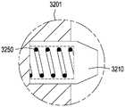
所述带端口套管接箍还包括一对移位卡爪凹槽。所述移位卡爪凹槽(其可以是单个连续凹槽)沿着所述内套筒的内径定位、接近所述管状本体的所述上端。所述移位卡爪凹槽被构造成接纳也沿着所述坐封工具的外径驻留的配合移位卡爪。所述移位卡爪又沿着所述坐封工具的所述外径位于所述对准块上方。The ported sleeve collar also includes a pair of shifting jaw grooves. The displacement dog groove, which may be a single continuous groove, is located along the inner diameter of the inner sleeve, proximate to the upper end of the tubular body. The displacement jaw groove is configured to receive a cooperating displacement jaw that also resides along the outer diameter of the setting tool. The displacing jaws are in turn positioned above the alignment block along the outer diameter of the setting tool.
所述带端口套管接箍任选地包括两个或更多个固定螺钉。所述固定螺钉驻留在外套筒中并且延伸到内套筒中。所述固定螺钉相对于所述外套筒固定内套筒的位置,直到被由所述坐封工具施加的旋转力剪切。The ported sleeve collar optionally includes two or more set screws. The set screw resides in the outer sleeve and extends into the inner sleeve. The set screw fixes the position of the inner sleeve relative to the outer sleeve until sheared by the rotational force applied by the setting tool.
在一个实施例中,所述带端口套管接箍还包括第一转环和第二转环。第一转环在所述上端处紧固到所述管状本体,而第二转环在所述下端处紧固到所述管状本体。每一转环被构造成螺纹地连接到生产套管的接头。In one embodiment, the ported sleeve collar further includes a first swivel and a second swivel. A first swivel is secured to the tubular body at the upper end and a second swivel is secured to the tubular body at the lower end. Each swivel is configured to threadably connect to a sub of the production casing.
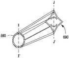
在一个方面中,所述外套筒包括扩大壁部分。所述扩大壁部分对管状本体形成偏心轮廓。令人感兴趣的是,所述扩大壁部分沿着管状本体的一侧向所述管状本体提供增加的重量,使得当沿着井筒的水平支腿放置所述带端口套管接箍时,相对的第一和第二转环准许所述管状本体旋转,使得所述扩大壁部分通过重力旋转到水平支腿的底部。所述带端口套管接箍被构造成使得在这种旋转时,所述东部入口和相对的西部入口水平地定位在所述井筒内。In one aspect, the outer sleeve includes an enlarged wall portion. The enlarged wall portion forms an eccentric profile to the tubular body. Interestingly, the enlarged wall portion provides increased weight to the tubular body along one side of the tubular body such that when the ported casing collar is placed along a horizontal leg of the wellbore, the relative The first and second swivels permit the tubular body to rotate such that the enlarged wall portion rotates by gravity to the bottom of the horizontal leg. The ported casing collar is configured such that upon such rotation, the eastern inlet and the opposing western inlet are positioned horizontally within the wellbore.
关于坐封工具,所述坐封工具可以限定具有内径和外径的管状本体。所述外径接纳所述移位卡爪和所述对准块。所述内径限定被构造成接纳喷射软管和所连接的喷射喷嘴的弯曲造斜器面。所述坐封工具进一步包括出口,其中当所述对准块放置在相应对准槽内时,所述出口与所述内套筒的指定内部入口对准。With regard to the setting tool, the setting tool may define a tubular body having an inner diameter and an outer diameter. The outer diameter receives the shifting jaw and the alignment block. The inner diameter defines a curved whipstock face configured to receive a spray hose and an attached spray nozzle. The setting tool further includes an outlet, wherein the outlet aligns with a designated interior inlet of the inner sleeve when the alignment block is placed within a corresponding alignment slot.
优选地,所述坐封设备被构造成在伸入管柱(run-in string)的端部处自由旋转。所述对准块的外部面从所述坐封工具的所述外径突出。每一对准块包括使个别块段向外偏置的多个弹簧。当所述坐封工具降低到所述带端口套管接箍的所述内径中时,包括相应对准块的所述块段被构造成沿着所述有斜面凸肩骑跨,从而使所述坐封工具旋转,并且使所述对准块着落在所述对准槽中。Preferably, the setting device is configured to rotate freely at the end of a run-in string. An outer face of the alignment block protrudes from the outer diameter of the setting tool. Each alignment block includes a plurality of springs that bias the individual block segments outward. When the setting tool is lowered into the inner diameter of the ported casing collar, the block segments, including corresponding alignment blocks, are configured to ride along the beveled shoulder so that the The setting tool rotates and lands the alignment block in the alignment groove.
本文中还提供一种进入地下地层中的岩石基质的方法。所述方法首先包括提供带端口套管接箍。在其各种实施例中,所述带端口套管接箍根据上文描述的套管接箍。Also provided herein is a method of accessing a rock matrix in a subterranean formation. The method first includes providing a ported casing collar. In its various embodiments, said ported casing collar is according to the casing collar described above.
所述方法包括:将所述管状本体的所述上端螺纹地紧固到生产套管的第一接头;以及将所述管状本体的所述下端螺纹地紧固到生产套管的第二接头。所述方法进一步包括使生产套管的所述接头和所述带端口套管接箍伸展到井筒的水平部分中。The method includes: threadably securing the upper end of the tubular body to a first sub of production casing; and threadably securing the lower end of the tubular body to a second sub of production casing. The method further includes extending the joint of production casing and the ported casing collar into a horizontal portion of the wellbore.
所述方法另外包括使坐封工具伸展到所述井筒中。如上所述,所述坐封工具可以是造斜器。所述方法然后包括操纵所述坐封工具以沿着控制槽移动所述扭矩销,从而使所述内套筒的内部入口与所述外套筒的所述“东部”和“西部”入口选择性地对准。The method additionally includes extending a setting tool into the wellbore. As mentioned above, the setting tool may be a whipstock. The method then includes manipulating the setting tool to move the torque pin along a control slot so that the inner inlet of the inner sleeve is selected with the "eastern" and "western" inlets of the outer sleeve Sexually aligned.
在所述方法的一个方面中,当所述带端口套管接箍伸展到所述井筒中时,内套筒处于其第一位置中。在此位置中,所述内套筒的所述内部入口不与所述外套筒的所述“东部”和“西部”入口对准。In one aspect of the method, the inner sleeve is in its first position when the ported casing collar is extended into the wellbore. In this position, the inner inlets of the inner sleeve are not aligned with the "eastern" and "western" inlets of the outer sleeve.
操纵所述坐封工具包括:Manipulating the setting tool includes:
•将所述内套筒放置在第二位置中,其中所述内套筒的所述内部入口中的一者与所述外套筒的所述“东部”入口对准,• placing the inner sleeve in a second position with one of the inner inlets of the inner sleeve aligned with the "eastern" inlet of the outer sleeve,
•将所述内套筒放置在第三位置中,其中所述内套筒的所述内部入口中的一者与所述外套筒的所述“西部”入口对准,以及• placing the inner sleeve in a third position with one of the inner inlets of the inner sleeve aligned with the "western" inlet of the outer sleeve, and
•将所述内套筒放置在第四位置中,其中所述内套筒的内部入口共同与所述外套筒的相应“东部”和“西部”入口对准。• Place the inner sleeve in the fourth position, with the inner inlets of the inner sleeve co-aligned with the corresponding "Eastern" and "Western" inlets of the outer sleeve.
在一个方面中,所述带端口套管接箍再次包括第一转环和第二转环。第一转环在所述上端处紧固到所述管状本体,而第二转环在所述下端处紧固到所述管状本体。所述管状本体通过所述第一转环螺纹地连接到生产套管的所述第一接头,并且所述管状本体通过所述第二转环螺纹地连接到生产套管的所述第二接头。In one aspect, the ported casing collar again includes a first swivel and a second swivel. A first swivel is secured to the tubular body at the upper end and a second swivel is secured to the tubular body at the lower end. The tubular body is threadably connected to the first joint of production casing by the first swivel, and the tubular body is threadably connected to the second joint of production casing by the second swivel .
所述方法可以然后包括沿工作管柱向下并且通过所述坐封工具泵送液压流体以便锁定所述第一和第二转环以防旋转,从而也锁定螺纹地连接的外套筒。The method may then include pumping hydraulic fluid down the workstring and through the setting tool to lock the first and second swivels against rotation, thereby also locking the threadably connected outer sleeve.
关于坐封工具,所述坐封工具可以限定具有内径和外径的管状本体。所述外径接纳所述移位卡爪和所述对准块。所述内径限定被构造成接纳喷射软管和所连接的喷射喷嘴的弯曲造斜器面。所述坐封工具进一步包括出口,其中当所述对准块放置在相应对准槽内时,所述出口与所述内套筒的指定内部入口对准。With regard to the setting tool, the setting tool may define a tubular body having an inner diameter and an outer diameter. The outer diameter receives the shifting jaw and the alignment block. The inner diameter defines a curved whipstock face configured to receive a spray hose and an attached spray nozzle. The setting tool further includes an outlet, wherein the outlet aligns with a designated interior inlet of the inner sleeve when the alignment block is placed within a corresponding alignment slot.
所述坐封工具的所述内径包括用于接纳所述喷射软管和所连接喷射喷嘴的弯折隧道。所述弯折隧道的中心线沿着所述坐封工具的纵向轴线的中心线。所述造斜器面驻留在所述弯折隧道的下端处并且横跨所述坐封工具的整个外径。所述弯折隧道被构造成接纳所述喷射软管和所连接的喷射喷嘴,使得所述喷射软管以半径“R”跨越所述造斜器面行进到所述出口。The inner diameter of the setting tool includes a bend tunnel for receiving the spray hose and attached spray nozzle. The centerline of the bent tunnel is along the centerline of the longitudinal axis of the setting tool. The whipstock face resides at the lower end of the meander tunnel and spans the entire outer diameter of the setting tool. The bend tunnel is configured to receive the spray hose and attached spray nozzle such that the spray hose travels across the whipstock face to the outlet at a radius "R".
在所述方法中,操纵所述坐封工具以移动所述扭矩销可以包括:In the method, manipulating the setting tool to move the torque pin may include:
• 向所述坐封工具施加向下力并且使所述坐封工具的所述移位卡爪着落到所述内套筒的所述移位卡爪凹槽中,所述内套筒处于其第一位置中;• Apply downward force to the setting tool and land the displacement jaws of the setting tool into the displacement jaw grooves of the inner sleeve in its in the first position;
• 顺时针方向旋转所述造斜器,从而通过所述对准块向所述内套筒施加扭矩直到固定螺钉被剪切,并且从而将所述扭矩销放置在所述控制槽的第一轴向部分中;以及• Rotate the whipstock clockwise to apply torque to the inner sleeve through the alignment block until the set screw is sheared and thereby place the torque pin on the first axis of the control slot into the section; and
• 向所述坐封工具和所连接内套筒施加向上力以沿着所述控制槽的所述第一轴向部分升高所述扭矩销,后跟坐封工具的逆时针方向旋转,从而沿着控制槽移动扭矩销并且将所述内套筒放置在其第二位置中。• Apply upward force to the setting tool and attached inner sleeve to raise the torque pin along the first axial portion of the control slot, followed by counterclockwise rotation of the setting tool, thereby Move the torque pin against the control slot and place the inner sleeve in its second position.
操纵所述坐封工具以移动所述扭矩销可以进一步包括:Manipulating the setting tool to move the torque pin may further comprise:
• 再次顺时针方向旋转所述造斜器,从而通过所述对准块向所述内套筒施加扭矩并且从而将所述扭矩销放置在所述控制槽的第二轴向部分中;• Rotate the whipstock clockwise again, applying torque to the inner sleeve through the alignment block and thereby placing the torque pin in the second axial portion of the control slot;
• 再次向所述坐封工具和所连接的内套筒施加向上力,后跟所述坐封工具的另一顺时针方向旋转,从而沿着控制槽移动扭矩销并且将所述内套筒放置在其第三位置中;• Apply upward force again to the setting tool and attached inner sleeve, followed by another clockwise rotation of the setting tool, moving the torque pin along the control slot and placing the inner sleeve in in its third position;
• 逆时针方向旋转所述造斜器,从而通过所述对准块向所述内套筒施加扭矩并且从而将所述扭矩销放置回所述控制槽的所述第二轴向部分中;• Rotate the whipstock counterclockwise, thereby applying torque to the inner sleeve through the alignment block and thereby placing the torque pin back in the second axial portion of the control slot;
• 再次向所述坐封工具和所连接的内套筒施加向上力以沿着所述控制槽的所述第二轴向部分升高所述扭矩销,后跟所述坐封工具的另一顺时针方向旋转,从而沿着控制槽移动扭矩销并且将所述内套筒放置在其第四位置中;• Apply upward force again to the setting tool and attached inner sleeve to raise the torque pin along the second axial portion of the control slot, followed by another sequential motion of the setting tool Rotate clockwise, thereby moving the torque pin along the control slot and placing the inner sleeve in its fourth position;
• 逆时针方向旋转所述造斜器,从而通过所述对准块向所述内套筒施加扭矩并且从而将所述扭矩销放置在所述控制槽的第三轴向部分中;以及• rotating the whipstock counterclockwise, thereby applying torque to the inner sleeve through the alignment block and thereby placing the torque pin in the third axial portion of the control slot; and
• 再次向所述坐封工具和所连接的内套筒施加向上力以沿着所述控制槽的所述第三轴向部分升高所述扭矩销,后跟所述坐封工具的逆时针方向旋转,从而沿着控制槽移动扭矩销并且将所述内套筒放置在其第五位置中。• Apply upward force again to the setting tool and attached inner sleeve to raise the torque pin along the third axial portion of the control slot, followed by counterclockwise direction of the setting tool Rotation moves the torque pin along the control slot and places the inner sleeve in its fifth position.
使用带端口套管接箍,可以进行地层增产操作,所述操作涉及一个或多个小支渠钻孔从子井筒的形成。支渠钻孔(lateral borehole)被液压地挖掘穿过对准入口,并且进入到存在于周围岩石基质内的产油气带中。产油气带已经被识别为拥有或至少潜在地拥有烃类流体或富含有机物的岩石。Using the ported casing collar, formation stimulation operations involving the formation of one or more small lateral boreholes from the sub-wellbore may be performed. Lateral boreholes are hydraulically excavated through the aligned inlets and into the pay zone that exists within the surrounding rock matrix. Pay zones have been identified as hosting or at least potentially hosting hydrocarbon fluids or organic-rich rocks.
带端口套管接箍可以被布置成使得:Ported casing collars may be arranged so that:
在所述扩大壁部分通过重力旋转到真正竖直底部处或其附近之后,所述带端口套管接箍被构造成使得所述东部入口已经定位成低于或高于真正水平面,并且相对的西部入口已经定位成低于或高于真正水平面,使得从所述东部入口的中心通过所述西部入口的中心绘制的矢量包括平行于或接近平行于主产油气带的层理平面的直线。After the enlarged wall section has been rotated by gravity to be at or near a true vertical bottom, the ported casing collar is configured such that the eastern inlet has been positioned below or above true water level and the opposite The western inlet has been positioned below or above true water level such that a vector drawn from the center of the eastern inlet through the center of the western inlet includes straight lines that are parallel or nearly parallel to the bedding planes of the main pay zone.
替代性地,带端口套管接箍可以被布置成使得:Alternatively, ported casing collars may be arranged such that:
在所述扩大壁部分通过重力旋转到真正竖直底部处或附近之后,所述带端口套管接箍被构造成使得所述东部入口已经定位在真正竖直面的顶部处或附近,并且相对的西部入口已经定位在真正竖直面的底部处或附近,使得从所述东部入口的中心通过所述西部入口的中心绘制的矢量将包括在真正竖直面处或附近的直线。After the enlarged wall section has been rotated by gravity to be at or near the true vertical bottom, the ported casing collar is configured such that the eastern inlet has been positioned at or near the top of the true vertical face and relatively The western inlet of has been positioned at or near the bottom of the true vertical plane such that a vector drawn from the center of the eastern inlet through the center of the western inlet will include a line at or near the true vertical plane.
附图说明Description of drawings
为可以更好地理解本发明的方式,在此附加某些图解、图表和/或流程图。然而,应注意的是,附图仅示出本发明的选定实施例,并且因此不视为对范围的限制,因为本发明可以容许其他等效实施例和应用。In order that the manner in which the present invention may be better understood, certain illustrations, diagrams and/or flow diagrams are attached hereto. It is to be noted, however, that the appended drawings illustrate only selected embodiments of the invention and are therefore not to be considered limiting of scope, for the invention may admit to other equally effective embodiments and applications.
图1A是说明性水平井筒的横截面视图。半裂缝平面沿着井筒的水平支腿以三维视图示出以示出相对于地下地层的裂缝级和裂缝取向。Figure 1A is a cross-sectional view of an illustrative horizontal wellbore. Half-fracture planes are shown in three-dimensional views along the horizontal legs of the wellbore to illustrate fracture levels and fracture orientations relative to the subterranean formation.
图1B是图1A的井筒的水平部分的放大图。常规射孔被超深射孔(“UDP”)或随后被压裂以形成裂缝平面的微型支渠钻孔替代。Figure IB is an enlarged view of a horizontal portion of the wellbore of Figure IA. Conventional perforating is replaced by ultra-deep perforating ("UDP") or micro-branch drilling that is subsequently fractured to create a fracture plane.
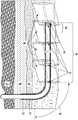
图2是在一个实施例中本发明的井下水力喷射组件的纵向横截面视图。所述组件示出为在生产套管的水平区段内。所述喷射组件具有外部系统和内部系统。Figure 2 is a longitudinal cross-sectional view of the downhole hydrojeting assembly of the present invention in one embodiment. The assembly is shown within a horizontal section of the production casing. The jetting assembly has an external system and an internal system.
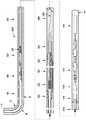
图3A是图2的水力喷射组件的内部系统的纵向横截面视图。内部系统从在其近侧端部处的上游电池组端盖(与外部系统的衔接站配合)延伸到在其远侧端部处的具有喷射喷嘴的细长软管。3A is a longitudinal cross-sectional view of the internal systems of the hydrojet assembly of FIG. 2 . The inner system extends from an upstream battery pack end cap at its proximal end (which mates with the docking station of the outer system) to an elongated hose with a spray nozzle at its distal end.
图3B是图3A的喷射软管的终端的放大横截面视图,其示出内部系统的喷嘴。喷射软管的弯折半径“R”示出在图3B的外部系统的造斜器的剖开截面内。3B is an enlarged cross-sectional view of the terminal end of the spray hose of FIG. 3A showing the nozzle of the internal system. The bend radius "R" of the injection hose is shown in cut-away section of the whipstock of the external system of FIG. 3B.
图4是在一个实施例中图2的井下水力喷射组件的外部系统的纵向横截面视图。外部系统驻留在图2的井筒的水平支腿的生产套管内。4 is a longitudinal cross-sectional view of the external system of the downhole hydrojetting assembly of FIG. 2 in one embodiment. The external system resides within the production casing of the horizontal leg of the wellbore of FIG. 2 .
图4A是将图4的外部系统输送进和输送出井筒的成束连续油管输送介质的一部分的放大纵向横截面视图。4A is an enlarged longitudinal cross-sectional view of a portion of a bundle of coiled tubing transport media transporting the external system of FIG. 4 into and out of a wellbore.
图4A-1a是图4A的连续油管输送介质的轴向横截面视图。在此实施例中,内部连续油管与电线和数据电缆一起在保护性外层内同心地“成束”。4A-1a is an axial cross-sectional view of the coiled tubing transport medium of FIG. 4A. In this embodiment, the inner coiled tubing is "bundled" concentrically within a protective outer layer along with the electrical and data cables.
图4A-2是图4A-1a的但是在不同实施例中的连续油管输送介质的另一轴向横截面视图。此处,内部连续油管在保护性外层内偏心地“成束”以提供对电线和数据电缆的更均匀间隔的保护。4A-2 is another axial cross-sectional view of the coiled tubing transport medium of FIG. 4A-1a but in a different embodiment. Here, the inner coiled tubing is "bunched" off-center within the protective outer layer to provide more evenly spaced protection for the wires and data cables.
图4B是跨接连接的纵向横截面视图,其是图4的外部系统的最上部构件。跨接区段被构造成将图4A的连续油管输送介质联接到主控制阀。4B is a longitudinal cross-sectional view of a jumper connection, which is the uppermost member of the external system of FIG. 4 . The crossover section is configured to couple the coiled tubing transport medium of FIG. 4A to the main control valve.
图4B-1a是在横截面E-E'与F-F'之间看到的图4B的跨接连接的放大透视图。此视图突出显示布线室的横截面形状从圆形到椭圆形的大致过渡。Figure 4B-1a is an enlarged perspective view of the jumper connection of Figure 4B seen between cross-sections EE' and FF'. This view highlights the approximate transition of the wiring compartment's cross-sectional shape from circular to oval.
图4C是图4的外部系统的主控制阀的纵向横截面视图。4C is a longitudinal cross-sectional view of the main control valve of the external system of FIG. 4 .
图4C-1a是主控制阀的跨越图4C的线G- G'截取的横截面视图。Figure 4C-1a is a cross-sectional view of the main control valve taken across line GG' of Figure 4C.
图4C-1b是从图4C-1a分解示出的主控制阀的密封通路盖的透视图。Fig. 4C-1b is a perspective view of the sealing passage cover of the main control valve shown exploded from Fig. 4C-1a.
图4D是图4的外部系统的选定部分的纵向横截面视图。可见喷射软管封隔区段,以及从喷射软管托架区段的先前圆形本体(I-I')到喷射软管封隔区段的星形本体(J-J')的外部本体过渡。4D is a longitudinal cross-sectional view of selected portions of the external system of FIG. 4 . The spray hose containment section is visible, and the outer body from the previous circular body (I-I') of the spray hose bracket section to the star shaped body (J-J') of the spray hose containment section transition.
图4D-1a是图4D的线I-I’与J-J’之间的过渡的放大透视图。Figure 4D-1a is an enlarged perspective view of the transition between lines I-I' and J-J' of Figure 4D.
图4D-2示出喷射软管封隔区段的一部分的放大图。封隔区段的内部密封件与驻留在其中的喷射软管的外周向部分一致。邻近封隔区段示意性地示出压力调节器阀。Figure 4D-2 shows an enlarged view of a portion of a spray hose containment section. The inner seal of the containment section conforms to the outer circumferential portion of the spray hose residing therein. A pressure regulator valve is shown schematically adjacent to the containment section.
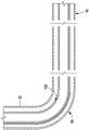
图4E是图4的外部系统的造斜器构件的横截面视图,但是竖直而非水平地示出。内部系统的喷射软管示出为跨越造斜器弯折,并且延伸穿过生产套管中的窗。示出内部系统的喷射喷嘴示出为附着到喷射软管的远侧端部。Figure 4E is a cross-sectional view of a whipstock member of the external system of Figure 4, but shown vertically rather than horizontally. The injection hose of the internal system is shown bent across the whipstock and extending through a window in the production casing. The spray nozzle showing the internal system is shown attached to the distal end of the spray hose.
图4E-1a是造斜器构件的轴向横截面视图,其中顺序轴向喷射软管横截面的透视图绘示其从跨越图4E的线O-O'截取的造斜器构件的中心到喷射软管(当其接近线P-P'时)的弯折半径的起始点的下游路径。4E-1a is an axial cross-sectional view of a whipstock member with a perspective view of a sequential axial injection hose cross-section depicted from the center of the whipstock member taken across line OO' of FIG. 4E to The path downstream of the starting point of the bend radius of the spray hose (as it approaches line PP').
图4E-1b绘示跨越图4E的线P-P'截取的造斜器构件的轴向横截面视图。Figure 4E-lb depicts an axial cross-sectional view of the whipstock member taken across line PP' of Figure 4E.
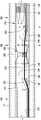
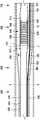
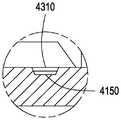
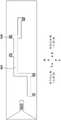
图4MW是被设计成可配合地接纳在带端口套管接箍内的经改进造斜器的纵向横截面视图。经改进造斜器的平移和旋转移动致动带端口套管接箍的内套筒的移动,从而提供预先形成的套管出口。Figure 4MW is a longitudinal cross-sectional view of an improved whipstock designed to be matably received within a ported casing collar. Translational and rotational movement of the improved whipstock actuates movement of the inner sleeve of the ported casing collar to provide a pre-formed casing exit.
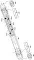
图4MW.1是经改进造斜器的分解图,其中喷射软管出口与套管接箍的内套筒和外套筒的入口对准。Figure 4MW.1 is an exploded view of a modified whipstock with jet hose outlets aligned with the inlets of the inner and outer sleeves of the casing collar.
图4MW.2是图4MW.1的造斜器的放大图。此处,造斜器围绕纵向通道旋转90°,从而露出一对相对“移位卡爪”。Figure 4MW.2 is an enlarged view of the whipstock of Figure 4MW.1. Here, the whipstock is rotated 90° about the longitudinal channel, thereby exposing a pair of opposing "displacement dogs".
图4MW.2.SD是两个弹簧加载移位卡爪中的一者的分解横截面视图。Figure 4MW.2.SD is an exploded cross-sectional view of one of the two spring-loaded displacement jaws.
图4MW.2.AB是图4MW的弹簧加载对准块中的一者的一部分的分解横截面视图。Figure 4MW.2.AB is an exploded cross-sectional view of a portion of one of the spring-loaded alignment blocks of Figure 4MW.
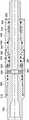
图4PCC.1是图4MW的带端口套管接箍的纵向横截面视图。Figure 4PCC.1 is a longitudinal cross-sectional view of the ported casing collar of Figure 4MW.
图4PCC.1.SDG是驻留在图4PCC.1的带端口套管接箍中的移位卡爪凹槽的分解纵向横截面视图。所述移位卡爪凹槽被定尺寸成接纳经改进造斜器的移位卡爪。Figure 4PCC.1.SDG is an exploded longitudinal cross-sectional view of the shifting jaw groove residing in the ported casing collar of Figure 4PCC.1. The shifting dog grooves are dimensioned to receive the shifting dogs of the improved whipstock.
图4PCC.1.CLD是图4PCC.1的带端口套管接箍的夹头闩锁卡爪的分解横截面视图。Figure 4PCC.1.CLD is an exploded cross-sectional view of the collet latch jaw of the ported casing collar of Figure 4PCC.1.
图4PCC.1.CSP是带端口套管接箍的内套筒的控制槽图案的二维“展开”视图,其示出五个可能槽位置中的每一者。Figure 4PCC.1.CSP is a two-dimensional "unfolded" view of the control slot pattern of the inner sleeve with port casing collar showing each of the five possible slot locations.
图4PCC.2是操作系列,其示出当内套筒平移和旋转到其五个可能位置中的每一者时,外套筒的两个静止入口中的每一者对比内套筒的三个入口中的每一者的相对位置。Figure 4PCC.2 is a series of operations showing each of the two stationary inlets of the outer sleeve versus the three of the inner sleeve as the inner sleeve translates and rotates to each of its five possible positions. The relative position of each of the entrances.
图4PCC.3d.1-图4PCC.3d.5是图4PCC.1的带端口套管接箍的一系列透视图。图4PCC.3d.1-图4PCC.3d.5示出当按照图4PCC.2的控制槽位置沿着生产套管管柱放置时带端口套管接箍的位置。Figures 4PCC.3d.1 - 4PCC.3d.5 are a series of perspective views of the ported casing collar of Figure 4PCC.1. Figures 4PCC.3d.1-4PCC.3d.5 show the position of the ported casing collar when the control groove position according to Figure 4PCC.2 is placed along the string of production casing.
图4PCC.3d.1示出处于其中内套筒入口和外套筒入口不对准的位置中的带端口套管接箍。这是“闭合”位置。Figure 4PCC.3d.1 shows the ported casing collar in a position where the inner and outer sleeve inlets are not aligned. This is the "closed" position.
图4PCC.3d.2示出某些内套筒入口与某些外套筒入口的对准,其中“东部”端口是打开的。Figure 4PCC.3d.2 shows the alignment of certain inner sleeve inlets with certain outer sleeve inlets where the "Eastern" port is open.
图4PCC.3d.3示出某些内套筒入口与某些外套筒入口的对准,其中“西部”端口是打开的。Figure 4PCC.3d.3 shows the alignment of certain inner sleeve inlets with certain outer sleeve inlets where the "west" port is open.
图4PCC.3d.4示出某些内套筒入口与某些外套筒入口的对准,其中“东部”和“西部”端口两者都是打开的。Figure 4PCC.3d.4 shows the alignment of certain inner sleeve inlets with certain outer sleeve inlets, where both the "east" and "west" ports are open.
图4PCC.3d.5再次示出未对准的内套筒入口和外套筒入口。这是另一闭合位置。Figure 4PCC.3d.5 again shows misaligned inner and outer sleeve inlets. This is another closed position.
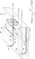
图4HLS是可以放置在图4PCC.3d.1-图4PCC.3d.5的带端口套管接箍的每一端处的液压锁定转环的纵向横截面视图。Figure 4HLS is a longitudinal cross-sectional view of a hydraulic locking swivel that may be placed at each end of the ported casing collar of Figures 4PCC.3d.1-4PCC.3d.5.
图5A是产烃油田的透视图。在此视图中,相邻于母井筒完井子井筒。在子的完井期间泵送压裂级“n”时,母井筒周围的产油气带中的消耗吸引压裂冲击。Figure 5A is a perspective view of a hydrocarbon producing oil field. In this view, the child wellbore is completed adjacent to the parent wellbore. When the frac stage "n" is pumped during the child's completion, the depletion in the pay zone around the parent wellbore attracts the frac shock.
图5B是图5A的产烃油田的另一透视图。从子井筒示出额外压裂级。Figure 5B is another perspective view of the hydrocarbon producing field of Figure 5A. Additional fracturing stages are shown from the sub-wellbore.
具体实施方式Detailed ways
定义definition
如本文中所使用,术语“烃类”是指主要、但不排他地包括元素氢和碳的有机化合物。含烃材料的实例包括可以用作燃料或提质成燃料的任何形式的天然气、石油、煤炭和沥青。As used herein, the term "hydrocarbon" refers to an organic compound comprising primarily, but not exclusively, the elements hydrogen and carbon. Examples of hydrocarbonaceous materials include natural gas, petroleum, coal, and bitumen in any form that can be used as fuel or upgraded to fuel.
如本文中所使用,术语“流体”是指气体、液体以及气体和液体的组合,以及气体和固体的组合以及液体和固体的组合。As used herein, the term "fluid" refers to gases, liquids, and combinations of gases and liquids, as well as combinations of gases and solids and combinations of liquids and solids.
如本文中所使用,术语“烃类流体”是指在地层条件下、处理条件下或环境条件下为气体或液体的烃类或烃类的混合物。实例包括石油、天然气、凝析油、煤层气、页岩油、页岩气和呈气态或液态的其他烃类。As used herein, the term "hydrocarbon fluid" refers to a hydrocarbon or mixture of hydrocarbons that is a gas or a liquid at formation conditions, process conditions, or ambient conditions. Examples include oil, natural gas, condensate, coal bed methane, shale oil, shale gas, and other hydrocarbons in gaseous or liquid form.
如本文中所使用,术语“地下”是指存在于地球的表面下方的地质地层。As used herein, the term "subterranean" refers to geological formations that exist below the Earth's surface.
术语“地下层段”是指其中地层流体可以驻留的地层或地层的一部分。流体可以例如是烃类液体、烃类气体、水性流体或其组合。The term "subterranean interval" refers to a formation or a portion of a formation in which formation fluids may reside. The fluid may for example be a hydrocarbon liquid, a hydrocarbon gas, an aqueous fluid or a combination thereof.
术语“气带”或“感兴趣气带”是指包含烃类的地层的一部分。有时,可以使用术语“目标气带”、“产油气带”、“储集层”、或“层段”。The term "gas zone" or "gas zone of interest" refers to a portion of a formation that contains hydrocarbons. At times, the terms "target gas zone", "pay zone", "reservoir", or "interval" may be used.
如本文中所使用,术语“钻孔”是指地表下岩石中的挖掘出的空隙空间,其通常具有圆形横截面并且由挖掘机构产生;例如,钻探或喷射。钻孔几乎可以具有任何纵向方位角或取向,并且长度可以长达数百(喷射)或更通常数千或数万英尺(钻探)。As used herein, the term "borehole" refers to an excavated void space in subsurface rock that is generally of circular cross-section and is created by an excavating mechanism; eg, drilling or jetting. Boreholes can have virtually any longitudinal azimuth or orientation, and can be hundreds of (jetting) or more typically thousands or tens of thousands of feet (drilling) in length.
如本文中所使用的,术语“井筒”是指通过钻探挖掘并且随后沿着其大部分长度(如果不是其整个长度)套装(通常用钢套管)的钻孔。通常需要套管的至少3个或更多个同心管柱来形成井筒,用于烃类的生产。每一套管通常沿着其长度的大部分固结在钻孔内,其中较大直径、较浅管柱的固结需要到地表的循环。如本文中所使用,术语“井”可以与术语“井筒”互换使用。As used herein, the term "wellbore" refers to a borehole excavated by drilling and then cased (usually with steel casing) along most, if not all, of its length. Typically at least 3 or more concentric strings of casing are required to form a wellbore for the production of hydrocarbons. Each casing is typically consolidated within the borehole along most of its length, with consolidation of larger diameter, shallower strings requiring circulation to the surface. As used herein, the term "well" may be used interchangeably with the term "wellbore".
术语“喷射流体”是指出于从现有井筒侵蚀性地钻取支渠钻孔的目的泵送通过喷射软管和喷嘴组件的任何流体。喷射流体可以包含或可以不包含磨料。The term "jet fluid" refers to any fluid that is pumped through the jet hose and nozzle assembly for the purpose of erosively drilling a lateral borehole from an existing wellbore. The jetting fluid may or may not contain abrasives.
术语“磨料”或“研磨剂”是指如下小固体颗粒:其与喷射流体混合或悬浮在喷射流体中以通过经由研磨剂的固体冲击力向目标添加目标面的破坏来增强(喷射)液体对目标的侵蚀退化。本文中通常提及的目标是:(1) 产油气带;和/或(2)生产套管与产油气带之间的水泥护层;和/或(3)所期望套管出口的点处的生产套管的壁。The terms "abrasive" or "abrasive" refer to small solid particles that are mixed with or suspended in the jetting fluid to enhance (jet) the liquid's impact on the surface by adding damage to the target surface through the solid impact force of the abrasive to the target. Erosion and degradation of the target. The targets generally referred to herein are: (1) the pay zone; and/or (2) the cement sheath between the production casing and the pay zone; and/or (3) the point at which casing exit is desired The wall of the production casing.
术语“管状”或“管状构件”是指任何管,诸如套管的接头、衬管的一部分、油管的接头、短节或连续油管。The term "tubular" or "tubular member" refers to any pipe, such as a joint of casing, a portion of a liner, a joint of tubing, a pup joint, or coiled tubing.
术语“支渠钻孔”或“微型支渠”或“超深射孔”(“UDP”)是指地下地层中、通常在子井筒中在离开生产套管及其周围水泥护层时所产生的钻孔,其中所述钻孔形成在产油气带中。出于本文中的目的,UDP因侵蚀性地钻孔穿过产油气带的水力喷射力而形成,其中高压喷射流体被指引通过喷射软管,并且指引出附着到喷射软管的终端的喷射喷嘴。The term "branch drilling" or "microbranch" or "ultra-deep perforation" ("UDP") refers to the drilling of holes in a subsurface formation, usually in a subwellbore, upon leaving the production casing and its surrounding cement covering. borehole, wherein the borehole is formed in a pay zone. For the purposes of this article, the UDP is formed by the force of hydrojet drilling erosively through the pay zone, where high-pressure jet fluid is directed through the jet hose and out to the jet nozzle attached to the end of the jet hose .
术语“可转向”或“可引导”当应用于水力喷射组件时是指操作者可以在喷射组件在操作时针对其指引和控制其地理空间取向的喷射组件的一部分(通常,喷射喷嘴和/或喷射软管的紧邻喷嘴的部分)。此在侵蚀性挖掘的过程期间指引并且随后重新定向喷射组件的取向的能力可以视期望产生具有一维、二维或三维的定向分量的UDP。The terms "steerable" or "guidable" when applied to a hydrojet assembly refer to the portion of the spray assembly (typically, the spray nozzle and/or the portion of the spray hose immediately adjacent to the nozzle). This ability to direct and then reorient the orientation of the jetting assembly during the course of erosive excavation can produce a UDP with a one-, two-, or three-dimensional directional component, as desired.
术语“射孔集群”是指一组常规射孔,和/或在共用井筒中通常彼此接近的滑动套筒端口。给定射孔集群通常借助共同压裂“级”来水力压裂增产,通常,目的是在产油气带内形成单个连续增产储集层体积(“SRV”)。在本公开内容中,可以使用“集群”来指代针对压裂级形成在单个套管出口位置处的两个或更多个支渠钻孔。The term "perforation cluster" refers to a group of conventional perforations, and/or sliding sleeve ports that are generally close to each other in a common wellbore. A given perforation cluster is typically stimulated hydraulically by means of a common fracture "stage," usually with the goal of forming a single continuous stimulated reservoir volume ("SRV") within the pay zone. In this disclosure, "cluster" may be used to refer to two or more branch boreholes formed at a single casing exit location for a fracturing stage.
术语“级”是指在完井或重新完井特定产油气带或产油气带的特定部分中应用的增产处理的分立部分。在套装水平子井筒的情况下,多达10个、20个、50个或更多个级可以应用于其相应射孔钻孔集群。通常,在泵送每一级之前,这需要某种形式的层位封隔。The term "stage" refers to discrete portions of stimulation treatments applied in completing or re-completing a particular pay zone or a specific portion of a pay zone. In the case of nested horizontal subwellbores, as many as 10, 20, 50 or more stages may be applied to their respective perforation borehole clusters. Typically, this requires some form of zonal isolation before each stage is pumped.
术语“轮廓”或“成轮廓”在应用于个别UDP或“集群”中的UDP分组时是指可转向地挖掘支渠钻孔以便最佳地接纳、指引和控制给定增产(通常,压裂)级的增产流体或流体和支撑剂。结果是经优化的增产储集层体积(“SRV”)。The terms "profiled" or "profiled" when applied to individual UDPs or groupings of UDPs in a "cluster" refer to steerable excavation of branch channel boreholes to best receive, direct and control a given stimulation (typically, fracturing) Level of stimulation fluid or fluid and proppant. The result is an optimized stimulated reservoir volume ("SRV").
对在泵送增产(诸如压裂)处理的级的过程期间获得的地球物理数据(诸如微地震、倾角仪和/或周围微地震数据)和/或压力数据(诸如从压力“计”获得)的术语“实时”或“实时分析”意味着所述数据分析的结果可以应用于:(1) 改变增产处理的剩余部分(尚未泵送)的泵速、处理压力、流体流变性和支撑剂浓度,以便优化从其获得的益处;以及,(2)在后续“集群”内优化射孔的放置或使UDP的轨迹成轮廓以优化从后续增产级获得的SRV。Geophysical data (such as microseismic, inclinometer and/or ambient microseismic data) and/or pressure data (such as obtained from pressure "gages") obtained during the process of pumping stages of stimulation (such as fracturing) treatments The term "real-time" or "real-time analysis" means that the results of the data analysis described can be applied to: (1) change pump speed, process pressure, fluid rheology, and proppant concentration for the remainder of the stimulation treatment (not yet pumped) , in order to optimize the benefits derived therefrom; and, (2) optimize the placement of perforations within subsequent "clusters" or profile the trajectory of the UDP to optimize the SRV obtained from subsequent stimulation stages.
术语“母井筒”是指如下井筒:其已经完井并且正从产油气带生产储集层流体达一时间周期,从而在产油气带内形成压力消耗区。“母”井筒可以是竖直、水平或定向井。The term "parent wellbore" refers to a wellbore that has been completed and is producing reservoir fluids from a pay zone for a period of time, thereby creating a pressure depletion zone within the pay zone. A "parent" wellbore may be a vertical, horizontal or directional well.
术语“子井筒”是指在探边“母”井筒附近在共同产油气带中完井的井。The term "child wellbore" refers to a well completed in a co-produced zone adjacent to a delineated "parent" wellbore.
术语“压裂冲击”描述井间连通事件,其中“母”井受到新“子”井中水力压裂处理的泵送的影响。来自单个子井的压裂冲击可能冲击多于一个母井。The term "fracture shock" describes an interwell communication event in which a "parent" well is affected by the pumping of a hydraulic fracturing treatment in a new "child" well. A fracture shock from a single child well may strike more than one parent well.
术语“喷射软管”是指柔性流体导管,其能够在相对高压力(通常多达数千磅每平方英寸)下指引相对少量的流体。The term "spray hose" refers to a flexible fluid conduit capable of directing relatively small volumes of fluid at relatively high pressures (typically as much as several thousand pounds per square inch).
对具体实施例的描述Description of Specific Embodiments
本文中提供一种增产地下地层的方法。具体来说,提供一种诸如通过水力压裂来增产地层的方法,其中避免邻近井筒的所谓的“压裂冲击”,或者其中进入储集层的原本滞留部分。A method of stimulating a subterranean formation is provided herein. In particular, a method of stimulating a formation, such as by hydraulic fracturing, is provided wherein so-called "fracture shocks" adjacent to the wellbore, or wherein access to otherwise stagnant portions of the reservoir, are avoided.
所述方法采用如在标题为“Downhole Hydraulic Jetting Assembly(井下水力喷射组件)”的共同拥有的美国专利第9, 976,351号中公开的新颖井下水力喷射组件。此组件允许操作者将喷射软管伸展到井筒的水平区段中,并且然后使用液压力将喷射软管从管状喷射软管托架中“推出”。有益地,喷射软管从喷射软管托架中挤出并且抵靠造斜器的凹入面,于是喷射流体可以通过喷射软管和所连接的喷嘴注入。然后,可以从井筒延伸形成微型支渠钻孔。The method employs a novel downhole hydraulic jetting assembly as disclosed in commonly owned US Patent No. 9,976,351 entitled "Downhole Hydraulic Jetting Assembly." This assembly allows the operator to extend the jet hose into a horizontal section of the wellbore and then use hydraulic force to "push" the jet hose out of the tubular jet hose bracket. Advantageously, the spray hose is extruded from the spray hose bracket and abuts against the concave face of the whipstock, whereupon the spray fluid can be injected through the spray hose and the connected nozzle. Micro-branch boreholes can then be extended from the wellbore to form.
根据工业程序,在水平形成的井筒中进行水力压裂(或其他地层处理程序)。在此情况下,通过将压裂流体注入到支渠钻孔中来进行压裂。在本方法中,在压裂级期间监测探边井中的井筒压力。如果检测到指示即将发生的压裂冲击的压力,则中断压裂流体到支渠钻孔中的泵送。Hydraulic fracturing (or other formation treatment procedures) is performed in horizontally formed wellbores according to industry procedures. In this case, fracturing is performed by injecting fracturing fluid into branch channel boreholes. In the present method, wellbore pressure in a delineated well is monitored during the fracturing stage. If pressure is detected indicating an imminent fracturing shock, the pumping of fracturing fluid into the lateral borehole is interrupted.
在本方法的一个方面中,提供喷射组件的特别设计的造斜器。造斜器被设计成由新颖带端口套管接箍可配合地接纳,本文中也提供所述新颖带端口套管接箍。造斜器可以在地表处被操纵以选择性地对准套管接箍内的入口,从而形成喷射喷嘴和所连接的液压软管可以通过的套管窗或“套管出口”。然后,一个或多个钻孔可以通过对准的入口向外“喷射”到周围地下地层中。In one aspect of the method, a specially designed whipstock of the jetting assembly is provided. The whipstock is designed to be matably received by a novel ported casing collar, also provided herein. The whipstock can be manipulated at the surface to selectively align the inlet in the casing collar, thereby creating a casing window or "casing outlet" through which the injection nozzle and attached hydraulic hose can pass. One or more boreholes may then be "jetted" outward through the aligned inlets into the surrounding subterranean formation.
支渠钻孔实质上表示通过使用指引通过柔性高压喷射软管的液压力形成的超深射孔(“UDP”)。可以控制钻孔的轨迹和长度两者。使用井下组件,操作者能够使用单个软管和喷嘴来在单个行程中在水平井筒的支腿内喷射一系列支渠钻孔。Branch drilling essentially means ultra-deep perforation ("UDP") formed by using hydraulic pressure directed through a flexible high-pressure jet hose. Both the trajectory and the length of the borehole can be controlled. Using the downhole assembly, an operator can use a single hose and nozzle to jet a series of lateral boreholes in a single stroke within the legs of a horizontal wellbore.
图1A是水平井4的示意性绘示。井口5在地表1处位于井4上方。井4在到达产油气带3之前穿透通过一系列地下地层2a至2h。井4包括水平区段4c。水平区段4c绘示在“踵部”4b与“趾部”4d之间。FIG. 1A is a schematic representation of a
按上下对(up-and-down pair)示出生产套管12内的常规射孔15。射孔15绘示为具有后续水力裂缝半平面(或“压裂翼”)16。
图1B是图1A的井4的下部部分的放大图。此处,更清楚地看到踵部4b与趾部4d之间的水平区段4c。在此绘示中,本文中的本装置和方法的应用用若干对相对支渠钻孔15替代常规射孔(图1A中的15)。令人感兴趣的是,所述支渠钻孔包括随后产生的裂缝半平面16。在图1B的视图中,压裂翼16现在更好地限制在产油气带3内,同时从水平井筒4c出来远得多地到达产油气带3中。换句话说,预先形成的UDP 15增强气带内裂缝传播,从而形成经增强增产储集层体积或“SRV”。Figure IB is an enlarged view of the lower portion of the
图2提供在一个实施例中井下水力喷射组件50的纵向横截面视图。喷射组件50示出为驻留在生产套管12的管柱内。生产套管12可以具有例如4.5英寸外径(O.D.)(4.0英寸内径(I.D.))。生产套管12沿着井筒4的水平部分4c呈现。如结合图1A和图1B所述,水平部分4c限定踵部4b和趾部4d。Figure 2 provides a longitudinal cross-sectional view of a
喷射组件50通常包括内部系统1500和外部系统2000。喷射组件50被设计成在工作管柱(有时在本文中称为“输送介质”)的端部处伸展到井筒4中。优选地,工作管柱是连续油管的管柱,或者更优选地,具有电力线路(“电气-线圈(e-coil)”)100的连续油管的管柱。替代性地,可以使用在连续油管芯部周围并入导电布线和数据导电电缆(诸如光纤电缆)的“成束”产品。Jetting
优选地,将留下环状区域的连续油管100的外径维持在大于或等于3.5英寸(3.5''O.D.)外径压裂(油管)管柱的对流动开放的横截面积的大约4.0英寸(4.0'' I.D.)内径的套管12内。这是因为,在优选方法中(在喷射一个或多个、优选地两个相对微型支渠,或甚至特别成轮廓的小直径支渠钻孔的“集群”之后),压裂增产可以立即(在稍微在井下重新定位工具管柱之后)沿连续油管100加外部系统2000与井套管12之间的环隙发生。对于9.2#,3.5英寸外径油管(即,压裂管柱等效物),内径为2.992英寸,并且对流动开放的横截面积为7.0309平方英寸。从该相同7.0309平方英寸等效物反算产生2.655英寸的可用于连续油管输送介质100和外部系统2000(具有大致圆形横截面)的最大外径。当然,可以使用任一者的较小外径,只要此容纳喷射软管1595。Preferably, the outside diameter of the coiled
在图2的视图中,组件50处于操作位置中,其中喷射软管1595伸展穿过造斜器1000,并且喷射喷嘴1600穿过生产套管12的第一窗“W”。喷射软管1595将优选地具有芯部,所述芯部是流体不可渗透的,并且对流动的流体具有低摩擦阻力。合适芯部材料包括PTFE(或“Teflon®”)。喷射软管1595还将在芯部周围具有一个或多个加强层,诸如螺旋形或编织钢丝或编织凯夫拉尔纤维(kevlar)。最后,在加强层周围放置盖或罩。In the view of FIG. 2 , the
喷嘴1600可以是任何已知喷射喷嘴,包括在‘351专利中描述的那些喷射喷嘴,用于喷射穿过套管、水泥和岩石地层。然而,优选地,采用独特的电驱动的可旋转“扇形射流”喷射喷嘴作为外部系统的一部分。喷嘴可以模仿常规液压射孔器的液压系统,从而防止需要借助铣削工具单独运行以形成套管出口。喷嘴任选地在本体周围包括向后推进射流以在支渠钻孔形成期间增强向前推力和钻孔清洁,并且在拉出期间提供清除和钻孔膨胀。
作为替代特征,造斜器1000可以结合新颖套管接箍操作。在此情况下,造斜器1000使用延伸机构(下文论述)闩锁到接箍的内套筒中并操纵接箍的内套筒。以此方式,内套筒的入口可以选择性地与借助于施加到其加重腹部上的重力自我取向的外套筒的入口对准。然后,液压将外套筒锁定到此所期望取向中,从而使其相对于内套筒静止。然后,造斜器1000可以可配合地附接到内套筒,并且旋转地且平移地操纵内套筒,从而形成进入预先制作且预先取向的套管出口替代物的通道。As an alternative feature,
在图2中,使用连续油管100的管柱作为井下水力喷射组件的输送介质。喷射组件50包括内部系统(在图3A中示出在1500处)和外部系统(在图4中示出在2000处)。在伸入期间,内部系统1500主要驻留在外部系统2000内。In FIG. 2 , the
在300处指示的主控制阀在喷射组件50的近侧端部附近,恰好在其到输送介质连续油管100的连接的下游。主控制阀300将流体选择性地指引到:(1) 内部系统1500,并且具体指引到喷射软管1595;或者,(2) 与外部系统2000相关联的环隙。The main control valve, indicated at 300 , is near the proximal end of the
喷射软管托架400示出在图2中。喷射软管托架400是外部系统2000的一部分,并且在伸入和拉出期间紧密地保持喷射软管1595。微环隙驻留在喷射软管1595与喷射软管托架400之间。微环隙被定大小成防止喷射软管1595的屈曲。Spray
跨接区段示出在500、800和1200处。跨接区段500、800也是外部系统2000的一部分。另外,提供封隔区段600和任选的内部牵引器系统700。在‘351专利中描述了这些特征。Spanning sections are shown at 500 , 800 and 1200 . The spanning
任选的部件在喷射组件50的端部处并且在造斜器1000下方。这些部件可以包括常规牵引器1350和测井探测器(logging sonde)1400。Optional components are at the end of jetting
图3A是图2的水力喷射组件50的内部系统1500的纵向横截面视图。内部系统1500是可转向系统,其在操作时,能够在外部系统2000内移动并且从外部系统2000中延伸出来。内部系统1500主要包括以下部件:3A is a longitudinal cross-sectional view of
(1) 动力和地理控制部件;(1) Power and geographic control components;
(2) 喷射流体进口;(2) Jet fluid inlet;
(3) 喷射软管1595;以及(3)
(4) 喷射喷嘴1600。(4)
内部系统1500被设计成容纳在外部系统2000内,同时由连续油管100和所附接的外部系统2000输送进入和输送出子井筒4。内部系统1500从外部系统2000的延伸和回到外部系统2000中的缩回通过以下力的施加实现:(a) 液压力;(b)机械力;或(c) 液压力和机械力的组合。对包括水力喷射装置50的内部系统1500和外部系统2000的设计有益的是,喷射软管159的运输、展开或缩回从不需要喷射软管1595盘绕。具体来说,喷射软管1595从不经受小于生产套管12的内径的弯折半径,并且弯折半径仅在沿着外部系统2000的喷射软管造斜器构件1000的造斜器1050前进时递增。注意,喷射软管1595通常为能够承受高内部压力的1⁄4英寸至5/8英寸内径和高达大约1英寸外径的柔性管。The
在喷射期间,高压水力喷射流体的路径如下:During spraying, the path of the high pressure hydrojet fluid is as follows:
(1) 喷射流体从地表1处的高压泵沿连续油管输送介质100的内径向下排出,喷射流体在连续油管输送介质100的端部处进入外部系统2000;(1) The injection fluid is discharged from the high-pressure pump at the
(2) 喷射流体通过连续油管过渡连接200进入外部系统2000;(2) The injection fluid enters the
(3) 喷射流体通过喷射流体通路进入主控制阀300;(3) The injection fluid enters the
(4) 由于主控制阀300被定位成接收喷射流体(与液压流体相反),因此密封通路盖将被定位成密封液压流体通路,从而留下通过喷射流体通路的唯一可用流体路径;并且(4) Since the
(5) 由于密封喷射软管1595与喷射软管托架400之间的微环隙的在喷射软管托架400的顶部处的上部密封组件1580,喷射流体无法绕过喷射软管1595(注意,密封组件1580上的此液压是往往“向井下”泵送内部系统1500、并且因此喷射软管1595的力),并且因此喷射流体被迫穿过喷射软管1595。(5) The spray fluid cannot bypass the
在‘351专利中还描述图3A中绘示的内部系统1500的特征。这些特征包括具有其上游和下游电池组端盖1520和1530的任选电池组1510、电池组外壳1540、电池1551、柱状支撑件1560、流体接收漏斗1570、端盖1562、1563、密封组件1580以及电线1590。另外,在‘351专利中描述具有圆锥形端盖323的衔接站325。Features of the
作用在喷射软管的流体接收漏斗1570的轴向横截面积上的喷射流体的向下液压形成往往“向井下”“泵送”密封组件1580和所连接的喷射软管1595的上游至下游的力。另外,由于流体接收漏斗1570的部件和密封组件1580的支撑上部密封件1580U是稍微柔性的,因此上述净压降用于径向向外膨胀和扩张上部密封件1580的外径,因此产生防止软管1595后方的流体流动的流体密封。The downward hydraulic formation of the injection fluid acting on the axial cross-sectional area of the
沿软管1595向下移动到远侧端部,图3B提供喷射软管1595的端部的放大横截面视图。此处,喷射软管1595沿着造斜器面1050.1穿过造斜器1000。喷射喷嘴1600附接到喷射软管1595的远侧端部。示出喷射喷嘴1600处于紧接在在生产套管12中形成出口开口或窗“W”之后的位置中。当然,应理解的是,本组件50可以被重新构造成用于在未套装井筒中展开。Moving down the
如在母申请中所述,紧接在套管出口“W”的此点之前的喷射软管1595横跨生产套管12的整个内径。以此方式,假定喷射软管1595的弯折半径“R”始终等于生产套管12的内径。这允许组件50利用整个套管(或井筒)内径作为喷射软管1595的弯折半径“R”,从而实现对最大内径/外径软管的利用。这又实现最大液压马力(“HHP”)在喷射喷嘴1600处的放置,这进一步转化成最大化地层喷射结果(诸如支渠钻孔的穿透率)的能力。As described in the parent application, the
从图3B观察到,喷射软管1595的弯折半径“R”存在三个“触碰点”。首先,存在软管1595接触套管12的内径的触碰点。这发生在与套管出口“W”的点直接相对并且稍微(大约一套管内径宽度)在其上方的点处。第二,沿着造斜器构件1000自身的造斜器弯曲面1050.1存在触碰点。最后,至少在窗“W”形成之前,存在在套管出口“W”的点处抵靠套管12的内径的触碰点。注意,这些相同三个触碰点可以由经改进造斜器3000内的喷射软管隧道3050的弓形路径提供,在本文中稍后论述。It is observed from FIG. 3B that there are three "touch points" on the bend radius "R" of
应注意的是,此液压马力可以经由五种不同模式用于钻孔操作中:It should be noted that this hydraulic horsepower can be used in drilling operations via five different modes:
(1) 用纯高压流体喷射,使得钻孔机制是纯侵蚀性的;(1) Jetted with pure high-pressure fluid so that the drilling mechanism is purely erosive;
(2) 向侵蚀添加气穴的破坏(钻孔)机制,如借助从涡旋喷嘴排出的高压流体或用超临界气体喷射;(2) Destruction (drilling) mechanisms that add cavitation to erosion, e.g. by means of high-pressure fluid discharge from swirl nozzles or with supercritical gas injection;
(3) 向(1)和(2)的流体喷射流添加研磨剂;并且最后,(3) adding abrasive to the fluid jets of (1) and (2); and finally,
(4) 经由从喷嘴面突出的叶片、齿或“按钮”的界面机械地钻孔穿过岩石目标,使得流体射流的破坏力由直接作用在岩石上的机械力增大。(4) Mechanically drilling through the rock target via an interface of vanes, teeth, or "buttons" protruding from the nozzle face such that the destructive force of the fluid jet is augmented by mechanical forces acting directly on the rock.
在这些情况中的任一情况下,工具管柱中的分度机构允许造斜器1050围绕井筒的纵向轴线按离散增量径向取向。一旦设置好滑块,分度机构便利用可以使造斜器1000的上游部分按离散(例如5°或10°)增量旋转的液压致动的棘轮状动作。分度机构被液压致动,这意味着其依赖于压力脉冲来围绕井筒旋转。任选地,经改进的造斜器3000可以机电地旋转到所期望位置中。陀螺仪/地理空间设备可以并入造斜器1050或3000中,或者以其他方式沿着工具管柱50并入以提供对造斜器取向的实时测量。在美国专利第9,856,700号中详细描述了分度区段,所述美国专利以全文引用方式并入本文中。以此方式,造斜器面1050.1被设置成沿所期望取向(诸如远离相邻母井筒)指引喷射喷嘴1600。In either of these cases, an indexing mechanism in the tool string allows the
在替代实施例中,液压操作的分度机构由使造斜器旋转的电动马达替代。这种组件可以包括提供对造斜器面1050.1取向的直接实时测量的取向传感器(诸如陀螺仪传感器、磁力计、加速度计或其某一组合)。特别是自水平钻探问世以来,此传感器技术已经变得相当稳健和普通。特别是开发成极其紧凑(1.04”外径X 12.3”长度)并且额定用于高温(l75°C / 347°F)的这种方向传感器包提供在Applied Physics Systems公司的850HT型高温小直径方向传感器组件中。In an alternative embodiment, the hydraulically operated indexing mechanism is replaced by an electric motor which rotates the whipstock. Such components may include orientation sensors (such as gyro sensors, magnetometers, accelerometers, or some combination thereof) that provide direct real-time measurements of the orientation of the whipstock face 1050.1. Especially since the advent of horizontal drilling, this sensor technology has become quite robust and common. Specifically developed to be extremely compact (1.04" OD X 12.3" L) and rated for high temperatures (175°C / 347°F) this orientation sensor package is available in the Applied Physics Systems Model 850HT High Temperature Small Diameter Orientation Sensor in the component.
如图3B中(和图4E中)所绘示的,造斜器1000在套管12内处于其设置和操作位置中。(以引用方式并入本文中的美国专利第8,991,522号还展示造斜器构件1050处于其伸入位置中。)造斜器构件1000内的实际造斜器1050由下部造斜器杆1060支撑。当造斜器构件1000处于其设置和操作位置中时,造斜器构件1050自身的上部弯曲面1050.1基本上横跨套管12的整个内径。例如,如果套管内径稍微更大变化,则情况显然不是这样。喷射软管1595的三个上述“触碰点”将保持不变,然而,尽管同时形成精确等于套管12的(新的)扩大内径的稍微更大弯折半径“R”。As depicted in FIG. 3B (and in FIG. 4E ), the
图4E是图4的外部系统的造斜器构件1000的横截面视图,但是竖直而非水平地示出。内部系统(图3B)的喷射软管1050示出为弯折跨越造斜器面1050.1,并且延伸穿过生产套管12中的窗“W”。内部系统1500的喷射喷嘴1600示出为附着到喷射软管1595的远侧端部。Figure 4E is a cross-sectional view of the
图4E-la是造斜器构件1000的轴向横截面视图,其中顺序轴向喷射软管横截面的透视图绘示其从造斜器构件1000的中心下游的路径。此视图跨越图4E的线O-O'截取,并且呈现喷射软管1600(当其接近线P-P'时)从弯折半径的起始点开始的顺序视图。4E-la is an axial cross-sectional view of the
图4E-lb绘示造斜器构件1000的跨越图4E的线P-P'截取的轴向横截面视图。注意,对造斜器构件的布线室和液压流体室两者的位置和构造的调整从线O-O'到线P-P'。4E-lb shows an axial cross-sectional view of
在替代实施例(下文结合图4MW进一步论述)中,喷射软管组件的造斜器3000被构造成由位于井下的套管接箍4000可配合地接纳。套管接箍4000不与连续油管管柱100一起伸入并且不是组件50的一部分;而是,套管接箍在完井期间与生产套管一起伸展到井4c中。在此情况下,造斜器1050是单个本体,其具有完整弯曲面以及外径,所述外径具有可释放地闩锁到套管接箍的内部凹口中的一对相对移位卡爪。In an alternative embodiment (discussed further below in connection with FIG. 4MW ), the
如在‘351专利中完整详细提供,内部系统1500使得强大液压喷嘴1600能够以受控(或可转向)方式喷射出地下岩石,从而形成可以延伸许多英尺到地层中的微型支渠钻孔。内部系统的喷射流体接收漏斗1570、上部密封件1580U、喷射软管1595结合外部系统2000的压力调节器阀610和封隔区段600(下文论述)的独特组合提供一种如下系统:通过所述系统,可以通过液压装置完全实现喷射软管1595的前进和缩回,而不管井筒4的取向。替代性地,可以通过使用内部牵引器系统700来添加机械装置。As provided in full detail in the '351 patent, the
具体来说,“向井下泵送软管1595”具有以下顺序:Specifically, "
(1) 通过泵送液压流体通过主控制阀310、并且然后通过压力调节器阀610来填充喷射软管1595与喷射软管托架的内部导管420之间的微环隙1595.420;然后(1) Fill the micro-annulus 1595.420 between the
(2) 使用表面控制以电子方式切换主控制阀310以开始将喷射流体指引到内部系统1500;这(2) Electronically switch
(3) 抵靠内部系统1500起始液压力,从而指引喷射流体通过进口漏斗1570,进入到喷射软管1595中,并且“向井下”指引;通过以下抵抗此力(3) Initiate hydraulic pressure against
(4) 压缩微环隙1595.420中的液压流体;其(4) Compress the hydraulic fluid in the micro-annulus 1595.420; its
(5) 视期望,从压力调节器阀610的表面控制渗出,从而调节内部系统1500的“向井下”下降速率。(5) If desired, control seepage from the face of the
类似地,内部系统1500可以通过指引液压流体通过主控制阀310、并且然后通过压力调节器阀610的泵送而“向井上”泵送回,从而迫使体积不断增大的液压流体进入喷射软管1595与喷射软管导管420之间的微环隙1595.420中。液压向上推靠喷射软管密封组件1580的底部密封件1580L,从而“向井上”往回驱动内部系统1500。因此,液压力可用于帮助喷射软管1595的输送和取回两者。Similarly, the
图3A-图3B系列图式及论述那些图式的前述段落涉及用于水力喷射组件50的内部系统1500。内部系统1500提供一种用于输送喷射软管1595进出子井筒4用于多个微型支渠钻孔15在单个行程中的后续可转向产生的新颖系统。喷射软管1595可以短达10英尺或长达300英尺或甚至500英尺,这取决于地层的厚度和抗压强度或每一支渠钻孔的所期望地质轨迹。The series of figures of FIGS. 3A-3B and the preceding paragraphs discussing those figures relate to
图4是在一个实施例中图2的井下水力喷射组件50的外部系统2000的纵向横截面视图。外部系统2000呈现在生产套管12的管柱内。为清楚起见,图4将外部系统2000呈现为“空”;即,不包含上文结合图3A-图3B系列图式描述的内部系统1500的部件。例如,未示出喷射软管1595。然而,应理解的是,喷射软管1595在伸入和拉出期间主要包含在外部系统中。4 is a longitudinal cross-sectional view of the
在呈现外部系统2000的部件时,假定系统2000伸展到具有标准4.50”外径和大约4.0”内径的生产套管12中。在一个实施例中,外部系统2000具有2.655”的最大外径约束和2.500”的优选最大外径。此外径约束提供等于或大于7.0309平方英寸的对流动开放的环状(即,在系统2000外径与周围生产套管12内径之间)区域,这是9.2#, 3.5”压裂(油管)管柱的等效物。In presenting the components of the
外部系统2000被构造成允许操作者任选地沿连续油管输送介质100(带有所附接的装置)与周围生产套管12之间的环隙向下“压裂”。在外部系统2000的外径与生产套管12的内径之间保留实质性环状区域允许操作者紧接在喷射所期望数目个支渠孔之后沿本环隙向下泵送压裂(或其他处理)流体,并且不必使带有所附接装置2000的连续油管100从子井筒4中起钻。因此,可以借助组件50进出子井筒4的仅一个行程实施多个增产处理。当然,操作者可以针对每一压裂作业选择从井筒中起钻,在此情况下,操作者将利用标准(机械)桥塞、压裂塞和/或滑动套筒。然而,这将强加大得多的时间要求(具有相称费用),以及基于连续油管的输送介质100的大得多的磨损和疲劳。The
图4A是“成束”连续油管管柱100的纵向横截面视图。连续油管100充当图2的井下水力喷射组件50的输送系统。示出连续油管100驻留在子井筒4的生产套管12内,并且延伸穿过踵部4b,并且延伸到水平支腿4c中。FIG. 4A is a longitudinal cross-sectional view of a "bundled" coiled
图4A-1a是图4A的连续油管管柱100的轴向横截面视图。可以看到的是,说明性连续油管100包括芯部105。在一个方面中,连续油管芯部105包括标准2.000”外径(105.2)和1.620”内径(105.1),3.68磅质量/英尺。HStl 10连续油管管柱具有116,700磅质量的最小屈服强度和19,000磅每平方英寸的内部最小屈服压力。此标准大小的连续油管提供2.06平方英寸的对流动开放的内部横截面积。如图所示,此“成束”产品100包括直径高达.20”的三个电线端口106(其可以容纳高达AWG #5规格电线),以及直径高达.10”的2个数据电缆端口107。4A-1a is an axial cross-sectional view of the coiled
连续油管管柱100还具有最外层或“包卷”层110。在一个方面中,外部层110具有2.500”的外径,以及结合到并且精确等于2.000”的芯部连续油管管柱105的外径105.2的内径。
图4A和图4A-1a中呈现的轴向和纵向横截面两者都假定同心地集束产品100,事实上,偏心集束可能是优选的。偏心集束为电气布线106和数据电缆107提供更多包卷层保护。这种绘示包括为图4A-2,用于偏心地成束的连续油管输送介质101。幸运的是,偏心集束对定大小封隔橡胶或井口注入器部件以用于润滑进入和离开子井筒将无实际影响,因为偏心输送介质101的外部包卷层110的外径105.2和圆度保持不受影响。Both the axial and longitudinal cross-sections presented in Fig. 4A and Fig. 4A-1a assume concentric bundling of the
沿外部系统2000向下进一步移动,图4B表示跨接连接的纵向横截面视图,所述跨接连接是连续油管跨接连接200。图4B-la用透视图示出连续油管跨接连接200的一部分。具体来说,示出图4B的线E-E’与线F-F’之间的过渡。在此布置中,外轮廓从圆形过渡到卵形以绕过主控制阀300。Moving further down the
此跨接连接200的主要功能如下:The main functions of this
(1) 将连续油管100连接到喷射组件50,并且具体来说连接到主控制阀300。在图4B中,此连接由在连接点210处连接到主控制阀的外壁290的钢连续油管芯部105绘示。(1) Connect the coiled
(2) 使电缆106和数据电缆107从连续油管100的芯部105的外部过渡到主控制阀300的内部。这借助布线端口220实现,从而促进外壁290内部的电线/电缆106/107的过渡。(2) Make the
(3) 提供容易接入点(诸如螺纹和耦接接箍235和250)用于电缆106和数据电缆107的拼接/连接。并且(3) Provides easy access points (such as threads and
(4) 通过压力和流体保护导管(即,布线室230)为电缆106和数据电缆107提供单独不交叉且不干扰路径。(4) Provide separate non-crossing and non-interfering paths for
外部系统2000中的下一个部件是主控制阀300。图4C提供主控制阀300的纵向横截面视图。图4C-la提供主控制阀300跨越图4C的线G-G'截取的轴向横截面视图。将结合图4C和图4C-la两者论述主控制阀300。The next component in the
主控制阀300的功能是接收从连续油管100内泵送的高压流体,并且将其选择性地指引到内部系统1500或外部系统2000。操作者借助于电线106和/或数据电缆端口107向主控制阀300发送控制信号。The function of the
主控制阀300包括两个流体通路。这些流体通路包括液压流体通路340和喷射流体通路345。密封通路盖320在图4C、图4C-1a和图4C-1b(分别为纵向横截面、轴向横截面和透视图)中可见。密封通路盖320被装配成抵靠液压流体通路340和喷射流体通路345两者的入口形成不透流体的密封。令人感兴趣的是,图4C-1b呈现通路盖320的三维绘示。此视图示出盖320可以如何成形以帮助最小化摩擦和侵蚀性作用。The
主控制阀300还包括盖枢轴350。通路盖320借助通路盖枢轴350的旋转而旋转。盖枢轴350由通路盖枢轴马达360驱动。密封通路盖320由通路盖枢轴350(由通路盖枢轴马达360驱动)定位以:(1) 密封液压流体通路340,从而将来自连续油管100的所有流体流都指引到喷射流体通路345中,或(2) 密封喷射流体通路345,从而将来自连续油管100的所有流体流都指引到液压流体通路340。The
主控制阀300还包括布线导管310。布线导管310承载电线106和数据电缆107。布线导管310任选地在接收点处椭圆形地成形(从连续油管过渡连接200开始,并且在将电线106和电缆107排出到喷射软管托架系统400中的点处逐渐转变为弯折矩形形状。有益地,此弯折矩形形状用于在喷射软管托架系统400的整个长度上搁置喷射软管导管420。The
图4还示出作为外部系统2000的一部分的喷射软管托架系统400。喷射软管托架系统400包括喷射软管导管(或喷射软管托架)420。喷射软管托架490容纳、保护和稳定内部系统1500、并且特别是喷射软管1595。上文提及的微环隙1595.420驻留在喷射软管1595与周围喷射软管托架490之间。FIG. 4 also shows spray
喷射软管托架490的长度相当长,并且应该大致等效于喷射软管1595的所期望长度,并且从而限定正交于井筒4的喷射喷嘴1600的最大范围,以及微型支渠15的对应长度。内径规格限定喷射软管1595与周围喷射软管导管420之间的微环隙1595.420的大小。内径应该足够接近喷射软管1595的外径以便防止喷射软管1595变得越来越屈曲或扭结,然而其必须足够大以为一组稳健密封件1580L提供足够环状区域,通过密封件1580L,液压流体可以泵送到密封微环隙1595.420中以帮助控制喷射软管1595的展开速率,或者帮助软管取回。The length of the
喷射软管托架系统400还包括外部导管490。外部导管490沿着喷射软管导管420驻留并且外接喷射软管导管420。在一个方面中,外部导管490和喷射软管导管420分别是具有2.500”外径和1.500”外径HStl00连续油管的简单同心管柱。喷射软管导管420密封到主控制阀300的喷射流体通路345并且与其邻接。当高压喷射流体由阀300指引到喷射流体通路345中时,流体直接并且仅流入喷射软管导管420,并且然后流入喷射软管1595。Spray
单独环状区域存在于内部(喷射软管)导管420与周围外部导管490之间。所述环状区域也是流体密封的,直接密封到控制阀300的液压流体通路340并且与其邻接。当高压液压流体由主控制阀300指引到液压流体通路340中时,流体直接流入导管托架环隙。A single annular region exists between the inner (jet hose)
接下来,外部系统2000包括第二跨接连接500,从而过渡到喷射软管封隔区段600。喷射软管封隔区段600的主要功能是“封隔”或密封喷射软管1595与周围内部导管620之间的环状空间。喷射软管封隔区段600是外部系统2000的静止部件。通过过渡部500,并且部分通过封隔区段600,存在微环隙1595.420的直接延伸。此延伸抵靠构成封隔密封组件的密封杯的内部面终止在喷射软管1595的压力/流体密封处。Next, the
压力调节器阀的位置就在此终点之前。压力调节器阀用于使环隙1595.420与在整个外部系统2000内伸展的液压流体连通或隔离。液压流体从连续油管输送介质100的内径(具体来说,从连续油管芯部105的内径105.1)获取进料,并且行进通过连续液压流体通路240、340、440、540、640、740、840、940、1040和1140,然后通过过渡连接1200到达连续油管泥浆马达(mud motor)1300,并且最终终止在牵引器1350处(或者,终止在某一其他常规井下应用的操作处,诸如液压设定的可取回桥塞。)。The position of the pressure regulator valve is just before this endpoint. Pressure regulator valves are used to communicate or isolate the
在上文引用数次的美国专利第9,976,351号中教示关于喷射软管导管420、外部导管490、跨接区段500、调节器阀和封隔区段600的额外细节。Additional details regarding
返回图4,并且如上所述,外部系统2000还包括造斜器1000。喷射软管造斜器1000是可完全重新取向、可重新设置且可取回的造斜器装置,类似于在于2010年2月25日提出申请的美国临时专利申请第61/308,060号、于2014年6月17日授权的美国专利第8,752,651号以及于2015年3月31日授权的美国专利第8,991,522号的先前工作中描述的那些。对于其对设置、致动和分度造斜器的论述,那些应用被再次引用并且并入本文中。因此,本文中将不重复对喷射软管造斜器1000的详细论述。Returning to FIG. 4 , and as described above, the
图4E提供图2的井筒4的一部分的纵向横截面视图。具体来说,可见喷射软管造斜器1000。喷射软管造斜器1000处于其设置位置中,其中造斜器1050的上部弯曲面1050.1接纳喷射软管1595。喷射软管1595弯折跨越限定面1050.1的半球形通道。面1050.1结合生产套管12的内壁形成喷射软管1595可以在其内前进通过套管出口“W”和支渠钻孔15并且稍后从套管出口“W”和支渠钻孔15缩回的唯一可能通路。FIG. 4E provides a longitudinal cross-sectional view of a portion of the
喷嘴1600也示出在图4E中。喷嘴1600设置在喷射软管1595的端部处。喷射流体通过喷嘴1600分散以起始微型支渠钻孔到地层中的形成。喷射软管1595从喷射软管造斜器构件1000的内壁1020向下延伸以便将喷嘴1600递送到造斜器构件1050。
如在美国专利第8,991,522号中所论述的,利用液压控制的操纵来设置喷射软管造斜器1000。在一个方面中,将液压脉冲技术用于液压控制。通过工具上的拉伸张力实现滑块的释放。这些操纵被设计到造斜器构件1000中以适应输送介质(常规连续油管)100的一般限制,所述输送介质可以仅液压地(例如,通过操纵表面、并且因此操纵井下液压)和机械地(即,通过连续油管上的拉动产生的张力,或通过利用连续油管的自身下坐重量产生的压缩力)输送力。As discussed in US Patent No. 8,991,522, the
造斜器1000在本文中被设计成适应电线106和数据电缆107进一步向井下的递送。为此目的,提供布线室1030(引导电线106和数据电缆107)。电力和数据从外部系统2000提供到结合陀螺仪工具的常规测井装备1400,诸如伽马射线-套管接箍定位器测井工具。其将直接附接在常规泥浆马达1300和连续油管牵引器1350下方。因此,对于此实施例,期望通过造斜器1000的液压传导来操作直接在下方的常规(“外部”)电动液压(hydraulic-over-electric)连续油管牵引器1350,并且期望电气(并且优选地,光纤)传导来操作连续油管牵引器1350下方的测井探测器1400。布线室1030分别在沿着图4E的线O-O'和P-P'截取得到的图4E-1a和图4E-1b的横截面视图中。The
液压流体室1040也沿着喷射软管造斜器1000提供。布线室1030和流体室1040在从半圆形轮廓(大致匹配上部转环900的其相应对应物930和940)过渡到其中每一室占据圆角矩形的独立端部区段(横跨造斜器构件1050)的轮廓时变得分为两部分。一旦在造斜器构件1050的足够下游,所述室便可以重新组合成其原始圆形图案,以准备在下部转环1100中反映其相应尺寸和对准。这实现电力、数据和高压液压流体通过造斜器构件1000(经由其相应布线室1030和液压流体室1040)下至泥浆马达1300的运输。A
图2和图4还示出上部转环900和下部转环1100。转环900、1100是彼此的镜像。任选的下部转环1100在造斜器构件1000和喷嘴1600下方,但是在牵引器1350上方。上部转环900允许造斜器1000相对于静止外部系统2000旋转或分度。类似地,下部转环1100允许造斜器1000相对于任何井下工具(诸如泥浆马达1300或连续油管牵引器1350)旋转。2 and 4 also show
还可以提供测井工具1400、封隔器或桥塞(优选地可取回,未示出)。应注意的是,根据井筒4的水平部分4c的长度、输送介质100和生产套管12的相应大小、并且因此将遇到的摩擦力,可能需要多于一个泥浆马达1300和/或CT牵引器1350。在注入任何压裂流体之前设置封隔器或可取回桥塞。A
通常,在两个不同压裂级之间设置封隔器或桥塞。在水平井筒的顺序完井(或重新完井)中,封隔器或桥塞设置在对应于刚刚已经泵送的压裂级的射孔(或者套管出口或套管接箍)上方,和与下一待泵送压裂级相关的射孔(或者套管出口或套管接箍)下方。应注意的是,在封隔器或桥塞下方运行井底压力测量设备(称为压力“计”)并且从其获得实时数据可能是有利的。替代性地,运行双重压力计(一个在封隔器下方,并且一个在封隔器上方)可能是进一步有利的。此压力数据有助于确定:(1) 由封隔器或桥塞提供的压力密封的完整性;以及(2) 压裂级之间是否可能存在在管后方(即,在生产套管后方)的压力连通。Typically, a packer or bridge plug is placed between two different fracturing stages. In a sequential completion (or re-completion) of a horizontal wellbore, a packer or plug is placed over the perforation (or casing outlet or casing collar) corresponding to the fracture stage that has just been pumped, and Below the perforation (or casing outlet or casing collar) associated with the next fracturing stage to be pumped. It should be noted that it may be advantageous to run and obtain real-time data from downhole pressure measuring equipment (called piezometers) below the packer or bridge plug. Alternatively, it may be further advantageous to run dual pressure gauges, one below the packer and one above the packer. This pressure data helps determine: (1) the integrity of the pressure seal provided by the packer or bridge plug; and (2) whether there may be a behind-the-tube (i.e., behind the production casing) gap between fracture stages. pressure connection.
如果先前压裂级的多支渠钻孔通过带端口套管接箍中的端口形成,并且那些端口随后在接收到压裂增产之后已被关闭,则无需设置封隔器或桥塞,以便通过即将在下一级中压裂的那些套管出口-或端口起始的UDP为下一压裂提供层位封隔。尽管如此,封隔器或桥塞也可以设置为确保层位封隔的保障,即,已经失效的封闭的套筒端口的泄漏的保证。在此情况下,如果压力计指示来自下方的处理压力的通信,并且在修整孔时已经顺序(平安无事地)监测这些相同压力读数,则这是对仅来自前一级的通信的肯定指示。If the multiple branch boreholes of the previous frac stage were formed through ports in the ported casing collars, and those ports have subsequently been closed after receiving frac stimulation, no packers or bridge plugs need be Those casing exit- or port-initiated UDPs that are fractured in the next stage provide zonal isolation for the next fracture. Nevertheless, packers or bridge plugs may also be provided to ensure the assurance of zonal isolation, ie the leakage of closed sleeve ports that have failed. In this case, if the manometer indicates communication of process pressure from below, and these same pressure readings have been monitored sequentially (without incident) while trimming the hole, this is a positive indication of communication from the previous stage only .
预期的是,为水平子井筒4c中的后续水力压裂处理作准备,将大致垂直于并且在与子井筒4c相同的水平平面处或附近喷射初始钻孔15,并且将在从第一个180°旋转的方位角处(再次,垂直于并且在与子井筒相同的水平平面处或附近)喷射第二支渠钻孔。然而,在较厚地层中,并且特别是在给予沿所期望方向转向喷射喷嘴1600的能力的情况下,可能期望更复杂支渠膛孔。类似地,在被设计成接纳单个水力压裂处理级的给定“射孔集群”内可以期望多个支渠钻孔(来自通常紧挨的多个设置点)。支渠钻孔中的每一者的设计复杂度将通常反映产油气带3的主储集层岩石的水力压裂特性。例如,操作者可以在给定“集群”内设计个别成轮廓的支渠钻孔以帮助保持主要“在气带内”的水力裂缝处理。然后,此“钻孔集群”将类似于在当今水平完井中通常使用的“射孔集群”。It is contemplated that in preparation for subsequent hydraulic fracturing treatments in the
可以看出的是,本文中提供一种经改进的井下水力喷射组件50。组件50包括内部系统1500,内部系统1500包括可以在单个步骤中喷射出套管出口和后续支渠钻孔的可引导喷射软管和喷射喷嘴。组件50进一步包括外部系统2000,外部系统2000包含(除其他部件以外)托架装置,所述托架装置可以容纳、运输、展开和缩回内部系统以在进出子井筒4的单个行程期间可重复地构造必要支渠钻孔,而不管倾斜度如何。外部系统2000实现环状压裂处理(即,沿连续油管展开管柱与生产套管12之间的环隙向下泵送压裂流体或酸)以处理新喷射的支渠钻孔。当与由封隔器和/或临时位点(spotting temporary)或可取回塞提供的级封隔结合时,因此实现塞和UDP和压裂的重复序列,并且可以在单个行程中完成整个水平区段4c的完井。It can be seen that an improved
在一个方面中,组件50能够利用生产套管12的完整内径形成喷射软管1595的弯折半径1599,从而允许操作者使用具有最大直径的喷射软管1595。这又允许操作者以较高泵速泵送喷射流体,从而在给定泵压力下在喷射喷嘴1600处产生更高液压马力。这将在喷射喷嘴处实现实质更多功率输出,这将实现:In one aspect, the
(1) 任选地,在目标地层内喷射出更大直径支渠钻孔;(1) Optionally, jetting larger diameter branch channel boreholes into the target formation;
(2) 任选地,实现更长侧向长度;(2) Optionally, achieving a longer lateral length;
(3) 任选地,实现更大侵蚀性穿透率;以及(3) optionally, achieving a greater rate of aggressive penetration; and
(4) 实现迄今为止认为不能通过现有水力喷射技术穿透的更高强度和阈值压力(σM和PTh)油气地层的侵蚀性穿透。(4) Achieve aggressive penetration of higher intensity and threshold pressure (σM and PTh ) oil and gas formations hitherto considered impenetrable by existing hydrojet techniques.
同样重要的是,内部系统1500允许喷射软管1595和所连接的喷射喷嘴1600独立于机械井下输送介质推进。喷射软管1595未附接到“推动”软管和所连接的喷嘴1600的刚性工作管柱,而是使用允许软管和喷嘴在外部系统2000内纵向(沿上游和下游方向两者)行进的液压系统。正是这种转变使得本系统1500能够克服迄今为止的所有其他水力喷射系统固有的“做不到(can't-push-a-rope)”局限性。进一步,由于对于喷射软管/喷嘴的推进或对准,本系统并不依赖于重力,因此系统展开和水力喷射可以在组件50可以在其中“被牵引”的主子井筒4内的任何角度和任何点处发生。Equally important, the
井下水力喷射组件允许具有延长的长度和受控方向的多个微型支渠或钻孔从单个子井筒的形成。每一微型支渠可以从子井筒延伸10至500英尺或更大。当应用于水平井筒完井、为某些地质地层中的后续水力压裂(“压裂”)处理作准备时,这些小侧向井筒可能对裂缝(或裂缝网络)几何形状的优化和增强、SRV形成以及后续烃类生产率和储量回采产生显著益处。通过实现:(1) 所支撑裂缝长度的更好延长; (2) 产油气带内裂缝高度的更好限制; (3) 产油气带内支撑剂的更好放置;以及(4) 裂缝网络在跨级突破之前的进一步延长,支渠钻孔可以产生必要压裂流体、流体添加剂、支撑剂、裂缝破裂和裂缝传播压力、液压马力、并且因此获得所期望裂缝几何形状(如果完全可以实现)先前所需的相关压裂成本的显著减少。进一步,对于压裂流体、添加剂、支撑剂和马力的固定输入,在压裂之前准备具有支渠钻孔的产油气带可以产生显著更大增产储集层体积,至可以增加给定油田内的井距的程度。换句话说,为达到一定生产率、产量下降分布和储量回采,在给定油田中可能需要较少井,从而提供成本节省的重要性。进一步,在常规储集层中,从支渠钻孔自身获得的排空增强可能足以完全防止对后续水力压裂的需要。The downhole hydrojetting assembly allows for the formation of multiple micro-branches or boreholes of extended length and controlled orientation from a single sub-wellbore. Each microbranch can extend from 10 to 500 feet or more from the sub-wellbore. When applied to horizontal wellbore completions in preparation for subsequent hydraulic fracturing ("fracturing") treatments in certain geological formations, these small lateral wellbores may contribute to the optimization and enhancement of fracture (or fracture network) geometry, SRV formation and subsequent hydrocarbon productivity and recovery of reserves yield significant benefits. By achieving: (1) better extension of propped fracture lengths; (2) better confinement of fracture heights within pay zones; (3) better proppant placement within pay zones; Further elongation prior to step breakthrough, branch channel drilling can produce the necessary fracturing fluids, fluid additives, proppants, fracture rupture and fracture propagation pressures, hydraulic horsepower, and thus achieve the desired fracture geometry (if achievable at all) previously Significant reduction in associated fracturing costs required. Further, for a fixed input of fracturing fluids, additives, proppant, and horsepower, preparing a pay zone with lateral drill holes prior to fracturing can result in significantly greater stimulated reservoir volumes, to the extent possible to increase the number of wells in a given field. degree of distance. In other words, fewer wells may be required in a given field to achieve a given production rate, production decline distribution, and reserve recovery, thereby providing cost savings of importance. Further, in conventional reservoirs, the drainage enhancement obtained from branch channel drilling alone may be sufficient to completely prevent the need for subsequent hydraulic fracturing.
作为额外益处,本文中的井下水力喷射组件50和方法准许操作者应用径向水力喷射技术、而不“杀死”母井筒。另外,操作者可以从水平子井筒喷射出径向支渠钻孔作为新完井的一部分。再进一步,喷射软管可以利用生产套管的整个内径。又进一步,储集层工程师或现场操作者可以分析标的储集层的地质力学性质,并且然后设计从定向-钻取的支渠钻孔的定制构造产生的裂缝网络。再进一步,操作者可以控制支渠钻孔的方向以避免与邻近探边井筒的压裂冲击。As an added benefit, the
在又一方面中,本发明的方法允许操作者从子井筒沿第一支渠钻孔的大致方向捕获滞留或“围困”的石油和/或天然气储量。在一些情况下,这些措施不仅有益于最大化子井性能,而且还有益于保护相关权利。即,本发明的方法不仅可以用于母井筒的保护,而且还可以用于原本滞留或“围困”储量的获得。In yet another aspect, the method of the present invention allows an operator to capture stranded or "trapped" oil and/or natural gas reserves from a sub-wellbore in the general direction of the first lateral borehole. In some cases, these measures are not only beneficial to maximize sub-well performance, but also to protect related rights. That is, the method of the present invention can be used not only for the protection of the parent wellbore, but also for the acquisition of otherwise stranded or "trapped" reserves.
可以进行支渠钻孔的水力喷射以增强完井期间的压裂和酸化操作。如所述的,在压裂操作中,流体以足以分离或分开岩石基质的压力注入到地层中。与此相反,在酸化处理中,酸溶液以小于破坏或破裂给定产油气带所需的压力的井底压力泵送。(然而,在酸压裂中,泵送压力有意超过地层分开压力。)其中支渠钻孔的预增产喷射可能有益的实例包括:Hydrojetting of branch channel boreholes may be performed to enhance fracturing and acidizing operations during well completions. As noted, in a fracturing operation, fluid is injected into the formation at a pressure sufficient to separate or separate the rock matrix. In contrast, in acidizing, the acid solution is pumped at a downhole pressure less than that required to damage or rupture a given pay zone. (However, in acid fracturing, the pumping pressure intentionally exceeds the formation separation pressure.) Examples where prestimulation injection of lateral boreholes may be beneficial include:
(a) 在水力压裂之前(或在酸压裂之前),为了帮助将裂缝(或裂缝网络)传播限制在产油气带内并且在任何边界层断裂之前或者在可以发生任何跨级压裂之前距子井筒显著距离形成裂缝(网络)长度;以及(a) Before hydraulic fracturing (or before acid fracturing), to help confine fracture (or fracture network) propagation within the pay zone and before any boundary layer rupture or before any cross-stage fracturing can occur Fracture (network) length formed at a significant distance from the subwellbore; and
(b) 在酸可以“耗费”之前并且在泵送压力接近地层分开压力之前,使用支渠钻孔来将来自基质酸处理的增产放置在远离井筒附近区域的位置。(b) Use branch channel drilling to place stimulation from matrix acid treatment away from the area near the wellbore before the acid can be "spent" and before the pumping pressure approaches the formation separation pressure.
本文中的井下水力喷射组件50和方法准许操作者通过支渠钻孔的网络进行酸压裂操作,所述支渠钻孔的网络通过使用前进通过岩石基质的非常长喷射软管和所连接的喷嘴形成。在一个方面中,操作者可以诸如从相邻生产者确定储集层中压力汇(pressuresink)的方向,并且因此预期相邻生产者是“命中”目标。然后,操作者可以在正交方向上形成一个或多个支渠钻孔,并且然后通过所述钻孔进行酸压裂。在此情况下,假定最大主应力因岩石覆盖而在竖直面中,则裂缝将通常在竖直方向上打开,并且沿着支渠钻孔的顶部和底部“弱点”传播。The
替代性地,操作者可以考虑或确定岩石基质中酸(或其他地层溶解流体)的通量率。在此情况下,酸不以地层分开压力注入,而是允许溶解以在首先“耗费”所述酸的岩石基质内的最大反应物浓度的方向上形成。注意,对于增产“水上”石油和/或天然气产油气带,可能高度期望此程序。即,这些地层在UDP的所期望方位角下方如此接近地具有石油/水或天然气/水接触,使得高于地层分开压力泵送酸将有“压裂到水中”的危险。注意,此过失的常见结果是井筒随后“使水成锥形”。即,由于产油气带对水具有较高相对渗透率(通常由于其是“水湿”储集层;即,由于毛细压力效应,接触岩石基质的第一流体层是水),因此井将产生比石油和/或天然气显著更多的水…通常达到井的连续生产无利可图的不成比例的量值。因此,(低于地层分开压力)将酸泵送到UDP中并且允许接近UDP溶解可能是可用最佳增产替代方案。对于水平裸眼完井,可能是此情况,通常在高度有效的碳酸盐储集层中,诸如在中东发现的许多多产产油气带。应注意的是,将仅需要对喷射组件50的稍微修改以适应这些裸眼完井。Alternatively, the operator may consider or determine the flux rate of acid (or other formation-dissolving fluid) in the rock matrix. In this case, the acid is not injected at formation split pressure, but is allowed to dissolve to form in the direction of maximum reactant concentration within the rock matrix that "consumes" the acid first. Note that this procedure may be highly desirable for the stimulation of "above water" oil and/or gas plays. That is, these formations have oil/water or gas/water contacts so closely below the desired azimuth of the UDP that pumping acid above the formation separation pressure would risk "fracturing into water". Note that a common result of this error is that the wellbore subsequently "cones the water". That is, because the pay zone has a high relative permeability to water (typically because it is a "water-wet" reservoir; that is, the first fluid layer to contact the rock matrix is water due to capillary pressure effects), the well will produce Significantly more water than oil and/or natural gas...often to a disproportionate amount that continuous production of the well is unprofitable. Therefore, pumping acid into the UDP (below the formation separation pressure) and allowing dissolution close to the UDP may be the best stimulation alternative available. This may be the case for horizontal open hole completions, often in highly efficient carbonate reservoirs such as many prolific plays found in the Middle East. It should be noted that only slight modifications to jetting
本文中的井下水力喷射组件50和方法还准许操作者预先确定支渠钻孔的喷射路径。此类钻孔可以在长度、方向或者甚至形状方面加以控制。例如,可以有意形成弯曲钻孔或弯曲钻孔的每一“集群”以进一步增加地层3至井筒4c的SRV暴露。The
本文中的井下水力喷射组件50和方法还准许操作者重新进入已经在非常规地层中完井的现有井筒,并且通过使用水力喷射技术形成一个或多个支渠钻孔来“重新压裂”井筒。水力喷射过程将在其任何实施例中使用本发明的水力喷射组件50。将无需修井机、落球器/集球器、可钻孔座椅或滑动套筒组件。对于单个行程中的这种重新完井,甚至在水平井筒4c中,仍可通过以下步骤实施环状压裂(或重新压裂)(而喷射组件50保持在井筒中):首先泵送可泵送导引剂(诸如Halliburton公司的“BioVert®”NWB可生物降解导引剂)以暂时封堵现有射孔和裂缝,然后喷射所期望UDP(包括目标“钻孔集群”),后跟沿着所喷射UDP泵送压裂级靶向增产。注意,考虑到喷射组件50内的封隔器,导引剂将仅需要施加在位于目标钻孔集群的上向钻孔处的射孔/压裂处。The
最后,并且如下文更详细论述的,井下水力喷射组件50准许操作者选择从水平支腿产生的支渠钻孔的距离,或选择支渠钻孔相对于水平支腿的取向或轨迹,或偏离现有支渠钻孔侧钻,或者甚至在支渠钻孔形成期间改变轨迹。所有这些对于避免探边井中的压裂冲击或寻找原本将是滞留储量的储量都是有用的。Finally, and as discussed in more detail below, the
如上所述,本公开内容包括分度造斜器的替代实施例,即,图4E的造斜器1000的替代物。作为替代方案,定制带端口套管接箍4000可以在子井筒4的完井期间策略性地放置在生产套管12的接头之间。接箍被构造成可配合地接纳替代造斜器。一旦被接纳,力便施加在造斜器上,所述力在套管接箍中打开入口,使得入口的对准与造斜器的弯曲面直接对准,从而延续喷射软管1600的所限定路径,并且排除了穿过套管侵蚀性地钻取出口的需要。As noted above, the present disclosure includes alternative embodiments of indexed whipstocks, ie, alternatives to
所述入口使用配合造斜器3000选择性地打开和关闭。造斜器3000利用对准块3400和移位卡爪3201来接合和操纵套管接箍4000的内套筒4200。一旦入口被打开,便可以展开水力喷射组件50以在储集层岩石3中形成超深射孔(UDP)(或支渠钻孔)15。The inlet is selectively opened and closed using a fitted
专门设计的接箍4000具有与生产套管相当或接近的抗拉强度和抗压强度以及抗爆裂和抗坍塌性,并且如果需要,可以在固结生产套管的同时固结到适当位置。类似地,接箍4000可以以等于或接近生产套管的压力容差的压力容差引导增产流体。优选地,接箍具有与生产套管大致相同的内径;即,它们是“完全打开的”。The specially designed
图4MW呈现造斜器3000的横截面视图,造斜器3000可以代替图4E的造斜器1000使用。造斜器3000限定细长管状本体3100,细长管状本体3100是外部系统2000的一部分。造斜器3000具有上端和下端。上端连接到上部转环900,并且可以可释放地固定在带端口套管接箍4000的内套筒4200内(下文论述)。Figure 4MW presents a cross-sectional view of a
图4MW绘示造斜器3000在由套管接箍4000可配合地接纳之后如何操纵内套筒4200,使得其入口4210.S与外套筒的入口4110.W对准。Figure 4MW illustrates how the
图4MW.1更详细地展示出口3200。图4MW.1是造斜器3000的分解图,其中喷射软管出口3200与套管接箍的入口4210.S和4110.W对准。入口4210.S沿着内套筒4200驻留,而入口4110.W沿着外套筒4100驻留。在此视图中,内套筒4200已经旋转成使得入口4210.S与入口4110.W对准,从而提供套管出口“W”。Figure 4MW.1 shows
造斜器3000的内径表示弯折隧道3050。弯折隧道3050具有面3001,面3001用于与图4E中绘示的造斜器面1050.1相同的功能。在这方面,弯折隧道3050在其横穿造斜器面1050.1时为喷射软管1595和喷射喷嘴1600提供“三个触碰点”。令人感兴趣的是,第一个触碰点提供在软管弯折隧道3050的踵部3100处。The inside diameter of
软管弯折隧道3050被构造成在上游端处接收喷射软管1600。软管弯折隧道3050终止在出口3200处,出口3200在造斜器3000的下游端上方。软管弯折隧道3000在喷射软管1600从喷射软管托架挤出时紧密地接收喷射软管1600,并且将其递送到出口3200。
令人感兴趣的是,在图4MW.1中可以看到入口4210.S和4110.W的定制轮廓如何从其在喷射软管出口3200处的终点继续造斜器的弯折隧道3050的轨迹。这样做时,现在对喷射软管1595可用的弯折半径已经从“R”增加到“R'”,如图绘示。It is interesting to see in Figure 4MW.1 how the custom profiles of the inlets 4210.S and 4110.W continue the trajectory of the
造斜器3000提供上文论述的造斜器组件1000的所有其他特征,包括引导液压流体通过室1040,引导电缆和/或光纤电缆通过室1030,液压操作和分度以及其他特征。尚未在图4MW、图4MW.1、图4MW.2和图4MW.2.SD中重复这些特征的呈现以避免冗余。The
在操作期间,造斜器3000伸展到井筒4中作为井下组件50的一部分。在子井筒4的完井期间,带端口套管接箍4000策略性地位于生产套管12的接头之间。如所述,接箍4000被构造成可配合地接纳造斜器3000。一旦造斜器3000到达选定套管接箍4000的深度,造斜器3000便将闩锁到沿着内套筒4200的内径提供的槽中。During operation,
一旦被接纳,力便施加在造斜器3000上,所述力使内套筒4200移位,使得内套筒入口与外套筒4100中的相似入口间接对准。当处于打开位置中时,这两个共对准入口也与造斜器3000的弯曲面3001直接对准,从而延续喷射软管1595的所限定路径,并且排除穿过套管侵蚀性地钻取出口的需要。应注意的是,如图4MW.1中所示,这些入口自身的内部面可以弯曲成使得其延续由造斜器面3001限定的曲率半径。Once received, a force is exerted on the
图4MW.2是图4MW.1的造斜器3000的放大横截面视图。此处,造斜器3000围绕纵向轴线旋转90°;因此,软管弯折隧道3050和出口3200不可见。令人感兴趣的是,示出相对的“移位卡爪”3200。移位卡爪3200驻留在造斜器3000的相对外表面上,并且从造斜器3000的外径延伸出来。Figure 4MW.2 is an enlarged cross-sectional view of the
图4MW.2.SD是图4MW.2的分解横截面视图。示出弹簧加载移位卡爪3201中的一者。相对的移位卡爪3201被设计成与沿着带端口套管接箍4000的内套筒4200定位的“移位卡爪凹槽”4202可释放地配合。移位卡爪凹槽4202示出在下文论述的图4PCC.1中。每一移位卡爪3201包括有斜面尖端3210。另外,每一移位卡爪3201包括保持压缩的弹簧3250。弹簧3250向外偏置相应的有斜面尖端3210。Figure 4MW.2.SD is an exploded cross-sectional view of Figure 4MW.2. One of the spring loaded
造斜器3000还包括一对对准块3400。图4MW.2.AB是图4MW.2的弹簧加载对准块3400中的一者的一部分的分解横截面视图。所述部分表示齿3010中的一者。弹簧3450驻留在齿3010的壳体3410内,从而向外偏置齿3010。对准块3450中的每一者表示沿着造斜器3000具有扩大外径的区域。每一对准块3450包括一系列弹簧加载齿3010。
对准块3400被定尺寸成由沿着带端口套管接箍4000的内套筒4200的成轮廓轮廓(下文称为“有斜面进入口”4211)接纳。图4PCC.1是带端口套管接箍4000的横截面视图。带端口套管接箍4000被定尺寸成接纳造斜器3000,并且将由造斜器3000使用配合对准块3400、移位卡爪3201和移位卡爪凹槽4202操纵。
图4PCC.1.SDG是驻留在图4PCC.1的带端口套管接箍4000中的移位卡爪凹槽4202的分解纵向横截面视图。移位卡爪凹槽4202形成在内套筒4200的本体4201内。移位卡爪凹槽4202被定尺寸成接纳造斜器3000的移位卡爪3200。Figure 4PCC.1.SDG is an exploded longitudinal cross-sectional view of the shifting
返回图4PCC.1,套管接箍4000包括两个有斜面进入口4211。有斜面进入口4211被构造成接纳图4MW.2和图4MW.2.AB的所述一对对准块3400或作用在所述一对对准块上。具体来说,有斜面进入口4211形成接触对准块3400的凸肩。这些镜像有斜面进入口4211的轮廓迫使造斜器3000旋转,直到对准块3400接合相对的内套筒对准槽4212。对电气线圈输送介质100的持续下游推动使对准块3400进一步移动到内套筒4200中的对准槽4212中,直到造斜器3000上的弹簧加载移位卡爪3201接合内套筒本体4201中的移位卡爪凹槽4202。一旦移位卡爪3201接合到相应移位卡爪凹槽4202中,造斜器3000便可以经由对准块3400旋转内套筒4200,并且通过移位卡爪3201使内套筒4200轴向移位。Returning to FIG. 4PCC.1, the
一旦造斜器3000在内套筒4200内对准对准并且锁定到内套筒中,造斜器3000的组合扭转和轴向移动便允许造斜器3000旋转和/或平移内套筒4200以使内套筒4200移位到五个位置中的任一者中。所述五个位置按控制槽图案4800绘示在图4PCC.1.CSP中。Once the
图4PCC.1.CSP是示出造斜器3000的扭转和轴向移动的进程的示意图。更具体来说,图4PCC.1.CSP是带端口套管接箍4000的内套筒4200的控制槽图案的二维“展开”视图,其示出五个可能槽位置中的每一者。Figure 4PCC.1.CSP is a schematic diagram showing the progression of twisting and axial movement of the
在图4PCC.1.CSP中,示出控制槽4800。控制槽4800被铣削到内套筒4200的外径中。在五个位置中的每一者中,内套筒4200保持在适当位置,并且由两个相对扭矩销4500引导穿过控制槽4800。在图4PCC.1和图4PCC.1.CSP中的每一者中看到扭矩销4500。扭矩销4500突出穿过外套筒4100进入到两个镜像控制槽4800中。In Figure 4PCC.1.CSP, a
控制槽4800被设计成选择性地对准内套筒4200和外套筒4100中的入口。内套筒4200具有例如入口4210.S、4210.W、4210Dd和4210Du。外套筒4100具有例如入口4110.W和4110.E(指示东和西)。这些入口全部示出在图4PCC.2中。The
在位置“1”中,内套筒4200和外套筒4100的所有入口都未对准,这意味着带端口套管接箍4000关闭。令人感兴趣的是,在关闭位置“1”中,套管接箍4000伸展到井筒4中作为套管管柱12的组成部分In position "1", all inlets of the
在位置“2”中,入口4210.S和4110.E对准,从而提供“东部打开”位置。In position "2", inlets 4210.S and 4110.E are aligned, providing an "East Open" position.
在位置“3”中,入口4210.S和4110.W对准,从而提供“西部打开”位置。In position "3", inlets 4210.S and 4110.W are aligned, providing a "west open" position.
在位置“4”中,入口4110.W和4210.Du像入口4110.E和4210.Dd一样对准,这意味着带端口套管接箍4000完全打开。In position "4", inlets 4110.W and 4210.Du are aligned like inlets 4110.E and 4210.Dd, which means ported
在位置“5”中,内套筒4200和外套筒4100的入口再次未对准,这意味着带端口套管接箍4000再一次关闭。In position "5", the inlets of the
应注意的是,在所有这些扭矩销位置中,外套筒4100在预取向位置中保持静止。换句话说,外套筒4100在内套筒4200的整个操纵和重新定位中处于固定位置中。任选的“加重腹部”4900帮助外套筒4100在其固定位置中的放置。加重腹部4900形成外套筒4100的偏心轮廓并且推进外套筒4100在水平支腿4C内旋转到孔的底部。It should be noted that in all of these torque pin positions the
图4PCC.2呈现操作系列,其示出当内套筒4200平移并且旋转到其五个可能位置中的每一者中时,外套筒的两个静止入口中的每一者对比内套筒的三个入口中的每一者的相对位置。Figure 4PCC.2 presents a sequence of operations showing each of the two stationary inlets of the outer sleeve versus the inner sleeve as the
在位置“1”中,注入流体流过带端口套管接箍4000,但是无流体流过内套筒4200和外套筒4100的入口。In position "1", injection fluid flows through the ported
在位置“2”中,入口4210.S和4110.E对准,从而提供“东部打开”位置。In position "2", inlets 4210.S and 4110.E are aligned, providing an "East Open" position.
在位置“3”中,入口4210.S和4110.W对准,从而提供“西部打开”位置。In position "3", inlets 4210.S and 4110.W are aligned, providing a "west open" position.
在位置“4”中,入口4110.W和4210.Du像入口4110.E和4210.Dd一样对准,这意味着带端口套管接箍4000完全打开。朝东和朝西入口两者都打开。In position "4", inlets 4110.W and 4210.Du are aligned like inlets 4110.E and 4210.Dd, which means ported
在位置“5”中,内套筒4200和外套筒4100的入口再次未对准。注入流体流过带端口套管接箍4000,但是并不流过任何套筒入口。In position "5", the inlets of the
图4PCC.3d.1-图4PCC.3d.5是图4PCC.1的带端口套管接箍4000的一系列透视图。图4PCC.3d.1-图4PCC.3d.5示出当沿着生产套管管柱12放置时带端口套管接箍4000的位置。图4PCC.3d.1-图4PCC.3d.5系列的透视图中的每一者I示出内套筒入口相对于外套筒入口的五个可能位置中的一者。Figures 4PCC.3d.1-4PCC.3d.5 are a series of perspective views of the ported
首先,图4PCC.3d.l示出带端口套管接箍4000处于其中内套筒入口和外套筒入口未对准的位置中。这是位置“1”的关闭位置。First, Figure 4PCC.3d.l shows the ported
图4PCC.3d.2示出入口4210.S与入口4110.E的对准。此处,“东部”端口打开。这示出位置“2”。Figure 4PCC.3d.2 shows the alignment of the inlet 4210.S with the inlet 4110.E. Here, the "East" port is open. This shows position "2".
图4PCC.3d.3示出入口4210.S与入口4110.W的对准。此处,“西部”端口打开。这是对位置“3”的说明。Figure 4PCC.3d.3 shows the alignment of the inlet 4210.S with the inlet 4110.W. Here, the "west" port is open. This is an illustration of position "3".
图4PCC.3d.4示出所有内套筒入口与所有外套筒入口的对准。东部和西部入口两者都打开。这表示位置“4”。Figure 4PCC.3d.4 shows the alignment of all inner sleeve inlets with all outer sleeve inlets. Both east and west entrances are open. This indicates position "4".
图4PCC.3d.5再次示出未对准的内套筒入口和外套筒入口。这是位置“5”的关闭位置。Figure 4PCC.3d.5 again shows misaligned inner and outer sleeve inlets. This is the closed position of position "5".
在图4PCC.3d.1-图4PCC.3d.5系列的每一图中,示出液压锁定转环5000。套管接箍4000结合若干对液压锁定转环5000以及至少一个、但是优选地两个标准套管扶正器6000伸展到井筒4中。由于当套管接箍4000放置成挨着套管扶正器6000时,外套筒4100必须能够自由旋转,因此当处于量孔中的加载位置中时,套管接箍4000的最大外径必须可视地小于套管扶正器6000的外径;即,钻头直径。In each figure in the series of Figures 4PCC.3d.1-4PCC.3d.5, a
液压锁定转环5000允许“加重腹部”在固结之前使外套筒4100通过重力旋转到适当取向中。一旦套管已经固结或者在井筒4中的所期望位置中,便施加内部压力以将液压锁定转环5000锁定在适当位置。一旦锁定转环5000,便可以根据需要操纵带端口套管接箍4000以进入所期望的入口。The
图4HLS是如图4PCC.3d.1-图4PCC.3d.5系列的图中所示的液压锁定转环5000的纵向横截面视图。转环5000首先包括顶部接头(top sub)5100。顶部接头5100呈现圆柱形本体。顶部接头5100的上端包括被构造成连接到生产套管(未示出)的管柱的螺纹。Figure 4HLS is a longitudinal cross-sectional view of a
转环5000还包括底部接头5500。底部接头5500也呈现圆柱形本体。顶部接头5100和底部接头5500共同形成与生产套管12和套管接箍4000的内部孔流体连通的内部孔。这些部件的内部孔形成生产流体的主要流动路径。
底部接头5500的下端包括螺纹。这些螺纹也串联连接到生产套管12。上轴承5210放置在底部接头5500的上端与顶部接头5100的下端之间。上轴承5210允许顶部接头5100与底部接头5500之间的相对旋转移动。The lower end of the bottom fitting 5500 includes threads. These threads are also connected in series to the
顶部接头5100的本体螺纹地连接到轴承壳体5200。轴承壳体5200形成转环5000的外径的一部分。连同顶部接头5100一起,轴承壳体5200是静止的。轴承壳体5200包括凸肩5201,凸肩5201驻留在底部接头5500的对应凸肩5501下方。下轴承5220驻留在这两个凸肩之间。连同上轴承5210一起,下轴承5220促进底部接头5500在井筒4c内的旋转移动。The body of the
转环5000还包括离合器5300。离合器5300还限定管状本体,并且围绕底部接头5500周向地驻留。剪切螺钉5350将离合器5300固定到底部接头5500,从而防止底部接头5500的相对旋转,直到剪切螺钉5350被轴向力剪切。
键5700驻留在底部接头5500与周围离合器5300之间的环状槽中。键5700提供底部接头5500和离合器5300的适当对准。另外,o形环5400驻留在键5700的相对端部上的环状区域内。进一步,沿着底部接头5500的外径放置卡环5600。卡环(snap ring)5600被构造成滑动到配合凹槽中以将离合器5300锁定在适当位置。这在离合器5300接合时发生。
最后,将离合器盖5310放置在转环5000上。离合器盖5310螺纹地连接到轴承壳体5200的底端。离合器盖5310也是静止的,这意味着其将不旋转。离合器盖5310的底端向下延伸并且覆盖离合器5300的上部部分。一旦剪切螺钉5350被剪切,离合器5300便能够在离合器盖5310下方沿着底部接头5500滑动。Finally, the
液压锁定转环5000被设计成在带端口套管接箍4000的相对端部上伸入。两个液压锁定转环5000的放置使得外套筒4100的偏心加重的“腹部”4900能够从真正竖直面通过重力旋转到180°位置中,从而在真正水平面处预先对准套管接箍4000中的入口。The
在操作中,套管12伸展到井筒4中并固结。同时沿着套管管柱12向所有转环5000施加内部压力。这可以在在将套管管柱12固结在适当位置结束时“碰压塞(bumping-the-plug)”完成。此内部液压当首先施加到转环5000时将剪切其相应剪切螺钉5350,从而接合离合器5300以防止进一步旋转。一旦接合离合器5300,卡环5600便移动到配合凹槽中,并且将离合器5300锁定在适当位置。通过转环5000或所附接的外套筒4100的进一步旋转是不可能的,此锁定过程也不是可逆的。In operation, the
造斜器3000可以如上所述伸展并且与套管接箍4000接合,并且套管接箍入口可以按照图4PCC.2和图4PCC.3d.1-图4PCC.3d.5系列中详细示出的操作根据需要打开/关闭。The
一旦转环5000被液压地释放以旋转,并且一旦达到内套筒4200在套管接箍4000内的所期望位置,便可以借助造斜器3000的上游移动释放移位卡爪3200和对准块3400。上游移动使移位卡爪3200从移位卡爪凹槽4202释放,并且允许从对准槽4210移除对准块3400。Once the
带端口套管接箍4000的主要功能是:The main functions of the
• 针对所期望的支渠钻孔轨迹预先取向造斜器3000、并且因此预先取向喷射软管1595和所附接的喷嘴1600;• Pre-orientation of
• 排除在套管中液压地钻取或机械地铣削套管出口以形成支渠钻孔的需要;以及• Eliminates the need to hydraulically drill or mechanically mill casing outlets in casing to create branch boreholes; and
• 提供在井的完井/生产/重新完井期间的任何点处临时或永久打开或密封套管接箍4000内的特定入口、并且因此(假定胜任水泥作业)其相关联UDP的方式。• Provides a means to temporarily or permanently open or seal specific inlets within the
带端口套管接箍4000还允许操作者:The
• 通过以下提供用于有利地弱化产油气带在特定方向上的应力分布的原位方法:• Provides an in situ method for advantageously weakening the stress distribution of the pay zone in a specific direction by:
• 就在通过套管接箍4000中的打开入口的地层压裂操作之前喷射支渠钻孔;或者• Jet branch channel drilling just prior to a formation fracturing operation through an open inlet in
• 喷射支渠钻孔,然后在压裂之前,产生储集层流体并且相应地减少直接在所述支渠钻孔周围的产油气带附近的储集层压力,因此甚至进一步弱化未增产产油气带的此相应部分。• Jet branch boreholes, then prior to fracturing, generate reservoir fluids and correspondingly reduce reservoir pressure in the immediate vicinity of the producing zone directly around said branch borehole, thus weakening the unstimulated zone even further this corresponding part.
带端口套管接箍4000及其五个位置的使用实现沿朝东方向、朝西方向或两个方向产生支渠钻孔,并且还可以用于根据需要个别地或协力地封隔和/或增产和/或生产(在水力压裂之前或之后)朝东和朝西的支渠钻孔。Use of the
在操作期间,内套筒4200可配合地接收水力喷射组件50。这可以通过优选地在造斜器3000处或附近从喷射软管组件50的周向部分突出的销和/或卡爪完成。此突出机构可以采用弹簧来提供向外偏置力。During operation,
图4PCC.1.CLD是图4PCC.1的套管接箍的夹头闩锁卡爪轮廓4310的分解横截面视图。夹头闩锁4310与夹头闩锁轮廓4150相互作用。夹头闩锁轮廓4150又沿着外套筒4100驻留。Figure 4PCC.1.CLD is an exploded cross-sectional view of the collet
所述突出机构还可以具有独特形状/轮廓,以便由带端口套管接箍4000的内套筒4200(诸如由内套筒4200内的槽/凹槽)可配合地接纳。所述槽/凹槽可以接近喷射软管组件50内的在造斜器3000处或附近的突出销/卡爪的轮廓的镜像。因此,当水力喷射组件50在其突出的销/卡爪在内套筒4200的槽/凹槽内行进时前进到上向钻孔时,其将最终“紧贴”或闩锁在内套筒4200内,从而在水力喷射组件50与内套筒4200之间形成临时机械连接。The protruding mechanism may also have a unique shape/contour to be fitfully received by the
应注意的是,在造斜器3000到内套筒4200的初始闩锁期间,内套筒4200被销接(pinned)到静止外套筒4100。再次参考图4PCC.1,示出剪切螺钉4700。采用剪切螺钉4700来将内套筒4200销接到外套筒4100。It should be noted that during initial latching of
当突出的销/卡爪在内套筒4200的槽/凹槽内向远侧横穿时,造斜器3000将接收引发的旋转力。由于在此级处,造斜器3000自由旋转,并且内套筒4200不旋转,因此此引发的扭矩将导致造斜器4200围绕包括在工具管柱中的转环组件900、1100内的轴承旋转。当造斜器3000旋转时,造斜器的弯曲面3001的远侧端部接近与沿着内套筒4200的端口对准。在突出的销/卡爪“紧贴”在内套筒4200的槽/凹槽内的点处,造斜器4200的远侧端部将变得与内套筒入口(诸如图4MW中所示的入口4210.S)精确对准。此入口将在内套筒4200内被放置和成轮廓成使得其有效地充当造斜器的弯曲面3001的弧线的延伸部。As the protruding pins/detents traverse distally within the slots/grooves of the
往回参考图4MW,可以看到的是,喷射软管出口3200、内套筒4200的入口4210.S和外套筒4100的入口4110.W对准。在尺寸上,内套筒4100的内径近似等于生产套管12自身的内径。有益地,可以伸入生产套管12中的任何工具还可以伸展穿过套管接箍4000。如所设计的,如果必须在弯折隧道3050的内径内完全完成所期望程度的喷射软管弯折(例如,90度),则这提供可用于喷射软管1595的甚至更大弯折半径R’。Referring back to Figure 4MW, it can be seen that the
小R至R'半径增加的益处具有欺骗性。在绝对量值上,R至R'增加将仅接近内套筒4200和外套筒4100的组合壁厚度;即,约.25’’至.50’’。尽管如此,用于选择适当喷射软管的可用弯折半径的此相对小增量增益产生可以利用的喷射软管1595的内径的增加。特别是在较小套管大小的情况下(诸如OCTG的标准4.5’’外径和4.0’’内径),将可用弯折半径从4.0’’增加到4.5’’可能意味着喷射软管内径的额外1/8英寸。在300英尺的喷射软管长度上,这可以向喷射喷嘴1600提供可递送HHP的后续增加,同时保持在较大软管1595的弯折半径和爆裂压力限制内。The benefit of small R to R' radius increase is deceptive. In absolute magnitude, the R to R' increase will only approximate the combined wall thickness of the
注意,此突出部从外径向外延伸进入到钻孔中的最大限制应该接近加重腹部4900的相同突出距离(从外套筒4200的外径向外进入到钻孔中)。并且, (2) 通过包括从内套筒4200切出的槽,所述槽在与内套筒入口4210.S相对并且稍微高于其的180°位置处接纳弯折喷射软管1595。这使得喷射软管1595中的“弯折”的最远延伸受到外套筒4100的内径的限制,而非受到内套筒4200的内径约束。Note that the maximum limit of extension of this protrusion from the outer diameter into the borehole should be close to the same protrusion distance of the weighted web 4900 (outer from the outer diameter of the
为适应加重腹部4900的旋转,带端口套管接箍4000还可以具有一系列周向轴承。这些轴承可以位于套管接箍4000的近侧和远侧端部处,使得向套管接箍4000的外套筒4100添加偏心加重腹部4900使得重力能够以所期望的出口取向自取向出口端口。然而,优选地,使用上文描述的液压锁定的转环5000。To accommodate rotation of the
在带端口套管接箍4000的一端或两端附近伸展套管扶正器(诸如在下文论述的图4PCC.3d.1-图4PCC.3d.5系列中所示的扶正器6000)帮助确保套管接箍4000可以自由旋转,直到其旋转地达到以所期望取向搁置。如上所述,水力喷射组件50与内套筒4200配合,并且可以根据控制槽4800使内套筒4200旋转或平移到其所期望位置中。造斜器50由内套筒4200的接纳使得造斜器面3001的远侧端部与内套筒4200中的预成形入口4210.S对准。Extending a casing centralizer (such as the
在另一方面中,一旦带端口套管接箍4000已经可配合地接纳水力喷射组件50,并且一旦内套筒4200的入口由水力喷射组件旋转使得所述入口与外套筒4100的入口对准,水力喷射组件50便可以进一步相对于产油气带使内套筒4200和外套筒4100旋转成所期望对准。必要旋转力可以由以下提供:(1) 相同突出机构,其如上所述使造斜器3000旋转成其所期望对准;或者,(2) 单独旋转机构,其优选地具有显著扭矩能力,使得可以剪切水泥、钻探泥浆和滤液对外套筒4100的任何结合力,并且类似地,可以克服因孔椭圆度和井筒摩擦所致的任何结合力。为帮助此旋转,外套筒4100可以涂覆有聚四氟乙烯的薄膜(“PTFE”;亦称Chemours公司的[前杜邦公司的]商品名Teflon®),或某一类似物质,以便最小化剪切可能已经形成在外套筒4100与任何随后循环的水泥或钻探泥浆或任何井筒流体之间的任何结合所需的扭矩。应注意,旋转两个套筒4100、4200的此能力同时排出了对加重腹部4900的需要。In another aspect, once the ported
在又一方面中,由造斜器3000施加的旋转力剪切已经相对于外套筒4100固定内套筒4200的固定螺钉4900。由连续油管管柱100施加的拉力(沿上向钻孔方向)使内套筒4200从其位置“1’(其中所有入口未对准,并且套管接箍4000被密封)平移到其位置“2”(其中内套管4200和外套筒4100的选择性入口对准)中。In yet another aspect, the rotational force applied by the
在造斜器3000的一个实施例中,特别是考虑到电气线圈对比标准连续油管的优选输送介质,结合电缆到(并且实际上,穿过)造斜器3000的递送,用机电系统替代液压驱动的旋转/分度系统。即,其中造斜器3000的旋转由小型高扭矩电动机提供动力,并且其取向由传感器读取工具面取向实时给出。In one embodiment of the
在另一方面中,可以使用连续油管牵引器来帮助连续油管管柱100和水力喷射组件50沿着井筒4的水平支腿4c的输送。在任何情况下,沿上向钻孔方向的力将使内套筒4200驱动到其位置“2”中。在位置“2”中,喷射软管出口3200与内部入口4210.S和外部入口4110.E的对准将使喷射喷嘴和软管定位成沿朝东方向水平离开。In another aspect, a coiled tubing tractor may be used to facilitate conveyance of the coiled
图4PCC.3d.2展示入口沿朝东方向的对准,表示位置“2”。在此第二位置中,可以喷射、并且随后生产和/或随后增产朝东的支渠钻孔。施加后续平移和/或旋转力将使内套筒入口和外套筒入口对准到位置“3”,使得套筒的入口对准并打开,从而实现沿朝西方向喷射、生产或增产支渠钻孔。但是,内套筒4200的第三次平移/旋转将使内套筒入口和外套筒入口对准到位置“4”中,从而沿朝东和朝西两个方向对准入口,并且因此实现两个支渠钻孔的同时增产和/或产生。而且,最后,第四次平移力施加将使内套筒4200移位到位置“5”和最终位置,使得外套筒的所有入口都被密封。Figure 4PCC.3d.2 shows the alignment of the inlet along the east-facing direction, denoting position "2". In this second location, the east-facing branch channel borehole can be injected and subsequently produced and/or subsequently stimulated. Application of subsequent translational and/or rotational forces will align the inner and outer sleeve inlets to position "3" allowing the sleeve inlets to align and open for injection, production or stimulation lateral drilling in a westward direction hole. However, a third translation/rotation of the
O形环4600密封内套筒4200与周围外套筒4100之间的环状界面。O-
一旦水力喷射操作完成并且喷射软管1595和喷射喷嘴1600已经取回到外部系统2000中,机械力便可以经由造斜器3000沿着生产套管12传递到套管接箍4000。套管接箍4000的入口然后关闭,即,放置在位置“5”中。在关闭时,套管接箍4000可以按与生产套管12类似的内径尺寸和爆裂/坍塌容差引导增产流体。Once the hydrojet operation is complete and the
井下水力喷射组件50允许操作者产生支渠钻孔网络,其中可以控制支渠钻孔的形成从而避免邻近井中的压裂冲击。支渠钻孔液压地挖掘到存在于周围岩石基质内的产油气带中。所述产油气带已经被识别为拥有或至少潜在地拥有烃类流体。The
图5A是产烃油田500的透视图。在此视图中,子井筒510相邻于母井筒550完井。在图5的说明性布置结构中,子井筒510是水平完井的新井筒。与此相反,母井筒550是也水平完井的较老井筒。FIG. 5A is a perspective view of a hydrocarbon producing
子井筒510具有竖直支腿512和水平支腿514。水平支腿514从踵部511延伸到趾部515。水平支腿514沿着产油气带530延伸。水平支腿514可以具有任何长度,但是通常为至少2,000英尺。令人感兴趣的是,水平支腿514经过或大致平行于母井筒550,可能接近200英尺。
在图5A的完井中,压裂级1、2和3遵循按“集群”放置的常规射孔。然后使用常见“桥塞射孔”技术(即,通过在每个水力压裂级之间放置可钻桥塞)来压裂这些集群。必须稍后钻出这些桥塞,然后在压裂和储集层流体可以流入井筒511之前从压裂级1至3获得SRV。In the completion of Figure 5A,
执行子井510的此典型完井技术,直到压裂级“n”,在此时间期间,在母井筒550中观察到压裂冲击599。在许多情况下,压裂冲击599的严重性首先由母井550的喷出填料函指示。This typical completion technique of the child well 510 is performed until fracture stage “n”, during which time a
SRV 597示出在图5A中,其由于压裂级“n”而从子井筒510发出。在图5A中绘示的假设、但非常真实的情形下,SRV 597仅沿一个方向生长,并且在母井筒550的侧向区段周围朝向耗尽区598非常窄“线路”。注意,此处,运营商的最大经济损失可能不是:(1) 母井筒550的清洗费用,或(2) 耗尽区598的不可回采产量和剩余储量的潜在损失;甚至不是,(3) 在母井筒的耗尽区598内构建如此多SRV 597的压裂成本。而是,很可能的是,运营商的最大经济损失是由其无法从较高储集层压力、并且因此绘示为596的产量和储量丰富的产油气带体积(即,压裂级“n”原本设计来构造的一半SRV)获取烃类产量和储量所招致。
SRV从压裂级“n”朝向耗尽区598的窄“线路”是产油气带530内的主要水平应力分布的弱化的结果。这种弱化通常与孔隙压力的减小直接成比例。对于将由母井筒俘获的先前烃类流,储集层的孔隙压力将由从外部排空边界处的最大值、逐渐减小到母井筒附近的最小值的梯度表示。相应地,储集层内的主要水平应力分布将遵循相同梯度:在外部排空边界处最大,在母井筒550附近最小。因此,压裂冲击的可能性与现有母井筒550与新子井筒510的位置之间的孔隙压力梯度成比例地增加。The narrow "line" of the SRV from the fracture stage "n" towards the
当发生压裂冲击(诸如压裂冲击599)时,母井筒550的操作者将自然变得担心以刚好下一个级“n+1”开始的后续压裂级将正如级“n”做的那样冲击母井筒550。因此,结合水平完井期望获得对从水平支腿4c垂直向外延伸的主要裂缝网络的几何增长的更大控制。进一步期望实际控制或至少有利地影响裂缝网络及其所产生的SRV的生长,同时完井较新“子”井以避免压裂冲击损坏探边“母”井并且“偷取”本压裂级。在本文中提出,这可以通过使用从子井筒510中的水平支腿514沿远离母井筒的方向延伸的一个或多个水力喷射的微型支渠钻孔(另外称为超深射孔(“UDP”))完成。When a frac shock occurs, such as
图5B是图5A的产烃油田500的另一透视图。此处,已经从子井筒510喷射出微型支渠钻孔522。支渠钻孔522沿着子井筒510从第一套管出口位置521延伸,并且横向于水平支腿514形成。当然,支渠钻孔522可以以任何角度远离水平支腿514延伸。在图5B中重要的是,支渠钻孔522沿远离现有母井筒550移动的方向形成。Figure 5B is another perspective view of the
支渠钻孔522已经在从泵送级“n”出现的压裂冲击599之后并且沿相反方向形成。支渠钻孔522还已经在泵送级“n+1”之前形成。为了形成支渠钻孔522,在子井筒510中发生的地层压裂操作的操作者可以卸下提供“桥塞射孔”功能的电缆服务,并且在电气线圈单元中移动以伸入井下水力喷射组件50。因此,支渠钻孔522使用上文描述的井下水力喷射组件50(包括使用造斜器1000或造斜器3000)形成。
观察到的是,只要满足监管报告要求,支渠钻孔522的形成就没有任何不当之处。从图5A还观察到的是,SRV还由压裂级#1、#2和#3形成。这也是适当的。然而,这些SRV515并不沿仅一个方向(耗尽区598的方向)延伸,而是按其被设计的那样双向形成。不形成额外压裂冲击。It was observed that there was nothing improper about the formation of the
在使用造斜器3000和带端口套管接箍4000来形成支渠钻孔522的情况下,预期,通过入口的对准建立的路径将从真正竖直面以90°和270°垂直于生产套管12的纵向轴线。由于套管接箍4000的自对准特征,90° / 270°对设计必不可少,并且可以视期望修改。例如,关于平行于主产油气带的具有10°倾角的层理平面起始支渠钻孔,可以使用入口来以100°和280°对准入口的纵向轴线(所述轴线垂直或接近垂直于井筒、并且因此套管接箍本体自身的纵向轴线)。In cases where the
在任何情况下,在支渠钻孔522的形成期间,期望操作者获得实时地球物理反馈。这种反馈的实例来自微地震数据。例如,如果微地震数据的处理和呈现时间确实接近于“实时”,则可以在招致“冲击”599之前关闭泵送操作。至少,实时微地震反馈应该产生关于后续压裂级521的支渠钻孔522构造应该是什么的有价值的信息。In any event, during formation of the
对于其余子井筒510完井,对于每一剩余压裂级,操作者可以仅沿朝西方向、并且一点也不朝东喷射出支渠钻孔,特别是在他发现支渠钻孔522在以下两个方面都成功时:(1) 针对压裂级521 (“n+l”)朝西指引SRV 596生长,以及(2) 避免母井筒550中的另一压裂冲击599。For the remaining sub-wellbore 510 completions, for each remaining fracturing stage, the operator may inject lateral boreholes only in the west direction, and not east at all, especially if he finds
另外,可以使用传感器工具来提供描述造斜器面1050.1或3001的井下位置和对准的实时数据。此数据在确定以下方面是有用的:Additionally, sensor tools may be used to provide real-time data describing the downhole position and alignment of the whipstock face 1050.1 or 3001. This data is useful in determining:
(1) 期望经由造斜器面1050.1对准的多少度的重新对准来沿着其优选方位角指引初始支渠钻孔;以及(1) What degree of realignment via whipstock face 1050.1 alignment is desired to direct the initial branch channel borehole along its preferred azimuth; and
(2) 在喷射第一支渠钻孔之后,需要多少度的重新对准来沿着其相应优选方位角指引后续支渠钻孔。(2) After jetting the first branch borehole, how many degrees of realignment are required to direct subsequent branch boreholes along their respective preferred azimuths.
另外,在造斜器3000闩锁到套管接箍4000中之后实时接收的工具面传感器数据将确认:Additionally, tool face sensor data received in real time after the
(3) 套管接箍4000通过验证加重腹部4900成功地从真正竖直面以180°取向的初始对准;(3)
(4) 外套筒的朝东取向的端口4110.E和朝西取向的端口4110.W分别从真正竖直面(假定其纵向方位角针对真正水平面设计)以90°和270°取向的对准;以及,(4) The east-facing port 4110.E and west-facing port 4110.W of the outer sleeve are oriented at 90° and 270° respectively from a true vertical plane (assuming its longitudinal azimuth is designed for a true horizontal plane) standard; and,
(5) 位于套管接箍4000的每一端部处的液压锁定转环5000(或其中的至少一者)已经被成功地致动,从而将套管接箍4000和转环5000的旋转位置锁定在适当位置。即,在由来自电动机的扭矩引起的造斜器面3001的整个旋转移动中,可以观察套管接箍4000是否与其一起旋转。(5) The hydraulic locking swivels 5000 (or at least one of them) at each end of the
造斜器3000和带端口套管接箍4000的操作程序如下。The operation procedure of
(1) 在液压锁定转环被加压且液压地锁定之后,造斜器3000在内套筒4200内部伸展以操作套管接箍4000并且将其置于所期望端口打开状态中,使得水力喷射和/或增产和/或生产操作可以开始。(1) After the hydraulic locking swivel is pressurized and hydraulically locked, the
(2) 一旦造斜器3000在内套筒4200内部,对准块3400便由有斜面进入口4211引导以配合地搁置在轴向对准槽4212中。(2) Once the
(3) 造斜器3000的继续下游移动使移位卡爪3200卡入内套筒本体4201中的配合移位卡爪凹槽4202中。在造斜器3000的此接合点处,套管接箍4000处于位置“1”中,这是伸入孔位置。所有入口在套管接箍4000中是密封和压力密封的。(3) Continued downstream movement of the
(4) 顺时针方向(右手)旋转造斜器3000通过对准块3400向内套筒4200施加扭矩,从而减切内套筒4200的下部部分中的剪切螺钉4700,并且相对于扭矩销4500将内套筒4200放置在控制槽4800的轴向部分中。使用扭矩销4500来沿着由控制槽4800建立的路径引导内套筒的移动。(4) Rotate the
(5) 经由移位卡爪3200与移位卡爪凹槽4202的接合向上游移动造斜器3000,后跟逆时针方向(左手)旋转将内套筒4200放置在位置“2”中。这是相对于扭矩销4500的“东部孔打开”位置。防止进一步纵向移动。可以在处于此位置“2”中时开始沿朝东方向的水力喷射、增产和/生产操作。(5)
(6) 为使内套筒4200从位置“2”移动到位置“3”(这是“西部端口打开”位置),通过造斜器3000的旋转施加180°的顺时针方向旋转,从而将扭矩销4500放置在控制槽4800的纵向部分中。这示出在图4PCC.1.CSP中。经由移位卡爪3200的上游移动以及造斜器3000和配合地附接的内套筒4200的顺时针方向(右手)旋转将扭矩销4500放置在位置“3”中。在此位置中,沿朝西方向的水力喷射、增产和/或生产操作可以开始。(6) To move the
(7) 从位置“3”到位置“4”的移动通过向造斜器3000施加逆时针方向(左手)旋转、然后上游轴向移动来实现。这对准如图4PCC.2和图4PCC.3d.4中所示的所有入口,这意味着东部端口和西部端口两者都打开。顺时针方向(右手)旋转将内套筒4200锁定在位置“4”中。再次防止进一步纵向移动,并且沿同时朝东和朝西方向的增产和/或生产操作可以开始。(应注意,由于造斜器的喷射软管出口3200不再与内套筒4200中的入口对准,因此水力喷射在位置“4”中不可能。)(7) Movement from position "3" to position "4" is accomplished by applying a counterclockwise (left hand) rotation to
(8) 向造斜器3000施加90°的逆时针方向(左手)旋转、后跟上游纵向移动和额外逆时针方向(左手)旋转将扭矩销4500放置在控制槽位置“5”中。这是图4PCC.2和图4PCC.3d.5中所示的“两个孔都关闭”位置。在此位置中,防止进一步轴向移动。当处于五个“锁定”控制槽位置中的任一者中并且从配合周向移位卡爪凹槽4202移除移位卡爪3200时,可以施加直线上游移动(即,无旋转)。进一步上游纵向移动从对准槽4212移除对准块3400,从而允许造斜器3000沿着套管管柱12移动到下一个套管接箍4000。(8) Applying 90° of counterclockwise (left hand) rotation to
有益地,以上完井协议可以包括在任何压裂装备到达子井位置之前喷射出的所有支渠钻孔。事实上,唯一必需装备将是水力喷射组件50,其中套管接箍4000沿着生产套管12放置以喷射支渠钻孔。Beneficially, the above completion protocol may include injection of all branch channel boreholes before any fracturing equipment reaches the subwell location. In fact, the only necessary equipment will be a
使用造斜器3000,可以在稍后时间选择性地打开或关闭套管接箍4000以按任何所期望顺序通过其实现压裂。另外,通过套管接箍4000的对准入口喷射出的支渠钻孔可以使用造斜器1000或3000由通过套管12喷射并且进入到产油气带中的额外支渠钻孔增大。支渠钻孔的构造可以基于对SRV的微地震数据或电磁成像的实时或接近实时解读。Using the
在图4E和图4MW中,造斜器1050和3000设置在外部区段2000的外部导管490的下端下方。造斜器1050、3000呈现为具有大致90°曲率。然而,可能期望其他度数的曲率,使得喷射软管1595更靠近于主产油气带的最大主(水平)应力σH的平面离开套管12(或外套筒4100)。有益地,在曲率角度小于90°的情况下,可以使用较大直径的喷射软管1595。In FIGS. 4E and 4MW ,
应注意的是,在许多情况下,钻井工人将有目的地使其井筒的侧向区段取向成垂直于σH,σH通常平行于最小主(水平)应力σh。当应用于本文中公开的技术时,喷射软管1595的90°套管出口应该沿垂直于σh的方向产生支渠钻孔;即,沿着水力裂缝(在缺少自然裂缝或其他地质异常的情况下)倾向于在岩石基质内传播的相同轨迹。知道了这一点,操作者可以沿着井筒的水平支腿4c并且沿远离探边母井筒的方向将支渠钻孔定位在一位置处。任选地,操作者可以选择将避免与探边井筒的压裂冲击的造斜器面曲率。It should be noted that in many cases a driller will purposely orient a lateral section of his wellbore perpendicular toσH , which is generally parallel to the minimum principal (horizontal) stressσh . When applied to the techniques disclosed herein, the 90° casing outlet of
水力喷射组件50还允许操作者进行造斜器1000的面1050.1的180°旋转。这可以例如在操作者希望使后续UDP与σh对准时或者在操作者希望增加SRV、同时仍避免压裂冲击时完成。The
本文中还提出,微型支渠钻孔(诸如支渠钻孔522)可以控制压裂方向。作为第一点,观察到,结合形成支渠钻孔使用的液压通常低于产生地层分离所需的初始压裂压力。因此,支渠钻孔可以沿远离探边井筒的方向形成,而不产生压裂网络以及压裂冲击的伴随风险。此后,可以产生支渠钻孔达一时间周期,从而再次在远离探边井筒的位置中弱化构成产油气带的岩石基质。换句话说,压裂前消耗用于“磁化”支渠钻孔。It is also suggested herein that micro-branch boreholes, such as
在生产储集层流体的时段之后,可以在支渠钻孔中进行地层压裂操作。在此情况下,裂缝网络将不偏置成沿母井筒的方向流动,而是将偏离支渠钻孔沿垂直取向更紧密地形成。Subsequent to the period of production of reservoir fluids, formation fracturing operations may be performed in lateral boreholes. In this case, the fracture network will not be biased to flow in the direction of the parent wellbore, but will form more closely in a vertical orientation away from the branch channel boreholes.
只要沿着支渠钻孔的“较弱应力”点具有小于母井筒处的地层分开压力(PFp) = 5,950磅每平方英寸的初始裂缝压力(PFi),裂缝便将沿将不产生压裂冲击的可测量风险的所期望方向沿着支渠钻孔的顶部和底部传播。As long as the "weaker stress" point drilled along the branch channel has an initial fracture pressure (PFi ) less than the formation separation pressure (PFp ) = 5,950 psi at the parent wellbore, the fracture will run along and will not fracture The expected direction of measurable risk of impact propagates along the top and bottom of the branch borehole.
由于存在支渠钻孔,岩石基质中(压裂前支渠钻孔的顶部和底部处或附近)的初始地层分开压力(PFi)和地层传播压力(PFp)减小到低于从子井朝向母井延伸的相关(PFi)和(PFp)阈值。如果必要,则组合支渠钻孔自身周围的岩石基质的原位应力分布的破坏与来自近支渠钻孔消耗的复合PFi和PFp减小,然后使(PFi)和(PFp)(压裂前支渠钻孔的顶部和底部处或附近)减小到低于从母井筒延伸的相关(PFi)和(PFp)阈值。The initial formation separation pressure (PFi ) and formation propagation pressure (PFp ) in the rock matrix (at or near the top and bottom of the branch boreholes prior to fracturing) are reduced to less than the Correlation (PFi ) and (PFp ) thresholds for parent well extension. Combining, if necessary, the failure of the in situ stress distribution of the rock matrix around the branch borehole itself with the composite PFi and PFp reduction from the near branch borehole depletion, then (PFi ) and (PFp ) (compression (PFi ) and (PFp ) thresholds associated with extending from the parent wellbore.
作为本文中避免压裂冲击的方法的一部分,操作者将需要确定将花费多少时间来排空支渠钻孔周围的充分消耗的体积,以及需要多少排空的体积来形成所期望压力偏差。这些问题的答案将受到许多因素的制约,主要是储集层自身固有的那些因素,诸如对相应储集层流体的相对渗透率。As part of the approach herein to avoiding frac shock, the operator will need to determine how much time it will take to evacuate a sufficiently expended volume around the lateral borehole, and how much evacuated volume is required to create the desired pressure excursion. The answers to these questions will be governed by many factors, primarily those inherent to the reservoir itself, such as relative permeability to the respective reservoir fluids.
非常规储集层开发中的一项值得注意的实践、特别是利用水平井筒的实践是,许多井在经由多级完井被射孔和压裂之前很久就被钻探和套装。此临时状态在本行业中称为钻探但尚未完井,其中此分类中的井筒简称为“DUC”。上文引用的程序提供一种通过首先部分消耗压裂前支渠钻孔周围的储集层体积来利用此临时“DUC”状态以增强来自后续压裂的所期望SRV几何形状的方法。进一步,在给定正确储集层参数的情况下,当经由压裂前支渠钻孔生产石油和/或天然气时,所引用程序甚至可以将原本闲置的DUC置于正现金流位置中。A notable practice in unconventional reservoir development, particularly with horizontal wellbores, is that many wells are drilled and cased long before they are perforated and fractured via multi-stage completions. This interim status is known in the industry as a Drilled but Not Completed Well, where wellbores in this category are simply referred to as "DUC". The procedure cited above provides a method to exploit this temporary "DUC" state to enhance the desired SRV geometry from subsequent fracturing by first partially depleting the reservoir volume around the branch channel borehole prior to fracturing. Further, given the correct reservoir parameters, the cited procedure can even place otherwise idle DUCs in positive cash flow positions when producing oil and/or gas via pre-fractured lateral drilling.
往回参考井下水力喷射组件50,图2和图4绘示最终过渡部件1200、常规泥浆马达1300和(外部)连续油管牵引器1350。连同上文列举的工具一起,操作者还可以选择使用包括例如伽马射线- 套管接箍定位器和陀螺仪测井工具的测井探测器1400。Referring back to the
使用上文描述的井下水力喷射组件50,本文中提供一种避免压裂冲击的方法。在一个方面中,所述方法首先包括在产烃油田500内提供子井筒510。子井筒510的一部分延伸到产油气带530中。优选地,水平地完井井筒510,使得子井筒510的水平支腿514沿着产油气带530延伸。Using the
所述方法还包括在产烃油田500内识别母井筒550。在本公开内容的上下文中,母井筒550是靠近或相邻于子井筒510定位的井。母井筒550是诸如在图5A和图5B中所示的在产油气带530内先前完井的现有较老井。The method also includes identifying a
在受母井筒影响的排空体积内,储集层流体的产生减小岩石基质中的孔隙压力。孔隙压力的此减小已经影响产油气带的压力汇(pressure sink)内的岩石基质的原位应力分布。结果是,岩石基质将以比其在原始条件下原本将具有的力小得多的水力/压力来水力压裂。Production of reservoir fluids reduces pore pressure in the rock matrix within the vented volume affected by the parent wellbore. This reduction in pore pressure has affected the in situ stress distribution of the rock matrix within the pressure sink of the pay zone. The result is that the rock matrix will be hydraulically fractured with much less hydraulic force/pressure than it would otherwise have under original conditions.
应注意的是,地层破裂压力的减小稍微与孔隙压力的减小成比例。即,特定岩石的孔隙压力的排空越大,起始地层裂缝并且使裂缝延伸(或传播)到地层中所需的压裂压力就越小。因此,在子井筒到达和完井时,产油气带内的此预先存在的孔隙压力梯度针对从子井筒起始并且朝向母井筒附近延伸的水力压裂产生优选“最小阻力路径”。It should be noted that the reduction in formation fracture pressure is slightly proportional to the reduction in pore pressure. That is, the greater the depletion of the pore pressure of a particular rock, the less fracturing pressure is required to initiate and propagate (or propagate) formation fractures into the formation. Thus, upon arrival and completion of the child wellbore, this pre-existing pore pressure gradient within the pay zone creates a preferred "path of least resistance" for hydraulic fractures originating from the child wellbore and extending towards the vicinity of the parent wellbore.
所述方法进一步包括将水力喷射组件输送到子井筒中。在其各种实施例中的任一者中,水力喷射组件是根据图2的组件50。水力喷射组件50在工作管柱上运输到井筒中。优选地,工作管柱是电线圈的管柱,即,沿着其整个长度将电线承载在其内的连续油管。甚至更优选地,工作管柱是具有用于保持一个或多个电线、并且任选地如在上文并入的’351专利中详细呈现的一个或多个光纤数据电缆的护套的连续油管的管柱。The method further includes delivering the hydro-jet assembly into the sub-wellbore. In any of its various embodiments, the hydrojet assembly is an
通常,水力喷射组件50将包括:Typically, the
具有凹入面的造斜器构件,whipstock members having concave faces,
具有近侧端部和远侧端部的喷射软管以及a spray hose with a proximal end and a distal end, and
设置在喷射软管的远侧端部处的喷射喷嘴。A spray nozzle is provided at the distal end of the spray hose.
所述方法还包括沿着子井筒510将造斜器设置在所期望第一套管出口521位置处。造斜器的面大致跨越井筒510的整个内径弯折喷射软管,同时喷射软管从喷射软管托架中平移出来。The method also includes positioning a whipstock at a desired
所述方法另外包括使喷射软管从喷射软管托架中平移出来以使喷射喷嘴抵靠造斜器的面前进。这在通过喷射软管和所连接的喷射喷嘴注入水力喷射流体时完成,从而在产油气带中的岩石基质内挖掘出支渠钻孔。The method additionally includes translating the spray hose out of the spray hose bracket to advance the spray nozzle against the face of the whipstock. This is accomplished when hydrojet fluid is injected through the jet hose and attached jet nozzles to excavate branch channel boreholes within the rock matrix in the pay zone.
所述方法还包括进一步使喷射喷嘴前进穿过第一套管出口位置521处的第一窗并且进入到产油气带530中。然后,所述方法包括进一步注入喷射流体,同时穿过喷射软管托架并且沿着造斜器的面进一步平移喷射软管和所连接的喷射喷嘴。以此方式,形成从水平(子)井筒514延伸至少5英尺的第一支渠钻孔522。The method also includes further advancing the injection nozzle through the first window at the first
在一个方面中,本发明的方法另外包括控制(i) 第一支渠钻孔522距子井筒514的距离,(ii) 第一支渠钻孔522从子井筒514的方向,或(iii)两者,以在后续地层处理操作期间避免与母井筒550的压裂冲击。地层处理操作优选地是地层压裂操作,诸如图5B的压裂级“n+1”。In one aspect, the method of the present invention additionally includes controlling (i) the distance of the
在一个实施例中,所述方法进一步包括在进行子井筒510的压裂操作的同时监测母井筒550的油管和环状压力。“油管压力”通常意指母井筒550的生产管柱内的压力。“环状压力”将包括油管-套管环隙内的压力,但是还将包括套管管柱之间的环隙中的压力。后者可能被证明是最不祥的,因为其可能指示关于井筒(并且特别是,套管)完整性、井控制、并且甚至是淡水区带至井和压裂流体的暴露的问题。In one embodiment, the method further includes monitoring the tubing and annulus pressure of the parent wellbore 550 while the fracturing operation of the child wellbore 510 is performed. “Tubing pressure” generally means the pressure within the production tubing string of the
监测油管和环状压力以看所谓的压力冲击是否在任何压裂级“n”期间正在母井筒550中发生。应注意的是,即使母井筒550从产油气带530的高度消耗的部分598产生,也可以不仅通过地表处的压力计、而且通过连续拍摄井下流体液面来监测油管-生产套管环隙压力。即使地表计的读数为零,增加的井下流体液面也可以指示压力冲击在母井筒550内发生,并且操作者可以中断将压裂流体泵送到子井筒510中。替代性地,在泵送后续压裂级之前,操作者将远离母井筒510喷射支渠钻孔522。再替代性地,操作者可以从第一支渠钻孔522部分撤回喷射软管和所连接的喷射喷嘴,并且然后形成第一支渠钻孔522的侧面钻孔,以便沿远离母井筒550的方向产生甚至更多SRV以避免来自压裂级“n+1”的压裂冲击。Tubing and annulus pressures are monitored to see if so-called pressure shocks are occurring in the parent wellbore 550 during any of the fracturing stages "n". It should be noted that even though the parent wellbore 550 is produced from the highly depleted
按避免压裂冲击的方式形成第一支渠钻孔522的过程可以在初始完井期间完成。替代性地,所述过程可以在子井筒510已经产生烃类流体达一时间段之后完成。The process of forming the first
优选地,尽管不是必需的,子井筒510水平地完井,称为“水平井筒”。在此情况下,第一套管出口位置521将沿着子井筒510的水平支腿514。在一个实施例中,操作者将结合避免压裂冲击确定母井筒550距第一套管出口位置521的距离。Preferably, although not required, sub-wellbores 510 are completed horizontally, referred to as "horizontal wellbores." In this case, the first
在一个方面中,所述方法可以进一步包括如下步骤:In one aspect, the method may further comprise the steps of:
从第一窗(在第一套管出口位置521处)缩回喷射软管和所连接的喷嘴;retracting the spray hose and attached nozzle from the first window (at first bushing outlet location 521 );
在第一套管出口位置521处重新取向造斜器;Reorienting the whipstock at the first
通过喷射软管和所连接的喷嘴注入水力喷射流体,从而在第一套管出口位置521处形成第二窗;injecting hydrojet fluid through the spray hose and attached nozzles to form a second window at the first
使喷射喷嘴抵靠造斜器的面前进,同时通过喷射软管和所连接的喷射喷嘴注入水力喷射流体;advancing the jetting nozzle against the face of the whipstock while injecting hydrojet fluid through the jetting hose and the jetting nozzle attached;
使喷射喷嘴前进通过第一套管出口位置521处的第二窗并且进入到产油气带530中;advancing the jet nozzle through the second window at the first
在使喷射软管和所连接的喷嘴沿着造斜器的面前进的同时进一步注入喷射流体,从而形成从第二窗延伸穿过产油气带530中的岩石基质的第二支渠钻孔524;以及further injecting the jetting fluid while advancing the jetting hose and attached nozzle along the face of the whipstock, thereby forming a second branch channel borehole 524 extending from the second window through the rock matrix in the
控制(i) 第二支渠钻孔(未示出)距子井筒510的距离,(ii) 第二支渠钻孔从子井筒510的方向,或(iii)两者,以在后续地层压裂操作期间避免与母井筒550的压裂冲击,以便在产油气带530中形成SRV。Controlling (i) the distance of the second branch channel borehole (not shown) from the sub-wellbore 510, (ii) the direction of the second branch channel borehole from the sub-wellbore 510, or (iii) both, for subsequent formation fracturing operations Fract shocks with the parent wellbore 550 are avoided during this time to form the SRV in the
在此实施例中,子井筒510优选地是水平井筒,并且第一套管出口位置521优选地沿着水平支腿514。另外,第二支渠钻孔优选地从第一支渠钻孔522偏移达10度至180度之间,并且因此不沿水平取向挖掘。在任何情况下,喷射流体通常包括研磨剂固体颗粒。然后,操作者可以从第一和第二支渠钻孔产生烃类流体。In this embodiment, the sub-wellbore 510 is preferably a horizontal wellbore, and the first
在所述方法的一个实施例中,子井筒510的操作者在将压裂流体泵送到第一和第二支渠钻孔中之前从第一和第二支渠钻孔产生储集层流体达一时间周期。在所述方法的另一实施例中,特别适于显著原位应力各向异性的设置(如在其中从本产油气带的探边产生具有局部减小的孔隙压力的情况下)将仅将支渠喷射到产油气带的较高压力/较高应力区域中。即,沿与消耗源相反的方向。一旦完井,便可以在水力压裂之前生产这些支渠达给定时间跨度,因此减小周围支渠钻孔附近的孔隙压力和岩石应力。如果这些支渠钻孔的压裂处理最终并不进入朝向原始消耗源的方向,则可以沿所述方向喷射并且然后随后压裂后续支渠钻孔。注意,在此情况下,利用图4MW的套管接箍4000将是有利的,因此暴露原始支渠钻孔的入口可以在压裂较新支渠钻孔的同时关闭。In one embodiment of the method, the operator of the
应理解的是,操作者可以接近第一套管出口位置521形成第三或第四支渠钻孔(未示出)。这允许井筒514至周围产油气带530的甚至更大暴露。可以通过使用化学示踪剂或通过微地震数据在探边井压力中检测对原始裂缝的方向的确认。而且,可以采用子井筒510中或附近的倾角仪测量。It should be understood that an operator may form a third or fourth branch channel borehole (not shown) proximate to the first
在本文中的方法的另一实施例中,所述方法可以进一步包括:In another embodiment of the method herein, the method may further comprise:
从第一窗(在第一套管出口位置521处)缩回喷射软管和所连接的喷嘴;retracting the spray hose and attached nozzle from the first window (at first bushing outlet location 521 );
使造斜器沿着子井筒510的水平支腿514移动到所期望的第二套管出口位置,并且设置造斜器;moving the whipstock along the
通过喷射软管和所连接的喷嘴注入水力喷射流体,从而在第二套管出口位置处形成第二窗;injecting hydro-jet fluid through the spray hose and the attached nozzle, thereby forming a second window at the outlet location of the second casing;
使喷射喷嘴抵靠造斜器的面前进,同时通过喷射软管和所连接的喷射喷嘴注入水力喷射流体;advancing the jetting nozzle against the face of the whipstock while injecting hydrojet fluid through the jetting hose and the jetting nozzle attached;
使喷射喷嘴前进通过第二套管出口位置处的第二窗并且进入到产油气带530中;advancing the injection nozzle through the second window at the second casing exit location and into the
在沿着造斜器的面平移喷射软管和所连接的喷射喷嘴的同时进一步注入喷射流体,从而形成从第二窗延伸穿过产油气带530中的岩石基质的第二支渠钻孔;以及further injecting the jetting fluid while translating the jetting hose and the attached jetting nozzle along the face of the whipstock, thereby forming a second branch channel borehole extending from the second window through the rock matrix in the
控制(i) 第二支渠钻孔距子井筒510的距离,(ii) 第二支渠钻孔从子井筒510的方向,或(iii)两者,以在压裂流体的后续泵送期间避免与母井筒550的压裂冲击。Controlling (i) the distance of the second branch borehole from the sub-wellbore 510, (ii) the direction of the second branch borehole from the sub-wellbore 510, or (iii) both, to avoid contact with the sub-wellbore 510 during subsequent pumping of the fracturing fluid. Fracturing impact of the
在说明性井筒510中观察到的是,可以相对于水平支腿514竖直地取向第二支渠钻孔。实际上,可以偏离水平支腿514沿任何径向方向取向第二支渠钻孔。另外,第二支渠钻孔可以从水平支腿514延伸任何距离,只要满足监管报告要求即可。It is observed in the
再一次,子井筒510优选地为水平井筒,并且第一套管出口位置521(以及任何第二、第三或后续套管出口)优选地沿着水平支腿514。第二套管出口位置优选地与第一套管出口位置521分开15至200英尺。优选地,第一支渠钻孔522和第二支渠钻孔中的每一者长度为至少25英尺,并且更优选地,长度为至少100英尺。在任何情况下,喷射流体通常包括研磨剂固体颗粒。然后,操作者可以在有或没有后续水力压裂的情况下从第一和第二支渠钻孔生产烃类流体。Again, the sub-wellbore 510 is preferably a horizontal wellbore, and the first casing exit location 521 (and any second, third or subsequent casing exits) is preferably along the
在以上方法中的任一者中,使喷射软管前进到支渠钻孔中至少部分通过沿着喷射软管(诸如在其上游端处)作用在密封组件上的液压力完成。进一步,使喷射软管前进并随后撤回,而不在井筒中卷绕或解绕喷射软管。In any of the above methods, advancing the spray hose into the branch channel borehole is accomplished at least in part by hydraulic force acting on the seal assembly along the spray hose, such as at its upstream end. Further, the jet hose is advanced and then retracted without coiling or uncoiling the jet hose in the wellbore.
在一个实施例中,使喷射软管前进到支渠钻孔中进一步通过机械力完成,所述机械力通过旋转位于井筒内的机械牵引器组件的夹具施加,其中所述夹具摩擦地接合喷射软管的外表面。In one embodiment, advancing the jet hose into the branch channel borehole is further accomplished by mechanical force applied by rotating a clamp of a mechanical puller assembly located within the wellbore, wherein the clamp frictionally engages the jet hose of the outer surface.
在另一实施例中,使喷射软管前进到支渠钻孔中通过由通过使喷射流体流动通过位于喷射组件中的向后推力喷射器而产生的向前推力完成。这些向后推力喷射器特别位于喷射喷嘴中,或者喷嘴和沿着喷射软管策略性地定位的一个或多个直列喷射接箍的组合中。优选地,喷嘴响应于指定液压水平准许喷射流体流动通过向后推力喷射器。在此情况下,流体通过向后推力喷射器的流动仅在喷射软管已经从子井筒前进到每一钻孔中至少5英尺之后激活。然后,通常在喷射软管已经从子井筒延伸一显著长度使得喷嘴内的向后推力喷射器单独可能不再产生显著拉力以继续沿着支渠钻孔拖拽喷射软管的整个长度时,以递增较高操作压力激活位于直列喷射接箍中的额外向后推力喷射器(rearward thrustjets)。In another embodiment, advancing the jetting hose into the branch channel bore is accomplished by forward thrust generated by flowing jetting fluid through a rearward thrust jet located in the jetting assembly. These rear thrust injectors are located particularly in the injection nozzle, or in a combination of the nozzle and one or more in-line injection collars strategically positioned along the injection hose. Preferably, the nozzle permits flow of injection fluid through the rear thrust injector in response to a designated hydraulic pressure level. In this case, the flow of fluid through the back thrust injectors is only activated after the injection hose has advanced from the sub-wellbore at least 5 feet into each borehole. Then, in increments, usually when the jet hose has been extended from the subwellbore for a significant length such that the back-thrusting jet within the nozzle alone may no longer generate significant pull to continue dragging the jet hose the entire length of the branch borehole. Higher operating pressure activates additional rearward thrustjets located in the in-line jet collar.
在相关方面中,所述方法可以包括监测地表处的张力计读数。所述张力计读数指示在形成支渠钻孔时喷射软管经历的阻力。在此情况下,流体通过向后推力喷射器的流动响应于指定张力计读数在多个钻孔中的每一者中激活。In a related aspect, the method may include monitoring tensiometer readings at the surface. The tensiometer reading is indicative of the resistance experienced by the spray hose as the branch borehole is formed. In this case, the flow of fluid through the rear thrust injector is activated in each of the plurality of boreholes in response to a given tensiometer reading.
当然,操作者还将监测子井筒处的压力读数。在水力压裂操作期间,地表处压力下降的突然泵送指示裂缝起始。在此点处,流体流入压裂地层中。这意味着,已经达到地层分开压力,并且裂缝起始压力已经超过最小主应力加上岩石的抗拉强度的总和。Of course, the operator will also monitor the pressure readings at the sub-wellbore. During hydraulic fracturing operations, sudden pumping of pressure drop at the surface indicates fracture initiation. At this point, fluid flows into the fractured formation. This means that the formation separation pressure has been reached and the fracture initiation pressure has exceeded the sum of the minimum principal stress plus the tensile strength of the rock.
可以采取额外预防步骤来避免压裂冲击。此类预防步骤可以包括:监测母井筒550中的油管和/或环状压力或者在子井筒510中或附近进行实时微地震和/或倾角仪测量并且扩展到(并且优选地超出)母井筒550、并且至少沿每一个方向扩展到任何其他直接探边母井筒中。这将提供至少两个益处:(1) 提供精确水平深度数据(特别是当喷射喷嘴和软管刚开始从子井筒延伸时),借助所述水平深度数据来校准随后收集的微地震数据;以及(2) 确认支渠钻孔在被侵蚀性地挖掘时的路径。Additional precautionary steps can be taken to avoid fracking shock. Such preventive steps may include monitoring tubing and/or annulus pressure in the parent wellbore 550 or taking real-time microseismic and/or inclinometer measurements in or near the child wellbore 510 and extending into (and preferably beyond) the parent wellbore 550 , and extend into any other direct-edge parent wellbore at least in each direction. This would provide at least two benefits: (1) provide accurate horizontal depth data (especially when jet nozzles and hoses are initially extended from the subwellbore) with which to calibrate subsequently collected microseismic data; and (2) Confirm the path of branch channel boreholes when they are erosively excavated.
在压裂操作期间,如果监测指示SRV未能沿从子井发出的任何所期望的取向在产油气带中传播,则可以修整支渠钻孔的下一级的构造以解决所述问题。例如,可以修改井计划,使得后续级中的支渠钻孔可以仅沿一个方向、而非双向形成。替代性地,后续压裂级中的支渠钻孔可以沿远离探边井的方向形成较长距离,并且沿朝向探边井的方向形成较短距离。During a fracturing operation, if monitoring indicates that the SRV is not propagating in any desired orientation emanating from the sub-well in the pay zone, the configuration of the next stage of branch channel drilling can be modified to address the problem. For example, the well plan may be modified so that branch channel boreholes in subsequent stages may be formed in one direction only, rather than in both directions. Alternatively, branch channel boreholes in subsequent fracturing stages may be formed a longer distance in a direction away from the delineation well and a shorter distance in a direction towards the delineation well.
在检测到母井筒550附近的传播时,操作者可以中断喷射流体到第一支渠钻孔中的注入,从而:Upon detection of propagation near the parent wellbore 550, the operator may interrupt the injection of the jet fluid into the borehole of the first branch channel to:
(1) 保护母井筒、其相关联的生产以及其仍然可能能够捕获的未来可回采储量;(1) Protect the parent wellbore, its associated production, and future recoverable reserves that it may still be able to capture;
(2) 节省在“冲击”或“击打”母井筒时将浪费的相关联压裂流体、支撑剂和液压马力的成本;(2) Save the cost of associated fracturing fluid, proppant, and hydraulic horsepower that would be wasted when "shocking" or "hitting" the parent wellbore;
(3) 排除捞出可能因压裂流体、并且特别是来自子井压裂操作的支撑剂的流入而变得卡住的母井的杆、泵、管件、油管锚固件和其他井下生产装备的费用;(3) Excludes pulling rods, pumps, tubing, tubing anchors, and other downhole production equipment from the parent well that may become stuck due to the influx of fracturing fluids, and especially proppant from daughter well fracturing operations cost;
(4) 排除通常需要连续油管和氮气来使压裂流体和支撑剂循环出的母井清洗操作的费用;(4) Excludes the cost of parent well cleanup operations that typically require coiled tubing and nitrogen to circulate out fracturing fluid and proppant;
(5) 排除损失烃类生产和归属于母井的(先前)剩余储量的成本,这通常是所有方面中的最显著的成本;以及(5) exclude the cost of lost hydrocarbon production and (previously) remaining reserves attributable to the parent well, which is usually the most significant cost of all; and
(6) 排除从所引发的“井喷”情况的表面清理和修补的费用(注意,在其中母井筒是旧得多(通常竖直)的井并且由于腐蚀和老化而可能已经弱化和/或已经具有泄漏的套管的情况下,“井喷”情形可能完全在地下发生)。(6) Exclude the cost of surface cleanup and repair from the resulting "blowout" condition (note that where the parent wellbore is a much older (usually vertical) well and may have been weakened due to corrosion and aging and/or With a leaky casing, a "blowout" situation can occur entirely underground).
因此,在本方法中,操作者不再在不考虑直接前一级的压裂行为的情况下叠加预先设计的压裂级间距、射孔密度或甚至射孔方向。通过利用本文中呈现的水力喷射组件50和方法,给定支渠钻孔“集群”(或组)可以提供远得多的深度的定制(相对确切地说),其中可以实现以下双重目标:(1) SRV最大化以及(2) 压裂冲击最小化。可以在深度、方向、距离、设计和密度方面定制每一支渠钻孔群组以为接收下一压裂级作准备。在使用带端口定制接箍4000的情况下,还可以增加给定钻孔的消耗水平以进一步增强这两个主要目标的实现。Thus, in the present method, the operator no longer superimposes pre-designed fracture stage spacing, perforation density, or even perforation direction without considering the fracture behavior of the immediately preceding stage. By utilizing the
下文详细说明ETDP定制准则中的每一者:Each of the ETDP custom criteria is detailed below:
深度depth
因为可以多次设置和重新设置所述装置,因此可以沿着水平井筒从任何位置穿过套管并且进入产油气带喷射出单独的支渠钻孔。进一步,即使经由连续油管的管柱输送所述装置,由于其被构造成能够在其整个长度上完全引导液压流体,因此,其也可以包含并朝向其远侧端部驱动井下马达/CT牵引器组件。因此,深度限值不是CT单独的深度(例如,至当向井下前进时,CT“屈曲”产生“锁定”的点),而是CT牵引器可以输送CT和所述装置的深度。注意,当利用带端口定制接箍时,由于接箍在套管管柱自身内伸展,因此失去此深度灵活性中的一些。即,将为给定支渠钻孔提供套管出口位置的套管接箍入口沿着生产套管的管柱处于固定预先确定的井筒深度。尽管存在此限制,多个其他支渠钻孔可以结合或代替喷射穿过套管接箍的支渠钻孔而喷射穿过套管。Because the device can be set and reset multiple times, individual lateral boreholes can be jetted from anywhere along the horizontal wellbore through the casing and into the pay zone. Further, even if the device is delivered via a string of coiled tubing, since it is configured to direct hydraulic fluid completely throughout its length, it can also contain and drive a downhole motor/CT tractor towards its distal end components. Thus, the depth limit is not the depth of the CT alone (eg, to the point where the CT "bucks" and "locks up" when advanced downhole), but the depth to which the CT retractor can deliver the CT and the device. Note that when utilizing ported custom collars, some of this depth flexibility is lost because the collars are stretched within the casing string itself. That is, the casing collar entry that will provide the casing exit location for a given lateral borehole is at a fixed predetermined wellbore depth along the string of production casing. Notwithstanding this limitation, a number of other branch boreholes may be jetted through the casing in conjunction with or instead of branch boreholes jetted through the casing collar.
方向direction
可以从井筒沿任何轴向方向(取决于工具组件的棘轮机构设置,通常在5-或10度增量内)喷射出支渠钻孔。一般来说,在压裂最困难的方向上期望更多和更长支渠钻孔。应注意,通常,在利用本文中的套管接箍时,当在生产套管管柱的水泥作业结束时“碰压所述塞”时,每一端部上的液压锁定转环将已经被压力致动以将套管接箍锁定在适当位置。因此,套管接箍的此采用附带有出口相对于自取向机构(即,“加重腹部”)的取向的固有限制。即,在加重腹部将在180°(向下)处找到真正竖直面的情况下,出口将已经在真正水平面(90°和270°)处被铣削,或者可能稍微变化以与产油气带的层理平面相对应。然而,存在如下替代方法:首先使套管接箍与喷射组件的造斜器接合,然后锁定它们,并且使用造斜器的取向机构和工具面测量来沿任何所期望的取向选择性地设置套管接箍(借助其预先铣削的端口取向),然后在CT-套管环隙上加压以将套管接箍锁定在适当位置。(注意,这将需要上向钻孔到下向钻孔(uphole-to-downhole)的前进。)因此,在其中工具组件的液压‘压力脉冲’的棘轮机构已经用电动马达组件替代、结合实时工具面取向的情况下,地表处的操作者可以选择实时期望的任何精确出口取向(至少对于出口端口的一个方向)。尽管存在由套管接箍出口强加的任何初始取向限制,但是在喷射组件的优选实施例中,喷射喷嘴和软管可以在离开井筒之后朝向任何所期望取向转向。Lateral boreholes can be ejected from the wellbore in any axial direction (typically within 5- or 10-degree increments depending on the ratchet mechanism setting of the tool assembly). In general, expect more and longer branch channel drill holes in the direction that is most difficult to fracture. It should be noted that typically, when utilizing the casing collars herein, the hydraulic locking swivels on each end will already be compressed when "slamming the plug" at the end of the cementing operation to produce the casing string Actuated to lock the casing collar in place. Thus, this use of casing collars comes with an inherent limitation of the orientation of the outlet relative to the self-orienting mechanism (ie, the "weighted belly"). That is, where the weighted belly will find a true vertical at 180° (downwards), the outlets will have been milled at true horizontal (90° and 270°), or perhaps slightly altered to match the pay zone's corresponding to the bedding plane. However, there is an alternative method of first engaging the casing collar with the jetting assembly's whipstock, then locking them, and using the whipstock's orientation mechanism and tool face measurements to selectively set the casing in any desired orientation. The pipe collar (with its pre-milled port orientation) is then pressurized on the CT-casing annulus to lock the casing collar in place. (Note that this would require uphole-to-downhole advancement.) Therefore, the ratchet mechanism in which the tool assembly's hydraulic 'pressure pulses' has been replaced with an electric motor assembly, combined with real-time In the case of a tool face orientation, the operator at the surface can choose any precise exit orientation (at least for one direction of the exit port) desired in real time. Notwithstanding any initial orientation constraints imposed by the casing collar outlet, in preferred embodiments of the jetting assembly, the jetting nozzle and hose may be steered toward any desired orientation after exiting the wellbore.
距离distance
可以产生支渠钻孔,所述支渠钻孔从子井筒延伸任何距离,仅受到喷射软管自身的长度的限制。此‘距离’定制能力还可在压裂级之间“即时”获得。Branch boreholes can be created that extend any distance from the sub-wellbore, limited only by the length of the jet hose itself. This 'distance' customization capability is also available 'on the fly' between frac stages.
设计design
在某些实施例中,本装置能够产生可转向支渠钻孔。尽管每一支渠钻孔的最大长度由喷射软管的长度决定,但是在产油气带内的三维空间中转向喷射喷嘴的能力实现几乎无限数目个几何形状。标题为“Downhole Hydraulic Jetting Assembly(井下水力喷射组件)”的所并入的美国专利第9,976,351号重点详细突出此‘设计’能力。应注意,此特别灵活性独立于初始套管出口是否通过喷射穿过套管或利用在套管接箍中的入口而获得。即使套管接箍具有先前描述的自取向实施例并且已经固结到适当位置,这也是真的。此‘设计’定制能力还可在泵送压裂级之间“即时”获得。In certain embodiments, the present device is capable of producing steerable branch boreholes. Although the maximum length of each branch borehole is determined by the length of the jet hose, the ability to steer jet nozzles in three dimensions within the pay zone enables an almost infinite number of geometries. The incorporated US Patent No. 9,976,351 entitled "Downhole Hydraulic Jetting Assembly" highlights this 'design' capability in detail. It should be noted that this particular flexibility is independent of whether the initial casing outlet is obtained by jetting through the casing or utilizing an inlet in the casing collar. This is true even if the casing collar has the previously described self-orienting embodiment and is already cemented in place. This 'design' customization capability is also available 'on the fly' between pumped fracturing stages.
本水力喷射组件50可以在多个方位角和任何给定深度位置处产生支渠钻孔。因此,可以高度定制支渠钻孔的密度。The
消耗consume
支渠钻孔的周向部分周围附近的产油气带在指定时间段内的消耗在使支渠钻孔成为后续压裂级的优选“最小阻力路径”方面可以是有用的。任选地,沿着被认为具有高压裂冲击风险的级的选定入口可以保持打开达选定时间段以用于生产,而沿着风险较小深度定位的其他入口可以关闭。The depletion of the pay zone near the circumferential portion of the branch borehole over a given period of time may be useful in making the branch borehole the preferred "path of least resistance" for subsequent fracturing stages. Optionally, selected inlets along stages deemed to have a high risk of fracture shock may remain open for a selected period of time for production, while other inlets located along less risky depths may be closed.
优选地,从直接前一压裂级观察到的信息将指导当前支渠钻孔的设计。当然,数据反馈越实时接近于实际泵送时间,就也可以针对每一级的已经定制的支渠钻孔定制修整越多压裂流体、支撑剂体积、泵送速率和压力。Preferably, the information observed from the immediately preceding fracturing stage will guide the design of the current branch borehole. Of course, the closer the real-time data feed is to the actual pumping time, the more fracturing fluid, proppant volume, pumping rate, and pressure can also be tailored for each stage of the tailored branch borehole.
本文中公开的方法还包括带端口套管接箍在生产套管管柱内的展开。套管接箍充当子井筒中常规射孔集群的替代物。套管接箍与若干对液压锁定转环一起运行。偏心加重腹部的转弯与真正竖直面成大约180°,因此所有出口的取向在或接近真正水平面。The methods disclosed herein also include deployment of the ported casing collar within the string of production casing. Casing collars serve as an alternative to conventional perforation clusters in subwellbores. Casing collars operate with pairs of hydraulic locking swivels. The turn of the eccentrically weighted belly is approximately 180° from true vertical so that all outlets are oriented at or near true horizontal.
本文中公开的本方法和水力喷射组件的益处在于,可以在产油气带内挖掘出支渠钻孔、而不产生具有任何显著规模的裂缝。这意味着,在很多(如果不是大部分)情况下,操作者可以有利地影响裂缝网络(以从支渠钻孔发出的SRV的形式)相对于井筒的生长的方向和距离。A benefit of the present method and hydrojet assembly disclosed herein is that branch channel boreholes can be excavated within pay zones without creating fractures of any appreciable size. This means that in many, if not most cases, the operator can advantageously influence the direction and distance of growth of the fracture network (in the form of SRVs emanating from branch channel boreholes) relative to the wellbore.
在本发明的一个方面中中,支渠钻孔有意地沿水平方向形成。另外,沿最小主(水平)应力的方向钻出井筒的水平支腿,并且支渠钻孔水平地“横向”于井筒延伸。这使得通过支渠钻孔的泵送压力被最小化,因为逆着液压力作用的岩石应力将被最小化。In one aspect of the invention, the branch channel boreholes are intentionally formed in a horizontal direction. In addition, the horizontal legs of the wellbore are drilled in the direction of least principal (horizontal) stress, and the branch channel boreholes extend horizontally "transversely" to the wellbore. This allows the pumping pressure to be minimized through the branch channel borehole since the rock stress acting against the hydraulic pressure will be minimized.
任选地,在已经形成支渠钻孔之后,操作者可以将泵送压力增加至高达地层分开压力。然后,裂缝将竖直地产生,并且在平行于支渠钻孔自身的纵向轴线伸展的竖直平面中水平地传播。Optionally, after the branch channel borehole has been formed, the operator may increase the pumping pressure up to the formation separation pressure. The crack will then be generated vertically and propagate horizontally in a vertical plane running parallel to the longitudinal axis of the branch channel borehole itself.
观察到,在地层已经分开之后,裂缝将开始传播。地层的裂缝传播压力(指示在裂缝尖端处)通常小于原始地层分开压力。进一步观察到,从产油气带530产生储集层流体将改变岩石基质中的应力状况,并且降低地层分开压力。因此,在本文中的方法的一个方面中,操作者可以选择从支渠钻孔产生储集层流体达一时间段,然后以超过地层分开压力的压力将流体实际上注入到支渠钻孔中。换句话说,操作者可以形成支渠钻孔,从地层产生储集层流体(从而导致孔隙压力和对应裂缝传播压力的减小),并且然后注入传统支撑剂装载的压裂流体以形成裂缝网络。It has been observed that after the formation has separated, the fracture will start to propagate. The fracture propagation pressure of the formation (indicated at the fracture tip) is usually less than the original formation separation pressure. It was further observed that production of reservoir fluids from
在所述方法的另一方面中,借助套管接箍4000完成井,并且在开始地层压裂操作之前完成所有所期望的支渠钻孔构造。水力喷射组件50与造斜器3000一起重新伸展到孔中。这给操作者提供按任何所期望顺序选择性地关闭(或压裂、并且然后重新关闭)套管接箍4000中的入口的能力。In another aspect of the method, the well is completed with the
例如,假设实时微地震揭示第一级产生的SRV高度朝东偏斜。如果操作者想要知道此特性是否将在整个l00级完井中持续、而非从级#1进行到#2,则他可能想要跳到级25、50、75和100,以了解东斜趋势将一直持续。假定这样,并且甚至从趾部到踵部越来越这样,则由级75发生不可接受的朝西SRV产生。因此,替代在例如级50之后完成井的剩余部分,操作者可以在所述点处选择关闭压裂操作,使他追踪的级回流,同时预先产生级51-100。尽管存在此特定情形,但是很明显,无论操作者观察到什么,按级顺序1-25-75-100完井的形式都将必定影响他的计划,并且验证完井计划的可能修改。For example, assume that real-time microseismic reveals that the SRV height generated by the first order is skewed eastward. If an operator wants to know if this feature will persist throughout the completion of
在以上1-25-50-75-100级顺序情形中,所述方法的另一方面揭示越来越重的朝东SRV产生,操作者(有或没有通过借助套管接箍4000完井提供的预先压裂生产选项)可能想要利用使喷射喷嘴1600转向并分支现有朝西支渠钻孔的能力来进一步增强朝西SRV产生。进一步,操作者可能想要实际上首先沿朝西方向(即,所有入口都处于位置“3”中)通过一个或多个套管接箍压裂,然后短暂地关闭以使相同套管接箍重新移位到位置“2”中(仅东部打开)或可能使一些套管接箍重新移位到位置“4”中(东部和西部打开)。In the above 1-25-50-75-100 stage sequence scenario, another aspect of the method reveals increasingly heavier eastward SRV production, the operator (with or without providing pre-frac production option) may want to further enhance west-facing SRV production with the ability to divert
在再另一个方面中,可以采取若干步骤来确定储集层生产的合适时间周期以在注入压裂流体并且形成所得裂缝(SRV)网络之前产生原位应力的变化。In yet another aspect, several steps may be taken to determine an appropriate time period for reservoir production to create changes in in situ stress prior to injection of fracturing fluid and formation of the resulting fracture (SRV) network.
再一次,在形成裂缝网络的情况下,可以采取预防步骤来监测压力冲击。在母井筒550中感测到或对母井筒550造成的一些程度的压力变化可能是有益的。然而,本文中将避免其中支撑剂侵犯母井筒550的油管管柱或其中母井筒中的压力超过爆裂压力额定值的压裂冲击。Again, in the event of a fracture network forming, precautionary steps can be taken to monitor for pressure shocks. Some degree of pressure change sensed in or induced in
在本文中的避免压裂冲击的方法的另一方面中,母井筒的操作者可以采取肯定步骤来防止子井压裂干扰。例如,操作者可以将重钻探泥浆倾入到井中,从而形成静压头,所述静压头在邻近井的压裂操作期间将逆着上升地层压力作用。此后,子井的操作者可以关闭人工升举装备(如果存在),并且通过关闭井口中的阀来关闭井。In another aspect of the methods of avoiding frac shock herein, the operator of the parent wellbore can take affirmative steps to prevent frac disruption in the daughter well. For example, an operator may pour heavy drilling mud into a well, thereby creating a static head that will act against rising formation pressure during a fracturing operation in an adjacent well. Thereafter, the operator of the sub-well can turn off the artificial lift equipment (if present) and shut down the well by closing the valve in the wellhead.
作为替代方案,母井筒的操作者可以将水性流体注入到井中,并且至少部分注入到周围地层中。这具有如下效果:逆转已经在生产期间形成在地下地层中的压力汇,并且最小化由生产期间原位应力场的变化形成的“最小阻力路径”。Alternatively, the operator of the parent wellbore may inject aqueous fluid into the well, and at least partially into the surrounding formation. This has the effect of reversing pressure sinks that have formed in the subterranean formation during production, and minimizing the "path of least resistance" created by changes in the in situ stress field during production.
在保护子井筒免受压裂冲击的更积极方面中,子井筒的操作者可以将导引剂泵送到井中。导引剂是已知的,并且可以用于远离已经被认为被充分增产的一个产油气带隔室、朝向尚未被充分增产的另一隔室重新定向流体流。在一些情况下,导引剂可以用于阻塞所建立增产流体的流动路径,并且将所述流体重新定向到未增产(或欠增产)的一组射孔。无论是在井筒的初始完井、重新完井还是修补工作期间,此强迫重新定向都提高增产储集层体积(“SRV”)的形成中增产处理的效力和效率。In a more aggressive aspect of protecting the sub-wellbore from fracturing shock, the operator of the sub-wellbore may pump directing agent into the well. Directing agents are known and can be used to redirect fluid flow away from one pay zone compartment that has been considered sufficiently stimulated, towards another compartment that has not been sufficiently stimulated. In some cases, a directing agent may be used to block the flow path of established stimulation fluids and redirect the fluids to an unstimulated (or under-stimulated) set of perforations. This forced reorientation increases the effectiveness and efficiency of the stimulation treatment in the formation of a stimulated reservoir volume ("SRV"), whether during the initial completion, re-completion, or repair work of the wellbore.
在当前情况下,操作者注入导引剂,不是出于形成SRV的目的,而是为了保护其。导引剂通过沿着母井筒跨越射孔形成正压差来临时密封射孔。Halliburton公司的BioVert™导引剂是合适的实例。一旦导引剂处于适当位置,表面产生的背压就可以保持在先前完井的母井中的储集层上,因此对探边压裂形成压力障壁或“晕圈(halo)”,从而避免来自探边子井的完井/水力压裂操作的压裂冲击。一旦探边子压裂操作完成,便可以通过溶解或通过使母井回流来移除导引剂。In the present case, the operator injects the introducer, not for the purpose of forming the SRV, but to protect it. The directing agent temporarily seals the perforation by creating a positive pressure differential across the perforation along the parent wellbore. Halliburton's BioVert™ channeling agent is a suitable example. Once the director is in place, the surface-generated backpressure can be maintained on the reservoir in the previously completed parent well, thus creating a pressure barrier or "halo" to the edge fractures, preventing Fracturing impact of completion/hydraulic fracturing operations in Tanbian sub-wells. Once the subfrac operation is complete, the director can be removed by dissolving or by backflowing the parent well.
当然,母井筒的操作者还可以在生产油管的底部处安装桥塞。在更极端情况下,操作者可以完全拉动生产油管和相关联的人工升举装备。Of course, the operator of the parent wellbore could also install a bridge plug at the bottom of the production tubing. In more extreme cases, the operator may fully pull the production tubing and associated artificial lift equipment.
在保护母井筒免受压裂冲击的替代方法中,母井筒可以沿着其生产管柱借助带端口套管接箍4000完井。在此情况下,带端口套管接箍未必在母井筒中用于喷射出支渠钻孔,尽管其当然可以;相反,提供带端口套管接箍代替常规或液压喷射射孔。换句话说,带端口套管接箍用作“带槽基管”,但是其中所述槽可以选择性地打开和关闭。In an alternative method of protecting the parent wellbore from fracturing shock, the parent wellbore may be completed along its production string with ported
在当前方法中,母井筒的操作者将采取如下步骤:通过伸展具有两个弹簧加载的移位卡爪3201和对准块3400的坐封工具来保护抵抗来自探边子井的压裂的压裂冲击。坐封工具可以是或可以不是如先前呈现的经改进造斜器3000。不管怎样,坐封工具实现操作带端口套管接箍4000并且将其设置在“关闭”位置中。尽管仅保护母井筒,此方法也实现机械地密封每一端口,并且因此完全防止探边压裂流体或再加压储集层流体进入井筒。In the current method, the operator of the parent wellbore would take the step of protecting the pressure against fractures from the fringed child well by extending the setting tool with two spring-loaded
应注意,如果期望储集层中的额外保护,则可以就在关闭接箍4000之前从每一端口中泵送出所期望量的产品(如Halliburton公司的BioVert®)。否则,此方法要求没有额外流体被引入到母井筒中。It should be noted that if additional protection in the reservoir is desired, the desired amount of product (such as Halliburton's BioVert® ) can be pumped out of each port just before the
众所周知,此方法将需要拉动所有杆、泵和生产油管以给予坐封工具(例如,造斜器3000)完全井筒进入,因此其可以与套管接箍可配合地接合以用于操作。显然,在探边压裂流体侵入的威胁过去之后,需要顺序地重新接合接箍、重新打开它们并且重新伸展生产管件和装备。As is known, this approach will require pulling all rods, pumps and production tubing to give the setting tool (eg whipstock 3000) full wellbore access so it can be matably engaged with the casing collar for operation. Clearly, after the threat of edge frac fluid intrusion has passed, there is a need to sequentially re-engage the collars, reopen them and re-extend the production tubing and equipment.
可以看到的是,已经提供一种用于增产地下地层并且针对烃类流体的生产实现所期望SRV、同时避免邻近井中的压裂冲击的经改进方法。通过避免压裂冲击,操作者免除清除或重新完井母井筒的费用。同时,操作者已经在不损害相邻母井筒的情况下显著增加子井筒的增产储集层体积。在操作者实际上并不“冲击”相邻的井的不太可能的情况下,操作者可以证明作出努力以通过有意地远离相邻母井筒(意指不沿相邻母井筒的方向)或不在相邻母井筒的附近指引支渠钻孔来控制裂缝的传播。It can be seen that an improved method for stimulating a subterranean formation and achieving a desired SRV for the production of hydrocarbon fluids while avoiding fracture shock in adjacent wells has been provided. By avoiding the frac shock, the operator avoids the cost of removing or re-completing the parent wellbore. At the same time, operators have significantly increased the stimulated reservoir volume of daughter wellbores without damaging the adjacent parent wellbores. In the unlikely event that the operator does not actually "shock" the adjacent well, the operator may justify making an effort to Branch boreholes are not directed in the vicinity of adjacent parent wellbores to control fracture propagation.
将显而易见的是,精心计算本文中描述的发明以实现上文阐述的益处和优点,将了解的是,本发明易于在不背离其精神的情况下进行修改、变化和改变。提供用于完井避免邻近井中的压裂冲击的子井筒的经改进方法。另外,提供一种如下新颖套管接箍:其可以在井下机械地操纵以选择性地打开和关闭提供通向周围岩石地层的通道的入口。It will be apparent that the invention described herein has been calculated to achieve the benefits and advantages set forth above, and it will be appreciated that the invention is susceptible to modification, variation and variation without departing from its spirit. An improved method for completing a sub-wellbore avoiding fracture shock in an adjacent well is provided. Additionally, a novel casing collar that can be mechanically manipulated downhole to selectively open and close an inlet providing access to the surrounding rock formation is provided.
Claims (38)
Translated fromChineseApplications Claiming Priority (5)
| Application Number | Priority Date | Filing Date | Title |
|---|---|---|---|
| US201862617108P | 2018-01-12 | 2018-01-12 | |
| US62/617108 | 2018-01-12 | ||
| US16/246,005US10954769B2 (en) | 2016-01-28 | 2019-01-11 | Ported casing collar for downhole operations, and method for accessing a formation |
| US16/246005 | 2019-01-11 | ||
| PCT/US2019/013391WO2019140336A1 (en) | 2018-01-12 | 2019-01-12 | Ported casing collar for downhole operations, and method for accessing a formation |
Publications (2)
| Publication Number | Publication Date |
|---|---|
| CN112020593A CN112020593A (en) | 2020-12-01 |
| CN112020593Btrue CN112020593B (en) | 2022-11-08 |
Family
ID=67219171
Family Applications (1)
| Application Number | Title | Priority Date | Filing Date |
|---|---|---|---|
| CN201980018789.4AActiveCN112020593B (en) | 2018-01-12 | 2019-01-12 | Ported casing collar for downhole operations and method for accessing a formation |
Country Status (3)
| Country | Link |
|---|---|
| CN (1) | CN112020593B (en) |
| CA (1) | CA3088313A1 (en) |
| WO (1) | WO2019140336A1 (en) |
Families Citing this family (6)
| Publication number | Priority date | Publication date | Assignee | Title |
|---|---|---|---|---|
| CN112112609B (en)* | 2020-09-14 | 2022-04-05 | 西南石油大学 | Method for realizing size regulation and control of back-flow oil nozzle after gas reservoir pressure |
| CN113449447B (en)* | 2021-04-28 | 2022-09-23 | 天津钢管制造有限公司 | Method for acquiring external extrusion damage resistance of double-layer casing |
| CN114293944B (en)* | 2022-01-04 | 2024-03-26 | 四川盐业地质钻井大队 | Associated gas type bittern well cement sheath failure wellhead control process |
| CN117536566B (en)* | 2024-01-08 | 2024-03-08 | 江苏宏泰石化机械有限公司 | Automatically controlled removal dismouting formula kill manifold convenient to overhaul |
| CN118008142B (en)* | 2024-02-29 | 2024-08-16 | 山东恒博地产评估勘测规划设计有限公司 | Soil layer drilling device |
| US12331603B1 (en) | 2024-07-17 | 2025-06-17 | Halliburton Energy Services, Inc. | Methods and apparatus to decouple downhole tool speed from conveyance tools |
Family Cites Families (6)
| Publication number | Priority date | Publication date | Assignee | Title |
|---|---|---|---|---|
| US3986554A (en)* | 1975-05-21 | 1976-10-19 | Schlumberger Technology Corporation | Pressure controlled reversing valve |
| US7669672B2 (en)* | 2005-12-06 | 2010-03-02 | Charles Brunet | Apparatus, system and method for installing boreholes from a main wellbore |
| US10309205B2 (en)* | 2011-08-05 | 2019-06-04 | Coiled Tubing Specialties, Llc | Method of forming lateral boreholes from a parent wellbore |
| US20130087323A1 (en)* | 2011-10-06 | 2013-04-11 | Jerry Allamon | Multi-function Surge Reduction Apparatus |
| US9284816B2 (en)* | 2013-03-04 | 2016-03-15 | Baker Hughes Incorporated | Actuation assemblies, hydraulically actuated tools for use in subterranean boreholes including actuation assemblies and related methods |
| MX369817B (en)* | 2014-03-05 | 2019-11-22 | Halliburton Energy Services Inc | Flow control mechanism for downhole tool. |
- 2019
- 2019-01-12WOPCT/US2019/013391patent/WO2019140336A1/ennot_activeCeased
- 2019-01-12CNCN201980018789.4Apatent/CN112020593B/enactiveActive
- 2019-01-12CACA3088313Apatent/CA3088313A1/enactivePending
Also Published As
| Publication number | Publication date |
|---|---|
| WO2019140336A1 (en) | 2019-07-18 |
| CA3088313A1 (en) | 2019-07-18 |
| CN112020593A (en) | 2020-12-01 |
Similar Documents
| Publication | Publication Date | Title |
|---|---|---|
| US10683740B2 (en) | Method of avoiding frac hits during formation stimulation | |
| US10954769B2 (en) | Ported casing collar for downhole operations, and method for accessing a formation | |
| AU2018253608B2 (en) | Method of forming lateral boreholes from a parent wellbore | |
| AU2019200875B2 (en) | Steerable hydraulic jetting nozzle, and guidance system for downhole boring device | |
| CN112020593B (en) | Ported casing collar for downhole operations and method for accessing a formation | |
| CN107407129B (en) | Downhole Hydraulic Injection Components | |
| CA2732675C (en) | Downhole hydraulic jetting assembly, and method for stimulating a production wellbore | |
| US9856700B2 (en) | Method of testing a subsurface formation for the presence of hydrocarbon fluids | |
| WO2019140287A2 (en) | Method of avoiding frac hits during formation stimulation | |
| CA2748994A1 (en) | Downhole hydraulic jetting assembly, and method for stimulating a production wellbore |
Legal Events
| Date | Code | Title | Description |
|---|---|---|---|
| PB01 | Publication | ||
| PB01 | Publication | ||
| SE01 | Entry into force of request for substantive examination | ||
| SE01 | Entry into force of request for substantive examination | ||
| GR01 | Patent grant | ||
| GR01 | Patent grant |