CN112020387A - Filter element, system, and method - Google Patents
Filter element, system, and methodDownload PDFInfo
- Publication number
- CN112020387A CN112020387ACN201980006982.6ACN201980006982ACN112020387ACN 112020387 ACN112020387 ACN 112020387ACN 201980006982 ACN201980006982 ACN 201980006982ACN 112020387 ACN112020387 ACN 112020387A
- Authority
- CN
- China
- Prior art keywords
- filter
- end cap
- media
- filter element
- sealing member
- Prior art date
- Legal status (The legal status is an assumption and is not a legal conclusion. Google has not performed a legal analysis and makes no representation as to the accuracy of the status listed.)
- Pending
Links
Images


Classifications
- B—PERFORMING OPERATIONS; TRANSPORTING
- B01—PHYSICAL OR CHEMICAL PROCESSES OR APPARATUS IN GENERAL
- B01D—SEPARATION
- B01D46/00—Filters or filtering processes specially modified for separating dispersed particles from gases or vapours
- B01D46/0002—Casings; Housings; Frame constructions
- B01D46/0005—Mounting of filtering elements within casings, housings or frames
- B—PERFORMING OPERATIONS; TRANSPORTING
- B01—PHYSICAL OR CHEMICAL PROCESSES OR APPARATUS IN GENERAL
- B01D—SEPARATION
- B01D46/00—Filters or filtering processes specially modified for separating dispersed particles from gases or vapours
- B01D46/24—Particle separators, e.g. dust precipitators, using rigid hollow filter bodies
- B01D46/2403—Particle separators, e.g. dust precipitators, using rigid hollow filter bodies characterised by the physical shape or structure of the filtering element
- B01D46/2411—Filter cartridges
- B01D46/2414—End caps including additional functions or special forms
- B—PERFORMING OPERATIONS; TRANSPORTING
- B01—PHYSICAL OR CHEMICAL PROCESSES OR APPARATUS IN GENERAL
- B01D—SEPARATION
- B01D46/00—Filters or filtering processes specially modified for separating dispersed particles from gases or vapours
- B01D46/0002—Casings; Housings; Frame constructions
- B01D46/0004—Details of removable closures, lids, caps or filter heads
- B—PERFORMING OPERATIONS; TRANSPORTING
- B01—PHYSICAL OR CHEMICAL PROCESSES OR APPARATUS IN GENERAL
- B01D—SEPARATION
- B01D46/00—Filters or filtering processes specially modified for separating dispersed particles from gases or vapours
- B01D46/52—Particle separators, e.g. dust precipitators, using filters embodying folded corrugated or wound sheet material
- B01D46/521—Particle separators, e.g. dust precipitators, using filters embodying folded corrugated or wound sheet material using folded, pleated material
- B01D46/525—Particle separators, e.g. dust precipitators, using filters embodying folded corrugated or wound sheet material using folded, pleated material which comprises flutes
- B01D46/526—Particle separators, e.g. dust precipitators, using filters embodying folded corrugated or wound sheet material using folded, pleated material which comprises flutes in stacked arrangement
- B—PERFORMING OPERATIONS; TRANSPORTING
- B01—PHYSICAL OR CHEMICAL PROCESSES OR APPARATUS IN GENERAL
- B01D—SEPARATION
- B01D46/00—Filters or filtering processes specially modified for separating dispersed particles from gases or vapours
- B01D46/52—Particle separators, e.g. dust precipitators, using filters embodying folded corrugated or wound sheet material
- B01D46/521—Particle separators, e.g. dust precipitators, using filters embodying folded corrugated or wound sheet material using folded, pleated material
- B01D46/525—Particle separators, e.g. dust precipitators, using filters embodying folded corrugated or wound sheet material using folded, pleated material which comprises flutes
- B01D46/527—Particle separators, e.g. dust precipitators, using filters embodying folded corrugated or wound sheet material using folded, pleated material which comprises flutes in wound arrangement
- B—PERFORMING OPERATIONS; TRANSPORTING
- B01—PHYSICAL OR CHEMICAL PROCESSES OR APPARATUS IN GENERAL
- B01D—SEPARATION
- B01D46/00—Filters or filtering processes specially modified for separating dispersed particles from gases or vapours
- B01D46/56—Filters or filtering processes specially modified for separating dispersed particles from gases or vapours with multiple filtering elements, characterised by their mutual disposition
- B01D46/58—Filters or filtering processes specially modified for separating dispersed particles from gases or vapours with multiple filtering elements, characterised by their mutual disposition connected in parallel
- B01D46/60—Filters or filtering processes specially modified for separating dispersed particles from gases or vapours with multiple filtering elements, characterised by their mutual disposition connected in parallel arranged concentrically or coaxially
- F—MECHANICAL ENGINEERING; LIGHTING; HEATING; WEAPONS; BLASTING
- F02—COMBUSTION ENGINES; HOT-GAS OR COMBUSTION-PRODUCT ENGINE PLANTS
- F02C—GAS-TURBINE PLANTS; AIR INTAKES FOR JET-PROPULSION PLANTS; CONTROLLING FUEL SUPPLY IN AIR-BREATHING JET-PROPULSION PLANTS
- F02C7/00—Features, components parts, details or accessories, not provided for in, or of interest apart form groups F02C1/00 - F02C6/00; Air intakes for jet-propulsion plants
- F02C7/04—Air intakes for gas-turbine plants or jet-propulsion plants
- F02C7/05—Air intakes for gas-turbine plants or jet-propulsion plants having provisions for obviating the penetration of damaging objects or particles
- F02C7/052—Air intakes for gas-turbine plants or jet-propulsion plants having provisions for obviating the penetration of damaging objects or particles with dust-separation devices
- B—PERFORMING OPERATIONS; TRANSPORTING
- B01—PHYSICAL OR CHEMICAL PROCESSES OR APPARATUS IN GENERAL
- B01D—SEPARATION
- B01D2271/00—Sealings for filters specially adapted for separating dispersed particles from gases or vapours
- B01D2271/02—Gaskets, sealings
- B01D2271/027—Radial sealings
- B—PERFORMING OPERATIONS; TRANSPORTING
- B01—PHYSICAL OR CHEMICAL PROCESSES OR APPARATUS IN GENERAL
- B01D—SEPARATION
- B01D2275/00—Filter media structures for filters specially adapted for separating dispersed particles from gases or vapours
- B01D2275/20—Shape of filtering material
- B01D2275/201—Conical shape
- B—PERFORMING OPERATIONS; TRANSPORTING
- B01—PHYSICAL OR CHEMICAL PROCESSES OR APPARATUS IN GENERAL
- B01D—SEPARATION
- B01D2279/00—Filters adapted for separating dispersed particles from gases or vapours specially modified for specific uses
- B01D2279/60—Filters adapted for separating dispersed particles from gases or vapours specially modified for specific uses for the intake of internal combustion engines or turbines
- F—MECHANICAL ENGINEERING; LIGHTING; HEATING; WEAPONS; BLASTING
- F05—INDEXING SCHEMES RELATING TO ENGINES OR PUMPS IN VARIOUS SUBCLASSES OF CLASSES F01-F04
- F05D—INDEXING SCHEME FOR ASPECTS RELATING TO NON-POSITIVE-DISPLACEMENT MACHINES OR ENGINES, GAS-TURBINES OR JET-PROPULSION PLANTS
- F05D2260/00—Function
- F05D2260/60—Fluid transfer
- F05D2260/607—Preventing clogging or obstruction of flow paths by dirt, dust, or foreign particles
Landscapes
- Chemical & Material Sciences (AREA)
- Chemical Kinetics & Catalysis (AREA)
- Engineering & Computer Science (AREA)
- Combustion & Propulsion (AREA)
- Physics & Mathematics (AREA)
- Geometry (AREA)
- Mechanical Engineering (AREA)
- General Engineering & Computer Science (AREA)
- Filtering Of Dispersed Particles In Gases (AREA)
Abstract
Description
Translated fromChinese本申请于2019年1月23日作为PCT国际专利申请提交并且要求2018年1月24日提交的美国临时专利申请号62/621,364和2019年1月18日提交的美国临时专利申请号62/794,205的优先权,这些临时专利申请的披露内容在此通过援引以其全部内容并入本文。This application was filed as a PCT International Patent Application on January 23, 2019 and claims US Provisional Patent Application No. 62/621,364, filed January 24, 2018, and US Provisional Patent Application No. 62/794,205, filed January 18, 2019 of priority, the disclosures of these provisional patent applications are hereby incorporated by reference in their entirety.
技术领域technical field
本披露内容涉及用于诸如燃气轮机的系统的进气口中的过滤器。具体地,本披露内容涉及确保将正确的过滤器元件用于系统的过滤器和系统。The present disclosure relates to filters used in air intakes of systems such as gas turbines. In particular, the present disclosure relates to filters and systems that ensure that the correct filter element is used for the system.
背景技术Background technique
用于燃气轮机和其他此类系统的进气口需要对空气进行过滤,使得空气中的微粒不会损坏下游部件,诸如涡轮。因此,所使用的过滤器很重要,并且安装适当的过滤器元件对于保护下游涡轮很重要。期望对此类过滤器系统进行改进。Air intakes for gas turbines and other such systems require filtering of the air so that particulates in the air do not damage downstream components, such as turbines. Therefore, the filter used is important, and the installation of the proper filter element is important to protect the downstream turbine. Improvements to such filter systems are desired.
发明内容SUMMARY OF THE INVENTION
提供了一种改进现有技术的过滤器元件和过滤器组件。A filter element and filter assembly is provided that improves upon the prior art.
在一个方面,提供了一种过滤器元件,所述过滤器元件包括过滤介质的管状区段以及固定到所述过滤介质的第一开放端帽和相反的第二开放端帽。所述第一端帽和所述第二端帽中的每一个具有沿着所述端帽中的每一个的径向内表面的密封布置。所述密封布置中的每一个包括密封构件,所述密封构件具有向内径向指向的密封表面和沿着所述密封构件表面变化的厚度。In one aspect, a filter element is provided that includes a tubular section of filter media and a first open end cap and an opposing second open end cap secured to the filter media. Each of the first end cap and the second end cap has a sealing arrangement along a radially inner surface of each of the end caps. Each of the sealing arrangements includes a sealing member having an inward radially directed sealing surface and a thickness that varies along the sealing member surface.
所述密封布置中的每一个可以具有与另一个相同的形状。Each of the sealing arrangements may have the same shape as the other.
所述介质的管状区段可以是圆锥形的,并且所述密封布置彼此成比例地变化。The tubular section of the medium may be conical and the sealing arrangements vary in proportion to each other.
在一些实施例中,可以存在密封支撑件,所述密封支撑件可以包括在所述第一端帽与所述第二端帽之间延伸的内衬。In some embodiments, there may be a seal support that may include a liner extending between the first end cap and the second end cap.
所述密封支撑件与所述密封构件之间的厚度可以沿着所述密封构件表面在径向方向上变化。The thickness between the seal support and the seal member may vary in a radial direction along the seal member surface.
所述密封构件表面的长度在轴向方向上可以是恒定的。The length of the sealing member surface may be constant in the axial direction.
所述密封构件的厚度可以按最小厚度和最大厚度变化,其中所述最大厚度是所述最小厚度的至少1.1倍。The thickness of the sealing member may vary by a minimum thickness and a maximum thickness, wherein the maximum thickness is at least 1.1 times the minimum thickness.
所述径向指向的密封表面可以包括多个向外突出且轴向延伸的部分以及多个向内突出且轴向延伸的部分。The radially directed sealing surface may comprise a plurality of outwardly projecting and axially extending portions and a plurality of inwardly projecting and axially extending portions.
所述多个向外突出且轴向延伸的部分和所述多个向内突出且轴向延伸的部分可以包括弯曲部分。The plurality of outwardly projecting and axially extending portions and the plurality of inwardly projecting and axially extending portions may include curved portions.
所述径向指向的密封表面可以围绕所述过滤器元件的中心轴线每英寸包括与至少2个所述径向向内突出且轴向延伸的部分相交替的至少2个所述径向向外突出且轴向延伸的部分。The radially directed sealing surface may include at least 2 of the radially outwardly protruding and axially extending portions per inch around the central axis of the filter element alternating with at least 2 of the radially inwardly projecting and axially extending portions A protruding and axially extending portion.
所述径向指向的密封表面可以包括与多于20个所述径向向内突出且轴向延伸的部分相交替的多于20个所述径向向外突出且轴向延伸的部分。Said radially directed sealing surface may comprise more than 20 said radially outwardly protruding and axially extending portions alternating with more than 20 said radially inwardly protruding and axially extending portions.
在一些实施例中,所述过滤介质是褶皱式介质。In some embodiments, the filter media is pleated media.
在许多示例实施例中,所述过滤介质的管状区段具有圆形截面。In many example embodiments, the tubular section of the filter media has a circular cross-section.
在另一个方面,提供了一种过滤器元件,所述过滤器元件包括过滤介质的管状区段;以及固定到所述过滤介质的第一开放端帽和相反的第二开放端帽;所述第一端帽和所述第二端帽中的每一个具有沿着所述端帽中的每一个的径向内表面的密封布置;所述密封布置中的每一个包括密封支撑件和由所述密封支撑件支撑的密封构件;并且所述密封构件具有向内径向指向的密封表面以及在所述密封支撑件与所述密封构件表面之间沿着所述密封构件表面变化的厚度。In another aspect, there is provided a filter element comprising a tubular section of filter media; and a first open end cap and an opposing second open end cap secured to the filter media; the Each of the first end cap and the second end cap has a sealing arrangement along a radially inner surface of each of the end caps; each of the sealing arrangements includes a sealing support and a a sealing member supported by the sealing support; and the sealing member having an inward radially directed sealing surface and a thickness that varies along the sealing member surface between the sealing support and the sealing member surface.
在另一个方面,提供了一种过滤器组件。所述过滤器组件包括:管板,所述管板具有经过滤空气孔口;管板密封构件,所述管板密封构件沿着所述孔口;以及过滤器元件,所述过滤器元件可释放地固定到所述管板。所述管板的所述密封构件具有多个交替的向外径向部分和交替的向内径向部分。所述过滤器元件包括:第一端帽和相反的第二端帽;过滤介质的管状区段,所述过滤介质的管状区段限定与所述管板的所述经过滤空气孔口连通的内部体积;以及沿着所述第一端帽的第一过滤器元件密封构件,所述第一过滤器元件密封构件具有多个可压缩的交替的径向突出部和交替的径向凹部。所述第一过滤器元件密封构件与所述管板密封构件形成密封,这是在于:所述管板密封构件向内径向部分接收所述第一过滤器元件密封构件径向突出部;并且所述第一过滤器元件密封构件径向凹部接收所述管板密封构件向外径向部分。In another aspect, a filter assembly is provided. The filter assembly includes: a tube sheet having filtered air apertures; a tube sheet sealing member along the aperture; and a filter element that can Releasably secured to the tube sheet. The sealing member of the tube sheet has a plurality of alternating outward radial portions and alternating inward radial portions. The filter element includes: a first end cap and an opposing second end cap; a tubular section of filter media defining a communication with the filtered air apertures of the tube sheet an interior volume; and a first filter element sealing member along the first end cap, the first filter element sealing member having a plurality of compressible alternating radial protrusions and alternating radial recesses. the first filter element sealing member forms a seal with the tube sheet sealing member in that: the tube sheet sealing member radially inwardly partially receives the first filter element sealing member radial projection; and The first filter element seal member radial recess receives an outward radial portion of the tube sheet seal member.
在一些示例中,所述管板密封构件是具有套环和颈部的密封板的一部分。所述套环可附接到所述管板,并且所述颈部从所述套环轴向突出。所述管板密封构件沿着所述颈部。In some examples, the tube sheet sealing member is part of a sealing plate having a collar and a neck. The collar is attachable to the tube sheet, and the neck protrudes axially from the collar. The tube sheet sealing member is along the neck.
所述过滤器组件可以进一步包括固定到所述管板的轭板。所述轭板包括保持杆的固定装置,所述杆将所述过滤器元件可移除地固定到所述管板。The filter assembly may further include a yoke plate secured to the tube sheet. The yoke plate includes securing means for retaining rods that removably secure the filter element to the tube sheet.
在一些示例实施例中,所述第二端帽是开放的端帽。In some example embodiments, the second end cap is an open end cap.
在所述第二端帽是开放端帽的实施例中,所述第二端帽包括具有多个可压缩的交替的径向突出部和交替的径向凹部的第二过滤器元件密封构件。In embodiments where the second end cap is an open end cap, the second end cap includes a second filter element sealing member having a plurality of compressible alternating radial protrusions and alternating radial recesses.
在具有第二开放端帽的实施例中,所述过滤器组件可以进一步包括具有多个交替的向外径向部分和交替的向内径向部分的组件盖。所述组件盖可以接收在所述第二端帽内并且与所述第二端帽形成密封,使得所述组件盖向内径向部分接收所述第二过滤器元件密封构件径向突出部;并且所述第二过滤器元件密封构件径向凹部接收所述组件盖向外径向部分。In embodiments having a second open end cap, the filter assembly may further include an assembly cover having a plurality of alternating outward radial portions and alternating inward radial portions. the assembly cover may be received within and form a seal with the second end cap such that the assembly cover radially inwardly partially receives the second filter element sealing member radial projection; and The second filter element sealing member radial recess receives an outward radial portion of the assembly cover.
在包括组件盖的实施例中,所述过滤器组件可以进一步包括垫圈垫片和可枢转手柄,其中,所述杆延伸穿过所述组件盖并且固定到所述垫圈垫片和所述手柄以便将所述过滤器元件可移除地固定到所述管板。In embodiments including an assembly cover, the filter assembly may further include a gasket spacer and a pivotable handle, wherein the rod extends through the assembly cover and is secured to the gasket spacer and the handle in order to removably secure the filter element to the tube sheet.
在一些示例中,所述过滤器元件是过滤器对中的一个;所述过滤器对包括两个圆柱形元件,或者轴向堆叠的圆锥形元件和圆柱形元件。In some examples, the filter element is one of a filter pair; the filter pair includes two cylindrical elements, or an axially stacked conical element and a cylindrical element.
在包括第二开放端帽的一些实施例中,所述组件进一步包括可移除地安装在所述第二端帽内的附加过滤器滤芯。所述附加过滤器滤芯具有介质包,所述介质包:包括相反的第一端流动面和第二流动面,其中槽纹在它们之间的方向上延伸;以及在所述第一流动面与所述第二流动面之间延伸的侧壁。所述槽纹中的至少一些具有与所述第一流动面相邻的开放的上游部分,以及与所述第二流动面相邻的闭合的下游部分。所述槽纹中的至少一些具有与所述第一流动面相邻的闭合的上游部分,以及与所述第二流动面相邻的开放的下游部分。条带围绕所述附加过滤器滤芯的所述侧壁。所述条带包括多个交替的向外径向部分和交替的向内径向部分。所述附加过滤器滤芯接收在所述第二端帽内并且与所述第二端帽形成密封,使得所述条带向内径向部分接收所述第二过滤器元件密封构件径向突出部;并且所述第二过滤器元件密封构件径向凹部接收所述条带向外径向部分。In some embodiments including a second open end cap, the assembly further includes an additional filter cartridge removably mounted within the second end cap. The additional filter cartridge has a media pack that: includes opposing first end flow surfaces and second flow surfaces with flutes extending in a direction therebetween; side walls extending between the second flow surfaces. At least some of the flutes have an open upstream portion adjacent the first flow surface and a closed downstream portion adjacent the second flow surface. At least some of the flutes have a closed upstream portion adjacent the first flow surface and an open downstream portion adjacent the second flow surface. A strip surrounds the side wall of the additional filter cartridge. The strip includes a plurality of alternating outward radial sections and alternating inward radial sections. the additional filter cartridge is received within the second end cap and forms a seal with the second end cap such that the inward radial portion of the strip receives the second filter element sealing member radial projection; And the second filter element sealing member radial recess receives the strip outward radial portion.
在包括附加过滤器滤芯的实施例中,所述过滤器组件可以进一步包括垫圈垫片和可枢转手柄,其中,所述杆延伸穿过所述附加过滤器滤芯并且固定到所述垫圈垫片和所述手柄以便将所述过滤器元件可移除地固定到所述管板。In embodiments including an additional filter element, the filter assembly may further include a gasket spacer and a pivotable handle, wherein the rod extends through the additional filter element and is secured to the gasket spacer and the handle for removably securing the filter element to the tube sheet.
在另一个方面,提供了一种过滤器滤芯。所述过滤器滤芯包括介质包,所述介质包:包括相反的第一流动面和第二流动面,其中槽纹在它们之间的方向上延伸;以及在所述第一流动面与所述第二流动面之间延伸的侧壁。所述槽纹中的至少一些具有与所述第一流动面相邻的开放的上游部分,以及与所述第二流动面相邻的闭合的下游部分;并且所述槽纹中的至少一些具有与所述第一流动面相邻的闭合的上游部分,以及与所述第二流动面相邻的开放的下游部分。条带围绕所述侧壁。所述条带包括多个交替的向外径向部分和交替的向内径向部分。In another aspect, a filter cartridge is provided. The filter cartridge includes a media pack that: includes opposing first and second flow surfaces with flutes extending in a direction therebetween; and sidewalls extending between the second flow surfaces. at least some of the flutes have an open upstream portion adjacent the first flow surface and a closed downstream portion adjacent the second flow surface; and at least some of the flutes have A closed upstream portion adjacent the first flow surface, and an open downstream portion adjacent the second flow surface. A strip surrounds the side wall. The strip includes a plurality of alternating outward radial sections and alternating inward radial sections.
所述条带可以在所述第一流动面与所述第二流动面之间。The strip may be between the first flow surface and the second flow surface.
所述条带可以抵靠所述侧壁。The strip may abut the side wall.
所述条带可以与所述第一流动面相邻。The strip may be adjacent to the first flow surface.
在一些实施例中,所述条带是端件的一部分。所述端件具有从所述第一流动面径向延伸的板。所述条带从所述板沿着所述侧壁轴向延伸。In some embodiments, the strap is part of the end piece. The end piece has a plate extending radially from the first flow surface. The strip extends axially from the plate along the side wall.
在许多示例实施例中,所述介质包是卷绕式的,并且所述介质包限定在所述第一流动面与所述第二流动面之间延伸的中央开放通道。In many example embodiments, the media pack is coiled, and the media pack defines a central open channel extending between the first flow surface and the second flow surface.
在示例性实施例中,所述介质包形成圆形构造。In an exemplary embodiment, the media pack forms a circular configuration.
在又一个方面,提供了一种过滤器布置,所述过滤器布置包括:第一开放端帽和相反的第二开放端帽;过滤介质的管状区段,所述过滤介质的管状区段在所述第一端帽与所述第二端帽之间延伸并且限定在所述第一端帽和所述第二端帽内的内部体积;以及过滤器滤芯,所述过滤器滤芯安装在所述第二端帽中的开口内。In yet another aspect, there is provided a filter arrangement comprising: a first open end cap and an opposing second open end cap; a tubular section of filter media, the tubular section of filter media in an interior volume extending between the first and second end caps and defined within the first and second end caps; and a filter cartridge mounted in the into the opening in the second end cap.
所述过滤器滤芯可以包括介质包,所述介质包包括针对直通流动的介质。The filter cartridge may include a media pack including media for straight-through flow.
所述过滤器滤芯可以包括具有槽纹的介质包。The filter cartridge may include a media pack with flutes.
所述过滤器滤芯可以包括具有褶皱的介质包。The filter cartridge may include a media pack with pleats.
所述过滤器滤芯可以包括介质包,所述介质包包括:相反的第一流动面和第二流动面,其中槽纹在它们之间的方向上延伸;以及侧壁,所述侧壁在所述第一流动面与所述第二流动面之间延伸;所述槽纹中的至少一些具有与所述第一流动面相邻的开放的上游部分,以及与所述第二流动面相邻的闭合的下游部分;并且所述槽纹中的至少一些具有与所述第一流动面相邻的闭合的上游部分,以及与所述第二流动面相邻的开放的下游部分。The filter cartridge may include a media pack including: opposing first and second flow surfaces with the flutes extending in a direction therebetween; and a sidewall at each extending between the first flow surface and the second flow surface; at least some of the flutes have open upstream portions adjacent to the first flow surface and adjacent to the second flow surface and at least some of the flutes have a closed upstream portion adjacent the first flow surface and an open downstream portion adjacent the second flow surface.
在一些实施例中,所述过滤介质的管状区段是褶皱式介质。In some embodiments, the tubular sections of filter media are pleated media.
在一些布置中,所述第一开放端帽包括定向为形成可释放的径向密封件的径向向内指向的密封构件。In some arrangements, the first open end cap includes a radially inwardly directed sealing member oriented to form a releasable radial seal.
所述过滤器滤芯可以可移除地安装在所述第二端帽的所述开口中。The filter cartridge may be removably mountable in the opening of the second end cap.
所述过滤器滤芯可以不可移除地安装在所述第二端帽的所述开口中。The filter cartridge may be non-removably mounted in the opening of the second end cap.
在一些实现方式中,所述过滤器滤芯中的所述介质包是卷绕式的。In some implementations, the media pack in the filter cartridge is wound.
在一些实施例中,所述过滤器滤芯的所述介质包从所述第二端帽延伸到所述内部体积中并且朝向所述第一端帽沿着小于所述第一端帽与所述第二端帽之间的距离的一半的延伸量进行延伸。In some embodiments, the media pack of the filter cartridge extends from the second end cap into the interior volume and toward the first end cap along a distance smaller than the first end cap and the The extension is performed by half the distance between the second end caps.
在一些实施例中,所述过滤器滤芯的所述介质包从所述第二端帽延伸到所述内部体积中并且朝向所述第一端帽沿着小于所述第一端帽与所述第二端帽之间的距离的三分之一的延伸量进行延伸。In some embodiments, the media pack of the filter cartridge extends from the second end cap into the interior volume and toward the first end cap along a distance smaller than the first end cap and the The extension is performed by one third of the distance between the second end caps.
在一些布置中,所述过滤器滤芯定位在所述第二端帽中的所述开口内,处于偏离中心的位置。In some arrangements, the filter cartridge is positioned within the opening in the second end cap in an off-center position.
在一个或多个实施例中,所述过滤器滤芯具有非圆形的外周形状。In one or more embodiments, the filter cartridge has a non-circular peripheral shape.
所述过滤器滤芯可以具有包括以下形状之一的外周形状:具有圆形端部的圆环的扇区;圆的一段;或香蕉形。The filter cartridge may have a peripheral shape including one of: a sector of a ring with rounded ends; a segment of a circle; or a banana shape.
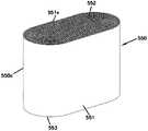
在又一个方面,提供了一种过滤器元件,所述过滤器元件包括:过滤介质的管状区段,所述过滤介质的管状区段限定开放的过滤器内部;以及固定到所述过滤介质的第一开放端帽和相反的第二端帽;所述第二端帽具有中心集成垫圈和密封构件;所述密封构件具有向内径向指向的密封表面和沿着所述密封构件表面变化的厚度。In yet another aspect, a filter element is provided, the filter element comprising: a tubular section of filter media defining an open filter interior; and a filter affixed to the filter media a first open end cap and an opposing second end cap; the second end cap having a central integrated gasket and a sealing member; the sealing member having an inward radially directed sealing surface and a varying thickness along the sealing member surface .
在示例实施例中,所述厚度沿着所述密封构件表面在径向方向上变化。In example embodiments, the thickness varies in a radial direction along the sealing member surface.
在示例实施例中,所述密封构件表面的长度在轴向方向上是恒定的。In an example embodiment, the length of the sealing member surface is constant in the axial direction.
在示例实施例中,所述径向指向的密封表面包括多个向外突出且轴向延伸的部分以及多个向内突出且轴向延伸的部分。In an example embodiment, the radially directed sealing surface includes a plurality of outwardly projecting and axially extending portions and a plurality of inwardly projecting and axially extending portions.
在示例实施例中,所述多个向外突出且轴向延伸的部分和所述多个向内突出且轴向延伸的部分包括弯曲部分。In example embodiments, the plurality of outwardly projecting and axially extending portions and the plurality of inwardly projecting and axially extending portions comprise curved portions.
在示例实施例中,所述第二端帽具有向内突出到所述过滤器内部中的凹入区段;并且所述集成垫圈在所述凹入区段中居中。In an example embodiment, the second end cap has a recessed section projecting inwardly into the filter interior; and the integrated gasket is centered in the recessed section.
在示例实施例中,所述集成垫圈具有小于所述第二端帽的外径的20%的外径。In an example embodiment, the integrated gasket has an outer diameter that is less than 20% of the outer diameter of the second end cap.
在示例实施例中,所述第一端帽具有沿着径向内表面的密封布置;并且所述密封布置包括密封支撑件和由所述密封支撑件支撑的密封构件;所述第一端帽密封构件具有向内径向指向的密封表面以及在所述密封支撑件与所述密封构件表面之间沿着所述密封构件表面变化的厚度。In example embodiments, the first end cap has a sealing arrangement along a radially inner surface; and the sealing arrangement includes a sealing support and a sealing member supported by the sealing support; the first end cap The sealing member has an inward radially directed sealing surface and a thickness that varies along the sealing member surface between the sealing support and the sealing member surface.
在示例实施例中,所述第一端帽的所述径向指向的密封表面包括多个向外突出且轴向延伸的部分以及多个向内突出且轴向延伸的部分。In an example embodiment, the radially directed sealing surface of the first end cap includes a plurality of outwardly projecting and axially extending portions and a plurality of inwardly projecting and axially extending portions.
在示例实施例中,所述过滤介质是褶皱式介质。In an example embodiment, the filter media is pleated media.
在示例实施例中,所述过滤介质的管状区段具有圆形截面。In an example embodiment, the tubular section of the filter medium has a circular cross-section.
在另一个方面,提供了一种过滤器组件,所述过滤器组件包括:管板,所述管板具有经过滤空气孔口;三脚架式轭布置,所述三脚架式轭布置固定到所述管板;所述轭布置包括杆;所述杆的一部分具有多个交替的向外径向区段和交替的向内径向区段;过滤器元件,所述过滤器元件可释放地固定到所述管板;所述过滤器元件具有:(i)第一端帽和相反的第二端帽;所述第一端帽与所述管板形成密封;(ii)过滤介质的管状区段,所述过滤介质的管状区段限定与所述经过滤空气孔口连通的内部体积;以及(iii)所述第二端帽具有集成垫圈和密封构件,所述密封构件具有多个可压缩的交替的径向突出部和交替的径向凹部和交替的径向凹部;所述第二端帽通过所述垫圈接收所述杆,这是在于:所述杆向内径向区段接收所述密封构件径向突出部;并且所述密封构件径向凹部接收所述杆向外径向区段。In another aspect, a filter assembly is provided, the filter assembly comprising: a tube sheet having filtered air apertures; a tripod yoke arrangement secured to the tube a plate; the yoke arrangement includes a rod; a portion of the rod has a plurality of alternating outward radial sections and alternating inward radial sections; a filter element releasably secured to the a tube sheet; the filter element having: (i) a first end cap and an opposing second end cap; the first end cap forming a seal with the tube sheet; (ii) a tubular section of filter media, so the tubular section of the filter media defines an interior volume in communication with the filtered air orifice; and (iii) the second end cap has an integrated gasket and a sealing member having a plurality of compressible alternating radial protrusions and alternating radial recesses and alternating radial recesses; the second end cap receives the rod through the washer in that the rod inward radial section receives the sealing member diameter and the sealing member radial recess receives the rod outward radial section.
在示例实施例中,存在固定到所述杆的自由端的可枢转手柄。In an example embodiment, there is a pivotable handle fixed to the free end of the rod.
在示例实施例中,所述管板具有沿着所述孔口的管板密封构件;所述管板密封构件具有多个交替的向外径向部分和交替的向内径向部分;并且所述第一端帽具有包括多个可压缩的交替的径向突出部和交替的径向凹部的第一过滤器元件密封构件;所述第一过滤器元件密封构件与所述管板密封构件形成密封,这是在于:所述管板密封件向内径向部分接收所述第一过滤器元件密封构件径向突出部;并且所述第一过滤器元件密封构件径向凹部接收所述管板密封构件向外径向部分。In example embodiments, the tube sheet has a tube sheet sealing member along the aperture; the tube sheet sealing member has a plurality of alternating outward radial portions and alternating inward radial portions; and the The first end cap has a first filter element seal member including a plurality of compressible alternating radial projections and alternating radial recesses; the first filter element seal member forms a seal with the tube sheet seal member , which is that: the inward radial portion of the tube sheet seal receives the first filter element seal member radial protrusion; and the first filter element seal member radial recess receives the tube sheet seal member Outward radial section.
在另一个方面,提供了一种过滤器元件,所述过滤器元件包括:过滤介质的管状区段;以及In another aspect, a filter element is provided, the filter element comprising: a tubular section of filter media; and
第一端帽,所述第一端帽固定到所述过滤介质;所述第一端帽具有沿着径向内表面的密封布置;所述密封布置包括密封构件,所述密封构件具有向内径向指向的密封表面和沿着所述密封构件表面变化的厚度;以及第二端帽,所述第二端帽与所述第一端帽相反地固定到所述过滤介质;所述第二端帽是闭合的,除了在所述第二端帽的中心的密封件接收开口;所述密封件接收开口具有小于所述第二端帽的外径的20%的外径。a first end cap secured to the filter medium; the first end cap having a sealing arrangement along a radially inner surface; the sealing arrangement including a sealing member having an inward diameter a facing sealing surface and a thickness varying along the sealing member surface; and a second end cap secured to the filter media opposite the first end cap; the second end The cap is closed except for a seal receiving opening in the center of the second end cap; the seal receiving opening has an outer diameter that is less than 20% of the outer diameter of the second end cap.
在示例实施例中,所述密封构件表面的所述厚度沿着所述密封构件表面在径向方向上变化。In example embodiments, the thickness of the sealing member surface varies in a radial direction along the sealing member surface.
在示例实施例中,所述密封构件表面的长度在轴向方向上是恒定的。In an example embodiment, the length of the sealing member surface is constant in the axial direction.
在一些实现方式中,所述密封构件厚度按最小厚度和最大厚度变化,其中,所述最大厚度是所述最小厚度的至少1.1倍。In some implementations, the sealing member thickness varies by a minimum thickness and a maximum thickness, wherein the maximum thickness is at least 1.1 times the minimum thickness.
所述径向指向的密封表面可以包括多个向外突出且轴向延伸的部分以及多个向内突出且轴向延伸的部分。The radially directed sealing surface may comprise a plurality of outwardly projecting and axially extending portions and a plurality of inwardly projecting and axially extending portions.
在一些示例中,所述多个向外突出且轴向延伸的部分和所述多个向内突出且轴向延伸的部分包括弯曲部分。In some examples, the plurality of outwardly projecting and axially extending portions and the plurality of inwardly projecting and axially extending portions comprise curved portions.
在示例实施例中,所述过滤介质是褶皱式介质。In an example embodiment, the filter media is pleated media.
在示例实施例中,所述过滤介质的管状区段具有圆形截面。In an example embodiment, the tubular section of the filter medium has a circular cross-section.
期望产品特征或方法的多种示例在以下描述中阐明,并且部分地将从描述中显而易见,或者可以通过实践本披露内容的各方面来学习。本披露内容的各方面可以涉及单独特征以及特征的组合。应当理解,上述总体描述和以下详细描述两者仅仅是说明性的,并且不限制所要求保护的本发明。Various examples of desired product features or methods are set forth in the following description, and in part will be apparent from the description, or may be learned by practicing various aspects of the present disclosure. Aspects of the present disclosure may relate to individual features as well as combinations of features. It is to be understood that both the foregoing general description and the following detailed description are illustrative only and do not limit the invention as claimed.
附图说明Description of drawings
图1是利用根据本披露内容的原理构造的过滤器元件和组件的燃气轮机进气系统的示意图;1 is a schematic diagram of a gas turbine air intake system utilizing filter elements and assemblies constructed in accordance with the principles of the present disclosure;
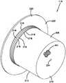
图2是根据本披露内容的原理构造的可以用于燃气轮机过滤器系统(诸如图23的系统)中的过滤器组件的透视图;2 is a perspective view of a filter assembly that may be used in a gas turbine filter system, such as the system of FIG. 23, constructed in accordance with the principles of the present disclosure;
图3是图2的组件的透视分解图;Figure 3 is a perspective exploded view of the assembly of Figure 2;
图4是图2的组件的另一个透视分解图;Figure 4 is another perspective exploded view of the assembly of Figure 2;
图5是图2的过滤器组件的侧视图;Figure 5 is a side view of the filter assembly of Figure 2;
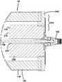
图6是图2的过滤器组件的第一实施例的截面图,该截面是沿着图5的线A-A截取的;Fig. 6 is a cross-sectional view of the first embodiment of the filter assembly of Fig. 2, the cross-section being taken along line A-A of Fig. 5;
图7是图6的过滤器组件的一部分并从图6旋转90°的放大透视图;Figure 7 is an enlarged perspective view of a portion of the filter assembly of Figure 6 and rotated 90° from Figure 6;
图8是图7中所描绘的组件的部分的另一透视图;Figure 8 is another perspective view of the portion of the assembly depicted in Figure 7;
图9是图7和图8的组件的另一部分的透视图;Figure 9 is a perspective view of another portion of the assembly of Figures 7 and 8;
图10是在图6的组件中使用的过滤器元件的端帽中的一个的放大透视图;Figure 10 is an enlarged perspective view of one of the end caps of the filter element used in the assembly of Figure 6;
图11是在图6的组件中使用的过滤器元件的截面图;Figure 11 is a cross-sectional view of a filter element used in the assembly of Figure 6;
图12是在图7和图8的组件中示出的密封板的透视图;Figure 12 is a perspective view of the seal plate shown in the assembly of Figures 7 and 8;
图13是图12的密封板的另一透视图;Figure 13 is another perspective view of the seal plate of Figure 12;
图14是图12的密封板的前视图;Figure 14 is a front view of the seal plate of Figure 12;
图15是在图3和图4的过滤器组件中使用的组件盖的透视图;Figure 15 is a perspective view of an assembly cover used in the filter assembly of Figures 3 and 4;
图16是图15的组件盖的截面图;Figure 16 is a cross-sectional view of the assembly cover of Figure 15;
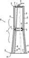
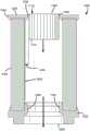
图17是可以在图1或图23的系统中使用的过滤器组件的第二实施例的分解透视图;Figure 17 is an exploded perspective view of a second embodiment of a filter assembly that may be used in the system of Figure 1 or Figure 23;
图18是图17的组件的另一透视图;Figure 18 is another perspective view of the assembly of Figure 17;
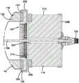
图19是图17和图18的过滤器组件的截面图,该截面是沿着图5的线A-A截取的,其中图5具有与图6和图19的组件相同的向外组装的外观;Figure 19 is a cross-sectional view of the filter assembly of Figures 17 and 18, taken along line A-A of Figure 5, wherein Figure 5 has the same outwardly assembled appearance as the assembly of Figures 6 and 19;
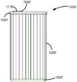
图20是在图17至图19的组件中使用的附加过滤器滤芯的透视图;Figure 20 is a perspective view of an additional filter cartridge used in the assembly of Figures 17-19;
图21是图20的过滤器滤芯的侧视图;Figure 21 is a side view of the filter cartridge of Figure 20;
图22是在图20和图21的附加过滤器滤芯中使用的过滤介质的示意透视图;Figure 22 is a schematic perspective view of filter media used in the additional filter cartridge of Figures 20 and 21;
图23是利用根据本披露内容的原理构造的过滤器元件和组件的另一燃气轮机进气系统的示意图;23 is a schematic diagram of another gas turbine air intake system utilizing filter elements and assemblies constructed in accordance with the principles of the present disclosure;
图24是可以在图1的系统中使用的另一过滤器组件的截面图;Figure 24 is a cross-sectional view of another filter assembly that may be used in the system of Figure 1;
图25是不同于图17至图19的组件的替代过滤器组件100的放大截面图;Figure 25 is an enlarged cross-sectional view of an
图26是不同于图17至图19的组件的另一替代过滤器组件100的放大截面图;Figure 26 is an enlarged cross-sectional view of another
图27是图22中所描绘的介质类型的一部分的放大示意截面图。FIG. 27 is an enlarged schematic cross-sectional view of a portion of the media type depicted in FIG. 22 .
图28包括针对图22和图27的类型的介质的各种带槽纹介质定义的示例的示意图。28 includes schematic diagrams of examples of various fluted media definitions for media of the type of FIGS. 22 and 27 .
图29是用于制造图22、图27和图28的类型的介质的示例过程的示意图。29 is a schematic diagram of an example process for manufacturing media of the type of FIGS. 22, 27, and 28. FIG.
图30是用于图22和图27至图29的类型的介质槽纹的可选端部矢状物的示意截面图。30 is a schematic cross-sectional view of an alternative end sagittal for a media flute of the type of FIGS. 22 and 27-29.
图31是可用于过滤器滤芯中的卷绕式过滤器布置的示意透视图,该过滤器滤芯具有根据本披露内容的特征并且由例如根据图22的介质条带制成。FIG. 31 is a schematic perspective view of a wrap-around filter arrangement that may be used in a filter cartridge having features according to the present disclosure and made from, for example, a strip of media according to FIG. 22 .
图32是可用于过滤器布置中的堆叠式介质包布置的示意透视图,该过滤器布置具有根据本披露内容的所选择的特征并且由例如根据图22的介质条带制成。32 is a schematic perspective view of a stacked media pack arrangement that may be used in a filter arrangement having selected features in accordance with the present disclosure and made from, for example, a strip of media in accordance with FIG. 22 .
图33是使用图22的介质的替代介质并且替代性地可用于根据本披露内容的所选择的过滤器滤芯中的过滤介质包的示意流动端视图。33 is a schematic flow end view of a filter media pack using an alternative media to the media of FIG. 22 and alternatively usable in selected filter cartridges in accordance with the present disclosure.
图34是与图33的视图相反的示意流动端视图。FIG. 34 is a schematic flow end view opposite the view of FIG. 33 .
图35是图33和图34的介质包的示意截面图。35 is a schematic cross-sectional view of the media pack of FIGS. 33 and 34 .
图36是可用于具有根据本披露内容的特征的过滤器滤芯的介质包中的又一替代介质类型的示意局部截面图。36 is a schematic partial cross-sectional view of yet another alternative media type that may be used in a media pack of a filter cartridge having features in accordance with the present disclosure.
图37是图36的介质类型的第一变型的示意局部截面图。FIG. 37 is a schematic partial cross-sectional view of a first variation of the media type of FIG. 36 .
图38是根据本披露内容的另一可用的带槽纹片材/表面片材组合的示意局部描绘。38 is a schematic partial depiction of another usable fluted sheet/face sheet combination in accordance with the present disclosure.
图39是在介质包中示出的图38中的介质类型的局部第二示意图。Figure 39 is a partial second schematic view of the media type of Figure 38 shown in a media pack.
图40是可用于根据本披露内容的布置中的又一介质变型的示意局部平面图。40 is a schematic partial plan view of yet another medium variation that may be used in arrangements in accordance with the present disclosure.
图41是根据本披露内容的可用介质的另一变型的示意图。41 is a schematic diagram of another variation of usable media in accordance with the present disclosure.
图42是根据本披露内容的另一可用的带槽纹片材/表面片材组合的示意描绘。42 is a schematic depiction of another usable fluted sheet/face sheet combination in accordance with the present disclosure.
图43是图42中描绘的可用的带槽纹片材/表面片材组合的一部分的透视图。FIG. 43 is a perspective view of a portion of the usable fluted sheet/face sheet combination depicted in FIG. 42 .
图44是可用于根据本披露内容的布置中的另一介质变型的透视图;44 is a perspective view of another medium variation that may be used in arrangements in accordance with the present disclosure;
图45A是以折叠构型示出但出于说明目的而张开或分离的图44的过滤介质的支撑区段的一部分的示意透视图;45A is a schematic perspective view of a portion of a support section of the filter media of FIG. 44 shown in a folded configuration but expanded or separated for illustration purposes;
图45B是以折叠构型示出但出于说明目的而张开或分离的图44的过滤介质的支撑区段的一部分的示意截面图;45B is a schematic cross-sectional view of a portion of a support section of the filter media of FIG. 44 shown in a folded configuration but expanded or separated for illustration purposes;
图46是可用于根据本披露内容的布置中的另一介质变型的透视图。46 is a perspective view of another medium variation that may be used in arrangements in accordance with the present disclosure.
图47是图48的过滤器布置的部分的透视分解图;Figure 47 is a perspective exploded view of a portion of the filter arrangement of Figure 48;
图48是根据本披露内容的原理构造的过滤器布置的透视图;48 is a perspective view of a filter arrangement constructed in accordance with the principles of the present disclosure;
图49是根据本披露内容的原理构造的过滤器布置的替代实施例的端视图;49 is an end view of an alternate embodiment of a filter arrangement constructed in accordance with the principles of the present disclosure;
图50是图49的过滤器布置的透视图;Figure 50 is a perspective view of the filter arrangement of Figure 49;
图51是图49的过滤器布置的侧立面图;Figure 51 is a side elevational view of the filter arrangement of Figure 49;
图52是根据本披露内容的原理构造的过滤器布置的替代实施例的端视图;52 is an end view of an alternative embodiment of a filter arrangement constructed in accordance with the principles of the present disclosure;
图53是根据本披露内容的原理构造的过滤器布置的替代实施例的端视图;53 is an end view of an alternate embodiment of a filter arrangement constructed in accordance with the principles of the present disclosure;
图54是可与燃气轮机进气系统一起使用的过滤器布置的替代实施例的透视图;54 is a perspective view of an alternate embodiment of a filter arrangement that may be used with a gas turbine air intake system;
图55是图54的过滤器布置的一部分的透视截面图;Figure 55 is a perspective cross-sectional view of a portion of the filter arrangement of Figure 54;
图56是图54和图55的过滤器布置的部分的分解透视和局部截面图;Figure 56 is an exploded perspective and partial cross-sectional view of a portion of the filter arrangement of Figures 54 and 55;
图57是被构造成与图10的管板的密封板接合的过滤器滤芯的透视图;Figure 57 is a perspective view of a filter cartridge configured to engage the sealing plate of the tube sheet of Figure 10;
图58是图57的过滤器滤芯的端视图;Figure 58 is an end view of the filter cartridge of Figure 57;
图59是图58的过滤器滤芯沿着线59-59截取的截面图;Figure 59 is a cross-sectional view of the filter cartridge of Figure 58 taken along line 59-59;
图60是图58的过滤器滤芯沿着线60-60截取的截面图;并且Figure 60 is a cross-sectional view of the filter cartridge of Figure 58 taken along line 60-60; and
图61是图60的过滤器滤芯的端件沿着线61-61截取的截面图。61 is a cross-sectional view of the end piece of the filter cartridge of FIG. 60 taken along line 61-61.
具体实施方式Detailed ways
A.系统,图1和图23A.System, Figures 1 and 23
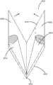
图1和图23以20描绘了两种类型的示例燃气轮机进气系统(过滤器系统)。图1的系统包括水平定向的过滤器元件,而图23的系统包括竖直定向的过滤器元件。共同的部分将使用相同的附图标记。1 and 23 depict two types of example gas turbine air intake systems (filter systems) at 20 . The system of FIG. 1 includes a horizontally oriented filter element, while the system of FIG. 23 includes a vertically oriented filter element. Common parts will use the same reference numerals.
在图1中,系统20包括腔室21,该腔室具有空气入口侧22和空气出口侧23。空气通过沿着空气入口侧22定位的多个竖直隔开的入口罩26进入腔室21。虽然不是必需的,但入口罩26起到保护系统20的内部过滤器不受雨、雪和太阳影响的作用。此外,入口罩26被构造成使得进入入口罩26的空气首先沿箭头27指示的向上方向引导,然后通过偏转板28沿箭头29指示的向下方向偏转。空气最初向上移动导致空气流中的一些颗粒物质和水分沉淀或积聚在入口罩26的下部区域30上。空气随后向下移动迫使腔室21内的粉尘向下朝向位于腔室21底部的集尘料斗32移动。还应当注意,空气入口侧22可以具有叶片和其他机械水分分离器入口。In FIG. 1 , the
系统20的腔室21被管板38(也称为隔板38)分成上游体积34和下游体积36,该管板在图1的实施例中竖直定向并且在图23的实施例中水平定向。上游体积34通常表示空气滤清器系统20的“污浊空气区段”,而下游体积36通常表示系统20的“清洁空气区段”。管板38限定多个孔口40,以用于允许空气从上游体积34流向下游体积36。每个孔口40被过滤器对41覆盖,该过滤器对包括圆柱形元件42和圆锥形元件43。在其他实施例中,过滤器对41可以包括两个圆柱形元件;或者替代性地,代替过滤器对41,可以仅存在单个元件,诸如圆柱形元件42。在图1中,圆锥形空气过滤器元件43覆盖孔口40。元件42和43两者都位于腔室的上游体积34中。过滤器元件42、43被布置和构造成使得从上游体积34流向下游体积36的空气在穿过孔口40之前穿过过滤器元件42、43。The
下文进一步描述示例过滤器元件42。
一般来说,在过滤期间,空气从上游体积34被引导穿过过滤器元件42。经过滤后,空气经由孔口40流过管板38而进入下游的清洁空气体积36。清洁空气然后从下游体积36抽出并进入燃气轮机进气口(未示出)。在图1的系统20中,元件42可以被脉冲清洁以引导空气脉冲向后穿过元件42的内部,以便逐出元件42的上游部分上的物质。脉冲射流空气滤清器可以从腔室21的顶部到底部顺序地操作,以便最终将从过滤器吹出的粉尘颗粒物质引导到下部料斗32中以进行去除。在许多空气脉冲射流清洁应用中,可用的空气压力通常在60至1500psi的范围内。Generally, during filtration, air is directed through the
在图23的实施例中,管板38是水平的。在图23的系统20中,管板38的每个孔口40包括文丘里管46,以用于引导安装在下游体积36中的空气的脉冲射流空气。周期性地操作脉冲射流空气滤清器以便将空气的脉冲射流向后引导穿过文丘里管46并进入相关联的空气过滤器元件42的内部,以逐出被捕集在空气过滤器元件42中或上的特定物质。要过滤的空气在入口侧22向上流动、然后穿过元件42、然后穿过文丘里管46、进入下游体积36、并通过出口48离开。In the embodiment of Figure 23, the
B.示例组件,图2至图4、图17、图18和图24B.Example Components, Figures 2-4, Figures 17, 18, and 24
图2是可以在图23的系统20中使用的过滤器组件100的透视图。图24示出了当过滤器对41在图1的系统中使用时的过滤器组件100的截面图。过滤器组件100可以具有许多不同的实施例。一个示例实施例是在图3和图4中;而另一示例实施例是在图17和图18中;另一示例实施例在图24中示出;另一示例性实施例在图54至图56中示出;并且另一示例实施例是在图57至图61中。这些过滤器组件100具有共同的部件,并且相同的附图标记将用于示出相同的部件(除了图57至图61的实施例,该实施例使用不同的附图标记)。每个组件的描述将不针对每个实施例进行重复,而是将基于附图标记通过援引并入。FIG. 2 is a perspective view of a
在图2中,可以看出过滤器元件42邻近管板38可操作地安装。如将在下文进一步解释,元件42被密封到密封板106,该密封板抵靠管板38。在图2中还可见可枢转手柄102,该可枢转手柄是用于将过滤器元件42可移除地固定到管板38的轭组件的部分。手柄102可以类似于在U.S.8,956,434和U.S.2017/0173512中所描述的手柄,它们中的每一个通过援引以其全部内容并入本文。In FIG. 2 , it can be seen that the
在图3、图17和图24的实施例中,管板38中的孔口40(图1)包括管板密封构件104。管板密封构件104沿着孔口40并且附接到管板38。该管板密封构件可释放地密封到过滤器元件42,如下文进一步描述。许多示例是可能的,并且在图3、图17和图24的示例实施例中,管板密封构件104是密封板106的一部分。密封板106在下文进一步描述,并且用于将管板密封构件104附接到管板38。In the embodiments of FIGS. 3 , 17 and 24 , the apertures 40 ( FIG. 1 ) in the
在图3和图17中还可见杆108,该杆可以由固定装置110保持,该杆是用于将过滤器元件42可释放地保持到管板38的轭组件的部分。图24包括支腿三脚架109,其为用于将过滤器对41可释放地保持到管板38的轭组件的部分。Also visible in FIGS. 3 and 17 is a
图3、图24和图17的组件100之间的不同之处是位于过滤器元件42的与连接到管板38的端部相反的端部处的组件。在图3和图24的组件中,存在组件盖112。组件盖112(下文进一步描述)覆盖过滤器元件42的端部并且接收杆108(图3)或三脚架支腿109(图24),以允许包括手柄102的轭组件将过滤器元件42(图3)或过滤器对41(图24)可释放地固定到管板38。如在图3中还可以看到,存在垫圈垫片114,该垫圈垫片与手柄102接合并且有助于将过滤器元件42可释放地锁定到管板38。The difference between the
在图17的实施例中,代替组件盖112,存在第二或附加过滤器滤芯116。附加过滤器滤芯116覆盖过滤器元件42的与管板38相反的开放端,并且提供用于附加过滤。这在下文进一步描述。附加过滤器滤芯116允许杆108穿其而过并且与手柄102和垫圈垫片114接合。In the embodiment of FIG. 17, in place of the
C.示例过滤器元件C.Example filter element
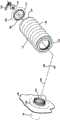
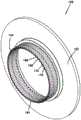
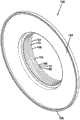
现在进一步描述过滤器元件42的示例实施例。过滤器元件42包括过滤介质118的管状区段。在这个实施例中,介质118的管状区段是圆柱形的并且具有圆形截面。在其他实施例中,管状形状可以是非圆柱形的并且具有卵形或椭圆形截面。Example embodiments of
在这个实施例中,介质118是褶皱式介质120。褶皱式介质120可以由纤维素制成。许多替代方案是可能的。In this embodiment,
过滤器元件42进一步包括第一端帽122和相反的第二端帽124。过滤介质118固定到第一端帽122和第二端帽124并且在它们之间延伸。The
第一端帽122是开放端帽,因为它具有与由介质118的管状区段限定的内部体积128连通的开口126。The
虽然在一些实施例中,第二端帽124可以是闭合端帽,但在所描绘的实施例中,第二端帽124是限定开口130的开放端帽。开口130与内部体积128连通。下文讨论关于第一端帽122和第二端帽124的更多细节。While in some embodiments the
内衬132在第一端帽122与第二端帽124之间延伸。如将在下文进一步描述,内衬132有助于防止褶皱式介质120的褶皱塌陷并且用作密封支撑件。在替代实施例中,不使用密封支撑件,并且在那些替代实施例中的一些中,不使用内衬,使得元件没有内衬。The
在这个实施例中,还存在可选的外衬134。外衬134在褶皱式介质120的外部褶皱尖端的径向外侧,并且在第一端帽122与第二端帽124之间延伸。外衬134还可以帮助支撑褶皱。在替代实施例中,根本没有外衬。In this embodiment, an optional
在图2至图5中,可以看出,在这个实施例中,如何在褶皱式介质120的外部周围具有可选的缠绕珠粒136。缠绕珠粒136可以包括例如胶带或热熔粘合剂。缠绕珠粒136将有助于支撑褶皱并且防止褶皱塌陷。In Figures 2-5 it can be seen how, in this embodiment, there is an
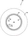
现在参考图10和图11,进一步讨论了第一端帽122和第二端帽124。在图24的实施例中,圆锥形元件被示出为具有第一端帽122'和第二端帽124'。因为这些端帽122'、124'与圆锥形元件43一起使用,所以它们与端帽122、124成比例地变化。然而,应当理解,对端帽122、124的描述通常适用于端帽122'、124',除了端帽122'、124'彼此不同并且将成比例地变化。端帽122'、124'将以与端帽122、124相同的一般方式形成密封件,如接下来描述。Referring now to FIGS. 10 and 11 , the
第一端帽122和第二端帽124中的每一个具有沿着端帽122、124中的每一个的径向内表面142、144的密封布置138、140。虽然许多变化是可能的,但在所示的优选实施例中,密封布置138、140是相同的,因为它们具有彼此相同的形状。以这种方式,过滤器元件42可以以任何取向安装在系统20中。也就是说,在这个实施例中,无关紧要的是第一端帽122还是第二端帽124与管板38连接。(如上文指出,对于圆锥形元件43而言并非如此,其中端帽122'是连接到管板38的唯一端部。)第一端帽122和第二端帽124两者都可附接到管板38。同样地,在管板38的相反端,第一端帽122或第二端帽124中的任一个可附接到其他部件,包括例如组件盖112(图3和图24)或附加过滤器滤芯116(图17)。在图24中,元件42具有均可附接到组件盖112或圆锥形元件43的端帽122、124。Each of the
因为在这个实施例中,密封布置138、140是相同的,所以将对每一个使用相同的附图标记和描述。应当理解,在其他布置中,仅一个端帽将具有密封布置,而相反的端帽可以是闭合端帽或具有不同的构型。Because the sealing
密封布置138、140包括呈内衬132形式的密封支撑件,以及由密封支撑件132支撑的密封构件146。密封构件146具有向内径向指向的密封表面148,以及在密封支撑件132与密封构件表面148之间沿着密封构件表面148变化的厚度。密封构件146的厚度也可以从褶皱式介质120的内部褶皱尖端进行测量。在US 2017/0246571中描述了示例可用的密封布置,该文献通过援引以其全部内容并入本文。The sealing
如通过回顾图10可以理解,密封支撑件132(或褶皱式介质120的内部褶皱尖端)与密封构件146之间的厚度沿着密封构件表面148在径向方向上变化。密封支撑件132与密封构件表面148之间的厚度在轴向方向上是恒定的。换句话说,密封构件表面148沿着密封支撑件132的长度在轴向方向(即,大体上平行于内衬132的方向)上是相对恒定的。As can be appreciated by reviewing FIG. 10 , the thickness between the seal support 132 (or the inner pleated tip of the pleated media 120 ) and the
虽然许多变化是可能的,但密封构件的厚度按最小厚度和最大厚度变化。一般来说,最大厚度是最小厚度的至少1.1倍。许多变化是可能的。在省略了密封支撑件的实施例中,从褶皱式介质120的内部褶皱尖端测量密封构件146的厚度。While many variations are possible, the thickness of the sealing member varies by a minimum thickness and a maximum thickness. In general, the maximum thickness is at least 1.1 times the minimum thickness. Many variations are possible. In embodiments where the seal support is omitted, the thickness of the
密封布置138、140可以根据在专利公开号为US 2017/0246571中提供的密封布置的描述来设计,该专利公开通过援引并入本文。The sealing
一般来说,径向指向的密封表面148包括多个向外突出且轴向延伸的部分150以及多个向内突出且轴向延伸的部分152。虽然许多实施例是可能的,但多个向外突出且轴向延伸的部分150和多个向内突出且轴向延伸的部分152包括弯曲部分。Generally speaking, the radially directed sealing
虽然许多实施例是可能的,但在所示的一个实施例中,多个向外突出且轴向延伸的部分150与多个向内突出且轴向延伸的部分152交替。这样,密封构件146形成多个可压缩的交替径向突出部154和交替径向凹部156。While many embodiments are possible, in one embodiment shown, a plurality of outwardly projecting and axially extending
可以存在仅几个或许多部分150、152。例如,径向指向的密封表面148可以沿着围绕过滤器元件42的中心轴线158延伸的密封支撑件132每英寸包括与至少两个径向向内突出且轴向延伸的部分152相交替的至少两个径向向外突出且轴向延伸的部分150。在许多情况下,径向指向的密封表面148包括与多于20个径向向内突出且轴向延伸的部分152相交替的多于20个径向向外突出且轴向延伸的部分150。There may be only a few or
在替代实施例中,第二端帽124是闭合的,除了位于中心的小开口,该小开口接收不可移除或可移除的密封件。第一端帽122包括密封布置138。中心的小开口可以具有小于第二端帽的外径的20%的直径。在一些实施例中,中心的小开口可以接收围绕轴的用于固位的密封垫片,其中在轴与孔之间形成密封。替代性地,可以将密封件模制到孔中。In an alternate embodiment, the
D.管板部件和轭组件D.Tube Sheet Components and Yoke Assemblies
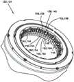
将注意力指向图7和图8,它们示出了过滤器元件42如何可释放地附接到管板38的示例实施例。如先前提及,组件100包括密封板106。在图12至图14中示出密封板106的进一步视图。Attention is directed to FIGS. 7 and 8 , which illustrate an example embodiment of how the
密封板106包括管板密封构件104,管板密封构件104限定穿其而过的内部开口160。当密封板106可操作地安装到管板38时,开口160与管板38中的孔口40连通。The sealing
在这个实施例中,密封板106包括套环162和颈部164。套环162包括抵靠并邻近管板38的外轮缘166。在这个实施例中,套环162大体上沿着管板38延伸并且可以大体上平行于管板38,但变化是可能的。In this embodiment, the
颈部164从套环162轴向突出并且外接开口160。管板密封构件104通常沿着颈部164并且可以是它的一部分。颈部164在与轮缘166从套环162延伸的方向相反的轴向方向上延伸。A
管板密封构件104成形为与密封布置138、140可释放地密封。在这个实施例中,管板密封构件104具有多个交替的向外径向部分168和交替的向内径向部分170。如在图12至图14中可以看到,存在多于20个向外径向部分168和向内径向部分170。在这个实施例中,向外径向部分168和向内径向部分170基本上在颈部164的整个长度上延伸。The tube
当过滤器元件42可移除地附接到管板38时,密封构件146与管板密封构件104形成密封,这是在于:管板密封构件104向内径向部分170接收第一过滤器元件密封构件径向突出部154;并且具有径向凹部156的密封构件146接收管板密封构件104向外径向部分168。这种连接有助于确保形成良好的密封,并且确保正确的过滤器元件42安装在过滤器组件100内。When the
再次参考图7和图8,过滤器组件100包括轭板172。轭板172的附加视图可以在图9中看到。轭板172在管板38的清洁侧上(在与固定过滤器元件42相反的侧上)固定到管板。图9从图中省略了管板的存在,以增强清晰度。Referring again to FIGS. 7 and 8 , the
轭板172限定开口174,该开口通常与管板38中的孔口40和密封板106中的开口160同轴地对准。The
轭板172包括包围开口174的周围条带176。条带176通常是平坦的并且抵靠管板138,但变化是可能的。The
条带176可以包括多个孔178。孔178容纳诸如螺栓180的紧固件。螺栓180延伸穿过文丘里管46的一部分,并将文丘里管46固定到管板38。
轭板172包括跨开口174在条带176的边缘之间的延伸的弦部。在这个示例中,弦部182跨开口174的几何中心延伸,但在其他实施例中,可以进行变化。弦部182包括用于可移除地保持杆108的固定装置110。如在图9中可以看到,存在用于保持杆108的垫圈垫片184,该垫圈垫片是固定装置110的一部分。The
杆108利用垫圈垫片108和轭板172固定到管板38。杆108延伸穿过过滤器元件42的内部体积128并且穿过组件盖112或附加过滤器滤芯116,具体取决于实施例。
杆108的端部包括径向突出部186、187(图3和图4)。径向突出部186、187与手柄102接合,使得当手柄102在锁定位置(图2)枢转并且抓握部分188(图2)大体上径向向外指向时,过滤器元件42通过径向密封件被密封到管板密封构件104。当手柄102处于释放位置并且抓握部分188大体上指向轴向方向时,杆108上的突出部186、187不与手柄102紧密接合,并且可以通过移除手柄102并移除垫圈垫片114来将过滤器元件42从管板密封构件104和管板38移除。The ends of the
在图24的实施例中,圆柱形元件42和圆锥形元件43沿着连接件52密封在一起。连接件52可以被成形为由端帽124'和端帽122接收并且与它们形成密封;替代性地,连接件52可以在元件42与43之间形成轴向插入物,以便在它们之间形成轴向密封。In the embodiment of FIG. 24 , the
E.示例组件盖E.Example Component Cover
如先前提及,在图3和图4的实施例中,过滤器组件100包括组件盖112。在图15和图16中示出组件盖112的进一步视图。As previously mentioned, in the embodiment of FIGS. 3 and 4 , the
现在参考图15和图16,组件盖112包括周围壁190。壁190从端板192延伸。一般来说,壁190垂直于端板192。壁190的尺寸被设定成延伸到第二端帽124的开口130中(或替代性地,当过滤器元件42轴向反转时,延伸到第一端帽122的开口126中)。Referring now to FIGS. 15 and 16 , the
端板192的尺寸被设定成在第二端帽124(或当元件42反转时,第一端帽122)的轴向端部上方延伸并且覆盖该轴向端部。The
端板192包括在中心穿其而过的孔口194。孔口194允许杆108通过。The
在图16中,可以看出端板192如何包括最外侧边沿196,该最外侧边沿通常是平面且平坦的。周围壁190从边沿196的内表面198延伸。In Figure 16, it can be seen how the
沿着边沿196径向向内并且在壁190延伸的位置处径向向内延伸的端板192包括凹形区段200。凹形区段200向内延伸以便处于周围壁190内。在凹形区段200的中心是孔口194。许多实施例是可能的。The
组件盖112包括多个交替的向外径向部分202和交替的向内径向部分204。在所示的实施例中,向外径向部分202和向内径向部分204是周围壁190的一部分。这样,组件盖112可以用于与第二端帽124(替代性地,与第一端帽122)形成密封。可以在元件42与组件盖112之间通过以下方式形成可释放的密封:使组件盖112的向内径向部分204接收密封构件径向突出部154;并且使密封构件径向凹部156接收组件盖112的向外径向部分202。The
F.示例性附加过滤器滤芯F.Exemplary Additional Filter Cartridges
如先前提及,在图17至图19的实施例中,组件100包括附加过滤器滤芯116。在图20和图21中描绘附加过滤器滤芯116的附加视图。在图25和图26中示出替代实施例。As previously mentioned, in the embodiment of FIGS. 17-19 , the
附加过滤器滤芯116由z形过滤介质401制成。过滤介质401可以用于形成“z形过滤器构造”。如本文中使用的术语“z形过滤器构造”旨在包括(但不限于)一种类型的过滤器构造,其中使用波纹状、折叠式或以其他方式形成的过滤器槽纹中的单独过滤器槽纹(典型地与表面介质组合)来限定成组的纵向(典型地平行的)入口和出口过滤器槽纹以用于穿过介质的流体流。以下文献中提供了z形过滤介质的一些示例:美国专利5,820,646;5,772,883;5,902,364;5,792,247;5,895,574;6,210,469;6,190,432;6,350,291;6,179,890;6,235,195;Des.399,944;Des.428,128;Des.396,098;Des.398,046;以及Des.437,401;这些引用的参考文献中的每一个均通过援引并入本文。
一种类型的z形过滤介质利用连结在一起的两个特定介质部件来形成介质构造。两个部件是:(1)带槽纹(典型地波纹状)介质片材或片材区段,以及(2)表面介质片材或片材区段。表面介质片材典型地是非波纹状的,然而它可以是波纹状的,例如垂直于槽纹方向,如2004年2月11日提交并且在2005年8月25日作为PCT WO 05/077487公开的美国临时申请60/543,804中所描述的,该申请通过援引并入本文。One type of z-shaped filter media utilizes two specific media components joined together to form a media construction. The two components are: (1) a fluted (typically corrugated) media sheet or sheet segment, and (2) a facing media sheet or sheet segment. The surface media sheet is typically non-corrugated, however it may be corrugated, eg perpendicular to the flute direction, as filed Feb. 11, 2004 and published Aug. 25, 2005 as PCT WO 05/077487 as described in
带槽纹介质区段和表面介质区段可以彼此之间包含单独材料。然而,它们还可以是单个介质片材的区段,这些区段被折叠成使表面介质材料与介质的带槽纹介质部分处于适当的并置位置。The fluted media segments and the face media segments may contain separate materials from each other. However, they may also be sections of a single sheet of media that are folded so that the surface media material is in proper juxtaposition with the fluted media portion of the media.
带槽纹(典型地波纹状)介质片材和表面介质片材或片材区段一起典型地用于限定具有平行槽纹的介质。在一些实例中,带槽纹片材和表面片材是分开的,然后固定在一起,然后作为介质条被卷绕以形成z形过滤介质构造。此类布置例如在U.S.6,235,195和6,179,890中进行了描述,这些文献中的每一个均通过援引并入本文。在某些其他布置中,固定到表面介质的带槽纹的(典型地波纹状)介质的一些非卷绕区段或条彼此堆叠,以形成过滤器构造。这种过滤器构造的示例在US 5,820,646的图11中进行了描述,该文献通过援引并入本文。Fluted (typically corrugated) media sheets and facing media sheets or sheet segments together are typically used to define media with parallel flutes. In some examples, the fluted sheet and facing sheet are separated, then secured together, and then rolled as a media strip to form a z-shaped filter media configuration. Such arrangements are described, for example, in U.S. 6,235,195 and 6,179,890, each of which is incorporated herein by reference. In some other arrangements, some non-coiled segments or strips of fluted (typically corrugated) media secured to the surface media are stacked on top of each other to form a filter construction. An example of such a filter configuration is described in Figure 11 of US 5,820,646, which is incorporated herein by reference.
在本文中,包括固定到波纹状片材的带槽纹片材(具有脊部的介质片材)的材料条(这些材料条随后被组装成叠层以形成介质包)有时被称为“单面层条”、“单面条”或者被称为“单面层”介质或“单面”介质。术语及其变体旨在是指以下事实:在每个条中,带槽纹的(典型地波纹状)片材的一个面(即,单个面)与表面片材面对面。In this document, strips of material comprising fluted sheets (media sheets with ridges) secured to corrugated sheets (these strips of material are then assembled into laminates to form media packs) are sometimes referred to as "single Strips", "Single Strips" are alternatively referred to as "single-ply" media or "single-sided" media. The term and variations thereof are intended to refer to the fact that in each strip, one face (ie, a single face) of the fluted (typically corrugated) sheet faces the facing sheet.
典型地,表面片材向外地进行带槽纹片材/表面片材(即,单面层)组合的条围绕其自身的卷绕以形成卷绕式介质包。用于卷绕的一些技术在2003年5月2日提交的美国临时申请60/467,521以及2004年3月17日提交、现在作为WO 04/082795公开的PCT申请US 04/07927中进行了描述,这些文献中的每一个均通过援引并入本文。因此,所得到的卷绕式布置通常具有表面片材的一部分作为介质包的外表面。Typically, the strip of the fluted sheet/face sheet (ie, single face layer) combination is wound outwardly around itself to form a roll-to-roll media pack. Some techniques for winding are described in
本文中使用的用于指代介质结构的术语“波纹状”经常用于指代由将介质从两个波纹辊之间通过、即进入两个辊之间的辊隙或辊缝而产生的槽纹结构,这些波纹辊中的每一个都具有适当的表面特征以便在所得到的介质中造成波纹。然而,术语“波纹”并不旨在限于此类槽纹,除非明确说明它们是通过涉及介质穿过波纹辊之间的辊缝的技术产生的槽纹所导致的。术语“波纹状”旨在即使在例如通过2004年1月22日公开的PCT WO 04/007054中所描述的折叠技术形成波纹之后介质进一步被修改或变形的情况下也适用,该文献通过援引并入本文。The term "corrugated" as used herein to refer to the structure of the media is often used to refer to the grooves created by passing the media between two corrugating rolls, ie, into the nip or gap between the two rolls Each of these corrugating rolls has suitable surface features to create corrugations in the resulting media. However, the term "corrugation" is not intended to be limited to such flutes unless it is expressly stated that they result from flutes created by techniques involving the passage of media through the gap between corrugating rolls. The term "corrugated" is intended to apply even if the medium is further modified or deformed after being corrugated, such as by the folding technique described in PCT WO 04/007054, published January 22, 2004, which is incorporated by reference. into this article.
波纹状介质是特殊形式的带槽纹介质。带槽纹介质是其上延伸有(例如通过波纹成形或折叠而形成的)单个槽纹或脊部的介质。Corrugated media is a special form of fluted media. Fluted media is media that has a single flute or ridge extending thereon (eg, by corrugation or folding).
利用z形过滤介质的可维护的过滤器元件或过滤器滤芯构型有时被称为“直通流动构型”或其变体。一般来说,在此背景下意思是,可维护的过滤器元件或过滤器滤芯总体上具有入口流动端(或面)以及相反的出口流动端(或面),其中进入和离开过滤器滤芯的流动是在大体相同的直通方向上。术语“可维护”在此背景下旨在是指包含过滤器滤芯的介质,该过滤器滤芯从对应的流体(例如,空气)滤清器定期移除和更换。在一些情况下,入口流动端(或面)和出口流动端(或面)中的每一个将是大体上平坦的或平面的,并且这两者彼此平行。然而,这种情况的变型(例如非平面的面)是可能的。Serviceable filter element or filter cartridge configurations utilizing z-shaped filter media are sometimes referred to as "through flow configurations" or variations thereof. Generally, in this context it is meant that a serviceable filter element or filter cartridge generally has an inlet flow end (or face) and an opposite outlet flow end (or face), wherein the flow entering and leaving the filter cartridge The flow is in substantially the same straight-through direction. The term "serviceable" in this context is intended to refer to media containing filter cartridges that are periodically removed and replaced from a corresponding fluid (eg, air) filter. In some cases, each of the inlet flow end (or face) and outlet flow end (or face) will be substantially flat or planar, and the two are parallel to each other. However, variants of this case (eg non-planar faces) are possible.
直通流动构型(具体地用于卷绕式或堆叠式介质包)例如与可维护的过滤器滤芯、诸如美国专利号6,039,778中所示类型的圆柱形褶皱式过滤器滤芯形成对比,该专利通过援引并入本文,在褶皱式过滤器滤芯中,流动在进入和离开介质时通常会大幅度转向。也就是说,在6,039,778的过滤器中,流动穿过圆柱形侧面进入圆柱形过滤器滤芯并且接着转向穿过介质的开放端离开(在向前流动系统中)。在典型的反向流动系统中,流动穿过介质的开放端进入可维护的圆柱形过滤器滤芯并且接着转向穿过圆柱形过滤介质的侧面离开。在美国专利号5,613,992中示出了这种反向流动系统的示例,该专利通过援引并入本文。Straight-through flow configurations (specifically used in wound or stacked media packs), for example, contrast with serviceable filter cartridges, such as cylindrical pleated filter cartridges of the type shown in US Pat. No. 6,039,778, which is provided by Incorporated herein by reference, in pleated filter cartridges, the flow typically turns sharply as it enters and leaves the media. That is, in the filter of 6,039,778, the flow enters the cylindrical filter cartridge through the cylindrical sides and then turns away (in a forward flow system) through the open end of the media. In a typical reverse flow system, flow enters the serviceable cylindrical filter cartridge through the open end of the media and then turns away through the sides of the cylindrical filter media. An example of such a reverse flow system is shown in US Patent No. 5,613,992, which is incorporated herein by reference.
如本文所使用的术语“z形过滤介质构造”及其变体仅旨在包括但不一定限于以下各项中的任一项或全部:固定到(表面)介质的波纹状或以其他方式带槽纹的介质的幅板(具有介质脊部的介质),无论片材是单独的还是单个幅板的一部分,具有适当的密封(闭合)以允许限定入口槽纹和出口槽纹;和/或由这种介质构造或形成为具有入口槽纹和出口槽纹的三维网络的介质包;和/或包括此类介质包的过滤器滤芯或构造。The term "z-shaped filter media configuration" and variations thereof as used herein are merely intended to include, but not necessarily be limited to, any or all of the following: corrugated or otherwise belts secured to (surface) media A web of fluted media (media with media ridges), whether the sheet is separate or part of a single web, with appropriate seals (closures) to allow the definition of inlet and outlet flutes; and/or Media packs constructed or formed from such media as having a three-dimensional network of inlet flutes and outlet flutes; and/or filter cartridges or constructions comprising such media packs.
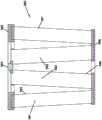
在图22中,示出了可用于z形过滤介质中的介质401的示例。介质401由波纹状(带槽纹)片材403和表面片材404形成。In Figure 22, an example of
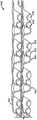
一般来说,波纹状片材403(图22)是本文中通常被表征为具有规则的、弯曲的波形图案的槽纹或波纹407的类型。术语“波形图案”在此背景下旨在是指具有交替的低谷407b和脊部407a的槽纹或波纹状图案。术语“规则的”在此背景下旨在是指以下事实:成对的低谷(407b)和脊部(407a)以大体上相同的重复波纹(或槽纹)形状和尺寸交替。(此外,典型地在规则的构型中,每个低谷407b基本上是每个脊部407a的倒置。)因此,术语“规则的”旨在指示波纹(或槽纹)图案包括低谷和脊部,其中每一对(包括相邻的低谷和脊部)重复,而波纹的尺寸和形状沿着槽纹长度的至少70%没有实质性的修改。术语“实质性的”在此背景下是指由用于创造波纹状或带槽纹片材的过程或形式的变化而产生的修改,不同于由介质片材403具有柔性的事实导致的微小变化。关于重复图案的表征,并不意味着在任何给定的过滤器构造中,必须存在相等数目的脊部和低谷。介质401可以例如在包括脊部和低谷的对之间或部分地沿着包括脊部和低谷的对终止。(例如,在图22中,局部描绘的介质401具有八个完整的脊部407a和七个完整的低谷407b。)此外,相反的槽纹端(低谷端和脊部端)可以彼此不同。除非明确规定,否则端部的此类变化在这些定义中可以忽略。也就是说,以上定义旨在涵盖槽纹端部的变化。In general, the corrugated sheet 403 (FIG. 22) is of the type of flutes or
在表征波纹的“弯曲的”波形图案的背景下,术语“弯曲的”旨在是指以下波纹图案:其不是由提供用于介质的折叠或折痕形状导致的,而是由每个脊部的顶点407a和每个低谷的底部407b沿着辐射式曲线形成的。虽然替代方案是可能的,但用于这种z形过滤介质的典型半径将为至少0.25mm,并且典型地将为不大于3mm。(根据以上定义,也可以使用非弯曲的介质。)In the context of a "curved" wave pattern characterizing corrugations, the term "curved" is intended to refer to a corrugation pattern not caused by the fold or crease shape provided for the media, but by each ridge The apex 407a and the bottom 407b of each valley are formed along a radial curve. While alternatives are possible, a typical radius for such z-shaped filter media will be at least 0.25mm, and typically will be no greater than 3mm. (According to the above definition, non-curved media can also be used.)
图22针对波纹状片材403所描绘的特定的规则的、弯曲的波形图案的附加特性是,过渡区域大致位于每个低谷与每个相邻的脊部之间的中点430处、沿着槽纹407的大部分长度,在该过渡区域中曲率反转。例如,观察背侧或面403a(图22),低谷407b是凹形区域,并且脊部407a是凸形区域。当然,当从前侧或面403b进行观察时,侧403a的低谷407b形成脊部;并且面403a的脊部407a形成低谷。(在一些情况下,区域430可以是笔直节段而不是点,其中曲率在笔直节段430的端部反转。)An additional characteristic of the particular regular, curved wave pattern depicted in FIG. 22 for
图22所示的特定的规则的、弯曲的、波形图案的波纹状片材403的特性是,各个波纹是大体上笔直的。“笔直的”在此背景下意味着贯穿边缘408与409之间的长度的至少70%(典型地至少80%),脊部407a和低谷407b的截面基本上不改变。参考图22所示的波纹图案使用的术语“笔直的”部分地将该图案与WO 97/40918以及2003年6月12日公开的PCT公开WO03/47722中的图1所描述的波纹状介质的锥形槽纹区分开,该文献通过援引并入本文。WO97/40918中的图1的锥形槽纹例如将是弯曲的波形图案,而不是“规则的”图案,或者笔直槽纹的图案,如本文中所使用的术语。The particular regular, curved, wave pattern corrugated
参考本发明的图22并且如上所述,介质401具有第一边缘408和相反的第二边缘409。当介质401被卷绕并且形成为介质包时,一般来说,边缘409将形成介质包的入口端,并且边缘408形成出口端,但如下文关于图24所讨论,相反的取向是可能的。Referring to FIG. 22 of the present invention and as described above, the
在与边缘408相邻处,片材403、404例如通过密封剂(在这种情况下,呈密封剂珠粒410的形式)彼此密封,从而将波纹状(带槽纹)片材403和表面片材404密封在一起。珠粒410在作为波纹片材403与表面片材404之间的珠粒施加以形成单面层或介质条401时有时将被称为“单面层”珠粒。密封剂珠粒410将与边缘408相邻的单个槽纹411密封闭合,以使空气从中通过。Adjacent to edge 408,
在与边缘409相邻处提供密封剂(在这种情况下,呈密封珠粒414的形式)。在与边缘409相邻处,密封珠粒414通常使槽纹415闭合以使未过滤的流体在槽纹中通过。当介质401绕其自身卷绕时,典型地将施加珠粒414,其中波纹状片材403指向内部。因此,珠粒414将在表面片材404的背侧417与波纹状片材403的侧418之间形成密封。当在将条401卷绕成卷绕式介质包的情况下施加珠粒414时,该珠粒有时将被称为“缠绕珠粒”。如果介质401被切成条并且堆叠(代替卷绕)时,珠粒414将为“堆叠珠粒”。A sealant is provided adjacent edge 409 (in this case, in the form of sealing beads 414). Adjacent to edge 409, sealing
在一些应用中,波纹状片材403也在沿着槽纹长度的各个点处粘合到表面片材4,如在线404a处所示。In some applications, the
参考图22,一旦介质401例如通过卷绕或堆叠被结合成介质包,它就可以如下操作。首先,沿箭头412的方向的空气将进入与端部409相邻的开放槽纹411。由于通过珠粒410使端部408闭合,所以空气将如箭头413所示穿过介质。空气接着可以通过穿过槽纹415的与介质包的端部408相邻的开放端415a离开介质包。当然,可以在空气沿相反方向流动的情况下进行操作,如例如关于图24所讨论。重点是在典型的空气过滤器应用中,未过滤的空气流在介质包的一端或面处进入,并且经过滤空气流在相反的端或面处离开,而没有任何未过滤的空气流穿过该包或在面之间穿过。Referring to Figure 22, once the
对于本文中在图22中所示的特定布置,平行的波纹7a、7b从边缘708到边缘709大体上完全笔直地跨过介质。笔直的槽纹或波纹可以在所选择的位置处、尤其是在端部处变形或折叠。在以上“规则的”、“弯曲的”和“波形图案”的定义中,通常忽略在槽纹端部处为了闭合而做出的修改。For the particular arrangement shown herein in Figure 22, the parallel corrugations 7a, 7b span the media substantially completely straight from edge 708 to edge 709. Straight flutes or corrugations can be deformed or folded at selected locations, especially at the ends. In the above definitions of "regular", "curved" and "wave pattern", modifications made for closure at the ends of the flutes are generally ignored.
不利用笔直的、规则的弯曲波形图案的波纹(槽纹)形状的Z形过滤器构造是已知的。例如在山田(Yamada)等人的U.S.5,562,825中示出了利用与窄V形(具有弯曲侧)出口槽纹相邻的稍微半圆形(截面)入口槽纹的波纹图案(参见5,562,825的图1和图3)。在松本(Matsumoto)等人的U.S.5,049,326中示出了由附接到具有半部分管的一个片材的具有半部分管的另一片材限定的圆形(截面)或管状槽纹,其中在所得到的平行的、笔直的槽纹之间具有平坦区域,参见松本的'326的图2。在石井(Ishii)等人的U.S.4,925,561(图1)中示出了折叠成具有矩形截面的槽纹,其中槽纹沿着其长度渐缩。在WO 97/40918(图1)中,示出了具有弯曲的波形图案(从相邻的弯曲的凸形低谷和凹形低谷)但沿其长度渐缩(并且因此不是笔直的)的槽纹或平行波纹。此外,在WO 97/40918中示出了具有弯曲的波形图案但具有不同尺寸的脊部和低谷的槽纹。Z-filter constructions are known that do not utilize a straight, regularly curved wave pattern of corrugated (fluted) shapes. A corrugation pattern utilizing slightly semicircular (cross-sectional) inlet flutes adjacent to narrow V-shaped (with curved sides) outlet flutes is shown, for example, in U.S. 5,562,825 to Yamada et al. (see Figure 1 of 5,562,825). and Figure 3). Circular (cross-section) or tubular flutes defined by one sheet with half tubes attached to another sheet with half tubes are shown in U.S. 5,049,326 to Matsumoto et al, where in The resulting parallel, straight flutes have flat areas between, see Figure 2 of Matsumoto's '326. A flute folded to have a rectangular cross-section is shown in U.S. 4,925,561 to Ishii et al. (FIG. 1), wherein the flute tapers along its length. In WO 97/40918 (Fig. 1) a flute is shown having a curved wave pattern (from adjacent curved convex and concave troughs) but tapering (and thus not straight) along its length or parallel corrugations. Furthermore, flutes having a curved wave pattern but with ridges and valleys of different sizes are shown in WO 97/40918.
一般来说,过滤介质是相对柔性的材料,典型地为(纤维素纤维、合成纤维或两者的)非织造纤维材料,其中经常包括树脂,有时是用附加材料进行处理。因此,它可以被适形成或构造成不同的波纹状图案,而没有不可接受的介质损伤。此外,它可以容易地进行卷绕或以其他方式构造以供使用,而同样没有不可接受的介质损伤。当然,它必须具有这样的性质:使得它在使用过程中将维持所要求的波纹状构型。In general, filter media are relatively flexible materials, typically non-woven fibrous materials (cellulosic fibers, synthetic fibers, or both), often including resins, and sometimes treated with additional materials. Therefore, it can be adapted or constructed into different corrugated patterns without unacceptable dielectric damage. Furthermore, it can be easily wound or otherwise constructed for use without unacceptable media damage. Of course, it must have properties such that it will maintain the desired corrugated configuration during use.
在波纹成形过程中,对介质造成非弹性变形。这防止介质恢复到其原始形状。然而,一旦张力被释放,槽纹或波纹将趋向于弹回,而仅恢复已经发生的拉伸和弯折的一部分。表面片材有时被粘合到带槽纹片材,以阻止波纹状片材的这种回弹。During the corrugation forming process, inelastic deformation is caused to the medium. This prevents the media from returning to its original shape. However, once the tension is released, the flutes or corrugations will tend to spring back, recovering only a portion of the stretching and bending that has occurred. The facing sheet is sometimes bonded to the fluted sheet to prevent this springback of the corrugated sheet.
此外,典型地,介质包含树脂。在波纹成形过程中,可以将介质加热到高于树脂的玻璃化转变温度。当树脂接着冷却时,将有助于维持带槽纹的形状。Also, typically, the medium contains resin. During corrugation, the medium can be heated above the glass transition temperature of the resin. When the resin is then cooled, it will help maintain the fluted shape.
例如根据U.S.6,673,136,具有波纹状片材403、表面片材404或两者的介质可以在其一侧或两侧上设置有细纤维材料,该文献通过援引并入本文。Media having
关于z形过滤器构造的问题涉及闭合各个槽纹端部。典型地,提供密封剂或粘合剂以实现闭合。根据上文的讨论明显的是,在典型的z形过滤介质中,尤其是使用笔直槽纹的过滤介质,与使用锥形槽纹的过滤介质不同,在上游端和下游端都需要较大密封剂表面积(和体积)。这些位置处的高质量密封对于适当地操作所形成的介质结构至关重要。较大的密封剂体积和面积造成了与此相关的问题。The problem with the z-filter construction involves closing the individual flute ends. Typically, a sealant or adhesive is provided to achieve closure. It is evident from the above discussion that in typical z-shaped filter media, especially those using straight flutes, as opposed to those using tapered flutes, larger seals are required at both the upstream and downstream ends agent surface area (and volume). High quality seals at these locations are critical to proper operation of the resulting media structures. The larger volume and area of the encapsulant creates problems associated with this.
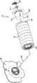
再次将注意力指向图20和图21。过滤器滤芯116包括笔直流过介质、诸如z形介质401的介质包206。介质包206包括第一流动面208和相反的第二流动面210。槽纹411、415(图22)在相反的第一流动面208与第二流动面210之间的方向上延伸。侧壁212在第一流动面208与第二流动面210之间延伸。Again, direct attention to Figure 20 and Figure 21. The
在这个实施例中,第一流动面208对应于入口流动面,而第二流动面210对应于出口流动面。In this embodiment, the
过滤器滤芯116包括围绕侧壁212的条带214。在一个示例实施例中,条带214外接并且抵靠侧壁212,但是替代方案是可能的。条带214包括多个交替的向外径向部分216和交替的向内径向部分218。The
当附加过滤器滤芯116被接收在第二端帽124内(替代性地,在第一端帽122内)时,它与端帽122、124的密封构件146形成密封,使得条带214的向内径向部分218接收密封构件径向突出部154;并且密封构件径向凹部156接收条带214的向外径向部分216。下文结合图26进一步讨论过滤器滤芯116与元件42之间的替代密封布置。When the
如在图20和图21中可以看到,条带214被定向在第一流动面208与第二流动面210之间。在这个实施例中,条带214也与第一流动面208相邻。许多实施例是可能的。As can be seen in FIGS. 20 and 21 , the
条带214可以是端件220的一部分。端件220具有从第一流动面208径向延伸的板222。条带214从板222并且沿着侧壁212轴向延伸。在这个示例实施例中,条带214大体上垂直于板222。当可操作地安装时,板222将在第二端帽124的轴向端部上方延伸并且覆盖该轴向端部。
在图25的替代实施例中,元件42和附加过滤器滤芯116在单个连续的端件240中模制在一起,使得它们是一个整体元件对242。在这个实施例中,仅元件42的第一端帽122包括密封布置138。In the alternative embodiment of FIG. 25 , the
介质包206优选是卷绕式介质包。在这个实施例中,介质包206限定在第一流动面208与第二流动面210之间并且穿过它们延伸的中央开放通道224。该通道224允许杆108延伸穿过过滤器滤芯116以便接合手柄102。参见图19。The
在这个实施例中,介质包206具有与端帽122、124的开口126、130的截面形状匹配的截面形状。在这个示例中,该形状是圆形。In this embodiment, the
附加过滤器滤芯116允许未过滤的空气流过第一流动面208。介质包206去除颗粒,并且经过滤空气流过第二流动面210,以到达过滤器元件42的内部体积128。从那里,经过滤空气流过孔口40和管板38、流过文丘里管46、并进入系统20的下游体积36(图1)。The
一般来说,附加过滤器滤芯116有助于平衡贯穿组件100的过滤器梯度,并且延长两个元件42、116的寿命。在没有过滤器滤芯116的情况下,元件42将装载在最靠近管板38的区域中,但是当使用过滤器滤芯116时,在一些系统中,空气将首先流过附加过滤器滤芯116,然后流过元件42的褶皱式介质120。这导致贯穿褶皱式介质120的过滤器梯度更加平衡,并且延长了元件42的寿命。In general, the
在图26的实施例中,代替在附加过滤器滤芯116与过滤器元件42之间在密封构件146处形成密封,过滤器滤芯116具有固定到第二流动面210的端件250。端件250具有轴向突出环252,该环在远离滤芯116的其余部分的方向上轴向延伸。环252从滤芯116的侧壁212径向向外延伸,并且其尺寸被设定成紧密地适配在端帽124的外径125周围(例如外接),以便在环252的内表面与元件42的端帽124的外径125之间并且抵靠它们形成可释放的径向密封254。In the embodiment of FIG. 26 , instead of forming a seal at the sealing
G.示例操作和方法G.Example Operations and Methods
一般来说,将要过滤的空气在罩26下方流入系统20中并且流入上游体积34中。从那里,经过滤空气流过过滤器元件42。介质118对空气进行过滤,并且经过滤空气通过管板38中的孔口40并且然后通过文丘里管46离开过滤器元件42。经过滤空气进入下游体积36,然后在那里流向燃气轮机的下游设备。Generally, the air to be filtered flows into the
在包括附加过滤器滤芯116的实施例中,如果过滤器元件42变得堵塞,则未过滤的空气将绕过褶皱式介质120,并且流过附加过滤器滤芯116的介质包206。介质包206将对空气进行过滤,并且经过滤空气将流入元件42的内部体积128,然后通过管板38中的孔口40离开。In embodiments including
周期性地,系统20将通过发射穿过文丘里管46的空气脉冲对元件42进行脉冲清洁,其中空气脉冲将进入内部体积128并且敲除或吹扫收集在褶皱式介质120的上游侧上的任何粉尘或碎屑。Periodically, the
在一段时间的操作之后,系统20将需要维护。为了维护系统120,将需要移除过滤器元件42并且用新的过滤器元件42替换。为此,通过将快速释放手柄102从锁定位置(图2和图19)枢转到解锁位置来释放过滤器元件42,在该解锁位置,手柄102被枢转以轴向延伸。将垫圈垫片114和手柄102从杆108移除。在图3和图4的实施例中,移除组件盖112,并且接着从管板38移除过滤器元件42。提供新的过滤器元件42。在具有包括相同的密封构件138、140的元件42的实施例中,将过滤器元件42的任一端朝向管板38定向。通过在第一(或第二)端帽122与管板密封构件104之间形成密封,将新的过滤器元件42抵靠管板38密封。这是通过使管板密封构件104的向外径向部分168和向内径向部分170与过滤器元件42的密封构件146的径向凹部156和径向突出部154接合来完成的。After a period of operation, the
使杆108延伸穿过组件盖112的孔口194,而组件盖的向外径向部分202和内部径向部分204与过滤器元件42的第二(或第一)端帽124的密封构件146的径向凹部156和径向突出部154形成密封。然后将垫圈垫片114和手柄102与杆108接合,并且将手柄102枢转到图2和图19的锁定位置,以便将新的过滤器元件42固定在适当的位置。The
对于图17和图18的实施例,代替与组件盖112形成密封,过滤器元件42与附加过滤器滤芯116形成密封。这是通过使条带214的向外径向部分216和向内径向部分218与元件42的密封构件146的径向凹部156和径向突出部154接合来完成的。杆108穿过通道224并且接合垫圈垫片114和手柄102,其中手柄102枢转到锁定位置以便将元件42固定到管板38。在图26中,过滤器元件42沿着端帽124的外径125在外部径向密封件254处与附加过滤器滤芯116密封。For the embodiment of FIGS. 17 and 18 , instead of forming a seal with the
H.附加的示例布置,图54至图56H. Additional Example Arrangements, Figures 54-56
除了上述布置(对所有上述布置的描述通过援引并入此处)之外,还提供了以下元件和系统。以下布置可以具有端帽、密封布置以及如先前所描述的其他各种特征中的任一个。这些特征此处不再描述。In addition to the above arrangements, the descriptions of all of which are incorporated herein by reference, the following elements and systems are provided. The following arrangements may have any of end caps, sealing arrangements, and other various features as previously described. These features are not described here.
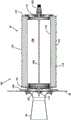
在图54至图56中,以300示出了替代系统。系统300包括过滤器布置301。过滤器布置301可以体现为单个元件42(如先前所描述),或者可以是可操作地安装在与管板38相邻处的元件对302。过滤器元件对302包括轴向对准并且端对端堆叠的圆柱形元件304和圆锥形元件305。替代性地,元件对302可以包括两个圆柱形元件。In FIGS. 54-56 , an alternative system is shown at 300 .
轭组件306(图56)将过滤器布置301可释放地保持到管板38。轭组件306包括支腿三脚架109。杆108在远离管板38的端部处从支腿三脚架109延伸。作为轭组件306的一部分的可枢转手柄102被固定到杆108的自由端,并且用于将过滤器布置301可移除地固定到管板38。手柄102可以类似于在U.S.8,956,434和U.S.2017/0173512中所描述的手柄,它们中的每一个通过援引以其全部内容并入本文。The yoke assembly 306 ( FIG. 56 ) releasably retains the
过滤器元件304具有第一端帽310和相反的第二端帽312。在过滤器布置301仅包括单个元件(诸如元件42)的实施例中,第一端帽310将与管板38形成密封,并且可以包括上文结合图4至图15所描述的密封布置138。在所示的实施例中,第一端帽310抵靠元件305的非管板端。元件305的管板端311可以包括上文结合图4至图15所描述的各种密封布置中的任一种,诸如密封布置138。替代性地,它可以是标准的轴向密封。The
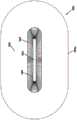
过滤器元件304的第二端帽312包括中心集成垫圈314。垫圈314由软材料制成并且包括密封构件316。密封构件316包围杆接收通孔318,杆108穿过该杆接收通孔。The
密封构件316具有向内径向指向的密封表面319和沿着密封构件表面319变化的厚度。该厚度沿着密封构件表面319在径向方向上变化。应当理解,密封表面319包围通孔318。The sealing
在图56中,可以看出径向指向的密封表面319包括多个向外突出的突出部320和多个向内突出的凹部322。这些突出部320和凹部322可以是弯曲的。在这个示例中,密封构件表面319的长度在轴向方向上是恒定的。In FIG. 56 , it can be seen that the radially directed sealing
第二端帽312具有向内突出到过滤器内部332中的凹入区段330。集成垫圈314在凹入区段330中居中。The
在所示的示例中,集成垫圈314的外径小于第二端帽312的外径。例如,集成垫圈314的直径小于第二端帽312的外径的50%、实际上小于30%、并且经常小于20%。In the example shown, the outer diameter of the
在系统300中,杆108的一部分具有多个交替的向外径向区段340和交替的向内径向区段342。第二端帽312通过垫圈314中的孔口318接收杆108,这是在于:杆的向内径向区段342接收密封构件径向突出部320;并且密封构件的径向凹部322接收杆的向外径向区段340。In
杆108与垫圈314之间的接触有助于增加过滤器元件垫圈314与杆108之间的接触,以在过滤器元件304的整个使用寿命期间确保良好的密封。突出部320和凹部322的数量可以根据所需的密封压缩系数而变化。高压清洗机可以用于帮助将夹持系统的负载分布到过滤器元件304的第二端帽312上。The contact between the
I.附加的示例布置,图57至图61I. Additional Example Arrangements, Figures 57-61
除了上述布置(对所有上述布置的描述通过援引并入此处)之外,还提供了以下元件和系统。以下布置可以具有端帽、密封布置以及如先前所描述的其他各种特征中的任一个。这些特征此处不再描述。In addition to the above arrangements, the descriptions of all of which are incorporated herein by reference, the following elements and systems are provided. The following arrangements may have any of end caps, sealing arrangements, and other various features as previously described. These features are not described here.
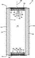
现在参考图57至图61,以附图标记2350示出了过滤器滤芯或元件(例如,初级或主过滤器滤芯或元件)。如图所示的过滤器滤芯2350包括第一端件(例如,帽)2352、第二端件(例如,帽)2354、过滤介质2356和衬垫2358。过滤介质2356包括第一端2356a和第二端2356b。一般来说,过滤介质第一端2356a可以嵌入第一端帽2352,并且过滤介质第二端2356b可以嵌入第二端帽2354。另外,衬垫2358包括衬垫第一端2358a和衬垫第二端2358b。衬垫第一端2358a也可以嵌入第一端帽2352,并且衬垫第二端2358b可以嵌入第二端帽2354。另外,过滤介质2256可以被设置为由衬垫2258支撑。过滤介质2256可以被设置为圆柱形或圆锥形褶皱式介质,或为过滤器滤芯2350提供中心开放体积2360的任何其他类型的介质构型。Referring now to FIGS. 57-61 , a filter cartridge or element (eg, a primary or primary filter cartridge or element) is shown at 2350 . The
现在参考图60至图61,详细地示出了第一端件(例如,帽)2352。第一端帽2352包括与过滤器元件中心开放体积2360连通的中心开放体积2362。因此,第一端帽2352可以被表征为开放端帽364。第二端帽2354也可以是开放端帽。Referring now to FIGS. 60-61 , the first end piece (eg, cap) 2352 is shown in detail. The
过滤器元件2350可以用于例如图1或图23的系统20中。如上文所表征的密封构件138、140在下文进一步定义,并且该进一步的定义可以应用于先前描述的密封构件138、140中的任一个。
开放端帽2364包括第一端2367、第二端2369以及在第一端2367与第二端2369之间延伸的内表面2370。内表面2370形成中心开放体积2362,并且可以被构造成接合并密封具有波形壁的管板密封构件104(图12至图14)。内表面2370可以形成内部指向的径向密封。The
如图所示的内表面2370包括导入区域2372、可选的外围均匀的径向密封区域2378、过渡区域2374和外围非均匀的径向密封区域2376。可选的外围均匀的密封径向密封区域2378可以从过滤器元件2350省略,并且在期望过滤器元件2350适配过滤器滤芯密封表面和现有技术空气管板密封构件两者的情况下提供,该过滤器滤芯密封表面可以被表征为波形壁管板密封构件,该现有技术空气管板密封构件具有围绕轴线X的外围均匀的密封表面。The
导入区域2372、过渡区域2374和外围非均匀的径向密封区域2376可以被表征为具有与多个径向向内突出且轴向延伸的部分2392交替的多个径向向外突出且轴向延伸的部分2390。这些部分2390和2392可以被设置为沿着区域2372、2374和2376中的每一个轴向地延伸并且不沿着区域2378延伸(如果区域2378存在)。径向向外突出且轴向延伸的部分2390可以被表征为低谷2394,并且径向向内突出且轴向延伸的部分2392可以被表征为顶峰或脊部2396。可以在相邻的低谷2394之间设置由顶峰2396形成的凸角2400,使得这些凸角适配在管板密封构件104(图12至图14)中的对应低谷(向内径向部分)170中。类似地,设置低谷2394,使得它们接收管板密封构件104中的顶峰(向外径向部分)168。应当理解,对“向外”和“向内”的引用是指远离或朝向中心轴线X的方向。因此,向外突出且轴向延伸的部分2390可以被称为低谷2394,并且向内突出且轴向延伸的部分2392可以被称为顶峰2396。可以贯穿引入区域2372、过渡区域2374和径向密封区域2376来改变和调节低谷2394和顶峰2396的尺寸和形状,以便容易将过滤器元件2350插入到管板密封构件104上。Lead-in
径向密封区域2376包括波形壁密封构件表面2398,该波形壁密封构件表面也包括多个凸角2400。波形壁密封构件表面可以根据“节距”来表征,该节距为从凸角2400的顶峰到相邻顶峰的距离。在波形壁密封构件表面2376的情况下,节距可以被定义为相邻顶峰之间的距离。替代性地,节距可以被定义为相邻低谷之间的距离。波形壁密封构件表面2376可以被表征为具有节距,以允许服务提供者(过滤器元件的安装方)进行一定程度的分度,从而允许服务提供者在壳体内正确地分度过滤器元件而不必重新夹紧过滤器元件。当过滤器滤芯2350被引入波形管板密封构件中时,导入区域2372接合管板密封构件104的波形壁,由此将过滤器滤芯2350分度成正确的取向以供进一步轴向插入。外围均匀的径向密封表面2378(如果存在)通过连续的轴向插入与管板密封构件104的波形壁接合。进一步轴向插入导致过渡区域2374接合波形壁,以帮助进一步使过滤器滤芯2350定向并且易于过渡到径向密封区域2376接合管板密封构件104的波形壁,在其中形成径向指向的密封件。The
应当理解,对于过滤器滤芯2350,外围非均匀的径向密封表面2376和外围均匀的径向密封表面2378(如果存在)从开放端帽2364的第一端2367凹入。此外,密封表面2376和2378可以被表征为设置在过滤介质2356的内部。此外,通过使密封表面2376和2378从第一端2367凹入,当过滤器滤芯2350被设置于脏污表面上时,保护密封表面2376和2378免遭粉尘或碎屑。例如,密封表面2376和2378可以在距第一端2367的至少约1毫米处轴向地凹入。It will be appreciated that for
在一些实施例中,第二端帽2354可以具有与如上文所表征的第一端帽2356相同的构造。In some embodiments, the
II.附加的介质构型II. ADDITIONAL MEDIA CONFIGURATIONS
A.引言A. Introduction
根据本披露内容的原理涉及过滤器滤芯与空气滤清器系统之间的相互作用,以有利的方式实现下文讨论的某些所选择的期望结果。过滤器滤芯中总体上将包括过滤介质,在过滤操作期间空气和其他气体穿过该过滤介质。介质可以具有多种类型和构型,并且可以使用多种材料制成。例如,根据本披露内容的原理,在滤芯中可以使用褶皱式介质布置,如下文所讨论。Principles in accordance with the present disclosure relate to the interaction between a filter cartridge and an air cleaner system in an advantageous manner to achieve certain selected desired results discussed below. A filter cartridge will generally include a filter medium through which air and other gases pass during a filtering operation. Media can be of various types and configurations, and can be made using a variety of materials. For example, in accordance with the principles of the present disclosure, a pleated media arrangement may be used in a filter element, as discussed below.
这些原理尤其适于在其中介质在滤芯的入口端与出口端之间延伸相当深的情况下使用,但替代方案是可能的。此外,这些原理经常用于具有相对较大截面尺寸的滤芯。在此类布置的情况下,经常希望对褶皱式介质使用替代介质类型。These principles are particularly suitable for use in situations where the medium extends considerably deep between the inlet and outlet ends of the filter element, but alternatives are possible. Furthermore, these principles are often used for filter elements with relatively large cross-sectional dimensions. In the case of such arrangements, it is often desirable to use alternate media types for pleated media.
在本节中,提供了可与本文所述的技术一起使用的一些介质布置的示例。然而,将理解可以使用多种替代介质类型。介质类型的选择总体上基于以下偏好中的一个:可用性;在给定应用情况下的功能、易制造性等,并且选择不一定与本文所表征的各种过滤器滤芯/空气滤清器相互作用特征中的所选择的特征的整体功能特定地相关。In this section, examples of some media arrangements that can be used with the techniques described herein are provided. However, it will be appreciated that a variety of alternative media types may be used. Selection of media type is generally based on one of the following preferences: availability; functionality in a given application, ease of manufacture, etc., and selection does not necessarily interact with the various filter cartridges/air cleaners characterized herein The overall function of a selected one of the features is specifically related.
上文关于图22描述了使用具有固定到表面介质的介质脊部(槽纹)的过滤介质的介质包布置。Media pack arrangements using filter media with media ridges (flutes) secured to the face media are described above with respect to FIG. 22 .
现在将注意力指向图27,其中示意性地描绘了z形过滤介质;即,利用规则的、弯曲的波形图案的波纹状片材503和非波纹状平坦片材504(即单面层条)的z形过滤介质构造500。点506与507之间的距离D1限定了平坦介质504在给定波纹状槽纹508下方的区域502中的延伸量。由于波纹状槽纹508的形状,在相同距离D1上方的波纹状槽纹508的弧形介质的长度D2当然大于D1。对于在带槽纹过滤器应用中使用的典型的规则形状的介质,介质508在点506与507之间的线性长度D2通常将是D1的至少1.2倍。典型地,D2将在D1的1.2至2.0倍的范围内,包括端值。空气过滤器的一个特别方便的布置具有其中D2为约1.25至1.35×D1的构型。例如,这种介质已经在商业上用于Donaldson PowercoreTM Z形过滤器布置中。另一种可能方便的尺寸是其中D2为D1的约1.4至1.6倍的尺寸。在本文中,比率D2/D1有时将被表征为波纹状介质的槽纹/平坦比率或介质拉伸度。Attention is now directed to Figure 27, in which a z-shaped filter media is schematically depicted; ie, a
在瓦楞纸板行业,已经定义了不同标准的槽纹。例如,标准E槽纹、标准X槽纹、标准B槽纹、标准C槽纹和标准A槽纹。附图3结合下表A提供了这些槽纹的定义。In the corrugated board industry, different standard flutes have been defined. For example, standard E flute, standard X flute, standard B flute, standard C flute, and standard A flute. Figure 3, in conjunction with Table A below, provides definitions of these flutes.
本披露内容的受让方,唐纳森公司(DCI),已经在多种z形过滤器布置中使用了标准A和标准B槽纹的变型。这些槽纹也在表A和图28中定义。Donaldson Incorporated (DCI), the assignee of the present disclosure, has used variations of Standard A and Standard B flutes in various z-filter arrangements. These flutes are also defined in Table A and Figure 28.
表ATable A

当然,来自瓦楞纸箱行业的其他标准槽纹定义也是已知的。Of course, other standard flute definitions from the corrugated box industry are also known.
一般来说,来自瓦楞纸箱行业的标准槽纹构型可以用于限定波纹状介质的波纹形状或近似波纹形状。以上DCI A槽纹与DCI B槽纹以及波纹行业标准A槽纹与标准B槽纹之间的比较指示一些方便的变型。In general, standard flute configurations from the corrugated box industry can be used to define the corrugation shape or approximate corrugation shape of the corrugated media. The above comparisons between DCI A flutes versus DCI B flutes and corrugation industry standard A flutes versus standard B flutes indicate some convenient variations.
应当注意,可以使用替代槽纹定义,诸如以下文献中表征的定义:2008年6月26日提交并且作为US 2009/0127211公开的USSN 12/215,718;2008年2月4日提交并且作为US2008/0282890公开的US 12/012,785;和/或作为US2010/0032365公开的US 12/537,069,其中具有如在本文中以下表征的空气滤清器特征。US 2009/0127211、US 2008/0282890和US2010/0032365中每一个的完整披露内容通过原因并入本文。It should be noted that alternative flute definitions may be used, such as those characterized in:
包括具有固定到其上的表面介质的带槽纹介质的另一种介质变型可以以堆叠或卷绕的形式用于根据本披露内容的布置中,描述于由宝威滤清器公司(Baldwin Filters,Inc.)所有的2014年7月31日公开的US 2014/0208705 A1中,该文献通过援引并入本文。Another media variation including fluted media having surface media secured thereto may be used in a stacked or coiled form in arrangements according to the present disclosure, described by Baldwin Filters , Inc.) in US 2014/0208705 A1 published July 31, 2014, which is incorporated herein by reference.
B.包括图22、图27和图28的介质的介质包构型的制造,参见图29至图32B. Fabrication of Media Pack Configurations Including the Media of Figures 22, 27, and 28, See Figures 29-32
在图29中,示出了用于制作对应于条1(图22)的介质条(单面层)的制造过程的一个示例。一般来说,表面片材510和具有槽纹514的带槽纹(波纹状)片材512被带到一起以形成介质幅板515,其中粘合剂珠粒在516处定位在它们之间。粘合剂珠粒516将形成单面层珠粒414(图22)。在平台518处发生可选的压凹(darting)过程,以形成位于幅板中间的中心压凹区段520。z形过滤介质或Z形介质条522可以沿着珠粒516在523处被切割或撕裂,以形成z形过滤介质522的两个片段或条524、525,该两个片段或条中的每一个具有带有在波纹成形片材与表面片材之间延伸的密封剂条(单面层珠粒)的边缘。当然,如果使用可选的压凹过程,则具有密封剂条(单面层珠粒)的边缘也将具有在此位置处压凹的一组槽纹。In Figure 29, one example of a manufacturing process for making a dielectric strip (single-sided layer) corresponding to strip 1 (Figure 22) is shown. In general, the facing
用于进行如关于图29所表征的过程的技术在2004年1月22日公开的PCT WO 04/007054中进行描述,该文献通过援引并入本文。Techniques for performing the process as characterized with respect to Figure 29 are described in PCT WO 04/007054, published January 22, 2004, which is incorporated herein by reference.
仍然参考图29,必须先形成z形过滤介质522,然后使其通过压凹平台518并且最终在523处撕裂。在图29所示的示意图中,这是通过使过滤介质片材526穿过一对波纹辊528、529来完成的。在图29所示的示意图中,将过滤介质片材526从辊530展开、围绕张力辊532缠绕、然后穿过波纹辊528、529之间的辊隙或辊缝534。波纹辊528、529具有齿536,其将在平坦片材526穿过辊隙534之后产生一般期望形状的波纹。在穿过辊隙534之后,片材526变成横跨机器方向波纹状的,并且被称为用512表示的波纹状片材。然后将波纹状片材512固定到表面片材510。(在一些情况下,波纹成形过程可能涉及对介质进行加热。)Still referring to FIG. 29 , the z-shaped
仍然参考图29,该过程还示出了表面片材510被输送到压凹处理平台518。表面片材510被描绘为储存在辊106上,然后被引导到波纹状片材512以形成Z形介质522。波纹状片材512和表面片材510典型地将通过粘合剂或其他方式(例如通过声波焊接)固定在一起。Still referring to FIG. 29 , the process also shows that the facing
参考图29,示出了用于作为密封剂珠粒将波纹状片材512和表面片材510固定在一起的粘合剂线516。替代性地,用于形成表面珠粒的密封剂珠粒可以如516a所示那样施加。如果在516a处施加密封剂,可能希望在波纹辊529中留置间隙,并且可能在两个波纹辊528、529中留置间隙,以容纳珠粒516a。Referring to Figure 29, there is shown a line of adhesive 516 used to secure the
当然,如果需要的话,图29的设备可以被修改以提供用于粘性珠粒20(图22)。Of course, the apparatus of Fig. 29 can be modified to provide for use with adhesive beads 20 (Fig. 22) if desired.
提供给波纹状介质的波纹的类型是选择问题,并且将由波纹辊528、529的波纹或波纹齿来指定。一个有用的波纹图案将是笔直槽纹或脊部的规则的弯曲波形图案的波纹,如在本文中以上所定义。所使用的典型的规则的弯曲波形图案将是这种图案:其中波纹状图案中的如以上文所定义的距离D2是如以上文所定义的距离D1的至少1.2倍。在示例应用中,典型地D2=1.25至1.35×D1,但替代方案是可能的。在一些情况下,这些技术可以应用于并非“规则的”弯曲波形图案,包括例如不使用笔直槽纹的波形图案。此外,所示的弯曲波形图案的变型是可能的。The type of corrugation provided to the corrugated media is a matter of choice and will be dictated by the corrugations or corrugation teeth of the
如所描述,图29所示的过程可以用于形成中心压凹区段520。图30以截面示出在压凹和撕裂之后的槽纹514中的一个。As described, the process shown in FIG. 29 may be used to form the central debossed
可以看到,折叠布置538形成具有四个折痕541a、541b、541c、541d的压凹槽纹540。折叠布置538包括固定到表面片材510上的平坦的第一层或部分542。第二层或部分544被示出为压靠在第一层或部分542上。第二层或部分544优选地通过与第一层或部分542的外端546、547相反地折叠而形成。It can be seen that the
仍然参考图30,折叠部或折痕541a、541b中的两个在本文中通常将被称为“上部向内指向的”折叠部或折痕。术语“上部”在此背景下旨在指示:当以图30的取向来观察折叠部540时,折痕位于整个折叠部540的上部部分上。术语“向内指向的”旨在是指以下事实:每个折痕541a、541b的折叠线或折痕线被引导朝向另一个。Still referring to Figure 30, two of the folds or folds 541a, 541b will generally be referred to herein as "upper inwardly directed" folds or folds. The term "upper" in this context is intended to indicate that the crease is located on the entire upper portion of the
在图30中,折痕541c、541d在本文中通常将被称为“下部向外指向的”折痕。术语“下部”在此背景下是指以下事实:在图30的取向上,折痕541c、541d不像折痕541a、541b那样位于顶部。术语“向外指向的”意在表示折痕541c、541d的折叠线远离彼此被引导。In Figure 30, the
如在此背景下使用的,术语“上部”和“下部”旨在具体地是指当从图30的取向进行观察时的折叠部540。也就是说,当折叠部540定向在实际产品中以供使用时,这些术语并不旨在另外指示方向。As used in this context, the terms "upper" and "lower" are intended to refer specifically to fold 540 when viewed from the orientation of FIG. 30 . That is, these terms are not intended to otherwise indicate direction when
基于图30的这些表征和评论,可以看出,根据本披露内容中的图30的规则的折叠布置538是包括至少两个“上部向内指向的折痕”的折叠布置。这些向内指向的折痕是独特的,并且有助于提供总体布置,其中折叠不会引起相邻槽纹的显著侵蚀。Based on these characterizations and comments of Figure 30, it can be seen that the
还可以看到,第三层或部分548压靠在第二层或部分544上。第三层或部分548通过与第三层548的内端550、551相反地折叠而形成。It can also be seen that the third layer or
观察折叠布置538的另一种方式是参考波纹状片材512的交替的脊部和低谷的几何形状。第一层或部分542由倒脊形成。第二层或部分544对应于朝向倒脊折叠,并且在优选的布置中抵靠倒脊折叠的双峰(在使脊部倒置之后)。Another way to look at the folded
用于提供结合图30所描述的可选的压凹的技术,以优选的方式在PCT WO 04/007054中进行描述,该文献通过援引并入本文。用于在施加缠绕珠粒的情况下卷绕介质的技术在2004年3月17日提交并且作为WO 04/082795公开的PCT申请US 04/07927中进行描述,该文献通过援引并入本文。Techniques for providing the optional indentation described in connection with Figure 30 are described in a preferred manner in PCT WO 04/007054, which is incorporated herein by reference. Techniques for winding media with the application of wound beads are described in PCT application US 04/07927, filed March 17, 2004 and published as WO 04/082795, which is incorporated herein by reference.
用于将带槽纹端部压凹闭合的替代方法是可能的。此类方法可以涉及例如:在每个槽纹中不居中的压凹;以及在不同的槽纹上滚压、按压或折叠。一般来说,压凹涉及折叠或以其他方式操纵与带槽纹端部相邻的介质,以实现压缩闭合状态。Alternative methods for crimping the fluted ends closed are possible. Such methods may involve, for example: indentations that are not centered in each flute; and rolling, pressing or folding over different flutes. In general, embossing involves folding or otherwise manipulating the media adjacent the fluted end to achieve a compressed closed state.
本文中描述的技术尤其适于通过卷绕包括波纹状片材/表面片材组合的单个片材(即,“单面层”条)的步骤所形成的介质包。然而,介质包也可以被制成堆叠式布置。The techniques described herein are particularly suitable for media packs formed by the step of winding a single sheet comprising a corrugated sheet/face sheet combination (ie, a "single ply" strip). However, media packs can also be made in a stacked arrangement.
卷绕式介质或介质包布置可以提供多种外周周边定义。在此背景下,术语“外周周边定义”及其变体旨在是指:从介质或介质包的入口端或出口端来看,所限定的外部周边形状。典型的形状是圆形,如PCT WO 04/007054中所描述。其他可用的形状是长圆形,长圆形的一些示例是卵形形状。一般来说,卵形形状具有由一对相反的边附接的相对的弯曲端部。在一些卵形形状中,相反的边也是弯曲的。在其他卵形形状(有时称为跑道形状)中,相反的边是大体上笔直的。跑道形状例如在PCT WO 04/007054和作为WO 04/082795公开的PCT申请US04/07927中描述,这些文献中的每一个均通过援引并入本文。Rolled media or media pack arrangements can provide a variety of perimeter perimeter definitions. In this context, the term "perimeter perimeter definition" and variations thereof are intended to refer to the defined outer perimeter shape as viewed from the inlet or outlet end of the media or media pack. A typical shape is circular, as described in PCT WO 04/007054. Other shapes available are ovals, some examples of which are oval shapes. Generally, an oval shape has opposing curved ends attached by a pair of opposing sides. In some oval shapes, the opposite side is also curved. In other oval shapes (sometimes referred to as racetrack shapes), the opposite sides are generally straight. Racetrack shapes are described, for example, in PCT WO 04/007054 and PCT application US04/07927 published as WO 04/082795, each of which is incorporated herein by reference.
描述外周或周边形状的另一种方式是通过限定由沿与卷绕物的缠绕进口正交的方向穿过介质包截取的截面而得到的周边。Another way to describe the perimeter or perimeter shape is by defining a perimeter resulting from a cross-section taken through the media pack in a direction normal to the winding inlet of the wrap.
可以提供介质或介质包的相反的流动端或流动面的多种不同的定义。在许多布置中,端部或端面是大体上平坦的(平面的)并且彼此垂直。在其他布置中,端面中的一个或两个包括锥形例如阶梯状部分,其可以被限定为从介质包的侧壁的轴向端部轴向向外突出;或者从介质包的侧壁的端部轴向向内突出。A number of different definitions of opposite flow ends or flow faces of media or media packs can be provided. In many arrangements, the ends or end faces are generally flat (planar) and perpendicular to each other. In other arrangements, one or both of the end faces include a tapered, eg stepped portion, which may be defined as projecting axially outwardly from the axial end of the sidewall of the media pack; or from the sidewall of the media pack The ends project axially inward.
槽纹密封件(例如,由单面层珠粒、缠绕珠粒或堆叠珠粒实现)可以由多种材料形成。在引用和结合的参考文献中的不同参考文献中,热熔密封件或聚氨酯密封件被描述为可能用于不同的应用。Fluted seals (eg, implemented with single-sided beads, tangled beads, or stacked beads) can be formed from a variety of materials. In various references in the cited and incorporated references, hot melt seals or urethane seals are described as possible for different applications.
在图31中,总体上描绘了通过卷绕单面介质的单个条而构造成的卷绕式介质包(或卷绕式介质)550。所描绘的特定卷绕式介质包是卵形介质包550a,具体地是跑道形介质包551。在介质包550的外部的介质尾端被示出为551x。为了方便和进行密封,典型地将沿着介质包550的笔直区段终止该尾端。典型地,沿着该尾端定位热熔密封珠粒或密封珠粒,以确保密封。在介质包550中,相反的流动(端)面被指定为552、553。一个将是入口流动面,另一个是出口流动面。In Figure 31, a roll media pack (or roll media) 550 constructed by winding a single strip of single-sided media is generally depicted. The particular roll media pack depicted is an oval shaped
在图32中,(示意性地)示出了由z形过滤介质条形成堆叠式z形过滤介质(或介质包)的步骤,每个条是固定到表面片材的带槽纹片材。参考图6,单面层条560被示出为添加到与条560类似的条562的叠层561。条560可以从条524、525(图29)中的任一个切割。在图31的563处,示出了在与单面层珠粒或密封件相反的边缘处、在与条带560、562相对应的每个层之间施加堆叠珠粒564。(堆叠也可以是通过将每个层被添加到叠层底部而不是顶部来完成。)In Figure 32, the steps of forming a stacked z-shaped filter media (or media pack) from strips of z-shaped filter media, each strip being a fluted sheet secured to a facing sheet, are shown (schematically). Referring to FIG. 6 , a single-
参考图32,每个条560、562具有前边缘565和后边缘566以及相反的侧边缘568a、568b。包括每个条560、562的波纹状片材/表面片材组合的入口槽纹和出口槽纹总体上在前边缘207与后边缘566之间并且平行于侧边缘568a、568b延伸。Referring to Figure 32, each
仍然参考图32,在形成的介质或介质包561中,相反的流动面以570、571指示。在过滤过程中,面570、571中哪一个是入口端面以及哪一个是出口端面的选择是选择问题。在一些情况下,堆叠珠粒564与上游或入口面571相邻定位;而在其他情况下,正好相反。流动面570、571在相反的侧面572、573之间延伸。Still referring to FIG. 32 , in the formed media or
图32中形成的所示堆叠介质构型或介质包561在本文中有时被称为“块状”堆叠介质包。术语“块状”在此背景下是指示布置形成为矩形块,其中所有面相对于所有邻接壁面成90°。例如,在一些情况下,可以通过使每个条560与相邻条的对准稍微偏移来形成叠层,以形成平行四边形或倾斜块形状,其中入口面和出口面彼此平行,但不与上下表面垂直。The illustrated stacked media configuration or
在一些情况下,介质或介质包将被称为在任何截面中具有平行四边形形状,这意味着任何两个相反的侧面总体上彼此平行地延伸。In some cases, a media or media pack will be said to have a parallelogram shape in any cross-section, which means that any two opposing sides extend generally parallel to each other.
应当注意,对应于图32的块状堆叠布置在US 5,820,646的现有技术中进行描述,该文献通过援引并入本文。还应当注意,堆叠布置在以下文献中进行描述:U.S.5,772,883;5,792,247;2003年3月25日提交的美国临时申请60/457,255;以及2003年12月8日提交并且作为2004/0187689公开的U.S.S.N.10/731,564。这些后续参考文献中的每一个均通过援引并入本文。应当注意,作为2005/0130508公开的U.S.S.N.10/731,504中所示的堆叠布置是倾斜的堆叠布置。It should be noted that the bulk stack arrangement corresponding to Figure 32 is described in the prior art of US 5,820,646, which is incorporated herein by reference. It should also be noted that stacking arrangements are described in U.S. 5,772,883; 5,792,247;
还应当注意,在一些情况下,可以将多于一个叠层结合到单个介质包中。此外,在一些情况下,可以利用其中具有凹部的一个或多个流动面来生成叠层,例如,如US 7,625,419中所示,该文献通过援引并入本文。It should also be noted that in some cases more than one stack may be incorporated into a single media pack. Furthermore, in some cases, one or more flow surfaces having recesses therein may be utilized to create a stack, eg, as shown in US 7,625,419, which is incorporated herein by reference.
C.包括多个隔开的带槽纹介质卷的所选择的介质或介质包布置;图33至图35C. Selected media or media pack arrangement comprising multiple spaced rolls of fluted media; Figures 33-35
替代类型的介质布置或介质包(在其间延伸的相反端之间包括槽纹)可以与根据本披露内容的所选择的原理一起使用。这种替代介质布置或介质包的示例在图33至图35中进行描绘。图33至图35的介质类似于DE 20 2008 017059U1中所描绘和描述的介质;并且有时可以见于以商标“IQORON”从曼·胡默尔公司(Mann&Hummel)购得的布置中。Alternative types of media arrangements or media packs (including flutes between opposing ends extending therebetween) may be used with selected principles in accordance with the present disclosure. Examples of such alternate media arrangements or media packs are depicted in FIGS. 33-35 . The media of Figures 33 to 35 are similar to those depicted and described in
参考图33,介质或介质包总体上用580表示。介质或介质包580包括第一外部褶皱式(脊形)介质环路581和第二内部褶皱式(脊形)介质环582,每个介质环具有在相反的流动端之间延伸的褶皱尖端(或脊部)。图33的视图朝向介质包(流动)端部585。根据所选择的流动方向,所描绘的端部585可以是入口(流入)端或出口(流出)端。对于使用已表征的原理的许多布置,介质包580将被构造在过滤器滤芯中,使得端部585是入口流动端。Referring to FIG. 33 , media or media packs are generally indicated at 580 . The media or
仍然参考图33,外部褶皱式(脊形)介质环581被构造成卵形形状,但是替代方案是可能的。在590处,例如被模制在适当位置的褶皱端部封闭件被描绘为在介质包端部585处封闭褶皱或脊部581的端部。Still referring to Fig. 33, the outer pleated (ridged)
褶皱或脊部582(和相关的褶皱尖端)被定位成由环581包围并且与其隔开,并且因此褶皱式介质环582也被描绘成稍微卵形的构型。在这种情况下,环582中的各个褶皱或脊部582p的端部582e被密封闭合。此外,环582包围由典型地模制在适当位置的中心材料条583封闭的中心582c。The pleats or ridges 582 (and associated pleat tips) are positioned to be surrounded by and spaced from the
在过滤过程中,当端部585是入口流动端时,空气进入两个介质环581、582之间的间隙595。然后,随着空气移动穿过介质包580进行过滤,它流过环581或环582。During filtration, air enters the
在所描绘的示例中,环581被构造成朝向环582向内倾斜而远离端部585延伸。为了结构完整性,还示出了支撑包围环582的端部的定心环597的间隔件596。In the depicted example,
在图34中,滤芯580的与端部585相反的端部586是可见的。此处,可以看到包围开放气体流动区域598的环582的内部。当空气在大致朝向端部586且远离端部585的方向上被引导穿过滤芯580时,空气的穿过环582的部分将进入中心区域598并且在端部586处从中心区域离开。当然,进入介质环581(图33)的空气在过滤过程中通常将围绕端部586的外周边586p(在其上方)通过。In Figure 34, end 586 of
在图35中,提供了滤芯580的示意截面图。所选择的识别和描述的特征由相同的附图标记表示。In Figure 35, a schematic cross-sectional view of
通过回顾以上描述的图33至图35将理解,所描述的滤芯580通常是具有在相反的流动端585、586之间沿纵向方向延伸的介质尖端的滤芯。As will be understood by reviewing FIGS. 33-35 described above, the
在图33至图35的布置中,介质包580被描绘为具有卵形、具体地跑道形状的周边。以这种方式描绘是因为以下许多示例中的空气过滤器滤芯也具有卵形或跑道形状的构型。然而,这些原理可以以多种替代的外周形状体现。In the arrangement of Figures 33-35, the
D.其他介质变型,图36至图43D. Other Media Variations, Figures 36 to 43
在本文中,在图36至图43中,提供了可以用于在本文中所表征的原理的所选择的应用中的介质类型的另外一些替代变型的一些示意局部截面图。某些示例在2014年11月10日提交并且由本披露内容的受让方唐纳森公司(Donaldson Company,Inc.)拥有的USSN62/077,749中进行描述。一般来说,图36至图43的每个布置表示可以堆叠或卷绕成具有相反的入口流动端(或面)和出口流动端(或面)的布置的介质类型,其中具有直通流动。Herein, in FIGS. 36-43 , some schematic partial cross-sectional views of further alternative variations of media types that may be used in selected applications of the principles featured herein are provided. Certain examples are described in USSN 62/077,749, filed on November 10, 2014 and owned by the Donaldson Company, Inc., the assignee of this disclosure. In general, each arrangement of Figures 36-43 represents a type of media that can be stacked or coiled into an arrangement with opposing inlet flow ends (or faces) and outlet flow ends (or faces) with straight-through flow.
在图36中,描绘了来自USSN 62/077,749(2658)的示例介质布置601,其中压花片材602被固定到非压花片材603,然后堆叠并卷绕成介质包,其中沿着在本文中先前针对图22所描述类型的相反边缘进行密封。In Figure 36, an
在图37中,描绘了来自USSN 62/077,749的替代示例介质包610,其中第一压花片材611被固定到第二压花片材612,并且然后形成为堆叠或卷绕式介质包布置,其具有总体上根据本文中的图22的边缘密封。In Figure 37, an alternate
在图38至图40中,描绘了来自USSN 62/077,749的第三示例介质布置620。边缘密封可以在上游端或下游端实行,或者在一些情况下可以在两者中实行。尤其是当介质在过滤过程中可能遇到化学材料时,可能希望避免典型的粘合剂或密封剂。In Figures 38-40, a third
在图38A中,描绘了截面,其中带槽纹片材X在其上具有各种压花以便与表面片材Y接合。同样,这些片材可以是分开的或同一介质片材的区段。In Figure 38A, a cross section is depicted wherein the fluted sheet X has various embossings thereon for engagement with the facing sheet Y. Again, these sheets can be separate or sections of the same media sheet.
在图39中,还示出了带槽纹片材X与表面片材Y之间的这种布置的示意描绘。In Figure 39, a schematic depiction of this arrangement between fluted sheet X and facing sheet Y is also shown.
在图40中,示出了带槽纹片材X与表面片材Y之间的这种原理的进一步变化。这些旨在帮助理解各种各样的方法是如何成为可能的。In Figure 40, a further variation of this principle between fluted sheet X and facing sheet Y is shown. These are designed to help understand how the various approaches are possible.
在图41至图43中,示出了带槽纹片材X和表面片材Y的另一个可能的变化。In Figures 41 to 43 another possible variation of the fluted sheet X and facing sheet Y is shown.
在图41至图43中,描绘了示例介质布置640,其中带槽纹片材642被固定到表面片材643。表面片材643可以是平坦片材。然后可以将介质布置6401堆叠或卷绕成介质包,其中具有沿着在本文中先前针对图22所描述类型的相反边缘的密封。在所示的实施例中,带槽纹片材642的槽纹644具有包括一系列顶峰645和鞍部646的起伏脊线。相邻槽纹644的顶峰645可以如图42和图43所示那样对准或偏移。此外,顶峰高度和/或密度可以沿着槽纹644的长度增加、减小或保持恒定。顶峰槽纹高度与鞍部槽纹高度的比率可以从约1.5(典型地从1.1)到约1变化。In FIGS. 41-43 , an
应当注意,没有特别要求相同的介质用于带槽纹片材区段和表面片材区段。可能希望在每个片材区段中具有不同的介质,以获得不同的效果。例如,一个片材区段可以是纤维素介质,而另一个片材区段是含有一些非纤维素纤维的介质。它们可以设置有不同的孔隙率或不同的结构特性,以实现期望的结果。It should be noted that there is no particular requirement that the same media be used for the fluted sheet section and the facing sheet section. It may be desirable to have different media in each sheet section to achieve different effects. For example, one sheet section may be cellulosic media while another sheet section is media containing some non-cellulosic fibers. They can be provided with different porosity or different structural properties to achieve the desired result.
可以使用多种材料。例如,带槽纹片材区段或表面片材区段可以包含纤维素材料、合成材料或它们的混合物。在一些实施例中,带槽纹片材区段和表面片材区段中的一个包含纤维素材料,并且带槽纹片材区段和表面片材区段中的另一个包含合成材料。Various materials can be used. For example, the fluted or facing sheet sections may comprise cellulosic materials, synthetic materials or mixtures thereof. In some embodiments, one of the fluted sheet segment and the facing sheet segment comprises a cellulosic material, and the other of the fluted sheet segment and the facing sheet segment comprises a synthetic material.
合成材料可以包括聚合物纤维,诸如聚烯烃、聚酰胺、聚酯、聚氯乙烯、(不同水解度的)聚乙烯醇和聚乙酸乙烯酯纤维。适合的合成纤维包括例如聚对苯二甲酸乙二醇酯、聚乙烯、聚丙烯、尼龙和人造纤维。其他适合的合成纤维包括由热塑性聚合物、纤维素和其他涂覆有热塑性聚合物的纤维、以及其中至少一种组分包括热塑性聚合物的多组分纤维制成的那些合成纤维。单组分和多组分纤维可以由聚酯、聚乙烯、聚丙烯和其他常规的热塑性纤维材料制成。Synthetic materials may include polymeric fibers such as polyolefin, polyamide, polyester, polyvinyl chloride, polyvinyl alcohol (of varying degrees of hydrolysis) and polyvinyl acetate fibers. Suitable synthetic fibers include, for example, polyethylene terephthalate, polyethylene, polypropylene, nylon and rayon. Other suitable synthetic fibers include those made from thermoplastic polymers, cellulose and other fibers coated with thermoplastic polymers, and multicomponent fibers wherein at least one component includes a thermoplastic polymer. Monocomponent and multicomponent fibers can be made from polyester, polyethylene, polypropylene, and other conventional thermoplastic fiber materials.
图36至图43的示例旨在总体上表示可以根据本文中的原理使用多种替代介质包。关于一些替代介质类型的构造和应用的一般原理,还应当将注意力指向USSN 62/077,749,该文献通过援引并入本文。The examples of FIGS. 36-43 are intended to generally represent that a variety of alternative media packs may be used in accordance with the principles herein. For general principles of construction and application of some alternative media types, attention should also be directed to USSN 62/077,749, which is incorporated herein by reference.
E.包括带有槽纹的褶皱式介质的附加介质包布置;图44至图46E. Additional Media Pack Arrangement Including Fluted Corrugated Media; Figures 44-46
在图44至图46中描绘了涉及过滤介质的替代类型的介质布置或介质包的附加示例,所述过滤介质具有在相反的端部或流动面之间以直通流动构型延伸的槽纹。当这些槽纹被布置成经由入口流动面接收污浊空气时,这些槽纹可以被认为是入口槽纹,并且当它们被布置成允许经过滤空气经由出口流动面流出时,它们可以被认为是出口槽纹。Additional examples of alternate types of media arrangements or media packs involving filter media having flutes extending in a straight-through flow configuration between opposing ends or flow faces are depicted in FIGS. 44-46 . The flutes may be considered inlet flutes when they are arranged to receive dirty air via the inlet flow face, and they may be considered outlets when they are arranged to allow filtered air to flow out via the outlet flow face fluted.
图44至图45B中描绘的过滤介质6502,类似于在转让给曼·胡默尔股份有限公司(Mann+Hummel GmbH)的US 8,479,924和US 9,919,256中所描绘的过滤介质,被展示为处于示出过滤介质6502可以如何形成为介质包布置6504的布置。
介质包布置6504可以被认为具有从入口流动面6506到出口流动面6508的相对较长或较深的褶皱,并且还可以如图所示具有变化的褶皱深度。随着介质包的褶皱深度增加,过滤介质趋向于彼此塌陷,从而导致掩蔽。掩蔽是不合期望的,因为被掩蔽的过滤介质趋于不再可用于过滤,从而降低了粉尘保持能力和流动穿过介质包,并且还潜在地增加了跨介质包的压降。为了减少掩蔽并且帮助过滤介质保持其形状,已知将支撑结构应用于褶皱式介质。在图45A和图45B中,提供了支撑区段或间隔件6510。应当理解的是,图45A和图45B展示了具有褶皱折叠部6514的折叠构型6512,但是被展开或分离以示出可以如何布置过滤介质6502和支撑区段或间隔件6510。The
如图45A至图45B所示,过滤介质6502在第一侧6516与第二侧6518之间延伸。尽管仅在每个褶皱面6520上示出一个支撑区段6510,但是应当理解,可以沿着每个褶皱面6520布置多个支撑区段6510,使得当将过滤介质6502布置到介质包(如图44中示出为介质包604)中时,每个支撑区段6510之间的体积可以被视为在入口流动面6506与出口流动面6508之间延伸的槽纹。支撑区段6510可以布置在每个流动面6520上,使得相对的支撑区段6510彼此接触或接合,以帮助维持介质包的形状,同时还限制了支撑区段6510将接触的过滤介质的量,如图45A所示。此外,通过提供使得支撑区段6510具有粘合性能,支撑区段6510可以设置成使得当将过滤介质6502布置到介质包装6504中时,相对的支撑区段6510可以彼此粘附。As shown in FIGS. 45A-45B , the
支撑区段6510可以布置成锥形构型,其中支撑区段6510在内部折叠部6522处具有截面,并且其中该截面朝向外部折叠部6524增大。在此背景下,短语“内部折叠部”是指当介质被布置到介质包中时,介质的形成锐角的一侧,并且短语“外部折叠部”是指介质的形成钝角的一侧。此外,提及改变支撑区段6510的截面可以是指支撑区段远离其所粘附的介质延伸的高度以及沿着其所粘附的介质在朝向或远离相邻槽纹上的其他支撑区段的方向上的宽度中的一个或两个。改变支撑区段6510的形状可以帮助维持介质包和所产生的槽纹的形状,并且可以帮助减少在支撑区段6510未布置成锥形构型的情况下原本将由这些支撑区段接触的介质的量。另外,支撑区段6510可以布置成非锥形构型。如图45B所示,支撑区段6510可以设置成使得它们在外部折叠部6524上方延伸,但是支撑区段6510不必在外部折叠部上方延伸。另外,支撑区段6510不必延伸到内部折叠部6522中,但是如果需要,支撑区段6510可以设置成使得它们延伸到内部折叠部6522中。The
当粘合剂被挤出到过滤介质6502上时(其中粘合剂形成支撑区段6510),支撑区段6510可以施加到过滤介质6502。在粘合剂有机会完全固化之前,可以将过滤介质6502折叠成可以具有或可以不具有变化的褶皱深度的介质包布置6504。通过在粘合剂完全固化之前形成介质包布置6504,相对的支撑区段6510可以彼此粘结或粘附,从而形成在入口流动面6506与出口流动面6508之间延伸的槽纹。The
应当理解的是,过滤介质6502可以具有跨介质延伸的变形,诸如波纹。诸如波纹的变形方向可以平行于或垂直于褶皱折叠方向。It should be appreciated that the
图46中描绘的过滤介质6602类似于转让给冠军实验室公司(ChampionLaboratories,Inc.)的US 2018/02007566中描绘的过滤介质,作为具有直通流动布置的入口槽纹和出口槽纹的介质包布置6604的另一个示例。The
可以通过折叠过滤介质6602以形成入口流动面6606和出口流动面6608来形成过滤介质包装布置6604。褶皱尖端6610形成入口流动面6606,并且褶皱尖端6612形成出口流动面6608。可以是连续或不连续的粘合剂珠粒6616和6618沿着过滤介质6602以多条线跨过滤介质6602从介质第一侧6620延伸到介质第二侧6622。如果需要的话,沿着介质第一侧6620和沿着介质第二侧面6620的粘合剂珠粒6616和6618可以加厚,并且可以被布置成沿着介质第一侧6620和介质第二侧6622提供边缘密封。通过提供粘合剂珠粒6616和6618在折叠过滤介质6602时彼此粘附,可以在直通介质包布置6604中形成入口槽纹6630和出口槽纹6632。The filter
可以Enduracube的名称从宝威滤清器公司(Baldwin Filters,Inc.)购得类似类型的过滤介质包布置。以Enduracube的名称从宝威滤清器公司(Baldwin Filters,Inc.)购得的过滤介质包以褶皱式构型布置,从而形成在入口流动面与出口流动面之间延伸的入口槽纹和出口槽纹。A similar type of filter media pack arrangement is available from Baldwin Filters, Inc. under the name Enduracube. Filter media packs available from Baldwin Filters, Inc. under the name Enduracube are arranged in a pleated configuration to form inlet flutes and outlets extending between the inlet and outlet flow faces fluted.
F.另外一些介质类型F. Some other media types
当介质被指向用于在滤芯的相反的流动端之间进行过滤时,将优选地应用本文中所表征的许多技术,所述滤芯是具有在这些相反端之间的方向上延伸的槽纹或褶皱尖端的介质。然而,替代方案是可能的。本文中关于密封布置定义所表征的技术可以应用于具有相反流动端的过滤器滤芯中,其中介质被定位成用于过滤在这些端部之间的流体流动,即使当介质不包括在这些端部之间的方向上延伸的槽纹或褶皱尖端时也是如此。例如,介质可以是深度介质,可以在替代方向上起褶皱,或者可以是非褶皱式材料。Many of the techniques characterized herein will preferably be applied when the media is directed for filtration between opposing flow ends of a filter element having flutes or flutes extending in the direction between these opposing ends. Fold the tip of the medium. However, alternatives are possible. The techniques characterized herein with respect to the definition of the seal arrangement can be applied to filter cartridges having opposing flow ends, where the media is positioned to filter fluid flow between the ends, even when the media is not included between the ends The same is true for fluted or corrugated tips extending in the direction between. For example, the media may be depth media, may be pleated in alternate directions, or may be a non- pleated material.
然而,实际情况是:本文中表征的技术特别有利于与在流动端之间延伸得相对较深(通常为至少100mm、典型地为至少150mm、经常为至少200mm、有时为至少250mm、并且在一些情况下为300mm或更多)的滤芯一起使用,并且在使用过程中被构造成用于大的装载体积。这些类型的系统典型地将是这种系统:其中介质被构造成具有在相反的流动端之间的方向上延伸的褶皱尖端或槽纹。The reality, however, is that the techniques featured herein are particularly advantageous with extending relatively deep (usually at least 100 mm, typically at least 150 mm, often at least 200 mm, sometimes at least 250 mm, and in some cases at least 100 mm) between the flow ends. case 300mm or more) and are constructed for large load volumes during use. These types of systems will typically be those in which the media is configured with corrugated tips or flutes extending in a direction between opposing flow ends.
还应当注意,虽然本文中所描述的技术通常是为涉及具有直通流动构型的介质包的有利应用和布置而开发的,但是这些技术可以在其他系统中有利地应用。例如,当滤芯包括包围中心内部的介质时可以应用这些技术,其中滤芯具有开放端。此类布置可以涉及“向前流动”,其中将要过滤的空气通过穿过介质而进入中心开放内部,并且通过开放端离开;或者,在反向流动的情况下,其中将要过滤的空气进入开放端,然后转向并穿过介质。多种此类布置是可能的,包括褶皱式介质和替代类型的介质。可使用的构型将包括圆柱形和圆锥形等等。It should also be noted that while the techniques described herein were generally developed for advantageous applications and arrangements involving media packs having straight-through flow configurations, these techniques may be advantageously applied in other systems. For example, these techniques can be applied when the filter element includes media surrounding the interior of the center, where the filter element has an open end. Such arrangements may involve "forward flow", wherein the air to be filtered enters the central open interior by passing through the media and exits through the open end; or, in the case of reverse flow, wherein the air to be filtered enters the open end , then turn and pass through the medium. Many such arrangements are possible, including pleated media and alternative types of media. Useful configurations would include cylindrical and conical, among others.
III.附加布置;图47至图53III.Additional Arrangements; Figures 47 to 53
图48是根据本披露内容的原理构造的过滤器布置1020的透视图。一般来说,过滤器布置1020包括第一开放端帽1022、相反的第二端帽1024、在端帽1022、1024之间延伸的过滤介质1026的管状区段、以及安装在第二端帽1024中的开口内的过滤器滤芯1160。48 is a perspective view of a
取决于应用,过滤介质1026可以是许多不同的类型。在许多有用的实施例中,过滤介质1026是褶皱式的。在许多有用的实施例中,过滤介质1026是褶皱式纤维素。过滤介质1026是管状的并且包围开放的内部体积1028。管状形状可以具有圆形截面,或者它可以具有其他形状,诸如卵形。Depending on the application,
第一端帽1022具有与内部体积1028连通的开口1030。第二端帽1024具有容纳过滤器滤芯1160的开口1032。The
端帽1022、1024固定到过滤介质1026的端部。这可以通过将端帽1022、1024直接模制到介质1026上来完成,但是许多替代方案是可能的。End caps 1022 , 1024 are secured to the ends of
在图48中,第一端帽1022包括密封构件1040,以便与诸如出口管的配合部分形成可释放的密封。密封构件1040可以是向内指向的径向密封构件1042。密封构件1040可以用软的聚氨酯泡沫模制为第一端帽22的一部分。替代的密封布置是可能的,包括挤压密封件或轴向密封件。In Figure 48, the
过滤器滤芯116包括介质包1206。介质包1206可以包括许多不同类型的介质,包括膜、深度介质、泡沫介质、褶皱式、直通流动介质、z形介质、带槽纹介质、以及上文在本披露内容的第II节中描述的各种类型中的任一种。
在附图所示的示例中,介质包1206包括第一流动面1208和相反的第二流动面1210,以用于直通流动。In the example shown in the figures, the
槽纹411、415(图22)在相反的第一流动面1208与第二流动面1210之间的方向上延伸。侧壁1212(图47)在第一流动面1208与第二流动面1210之间延伸。在一些实施例中,侧壁1212形成滤芯1016的外周,并且可以包括硬壳。在其他实施例中,侧壁1212是介质包1206的外壁并且没有壳。The
在这个实施例中,第一流动面1208对应于入口流动面,而第二流动面1210对应于出口流动面。In this embodiment, the
过滤器滤芯1016可以是在第二端帽1024的开口1032中可移除的和可更换的,或者可以不可移除地/永久地安装在其中。The filter cartridge 1016 may be removable and replaceable in the
在滤芯1016不可移除地安装的实施例中,端帽1024和过滤器滤芯1016在单个连续的端件1240中模制在一起,使得它们是一个整体过滤器元件。In embodiments where the cartridge 1016 is non-removably mounted, the
在滤芯1016可移除地安装在第二端帽1024的开口1032中的实施例中,可以在介质包1206的侧壁1212与第二端帽1024的径向内部部分之间径向形成密封构件1050。虽然附图中所示的密封构件1050形成向内指向的径向密封件,但是可以形成许多其他类型的密封件,包括挤压密封件或轴向密封件。In embodiments where the cartridge 1016 is removably mounted in the
优选地,为了避免阻塞流动通过褶皱式介质1026(即,掩蔽),在滤芯1116的外周与褶皱1026的内壁之间沿着内部1028将存在最小和/或受控距离1245(图48)。例如,距离1245可以是:至少0.3cm;不大于开口1032的直径的40%;典型地小于5cm;并且典型地在0.5至2cm的范围内。Preferably, to avoid blocking flow through the pleated media 1026 (ie, masking), there will be a minimum and/or controlled distance 1245 ( FIG. 48 ) along the interior 1028 between the outer perimeter of the
介质包1206优选地是卷绕式介质包,但是在其他实施例中,介质包1206可以是堆叠的,如上文关于图32所描述。在这个实施例中,介质包1206具有与端帽1022、1024的开口1126、1130的截面形状匹配的截面形状。在这个示例中,该形状是圆形。在其他实施例中,介质包可以是其他形状,包括例如:非圆形、长圆形、卵形、跑道形、肾形、圆锥形、截头圆锥形、梯形、规则或不规则多边形、香蕉形;具有圆形端部的圆环的扇区;或圆的一段。The
介质包1206从第二端帽1024延伸到内部体积1028中并且朝向第一端帽1022沿着小于第一端帽1022与第二端帽1024之间的距离的一半的延伸量进行延伸。在一些实施例中,介质包延伸小于第一端帽1022与第二端帽1024之间的距离的三分之一。替代方案是可能的,包括介质包1206从第二端帽1024延伸到内部体积1028中,并且朝向第一端帽1022沿着第一端帽1022与第二端帽1024之间的距离的大于10%、或大于20%、或大于30%、或大于40%或大于50%的延伸量进行延伸。The
过滤器滤芯1116允许未过滤的流体(诸如空气)流过第一流动面1208。介质包1206去除颗粒,并且经过滤流体流过第二流动面1210,以到达过滤器元件1042的内部体积1028。同样地,未过滤的流体流过过滤介质1026并进入内部体积1028,从而与穿过滤芯1116的经过滤流体汇合。经过滤流体从那里流过孔口1040。The
一般来说,过滤器布置1020实现了优于现有技术的许多优点。例如,过滤器滤芯1116有助于在不产生较大占地面积的情况下为两个过滤器布置1020增加寿命和更多的介质。另外,具有两种不同的介质类型(例如,褶皱式介质1026和介质1206)导致包括能够过滤不同的颗粒尺寸的优点。两种不同的介质类型可能会有所帮助,因为它们在高湿度或低湿度条件下经常会具有不同的堵塞行为。例如,在变化的湿度时段中,不同的介质类型(例如,褶皱式介质1026和介质1206)随时间推移而可能显示出不同的装载行为,这可以通过为流体(空气)通过提供更多的介质和两种选择来降低总压降。In general, the
示例替代第二端帽,图49至图53Example Alternative Second End Cap, Figures 49 to 53
过滤器布置的替代实施例在图49至图53中用1020'示出。过滤器布置1020'可以与上述过滤器布置1020相同,除了存在第二端帽1020'的替代实施例。Alternative embodiments of filter arrangements are shown at 1020' in Figures 49-53. The filter arrangement 1020' may be the same as the
在图49中,第二端帽1024'中的开口1032'偏离中心。过滤器滤芯1116'在开口1032'中可移除地或永久地定向。密封构件1050'围绕过滤器滤芯1116'的外围。密封构件1050'可以从端帽1020'的其余部分突出,如在图50中可以看到。In Figure 49, the opening 1032' in the second end cap 1024' is off-center. The filter cartridge 1116' is removably or permanently oriented in the opening 1032'. Sealing member 1050' surrounds the periphery of filter cartridge 1116'. The sealing member 1050' can protrude from the remainder of the end cap 1020', as can be seen in FIG. 50 .
介质包1206'可以是上文在本披露的第II节中描述的各种类型中的任一种。例如,介质包1206'可以是直通流动介质,诸如带槽纹介质、褶皱式介质、Z形介质、膜、深度介质、泡沫介质、以及第II节中所描述的任何变型。过滤器滤芯1116'的外周形状是非圆形的。在图49至图51所示的示例中,该形状可以包括:具有圆形端部的圆环的扇区;圆的一段;肾形;或香蕉形。The media pack 1206' may be any of the various types described above in Section II of this disclosure. For example, the media pack 1206' may be straight-flow media, such as fluted media, corrugated media, Z-shaped media, film, depth media, foam media, and any of the variations described in Section II. The peripheral shape of the filter cartridge 1116' is non-circular. In the examples shown in Figures 49-51, the shape may include: a sector of a ring with rounded ends; a segment of a circle; a kidney; or a banana.
在一些实现方式中,过滤器滤芯1116'可以可操作地安装在过滤器壳体中,其中壳体的一部分具有开口,该开口的尺寸被设定成接收轴向突出的密封构件1050'。在所示的实施例中,密封构件1050'是向外延伸的径向密封件,以便在过滤器滤芯1116'与端帽1024'中的开口1032'之间形成密封。密封构件1050'由于从端帽1024'轴向突出而被定位成与过滤器壳体的一部分(诸如壳体主体或壳体盖)中的具有类似形状的开口(例如,具有圆形端部的圆环的扇区;圆的一段;肾形;或香蕉形)形成径向密封件。替代的密封件是可能的,包括径向向内延伸的径向密封件、轴向密封件、挤压密封件或组合。介质包1206'用于过滤流过壳体中的开口的任何流体。In some implementations, the filter cartridge 1116' can be operably mounted in a filter housing with a portion of the housing having an opening sized to receive the axially protruding sealing member 1050'. In the illustrated embodiment, the sealing member 1050' is an outwardly extending radial seal to form a seal between the filter cartridge 1116' and the opening 1032' in the end cap 1024'. The sealing member 1050' is positioned as a similarly shaped opening (eg, with rounded ends) in a portion of the filter housing (such as the housing body or housing cover) due to its axial protruding from the end cap 1024'. A sector of a torus; a segment of a circle; kidney; or banana) forms a radial seal. Alternative seals are possible, including radially inwardly extending radial seals, axial seals, extrusion seals, or combinations. Media pack 1206' is used to filter any fluid flowing through openings in the housing.
在其他示例中,过滤器滤芯1116'是端帽1024'的不可移除部分。密封构件1050'从端帽1024'轴向突出并且被定位成与过滤器壳体的一部分(诸如壳体主体或壳体盖)中的具有类似形状的开口(例如,具有圆形端部的圆环的扇区;圆的一段;肾形;或香蕉形)形成可移除密封件。可移除密封件可以是径向密封件(向内或向外指向)、轴向密封件或挤压密封件。In other examples, filter cartridge 1116' is a non-removable portion of end cap 1024'. The sealing member 1050' protrudes axially from the end cap 1024' and is positioned as a similarly shaped opening (eg, a circle with rounded ends) in a portion of the filter housing, such as the housing body or housing cover A sector of a ring; a segment of a circle; kidney; or banana) forms a removable seal. The removable seal may be a radial seal (pointing inwardly or outwardly), an axial seal, or an extrusion seal.
在其他示例中,过滤器滤芯1116'可移除地插入到端帽1024'中。在过滤器滤芯1116'与端帽1024'之间可以存在呈密封构件1050'形式的第一密封构件,并且存在从端帽1024'轴向突出的呈密封构件1052(图52)形式的第二密封构件,该第二密封构件被定位成在过滤器壳体的一部分(诸如壳体主体或壳体盖)中的开口上方形成可移除密封件,该开口可以呈多种形状(例如,具有圆形端部的圆环的扇区;圆的一段;肾形;或香蕉形)。滤芯1116'与端帽1024'之间的第一密封构件1050'可以是径向密封件,而具有壳体部分的第二密封构件1052可以是轴向密封件。第二密封构件1052可以具有多种形状的外围,诸如如图52所示的矩形。在替代方案中,过滤器滤芯1116'可以是端帽1024'的不可移除部分。In other examples, filter cartridge 1116' is removably inserted into end cap 1024'. There may be a first sealing member in the form of a sealing member 1050' between the filter cartridge 1116' and the end cap 1024' and a second sealing member in the form of a sealing member 1052 (FIG. 52) projecting axially from the end cap 1024'. A sealing member, the second sealing member positioned to form a removable seal over an opening in a portion of the filter housing (such as the housing body or housing cover), the opening may be in a variety of shapes (eg, having A sector of a ring with a rounded end; a segment of a circle; kidney; or banana). The first sealing member 1050' between the cartridge 1116' and the end cap 1024' may be a radial seal, while the
在图53的示例中,过滤器滤芯1060是圆形的,并且由直通流动介质制成,包括上文在第II节中描述的任何类型,包括带槽纹介质、褶皱式介质、Z形介质、膜、深度介质、泡沫介质。过滤器滤芯1060可移除地或不可移除地定位在端帽1024'中。包围过滤器滤芯1060的是不可渗透的封闭材料1062,诸如塑料,包括硬模制塑料。封闭材料1062的外围可以具有以下形状:具有圆形端部的圆环的扇区;圆的一段;肾形;或香蕉形)。密封构件1052被示出为包围封闭材料1062,该封闭材料包围过滤器滤芯1060。密封构件1052被示出为轴向密封件。在替代方案中,代替密封构件1052,这个实施例可以包括密封构件1050',该密封构件形成封闭材料1062的外围并且从端帽1024'轴向突出以定位成与过滤器壳体的一部分(诸如壳体主体或壳体盖)中的具有类似形状的开口(例如,具有圆形端部的圆环的扇区;圆的一段;肾形;或香蕉形)形成径向密封件。In the example of Figure 53,
关于图49至图53的第二替代端帽的发明条款包括:Inventive terms relating to the second alternative end cap of Figures 49-53 include:
一种过滤器布置,包括:第一端帽和相反的第二端帽;所述第一端帽具有开口;(b)过滤介质的管状区段,所述过滤介质的管状区段在所述第一端帽与所述第二端帽之间延伸并且限定在所述第一端帽和所述第二端帽内的内部体积;以及过滤器滤芯,所述过滤器滤芯安装在所述第二端帽中的开口内。A filter arrangement comprising: a first end cap and an opposing second end cap; the first end cap having an opening; (b) a tubular section of filter media at the an interior volume extending between the first end cap and the second end cap and defined within the first end cap and the second end cap; and a filter cartridge mounted on the first end cap inside the opening in the end cap.
如以上所述的过滤器布置,其中,所述过滤器滤芯具有介质包,所述介质包包括针对直通流动的介质。A filter arrangement as described above, wherein the filter cartridge has a media pack including media for straight-through flow.
如以上所述的过滤器布置,其中,所述过滤器滤芯具有包括槽纹的介质包。A filter arrangement as described above, wherein the filter cartridge has a media pack including flutes.
如以上所述的过滤器布置,其中,所述过滤器滤芯具有包括褶皱的介质包。A filter arrangement as described above, wherein the filter cartridge has a media pack comprising pleats.
如以上所述的过滤器布置,其中,所述过滤器滤芯具有介质包,所述介质包包括:相反的第一流动面和第二流动面,其中槽纹在它们之间的方向上延伸;以及侧壁,所述侧壁在所述第一流动面与所述第二流动面之间延伸;所述槽纹中的至少一些具有与所述第一流动面相邻的开放的上游部分,以及与所述第二流动面相邻的闭合的下游部分;并且所述槽纹中的至少一些具有与所述第一流动面相邻的闭合的上游部分,以及与所述第二流动面相邻的开放的下游部分。The filter arrangement as described above, wherein the filter cartridge has a media pack comprising: opposing first and second flow surfaces with flutes extending in a direction therebetween; and side walls extending between the first flow surface and the second flow surface; at least some of the flutes have open upstream portions adjacent the first flow surface, and a closed downstream portion adjacent to the second flow surface; and at least some of the flutes have a closed upstream portion adjacent to the first flow surface, and a closed upstream portion adjacent to the second flow surface The open downstream part of the adjacent.
如以上所述的过滤器布置,其中,所述过滤介质的管状区段是褶皱式介质。A filter arrangement as described above, wherein the tubular section of filter media is a pleated media.
如以上所述的过滤器布置,其中,所述第一开放端帽包括定向为形成可释放的径向密封件的径向向内指向的密封构件。A filter arrangement as described above, wherein the first open end cap includes a radially inwardly directed sealing member oriented to form a releasable radial seal.
如以上所述的过滤器布置,其中,所述过滤器滤芯可移除地安装在所述第二端帽的所述开口中。A filter arrangement as above, wherein the filter cartridge is removably mounted in the opening of the second end cap.
如以上所述的过滤器布置,其中,所述过滤器滤芯不可移除地安装在所述第二端帽的所述开口中。A filter arrangement as above, wherein the filter cartridge is non-removably mounted in the opening of the second end cap.
如以上所述的过滤器布置,其中,所述过滤器滤芯中的所述介质包是卷绕式的。A filter arrangement as described above, wherein the media pack in the filter cartridge is wound.
如以上所述的过滤器布置,其中,所述过滤器滤芯的所述介质包从所述第二端帽延伸到所述内部体积中并且朝向所述第一端帽沿着小于所述第一端帽与所述第二端帽之间的距离的一半的延伸量进行延伸。A filter arrangement as described above, wherein the media pack of the filter cartridge extends from the second end cap into the interior volume and toward the first end cap along a smaller length than the first end cap The extension extends for half the distance between the end cap and the second end cap.
如以上所述的过滤器布置,其中,所述过滤器滤芯的所述介质包从所述第二端帽延伸到所述内部体积中并且朝向所述第一端帽沿着小于所述第一端帽与所述第二端帽之间的距离的三分之一的延伸量进行延伸。A filter arrangement as described above, wherein the media pack of the filter cartridge extends from the second end cap into the interior volume and toward the first end cap along a smaller length than the first end cap The extension extends for one third of the distance between the end cap and the second end cap.
如以上所述的过滤器布置,其中,所述过滤器滤芯定位在所述第二端帽中的所述开口内,处于偏离中心的位置。A filter arrangement as above, wherein the filter cartridge is positioned within the opening in the second end cap in an off-center position.
如以上所述的过滤器布置,其中,所述过滤器滤芯具有非圆形的外周形状。A filter arrangement as described above, wherein the filter cartridge has a non-circular peripheral shape.
如以上所述的过滤器布置,其中,所述过滤器滤芯具有包括以下形状之一的外周形状:具有圆形端部的圆环的扇区;圆的一段;肾形;或香蕉形。A filter arrangement as described above, wherein the filter cartridge has a peripheral shape comprising one of: a sector of a ring with rounded ends; a segment of a circle; a kidney; or a banana.
如以上所述的过滤器布置,其中,所述过滤器滤芯包括密封构件,所述密封构件在所述第二端帽中的所述开口与所述过滤器滤芯之间形成密封。A filter arrangement as above, wherein the filter cartridge includes a sealing member that forms a seal between the opening in the second end cap and the filter cartridge.
如以上所述的过滤器布置,其中,所述密封构件包括以下各项中的一项:向外延伸的径向密封构件;向内延伸的径向密封构件;挤压密封构件;或轴向密封构件。A filter arrangement as described above, wherein the sealing member comprises one of: an outwardly extending radial sealing member; an inwardly extending radial sealing member; an extrusion sealing member; or an axial sealing member.
以上是示例原理。可以使用这些原理作出许多实施例。The above is an example principle. Many embodiments can be made using these principles.
Claims (65)
Translated fromChinesePriority Applications (1)
| Application Number | Priority Date | Filing Date | Title |
|---|---|---|---|
| CN202211256645.2ACN115671902A (en) | 2018-01-24 | 2019-01-23 | Filter element, system, and method |
Applications Claiming Priority (5)
| Application Number | Priority Date | Filing Date | Title |
|---|---|---|---|
| US201862621364P | 2018-01-24 | 2018-01-24 | |
| US62/621,364 | 2018-01-24 | ||
| US201962794205P | 2019-01-18 | 2019-01-18 | |
| US62/794,205 | 2019-01-18 | ||
| PCT/US2019/014797WO2019147704A1 (en) | 2018-01-24 | 2019-01-23 | Filter element, systems, and methods |
Related Child Applications (1)
| Application Number | Title | Priority Date | Filing Date |
|---|---|---|---|
| CN202211256645.2ADivisionCN115671902A (en) | 2018-01-24 | 2019-01-23 | Filter element, system, and method |
Publications (1)
| Publication Number | Publication Date |
|---|---|
| CN112020387Atrue CN112020387A (en) | 2020-12-01 |
Family
ID=65363396
Family Applications (2)
| Application Number | Title | Priority Date | Filing Date |
|---|---|---|---|
| CN201980006982.6APendingCN112020387A (en) | 2018-01-24 | 2019-01-23 | Filter element, system, and method |
| CN202211256645.2APendingCN115671902A (en) | 2018-01-24 | 2019-01-23 | Filter element, system, and method |
Family Applications After (1)
| Application Number | Title | Priority Date | Filing Date |
|---|---|---|---|
| CN202211256645.2APendingCN115671902A (en) | 2018-01-24 | 2019-01-23 | Filter element, system, and method |
Country Status (8)
| Country | Link |
|---|---|
| US (3) | US11691101B2 (en) |
| EP (2) | EP4516379A1 (en) |
| KR (1) | KR102803632B1 (en) |
| CN (2) | CN112020387A (en) |
| AU (1) | AU2019212155B2 (en) |
| RU (1) | RU2020125384A (en) |
| SA (1) | SA520412489B1 (en) |
| WO (1) | WO2019147704A1 (en) |
Cited By (1)
| Publication number | Priority date | Publication date | Assignee | Title |
|---|---|---|---|---|
| CN113368625A (en)* | 2021-04-28 | 2021-09-10 | 熊洁 | Exhaust gas filtering device for automobile coating workshop |
Families Citing this family (14)
| Publication number | Priority date | Publication date | Assignee | Title |
|---|---|---|---|---|
| EP3972715B1 (en)* | 2019-05-20 | 2024-04-10 | Donaldson Company, Inc. | Air oil separator |
| CN213838778U (en)* | 2020-11-23 | 2021-07-30 | 烟台杰瑞石油装备技术有限公司 | Nacelle for a turbine engine |
| US12292067B2 (en) | 2019-09-06 | 2025-05-06 | Yantai Jereh Petroleum Equipment & Technologies Co., Ltd. | Turbine engine air intake system and cabin |
| CN110575043B (en)* | 2019-09-19 | 2021-04-23 | 安徽省唯一纺织有限公司 | Curtain |
| BR112022011700A2 (en)* | 2019-12-18 | 2022-09-06 | Cummins Filtration Inc | BUMPING COMPRESSIBLE FILTER SEAL DESIGN USING BOTTOM CUTS |
| US11339750B2 (en) | 2020-04-29 | 2022-05-24 | Deere & Company | Combustion air filtration apparatus |
| CN112337228A (en)* | 2020-10-22 | 2021-02-09 | 无锡华南钢结构环保有限公司 | Filter element support for gas turbine |
| DK4291319T3 (en)* | 2021-03-31 | 2025-08-18 | Parker Hannifin Corp | Filter system and filter elements used in and with the filter system |
| WO2023022721A1 (en)* | 2021-08-19 | 2023-02-23 | Donaldson Company, Inc. | Filter cartridges; features and methods of assembly; filter assemblies; and, filter cartridge combinations |
| US20230175717A1 (en) | 2021-12-07 | 2023-06-08 | Donaldson Company, Inc. | Air filtration for livestock |
| CA3240366A1 (en)* | 2022-01-11 | 2023-07-20 | Jarod A. LAKE | Closed filter with seal washer |
| SE545930C2 (en)* | 2022-07-11 | 2024-03-19 | Camfil Ab | An air filter front end plate, an air filter cartridge and an air filter arrangement |
| WO2024099730A1 (en)* | 2022-11-07 | 2024-05-16 | Altair (UK) Limited | Improved pulse filter with integral support |
| JP2024085072A (en)* | 2022-12-14 | 2024-06-26 | 株式会社神戸製鋼所 | Construct for liquid separation, liquid separation filter, compressor system, and method of producing liquid separation filter having multilayer structure |
Citations (4)
| Publication number | Priority date | Publication date | Assignee | Title |
|---|---|---|---|---|
| CN1678383A (en)* | 2002-07-10 | 2005-10-05 | 唐纳森公司 | Grooved filter medium and its manufacturing process |
| CN1809408A (en)* | 2003-06-19 | 2006-07-26 | 唐纳森公司 | Cleanable high-efficiency filter medium structure and its application |
| US20170246571A1 (en)* | 2016-02-12 | 2017-08-31 | Donaldson Company, Inc. | Filter elements, air cleaner assemblies, and methods of use and assembly |
| CN107223069A (en)* | 2014-12-27 | 2017-09-29 | 唐纳森公司 | Filter element;Air cleaner assembly;Shell;Feature;Part;And method |
Family Cites Families (57)
| Publication number | Priority date | Publication date | Assignee | Title |
|---|---|---|---|---|
| US396098A (en) | 1889-01-15 | Combined strawberry-vine cutter and cultivator | ||
| US428128A (en) | 1890-05-20 | Cloth-piling machine | ||
| US437401A (en) | 1890-09-30 | John h | ||
| US399944A (en) | 1889-03-19 | Lantern-frame | ||
| US398046A (en) | 1889-02-19 | Garment fastener and support | ||
| US1278508A (en) | 1917-07-14 | 1918-09-10 | Oscar C Roos | Radiotelegraph transmitting system. |
| US4925561A (en) | 1988-03-31 | 1990-05-15 | Tsuchiya Mfg. Co., Ltd. | Composite planar and triangularly pleated filter element |
| JP2830080B2 (en) | 1988-07-08 | 1998-12-02 | 株式会社デンソー | Filter element and manufacturing method thereof |
| DE3934433A1 (en)* | 1989-10-14 | 1991-04-25 | Mann & Hummel Filter | AIR FILTER WITH RADIAL SEALING FILTER INSERT |
| JP3362453B2 (en) | 1993-05-21 | 2003-01-07 | 株式会社デンソー | Filtration element |
| US5613992A (en) | 1994-11-23 | 1997-03-25 | Donaldson Company, Inc. | Reverse flow air filter arrangement and method |
| US5803941A (en)* | 1995-01-12 | 1998-09-08 | Donaldson Company, Inc. | Filter element |
| USD399944S (en) | 1996-04-26 | 1998-10-20 | Donaldson Company, Inc. | Conical filter |
| US5792247A (en) | 1996-04-26 | 1998-08-11 | Donaldson Company, Inc. | Integrated resonator and filter apparatus |
| US5895574A (en) | 1996-04-26 | 1999-04-20 | Donaldson Company, Inc. | Rolled liquid filter using fluted media |
| US5902364A (en) | 1996-04-26 | 1999-05-11 | Donaldson Company, Inc. | Conical filter |
| USD398046S (en) | 1996-04-26 | 1998-09-08 | Donaldson Company, Inc. | Combined filter element and frame therefor |
| US5772883A (en) | 1996-04-26 | 1998-06-30 | Donaldson Company, Inc. | Slanted inline filter |
| US5820646A (en) | 1996-04-26 | 1998-10-13 | Donaldson Company, Inc. | Inline filter apparatus |
| CN1079275C (en) | 1996-04-26 | 2002-02-20 | 唐纳森公司 | Fluted filter media |
| DE19631278A1 (en) | 1996-08-02 | 1998-02-05 | Mann & Hummel Filter | Snap-in center tube |
| US6051042A (en) | 1997-09-12 | 2000-04-18 | Donaldson Company, Inc. | Air cleaner assembly |
| US6190432B1 (en) | 1999-02-26 | 2001-02-20 | Donaldson Company, Inc. | Filter arrangement; sealing system; and methods |
| US6179890B1 (en) | 1999-02-26 | 2001-01-30 | Donaldson Company, Inc. | Air cleaner having sealing arrangement between media arrangement and housing |
| US6210469B1 (en) | 1999-02-26 | 2001-04-03 | Donaldson Company, Inc. | Air filter arrangement having first and second filter media dividing a housing and methods |
| USD437401S1 (en) | 1999-02-26 | 2001-02-06 | Donaldson Company, Inc. | In-line air cleaner |
| US6235195B1 (en) | 1999-02-26 | 2001-05-22 | Donaldson Company, Inc. | Filter element incorporating a handle member |
| US6673136B2 (en) | 2000-09-05 | 2004-01-06 | Donaldson Company, Inc. | Air filtration arrangements having fluted media constructions and methods |
| DE10152552A1 (en)* | 2001-10-24 | 2003-05-08 | Mann & Hummel Filter | Filter element, in particular for the filtration of liquids |
| WO2003047722A2 (en) | 2001-12-03 | 2003-06-12 | Donaldson Company, Inc. | Filter element using corrugated media sheet |
| US20040103626A1 (en)* | 2002-08-23 | 2004-06-03 | Warth Scott B. | Filter element, filter assembly, gas turbine system, and methods |
| CN100443143C (en) | 2002-12-11 | 2008-12-17 | 唐纳森公司 | Z-filter media with reverse-flow cleaning systems and methods |
| WO2004082795A2 (en) | 2003-03-18 | 2004-09-30 | Donaldson Company, Inc. | Improved process and materials for coiling z-filter media, and/or closing flutes of filter media; and, products |
| US20050130508A1 (en) | 2003-12-10 | 2005-06-16 | Sheng-Hsing Yeh | Structure of connector |
| WO2005077487A1 (en) | 2004-02-10 | 2005-08-25 | Donaldson Company, Inc. | Media arrangement; filter constructions; and, methods |
| US7625419B2 (en) | 2006-05-10 | 2009-12-01 | Donaldson Company, Inc. | Air filter arrangement; assembly; and, methods |
| JP5555493B2 (en) | 2007-02-02 | 2014-07-23 | ドナルドソン カンパニー,インコーポレイティド | Filter media laminate for air filtration |
| CA2691867C (en) | 2007-06-26 | 2016-10-04 | Donaldson Company, Inc. | Filtration media pack, filter element, and methods |
| US8292984B2 (en)* | 2007-07-20 | 2012-10-23 | Donaldson Company, Inc. | Air cleaner arrangments with end support for cartridge; components; and, methods |
| EP2829309A1 (en) | 2008-02-26 | 2015-01-28 | Mann + Hummel Gmbh | Multiple bellows filter with increased efficiency |
| EP2323749A1 (en) | 2008-08-06 | 2011-05-25 | Donaldson Company, Inc. | Z-media having flute closures, methods and apparatus |
| DE202008017059U1 (en) | 2008-12-23 | 2010-05-12 | Mann + Hummel Gmbh | Filter device for internal combustion engines |
| BRPI1011464A8 (en) | 2009-06-22 | 2019-01-29 | Donaldson Co Inc | filter element holder assembly, quick install system, and methods |
| DE102009040202B4 (en) | 2009-09-07 | 2015-10-01 | Mann + Hummel Gmbh | filter |
| DE102012005532A1 (en) | 2012-03-21 | 2013-09-26 | Mann + Hummel Gmbh | Filter element of a filter for filtering fluids and filters |
| AU2010307115B2 (en)* | 2009-10-14 | 2014-12-11 | Donaldson Company, Inc. | Filter cartridge with seal member and methods |
| WO2012071271A1 (en)* | 2010-11-22 | 2012-05-31 | Florida Power & Light Company | Systems and methods for air intake filter assemblies |
| US9089804B2 (en) | 2012-11-19 | 2015-07-28 | Donaldson Company, Inc. | Filter arrangements; components; assemblies; and, methods |
| US20140208705A1 (en) | 2013-01-25 | 2014-07-31 | Baldwin Filters, Inc. | Mutli-Pass Fluted Filter |
| US9283506B2 (en)* | 2013-03-15 | 2016-03-15 | K&N Engineering, Inc. | Air filter |
| US11331615B2 (en)* | 2013-03-15 | 2022-05-17 | K&N Engineering, Inc. | Air filter |
| DE102014014748A1 (en)* | 2013-10-30 | 2015-04-30 | Mann + Hummel Gmbh | Filter element and filter assembly |
| MX378278B (en) | 2014-04-04 | 2025-03-10 | Donaldson Co Inc | FILTER ELEMENTS WITH TERMINAL PROTECTION MEANS; ELEMENT SUPPORT ASSEMBLY; AND METHODS. |
| CA2956397A1 (en)* | 2014-07-17 | 2016-01-21 | Cummins Filtration Ip, Inc. | Filter cartridge interface |
| CN107073376B (en) | 2014-11-10 | 2020-06-02 | 唐纳森公司 | Filter media pack including multiple bosses between filter media, filter element, and method of making same |
| DE102017009689A1 (en)* | 2016-11-22 | 2018-05-24 | Mann + Hummel Gmbh | Filter element and method for its production |
| US11117079B2 (en) | 2017-01-20 | 2021-09-14 | Champion Laboratories, Inc. | Filter packs, processes for making filter packs, and air filters comprising filter packs |
- 2019
- 2019-01-23CNCN201980006982.6Apatent/CN112020387A/enactivePending
- 2019-01-23RURU2020125384Apatent/RU2020125384A/enunknown
- 2019-01-23EPEP24201850.5Apatent/EP4516379A1/enactivePending
- 2019-01-23CNCN202211256645.2Apatent/CN115671902A/enactivePending
- 2019-01-23EPEP19704513.1Apatent/EP3743192B1/enactiveActive
- 2019-01-23KRKR1020207022536Apatent/KR102803632B1/enactiveActive
- 2019-01-23WOPCT/US2019/014797patent/WO2019147704A1/ennot_activeCeased
- 2019-01-23USUS16/963,486patent/US11691101B2/enactiveActive
- 2019-01-23AUAU2019212155Apatent/AU2019212155B2/enactiveActive
- 2020
- 2020-07-23SASA520412489Apatent/SA520412489B1/enunknown
- 2023
- 2023-06-29USUS18/216,419patent/US12036502B2/enactiveActive
- 2024
- 2024-07-15USUS18/773,143patent/US20240375032A1/enactivePending
Patent Citations (4)
| Publication number | Priority date | Publication date | Assignee | Title |
|---|---|---|---|---|
| CN1678383A (en)* | 2002-07-10 | 2005-10-05 | 唐纳森公司 | Grooved filter medium and its manufacturing process |
| CN1809408A (en)* | 2003-06-19 | 2006-07-26 | 唐纳森公司 | Cleanable high-efficiency filter medium structure and its application |
| CN107223069A (en)* | 2014-12-27 | 2017-09-29 | 唐纳森公司 | Filter element;Air cleaner assembly;Shell;Feature;Part;And method |
| US20170246571A1 (en)* | 2016-02-12 | 2017-08-31 | Donaldson Company, Inc. | Filter elements, air cleaner assemblies, and methods of use and assembly |
Cited By (1)
| Publication number | Priority date | Publication date | Assignee | Title |
|---|---|---|---|---|
| CN113368625A (en)* | 2021-04-28 | 2021-09-10 | 熊洁 | Exhaust gas filtering device for automobile coating workshop |
Also Published As
| Publication number | Publication date |
|---|---|
| WO2019147704A1 (en) | 2019-08-01 |
| SA520412489B1 (en) | 2024-06-06 |
| RU2020125384A3 (en) | 2022-02-24 |
| KR20200110665A (en) | 2020-09-24 |
| EP3743192B1 (en) | 2024-09-25 |
| EP4516379A1 (en) | 2025-03-05 |
| EP3743192A1 (en) | 2020-12-02 |
| CN115671902A (en) | 2023-02-03 |
| AU2019212155A1 (en) | 2020-06-25 |
| AU2019212155B2 (en) | 2024-08-15 |
| KR102803632B1 (en) | 2025-05-07 |
| US20230390685A1 (en) | 2023-12-07 |
| US11691101B2 (en) | 2023-07-04 |
| RU2020125384A (en) | 2022-02-24 |
| US20240375032A1 (en) | 2024-11-14 |
| US20210046415A1 (en) | 2021-02-18 |
| US12036502B2 (en) | 2024-07-16 |
Similar Documents
| Publication | Publication Date | Title |
|---|---|---|
| CN112020387A (en) | Filter element, system, and method | |
| JP7564267B2 (en) | FILTER CARTRIDGE, AIR CLEANER ASSEMBLY, HOUSING, FEATURES, COMPONENTS AND METHODS | |
| CN103736326B (en) | Filter cell, air cleaner assembly and method | |
| JP6774949B2 (en) | Air filter cartridge and air purifier assembly | |
| US11951433B2 (en) | Air cleaner assemblies and methods of use | |
| US12303819B2 (en) | Filter element for filtering a fluid | |
| US20240399278A1 (en) | Filter element, air cleaner assembly, and methods | |
| CN118594156A (en) | Arched air filter | |
| CN118660742A (en) | Filter cartridges, air cleaner assemblies, housings, features, components, and methods |
Legal Events
| Date | Code | Title | Description |
|---|---|---|---|
| PB01 | Publication | ||
| PB01 | Publication | ||
| SE01 | Entry into force of request for substantive examination | ||
| SE01 | Entry into force of request for substantive examination |