CN112015156A - Vehicle-mounted diagnostic device, system, and detection method - Google Patents
Vehicle-mounted diagnostic device, system, and detection methodDownload PDFInfo
- Publication number
- CN112015156A CN112015156ACN201910450652.8ACN201910450652ACN112015156ACN 112015156 ACN112015156 ACN 112015156ACN 201910450652 ACN201910450652 ACN 201910450652ACN 112015156 ACN112015156 ACN 112015156A
- Authority
- CN
- China
- Prior art keywords
- protocol
- transceiver
- vehicle
- control signal
- mode
- Prior art date
- Legal status (The legal status is an assumption and is not a legal conclusion. Google has not performed a legal analysis and makes no representation as to the accuracy of the status listed.)
- Pending
Links
Images


Classifications
- G—PHYSICS
- G05—CONTROLLING; REGULATING
- G05B—CONTROL OR REGULATING SYSTEMS IN GENERAL; FUNCTIONAL ELEMENTS OF SUCH SYSTEMS; MONITORING OR TESTING ARRANGEMENTS FOR SUCH SYSTEMS OR ELEMENTS
- G05B23/00—Testing or monitoring of control systems or parts thereof
- G05B23/02—Electric testing or monitoring
- G05B23/0205—Electric testing or monitoring by means of a monitoring system capable of detecting and responding to faults
- G05B23/0208—Electric testing or monitoring by means of a monitoring system capable of detecting and responding to faults characterized by the configuration of the monitoring system
- G05B23/0213—Modular or universal configuration of the monitoring system, e.g. monitoring system having modules that may be combined to build monitoring program; monitoring system that can be applied to legacy systems; adaptable monitoring system; using different communication protocols
- G—PHYSICS
- G07—CHECKING-DEVICES
- G07C—TIME OR ATTENDANCE REGISTERS; REGISTERING OR INDICATING THE WORKING OF MACHINES; GENERATING RANDOM NUMBERS; VOTING OR LOTTERY APPARATUS; ARRANGEMENTS, SYSTEMS OR APPARATUS FOR CHECKING NOT PROVIDED FOR ELSEWHERE
- G07C5/00—Registering or indicating the working of vehicles
- G07C5/008—Registering or indicating the working of vehicles communicating information to a remotely located station
- G—PHYSICS
- G07—CHECKING-DEVICES
- G07C—TIME OR ATTENDANCE REGISTERS; REGISTERING OR INDICATING THE WORKING OF MACHINES; GENERATING RANDOM NUMBERS; VOTING OR LOTTERY APPARATUS; ARRANGEMENTS, SYSTEMS OR APPARATUS FOR CHECKING NOT PROVIDED FOR ELSEWHERE
- G07C5/00—Registering or indicating the working of vehicles
- G07C5/08—Registering or indicating performance data other than driving, working, idle, or waiting time, with or without registering driving, working, idle or waiting time
- G07C5/0808—Diagnosing performance data
- G—PHYSICS
- G07—CHECKING-DEVICES
- G07C—TIME OR ATTENDANCE REGISTERS; REGISTERING OR INDICATING THE WORKING OF MACHINES; GENERATING RANDOM NUMBERS; VOTING OR LOTTERY APPARATUS; ARRANGEMENTS, SYSTEMS OR APPARATUS FOR CHECKING NOT PROVIDED FOR ELSEWHERE
- G07C5/00—Registering or indicating the working of vehicles
- G07C5/08—Registering or indicating performance data other than driving, working, idle, or waiting time, with or without registering driving, working, idle or waiting time
- G07C5/0841—Registering performance data
- H—ELECTRICITY
- H04—ELECTRIC COMMUNICATION TECHNIQUE
- H04L—TRANSMISSION OF DIGITAL INFORMATION, e.g. TELEGRAPHIC COMMUNICATION
- H04L67/00—Network arrangements or protocols for supporting network services or applications
- H04L67/01—Protocols
- H04L67/12—Protocols specially adapted for proprietary or special-purpose networking environments, e.g. medical networks, sensor networks, networks in vehicles or remote metering networks
- G—PHYSICS
- G05—CONTROLLING; REGULATING
- G05B—CONTROL OR REGULATING SYSTEMS IN GENERAL; FUNCTIONAL ELEMENTS OF SUCH SYSTEMS; MONITORING OR TESTING ARRANGEMENTS FOR SUCH SYSTEMS OR ELEMENTS
- G05B2219/00—Program-control systems
- G05B2219/20—Pc systems
- G05B2219/24—Pc safety
- G05B2219/24065—Real time diagnostics
Landscapes
- Physics & Mathematics (AREA)
- General Physics & Mathematics (AREA)
- Engineering & Computer Science (AREA)
- Automation & Control Theory (AREA)
- Health & Medical Sciences (AREA)
- Computing Systems (AREA)
- General Health & Medical Sciences (AREA)
- Medical Informatics (AREA)
- Computer Networks & Wireless Communication (AREA)
- Signal Processing (AREA)
- Small-Scale Networks (AREA)
- Communication Control (AREA)
Abstract
Translated fromChinese
Description
Translated fromChinese技术领域technical field
本发明实施例涉及但不限于一种车载诊断装置及系统、检测方法。The embodiments of the present invention relate to, but are not limited to, an on-board diagnostic device, a system, and a detection method.
背景技术Background technique
OBD(On-Board Diagnostics,车载诊断系统)用于随时监控发动机的运行状况和尾气后处理系统的工作状态,一旦发现有可能引起排放超标的情况,会马上发出警示。当系统出现故障时,故障灯或检查发动机警告灯亮;同时OBD系统会将故障信息存入存储器,通过标准的诊断仪器和诊断接口可以以故障码的形式读取相关信息。根据故障码的提示,维修人员能迅速准确地确定故障的性质和部位。OBD保证车辆出行的安全,并对车辆情况进行记录,目前国内市场OBD产品较少,也因此成为各大做车载产品公司研究的方向。OBD (On-Board Diagnostics, On-Board Diagnostics) is used to monitor the running status of the engine and the working status of the exhaust after-treatment system at any time. Once a situation that may cause the emission to exceed the standard is found, an alert will be issued immediately. When the system fails, the fault light or the check engine warning light is on; at the same time, the OBD system will store the fault information in the memory, and the relevant information can be read in the form of fault codes through standard diagnostic instruments and diagnostic interfaces. According to the prompt of the fault code, the maintenance personnel can quickly and accurately determine the nature and location of the fault. OBD ensures the safety of vehicle travel and records vehicle conditions. At present, there are few OBD products in the domestic market, so it has become the research direction of major vehicle product companies.
相关技术中的OBD产品中,主要框架基本为使用一个MCU(Microcontroller Unit,微控制单元)芯片,搭载一个4G车载模块,外围增加支持车载相关协议的芯片,从而达到支持某个或某几个协议的功能,该方案设计出的产品因支持的协议有限,因此不能适配多种车型,不同车厂的OBD产品需要单独设计,外围器件较多,布局面积较大,硬件设计成本很高,从而导致OBD产品的外观尺寸受到局限等相关缺陷,并且车载协议芯片与MCU之间信号通讯匹配等容易出现问题,也是硬件人员需要解决的问题。Among the OBD products in related technologies, the main framework is basically to use a MCU (Microcontroller Unit, Micro Control Unit) chip, equipped with a 4G vehicle module, and peripherally add chips that support vehicle related protocols, so as to support one or several protocols. Because of the limited protocols supported, the products designed by this solution cannot be adapted to a variety of models. OBD products of different car manufacturers need to be designed separately, with many peripheral devices, large layout area, and high hardware design costs, resulting in The appearance size of OBD products is limited and other related defects, and the signal communication matching between the vehicle protocol chip and the MCU is prone to problems, which are also problems that hardware personnel need to solve.
发明内容SUMMARY OF THE INVENTION
本发明至少一实施例提供了一种车载诊断装置及系统、检测方法,便于与不同车型适配。At least one embodiment of the present invention provides an on-board diagnostic device, system, and detection method, which are convenient for adapting to different vehicle models.
本发明至少一实施例提供一种车载诊断装置,包括:主控模块、控制器、选择模块、多个协议收发器,所述选择模块与所述多个协议收发器中的部分或全部协议收发器相连,其中:At least one embodiment of the present invention provides an on-board diagnostic device, including: a main control module, a controller, a selection module, and multiple protocol transceivers, wherein the selection module transmits and receives protocols with some or all of the multiple protocol transceivers connected to the device, where:
所述主控模块用于,控制该车载诊断装置的其他模块,以及,基于选中的协议收发器及对应管脚进行数据收发;The main control module is used to control other modules of the on-board diagnostic device, and to transmit and receive data based on the selected protocol transceiver and corresponding pins;
所述控制器用于,接收外部控制信号,根据所述外部控制信号控制选择模块;The controller is used for receiving an external control signal, and controlling the selection module according to the external control signal;
所述选择模块用于,根据所述控制器的控制,在不同的协议收发器及管脚中切换;The selection module is used for switching among different protocol transceivers and pins according to the control of the controller;
所述协议收发器用于,实现所支持的协议的数据收发。The protocol transceiver is used to realize data transmission and reception of the supported protocol.
本发明至少一实施例提供一种车载诊断系统,包括:任一实施例所述的车载诊断装置,还包括,接口模块、接口保护及转换模块、蜂窝通讯模块,所述接口模块用于连接外部车机、所述接口保护及转换模块连接所述接口模块和所述车载诊断装置,所述车载诊断装置连接所述蜂窝通讯模块,其中:At least one embodiment of the present invention provides an on-board diagnostic system, including: the on-board diagnostic device described in any one of the embodiments, and further comprising: an interface module, an interface protection and conversion module, and a cellular communication module, the interface module is used for connecting an external The vehicle machine, the interface protection and conversion module are connected to the interface module and the on-board diagnostic device, and the on-board diagnostic device is connected to the cellular communication module, wherein:
所述接口模块用于,连接车机的车载诊断系统接口;The interface module is used to connect the on-board diagnostic system interface of the vehicle;
所述接口保护及转换模块用于,对接口模块和车载诊断装置之间的信号进行转换以匹配;The interface protection and conversion module is used for converting the signal between the interface module and the on-board diagnostic device to match;
所述蜂窝通讯模块用于,实现所述车载诊断装置与外部网络的通信。The cellular communication module is used to realize the communication between the on-board diagnostic device and an external network.
本发明一实施例提供一种检测方法,应用于任一实施例所述的车载诊断装置,包括:An embodiment of the present invention provides a detection method, which is applied to the on-board diagnostic device described in any of the embodiments, including:
接收控制信号,选中对应的协议收发器以及管脚;Receive the control signal, select the corresponding protocol transceiver and pin;
基于所选管脚进行所选的协议收发器对应的协议数据的发送,根据是否接收到所述待测车机的反馈确定所述待测车机是否支持基于所选管脚及所选的协议收发器进行数据收发。Send the protocol data corresponding to the selected protocol transceiver based on the selected pins, and determine whether the vehicle under test supports the selected pins and the selected protocol according to whether the feedback from the vehicle under test is received. The transceiver transmits and receives data.
与相关技术相比,本发明一实施例包括一种车载诊断装置,包括:主控模块、控制器、选择模块、多个协议收发器,所述选择模块与所述多个协议收发器中的部分或全部协议收发器相连,其中:所述主控模块用于,控制该车载诊断装置的其他模块,以及,基于选中的协议收发器及对应管脚进行数据收发;所述控制器用于,接收外部控制信号,根据所述外部控制信号控制选择模块;所述选择模块用于,根据所述控制器的控制,在不同的协议收发器及管脚中切换;所述协议收发器用于,实现所支持的协议的数据收发。本发明实施例提供的方案,通过选择模块在不同协议收发器中切换,便于适配不同车型。Compared with the related art, an embodiment of the present invention includes an on-board diagnostic device, including: a main control module, a controller, a selection module, and a plurality of protocol transceivers, wherein the selection module is associated with one of the plurality of protocol transceivers. Some or all of the protocol transceivers are connected, wherein: the main control module is used to control other modules of the on-board diagnostic device, and to perform data transmission and reception based on the selected protocol transceiver and corresponding pins; the controller is used to receive The external control signal controls the selection module according to the external control signal; the selection module is used to switch among different protocol transceivers and pins according to the control of the controller; the protocol transceiver is used to realize all Data transmission and reception of supported protocols. In the solution provided by the embodiment of the present invention, the selection module is switched among different protocol transceivers, which is convenient for adapting to different vehicle models.
本发明的其它特征和优点将在随后的说明书中阐述,并且,部分地从说明书中变得显而易见,或者通过实施本发明而了解。本发明的目的和其他优点可通过在说明书、权利要求书以及附图中所特别指出的结构来实现和获得。Other features and advantages of the present invention will be set forth in the description which follows, and in part will be apparent from the description, or may be learned by practice of the invention. The objectives and other advantages of the invention may be realized and attained by the structure particularly pointed out in the description, claims and drawings.
附图说明Description of drawings
附图用来提供对本发明技术方案的进一步理解,并且构成说明书的一部分,与本申请的实施例一起用于解释本发明的技术方案,并不构成对本发明技术方案的限制。The accompanying drawings are used to provide a further understanding of the technical solutions of the present invention, and constitute a part of the specification. They are used to explain the technical solutions of the present invention together with the embodiments of the present application, and do not limit the technical solutions of the present invention.
图1为本发明一实施例提供的车载诊断装置示意图;1 is a schematic diagram of an on-board diagnostic device provided by an embodiment of the present invention;
图2为本发明另一实施例提供的车载诊断装置示意图(收发器示例);FIG. 2 is a schematic diagram of an on-board diagnostic device (an example of a transceiver) provided by another embodiment of the present invention;
图3为本发明另一实施例提供的车载诊断装置示意图(选择模块实现方式示例);FIG. 3 is a schematic diagram of an on-board diagnostic device provided by another embodiment of the present invention (an example of an implementation manner of a selection module);
图4为本发明一实施例提供的车载诊断系统框图;4 is a block diagram of an on-board diagnostic system provided by an embodiment of the present invention;
图5为本发明一实施例提供的检测方法流程图;5 is a flowchart of a detection method provided by an embodiment of the present invention;
图6为本发明一实施例提供的K/L线单/双数据通讯判断流程图;Fig. 6 is a K/L line single/dual data communication judgment flowchart provided by an embodiment of the present invention;
图7为本发明一实施例提供的辅CAN选择判断流程图;FIG. 7 is a flowchart for selecting and judging an auxiliary CAN provided by an embodiment of the present invention;
图8为本发明一实施例提供的整体判定流程图;FIG. 8 is an overall determination flowchart provided by an embodiment of the present invention;
图9为本发明一实施例提供的检测装置框图;FIG. 9 is a block diagram of a detection apparatus provided by an embodiment of the present invention;
图10为本发明一实施例提供的计算机可读存储介质框图。FIG. 10 is a block diagram of a computer-readable storage medium provided by an embodiment of the present invention.
具体实施方式Detailed ways
为使本发明的目的、技术方案和优点更加清楚明白,下文中将结合附图对本发明的实施例进行详细说明。需要说明的是,在不冲突的情况下,本申请中的实施例及实施例中的特征可以相互任意组合。In order to make the objectives, technical solutions and advantages of the present invention clearer, the embodiments of the present invention will be described in detail below with reference to the accompanying drawings. It should be noted that, the embodiments in the present application and the features in the embodiments may be arbitrarily combined with each other if there is no conflict.
在附图的流程图示出的步骤可以在诸如一组计算机可执行指令的计算机系统中执行。并且,虽然在流程图中示出了逻辑顺序,但是在某些情况下,可以以不同于此处的顺序执行所示出或描述的步骤。The steps shown in the flowcharts of the figures may be performed in a computer system, such as a set of computer-executable instructions. Also, although a logical order is shown in the flowcharts, in some cases the steps shown or described may be performed in an order different from that herein.
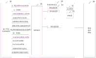
本申请详细介绍了一种基于OBD接口的支持多协议的车载诊断装置,本文中的将传统OBD产品中的MCU芯片进行变革,将原来需要外围器件实现的支持相关车载产品协议的芯片与传统的MCU的功能结合,图1为本发明一实施例提供的车载诊断装置框图。如图1所示,本实施例提供的车载诊断装置10包括:主控模块11、控制器12、选择模块13、多个协议收发器14,所述选择模块13与所述多个协议收发器中的部分或全部协议收发器相连,其中:This application introduces in detail an on-board diagnostic device that supports multi-protocol based on OBD interface. In this paper, the MCU chip in traditional OBD products is changed, and the chip that supports the related on-board product protocol that needs to be implemented by peripheral devices is replaced with the traditional one. The functions of the MCU are combined, and FIG. 1 is a block diagram of an on-board diagnostic apparatus provided by an embodiment of the present invention. As shown in FIG. 1 , the on-board
所述主控模块11用于,控制该车载诊断装置的其他模块,以及,基于选中的协议收发器及对应管脚进行数据收发;The
所述控制器12用于,接收外部控制信号,根据所述外部控制信号控制选择模块;The
所述选择模块13用于,根据所述控制器的控制,在不同的协议收发器及管脚中切换;每个协议收发器及相应的管脚支持一种OBD协议,从而可以实现支持多种OBD协议;主要为满足OBD支持的多种协议进行切换,从而达到一个设备可以匹配多个车型的目的;The
所述协议收发器14用于,实现所支持的协议的数据收发。The
该车载诊断装置可连接接口保护及转换模块20和蜂窝通讯模块30。其中接口保护及转换模块包括多个pin(管脚)。pin1(管脚1)为复用KL15/J2411/iCAN-H信号,pin2为J1850+信号,pin3为信号,pin4为KL31地信号,pin5为信号地信号,pin6为ISO15765CAN-H信号,pin7为复用ISO9141/ISO14230K信号,pin8为复用KL15/K_Line2/iCAN-L1信号,pin9为复用TD/ALDL/iCAN-L2信号,pin10为J1850-信号,pin11为复用oCAN-L/DCL-/CCD-信号,pin12为复用cCAN-H/DIC信号,pin13为复用cCAN-L/PCM信号,pin14为ISO15765CAN-L信号,pin15为复用ISO9141/ISO14230L信号,pin16为KL30电信号。The on-board diagnostic device can be connected to the interface protection and
本实施例提供的方案,通过控制器及选择模块对不同协议的收发器进行切换,能支持多种OBD标准协议,支持多种车型的通讯。相比相关技术中使用MCU和外围支持支持车载相关协议的芯片,该车载诊断装置将各协议收发器与MCU集成在一起,比传统OBD尺寸可以更小,也解决了原有不同芯片之间通讯可能出现的相关故障,性能更稳定,产品可靠性大大提高。The solution provided by this embodiment switches transceivers of different protocols through the controller and the selection module, which can support multiple OBD standard protocols and support the communication of multiple vehicle types. Compared with the related technologies that use MCU and peripheral support chips that support on-board related protocols, the on-board diagnostic device integrates each protocol transceiver and MCU, which can be smaller than the traditional OBD, and also solves the problem of communication between the original different chips. Possible related faults, the performance is more stable, and the product reliability is greatly improved.
在一实施例中,所述车载诊断装置封装为单芯片。单芯片可以用FPGA(Field-Programmable Gate Array,现场可编程门阵列)或CPLD(Complex Programmable LogicDevice,复杂可编程逻辑器件)等方式实现,成本可以根据需求采用多种方式进行优化,满足不同成本需求。选择模块可以使用开关等多种方式实现,因此该单模块封装和内部逻辑多变,并且可以根据不同产品需求定制,灵活多样。本实施例提供的方案,用单芯片方式实现车载诊断装置,该单芯片使得MCU芯片能够集运算、控制、协议支持、通讯等功能于一体,在增加了MCU芯片尺寸的同时也减少了外围器件,因此总体上是减小整版布局面积,由于将协议芯片的集成,也解决了原有不同芯片之间通讯可能出现的相关故障,产品可靠性大大提高。In one embodiment, the on-board diagnostic device is packaged as a single chip. A single chip can be realized by FPGA (Field-Programmable Gate Array, Field Programmable Gate Array) or CPLD (Complex Programmable Logic Device, Complex Programmable Logic Device). . The selection module can be implemented in various ways such as switches, so the single-module package and internal logic are changeable, and can be customized according to different product requirements, which is flexible and diverse. The solution provided in this embodiment uses a single chip to realize the on-board diagnostic device. The single chip enables the MCU chip to integrate functions such as operation, control, protocol support, and communication, and increases the size of the MCU chip while reducing the number of peripheral devices. Therefore, the overall layout area is reduced. Due to the integration of the protocol chip, the related failures that may occur in the communication between the original different chips are also solved, and the product reliability is greatly improved.
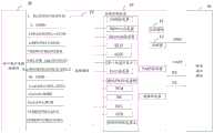
如图2所示,所述多个协议收发器可以包括下述各收发器任意组合:J1850收发器,ISO9141收发器,ISO14230收发器,KL15(点火信号),ALDL,TD(转速计显示),J2411收发器,ISO15765收发器辅,PCM,DIC,DCL,CCD,ISO15765收发器主。其中:As shown in FIG. 2, the plurality of protocol transceivers may include any combination of the following transceivers: J1850 transceiver, ISO9141 transceiver, ISO14230 transceiver, KL15 (ignition signal), ALDL, TD (tachometer display), J2411 transceiver, ISO15765 transceiver auxiliary, PCM, DIC, DCL, CCD, ISO15765 transceiver master. in:
J1850收发器可以接收和发送支持J1850协议的信号;The J1850 transceiver can receive and transmit signals that support the J1850 protocol;
ISO9141收发器可以接收和发送支持ISO9141协议的信号;ISO9141 transceiver can receive and transmit signals supporting ISO9141 protocol;
ISO14230收发器可以接收和发送支持ISO14230协议的信号;The ISO14230 transceiver can receive and transmit signals supporting the ISO14230 protocol;
KL15可以接收和发送汽车标准定义的汽车点火信号;KL15 can receive and send car ignition signals defined by car standards;
ALDL可以接收和发送基于ALDL协议的信号;ALDL协议是通用汽车实现外部设备与电控单元之间的通讯的一种协议;ALDL can receive and send signals based on ALDL protocol; ALDL protocol is a protocol for GM to realize communication between external equipment and electronic control unit;
TD可以接收和发送转速计显示信号;TD can receive and send tachometer display signal;
J2411收发器可以接收和发送单路CAN(Controller Area Network,控制器局域网络)信号;The J2411 transceiver can receive and transmit single-channel CAN (Controller Area Network) signals;
ISO15765收发器辅可以接收和发送多路CAN信号;ISO15765 transceiver can receive and transmit multiple CAN signals;
PCM可以接收和发送汽车标准中定义的音频信号;PCM can receive and transmit audio signals as defined in automotive standards;
ISO15765收发器主可以接收和发送主CAN信号。The ISO15765 transceiver master can receive and transmit master CAN signals.
其中,控制器基于GPIO(General-Purpose IO,通用输入输出)信号控制。The controller is controlled based on a GPIO (General-Purpose IO, general-purpose input and output) signal.
需要说明的是,所述车载诊断装置还包括UART(Universal AsynchronousReceiver/Transmitter,通用异步收发器)控制器和数据收发器,所述UART控制器用于接收和发送UART串口信号;数据收发器主要接收和发送所有该单芯片中的数据,此外,还包含其他的保证该单芯片能正常工作的供电,存储,控制和运算单元。It should be noted that the on-board diagnostic device further includes a UART (Universal Asynchronous Receiver/Transmitter, Universal Asynchronous Receiver/Transmitter) controller and a data transceiver, the UART controller is used to receive and send UART serial signals; the data transceiver mainly receives and transmits Send all the data in the single chip, in addition, it also contains other power supply, storage, control and operation units to ensure that the single chip can work normally.
ISO15765收发器辅可以设计一个,用多个开关进行切换;在另一实施例中,如果从响应时间和便捷性考虑,可以设计4个ISO15765收发器辅,这样一一对应连接,更方便。One ISO15765 transceiver can be designed to be switched by multiple switches; in another embodiment, if the response time and convenience are considered, four ISO15765 transceivers can be designed, so that one-to-one connection is more convenient.
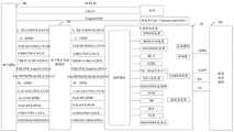
图3为车载诊断装置的一具体实施例。如图3所示,所述选择模块包括多个开关,开关2T1,开关1T4_1,开关1T4_2,开关1T4_3,开关1T4_4,开关1T4_5,开关1T2_1,开关1T2_2,开关4T1_1CNL-L,开关4T1_2CAN-H,其中,开关2T1一侧连接pin7和pin9,另一侧连接ISO9141收发器,ISO14230收发器,开关1T4_1一侧连接pin8,另一侧连接开关4T1_1CAN-L、KL15,ISO9141收发器,ISO14230收发器;开关1T4_2一侧连接pin9,另一侧连接ALDL和TD和开关4T1_1CAN-L;开关1T4_3一侧连接pin1,另一侧连接KL15,J2411收发器和开关4T1_2CAN-H;开关1T2_1一侧连接pin13,另一侧连接开关4T1_1CAN-L,PCM;开关1T2_2一侧连接pin12,另一侧连接开关4T1_2CAN-H,DIC;开关1T4_4一侧连接pin11,另一侧连接4T1_1CAN-L,DCL,CCD;开关1T4_5一侧连接pin3,另一侧连接4T1_2CAN-H,DCL,CCD。从图3中可以看出,经过接口保护及转换模块20之后的13个信号线全部接入车载诊断装置10中,pin2,pin10为J1850协议专用管脚,因此直接接入车载诊断装置的J1850收发器中,pin6,pin14为ISO15765主CAN信号专用管脚,因此直接接入车载诊断装置的ISO15765收发器中,这2组信号不通过选择模块进行切换。pin7和pin9功能定义是一样的,但是不同车厂使用的管脚不同,因此在本实施例中,在选择模块中有一个2T1开关,用来对pin7和pin9信号进行切换。同样的,因该单芯片支持多个CAN协议,因此在选择模块中设置有多个1T4(1T4_1至1T4_5),1T2(1T2_1和1T2_2)和4T1(4T1_1CAN-L和4T1_2CAN-H)的开关对多个CAN协议进行切换。FIG. 3 is a specific embodiment of an on-board diagnostic device. As shown in FIG. 3 , the selection module includes a plurality of switches, switch 2T1, switch 1T4_1, switch 1T4_2, switch 1T4_3, switch 1T4_4, switch 1T4_5, switch 1T2_1, switch 1T2_2, switch 4T1_1CNL-L, switch 4T1_2CAN-H, wherein , one side of switch 2T1 is connected to pin7 and pin9, the other side is connected to ISO9141 transceiver, ISO14230 transceiver, one side of switch 1T4_1 is connected to pin8, the other side is connected to switch 4T1_1CAN-L, KL15, ISO9141 transceiver, ISO14230 transceiver; switch 1T4_2 One side is connected to pin9, the other side is connected to ALDL and TD and switch 4T1_1CAN-L; one side of switch 1T4_3 is connected to pin1, the other side is connected to KL15, J2411 transceiver and switch 4T1_2CAN-H; one side of switch 1T2_1 is connected to pin13, the other side Connect switch 4T1_1CAN-L, PCM; one side of switch 1T2_2 is connected to pin12, the other side is connected to switch 4T1_2CAN-H, DIC; one side of switch 1T4_4 is connected to pin11, the other side is connected to 4T1_1CAN-L, DCL, CCD; one side of switch 1T4_5 is connected pin3, the other side is connected to 4T1_2CAN-H, DCL, CCD. It can be seen from Figure 3 that the 13 signal lines after the interface protection and
如图3所示,所述控制器可包括第一控制器,所述控制器包括第一控制器,所述第一控制器(或称模式控制器)用于,接收第零控制信号(MODE_0)、第一控制信号(MODE_1)、第二控制信号(MODE_2)以及第三控制信号(MODE_L),根据所述第零控制信号、所述第一控制信号、所述第二控制信号以及所述第三控制信号控制所述选择模块在支持单线ISO9141协议、支持双线ISO9141协议、支持单线ISO14230协议、支持双线ISO14230协议的协议收发器及管脚中切换。具体可参考下表1。As shown in FIG. 3 , the controller may include a first controller, and the controller includes a first controller, and the first controller (or mode controller) is configured to receive the zeroth control signal (MODE_0 ), a first control signal (MODE_1), a second control signal (MODE_2) and a third control signal (MODE_L), according to the zeroth control signal, the first control signal, the second control signal and the The third control signal controls the selection module to switch among protocol transceivers and pins supporting single-wire ISO9141 protocol, dual-wire ISO9141 protocol, single-wire ISO14230 protocol, and dual-wire ISO14230 protocol. For details, please refer to Table 1 below.
在一实施例中,所述控制器包括:第二控制器(或称辅CAN控制器),所述第二控制器用于,接收第四控制信号(CAN_MODE_0)、第五控制信号(CAN_MODE_1)、第六控制信号(CAN_MODE_2),根据所述第四控制信号、第五控制信号和第六控制信号控制所述选择模块在J2411协议、不同管脚的ISO15765协议对应的协议收发器及管脚中切换。具体可参考下表2。In one embodiment, the controller includes: a second controller (or an auxiliary CAN controller), the second controller is configured to receive a fourth control signal (CAN_MODE_0), a fifth control signal (CAN_MODE_1), The sixth control signal (CAN_MODE_2), according to the fourth control signal, the fifth control signal and the sixth control signal, control the selection module to switch among the protocol transceivers and pins corresponding to the J2411 protocol, the ISO15765 protocol of different pins . For details, please refer to Table 2 below.
在一实施例中,所述控制器包括第三控制器,所述第三控制器用于,接收第七控制信号、第八控制信号和第九控制信号,根据所述第七控制信号、第八控制信号和第九控制信号控制所述选择模块在基于不同管脚的支持KL15信号的收发器、支持TD信号的收发器、支持ALDL信号的收发器、支持DCL信号的收发器、支持CCD信号的收发器中切换。In an embodiment, the controller includes a third controller, and the third controller is configured to receive a seventh control signal, an eighth control signal, and a ninth control signal, according to the seventh control signal, the eighth control signal, and the ninth control signal. The control signal and the ninth control signal control the selection module in different pin-based transceivers supporting KL15 signals, transceivers supporting TD signals, transceivers supporting ALDL signals, transceivers supporting DCL signals, and transceivers supporting CCD signals. Transceiver switching.
MODE_0,MODE_1,MODE_2,MODE_L满足如下表格:MODE_0, MODE_1, MODE_2, MODE_L satisfy the following table:
表1 MODE_0,MODE_1,MODE_2,MODE_L真值表Table 1 MODE_0, MODE_1, MODE_2, MODE_L truth table


本表中,因为车载产品中,有些车机是单K线通讯,有些车机是K线,L线双路通讯,运用上表1进行判定。当蜂窝通讯模块将模式控制器信号MODE_0,MODE_1,MODE_2,MODE_L同时为低时,则2T1开关打开,该单芯片通过pin7,pin15向车机发送支持ISO9141协议的K线,L线双线数据信号,并且等待预设时间(具体时长根据需要设定),如果车机反馈数据,则认为车机支持通过pin7和pin15进行ISO9141协议相关K线,L线双线数据业务,如果车机无反馈,则认为该车机的pin7和pin15不支持支持ISO9141双线数据业务;将MODE_0,MODE_1,MODE_2置为低,MODE_L置为高,则该单芯片通过pin7向车机发送支持ISO9141协议的单K线数据,并且等待一段时间,如果车机反馈数据,则认为车机支持通过pin7进行ISO9141协议相关单K线数据业务,如果车机仍无反馈,则认为该车机的pin7不支持支持ISO9141协议,按照上述表1继续往下进行。以此类推,直到某一种模式判断成功后,则认为该车机有K/L单/双线通讯需求,确定对应pin脚和支持的协议后,该车机就通过DATA_RX,DATA_TX与蜂窝通讯模块进行数据收发业务。In this table, because some of the vehicle-mounted products have single K-line communication, and some vehicles have K-line and L-line dual-channel communication, the above table 1 is used to determine. When the cellular communication module sets the mode controller signals MODE_0, MODE_1, MODE_2, and MODE_L to be low at the same time, the 2T1 switch is turned on, and the single chip sends the K line and L line two-line data signal supporting the ISO9141 protocol to the vehicle through pin7 and pin15. , and wait for the preset time (the specific duration is set according to the needs), if the car machine feeds back data, it is considered that the car machine supports the ISO9141 protocol related K-line and L-line two-line data services through pin7 and pin15, if the car machine has no feedback, Then it is considered that pin7 and pin15 of the car do not support ISO9141 dual-line data services; if MODE_0, MODE_1, MODE_2 are set to low, and MODE_L is set to high, the single chip sends a single K line that supports ISO9141 protocol to the car through pin7 data, and wait for a period of time, if the car machine feedback data, it is considered that the car machine supports the ISO9141 protocol related single K line data business through pin7, if the car machine still has no feedback, it is considered that the car machine pin7 does not support the ISO9141 protocol, Continue to proceed according to Table 1 above. And so on, until a certain mode is judged successfully, it is considered that the vehicle has K/L single/dual communication requirements. After determining the corresponding pin and the supported protocol, the vehicle communicates with the cellular through DATA_RX and DATA_TX. The module performs data sending and receiving services.
按照表1全部判断完成后无一种满足的情况,则MODE_0,MODE_1,MODE_2,MODE_L全部置高,表示该车机不支持ISO9141和ISO14230通讯协议。需要说明的是,全部置高仅为示例,可以根据需要置为其他值,与表1中已占用的值不同即可。另外,表1仅为示例,MODE_0,MODE_1,MODE_2,MODE_L取值与所支持的协议、所选择的pin脚的对应关系可以根据需要进行变更。According to Table 1, after all the judgments are completed, there is no satisfied situation, then MODE_0, MODE_1, MODE_2, and MODE_L are all set high, indicating that the vehicle does not support ISO9141 and ISO14230 communication protocols. It should be noted that all setting high is only an example, and can be set to other values as required, which may be different from the occupied values in Table 1. In addition, Table 1 is only an example, and the corresponding relationship between the values of MODE_0, MODE_1, MODE_2, and MODE_L, the supported protocol, and the selected pin can be changed as required.
在单芯片与蜂窝通讯模块的通讯中增加辅CAN控制器,其之间的通讯信号CAN_MODE_0,CAN_MODE_1,CAN_MODE_2对不同CAN信号进行选择,同样CAN_MODE_0,CAN_MODE_1,CAN_MODE_2满足如下真值表:A secondary CAN controller is added to the communication between the single chip and the cellular communication module, and the communication signals CAN_MODE_0, CAN_MODE_1, and CAN_MODE_2 between them select different CAN signals. Similarly, CAN_MODE_0, CAN_MODE_1, and CAN_MODE_2 satisfy the following truth table:
表2 CAN_MODE_0,CAN_MODE_1,CAN_MODE_2真值表Table 2 CAN_MODE_0, CAN_MODE_1, CAN_MODE_2 truth table

①注:pin8和pin9都可以定义为iCAN_L信号,不同车厂定义不同,因此需要进行模式判定。①Note: Both pin8 and pin9 can be defined as iCAN_L signals. Different car manufacturers have different definitions, so mode determination is required.
上表中,当蜂窝通讯模块将CAN_MODE_0,CAN_MODE_1,CAN_MODE_2均置为低电平信号时,模拟开关中4T1_1与1T4_3开关打开,因此单芯片通过pin1向车机发送支持J2411协议的信号,并等待车机反馈,如果预设时间内车机有反馈,则蜂窝通讯模块通过单芯片与车机通讯,如果预设时间内车机无反馈,则认为该车机不支持J2411协议;然后蜂窝通讯模块控制CAN_MODE_0,CAN_MODE_2为低,CAN_MODE_1为高,则开关1T4_1,1T4_3,4T1_1,4T1_2开关同时打开,单芯片通过pin1,pin8,向车机发送ISO15765协议的数据,并等待车机反馈,如果预设时间内车机有反馈,则认为车机pin1,pin8支持ISO15765协议,则模块通过单芯片与车机进行通讯,如果预设时间内车机无反馈,则继续按照表2重复上一步进行判断。In the above table, when the cellular communication module sets CAN_MODE_0, CAN_MODE_1, and CAN_MODE_2 as low level signals, the switches 4T1_1 and 1T4_3 in the analog switch are turned on, so the single chip sends a signal supporting the J2411 protocol to the vehicle through pin1, and waits for the vehicle If there is feedback from the vehicle and the vehicle within the preset time, the cellular communication module communicates with the vehicle through a single chip. If there is no feedback from the vehicle within the preset time, it is considered that the vehicle does not support the J2411 protocol; then the cellular communication module controls CAN_MODE_0, CAN_MODE_2 is low, CAN_MODE_1 is high, the switches 1T4_1, 1T4_3, 4T1_1, 4T1_2 are turned on at the same time, the single chip sends the ISO15765 protocol data to the vehicle through pin1, pin8, and waits for the feedback from the vehicle. If the preset time If there is feedback from the vehicle, it is considered that pin1 and pin8 of the vehicle support the ISO15765 protocol, and the module communicates with the vehicle through a single chip. If there is no feedback from the vehicle within the preset time, continue to repeat the previous step according to Table 2.
同样的,该辅CAN收发器存在全部判定完成后没有一个满足,则蜂窝通讯模块将CAN_MODE_0,CAN_MODE_1,CAN_MODE_2全部置高,表示该车型无辅CAN需求。需要说明的是,全部置高仅为示例,可以根据需要置为其他值,与表2中已占用的值不同即可。另外,表2仅为示例,CAN_MODE_0,CAN_MODE_1,CAN_MODE_2取值与所支持的协议、所选择的pin脚的对应关系可以根据需要进行变更。Similarly, if none of the auxiliary CAN transceivers are satisfied after all the judgments are completed, the cellular communication module will set all CAN_MODE_0, CAN_MODE_1, and CAN_MODE_2 high, indicating that the model has no auxiliary CAN requirements. It should be noted that all setting heights are only examples, and can be set to other values as required, which may be different from the occupied values in Table 2. In addition, Table 2 is only an example, and the corresponding relationship between the values of CAN_MODE_0, CAN_MODE_1, and CAN_MODE_2, supported protocols, and selected pins can be changed as required.
本发明实施例中,通过单芯片中的选择模块,对不同协议的收发器进行切换,并通过控制器对不同协议的收发器进行控制,从而达到自动适配多种OBD标准协议,支持多种车型的通讯。In the embodiment of the present invention, the transceivers of different protocols are switched through the selection module in a single chip, and the transceivers of different protocols are controlled by the controller, so as to automatically adapt to multiple OBD standard protocols and support multiple Model communications.
如图4所示,本发明一实施例提供一种车载诊断系统,包括:车载诊断装置10,还包括,接口模块40、接口保护及转换模块20、蜂窝通讯模块30,所述接口模块40用于连接外部车机、所述接口保护及转换模块20连接所述接口模块40和所述车载诊断装置10,所述车载诊断装置10连接所述蜂窝通讯模块30,其中:As shown in FIG. 4 , an embodiment of the present invention provides an on-board diagnostic system, which includes: an on-board
所述接口模块40用于,连接车机的车载诊断系统接口;接口模块比如为pin16J1962连接器,为标准OBD接口。The
所述接口保护及转换模块20用于,对接口模块40和车载诊断装置10之间的信号进行转换以匹配;因汽车使用的电平一般为12V或者24V,因此OBD接口接收到的信号高电平也为对应的12V/24V信号,但是车载诊断装置10一般电平较低,因此在接口模块40和车载诊断装置10中间增加一个器件,从而匹配两边的电平。该器件可以实现静电保护、滤波和电平转换等,经过电平转换的信号接入车载诊断装置10中。所述接口保护及转换模块20可进行ESD(electro-static discharge,静电放电)/EMI((Electromagnetic Interference,电磁干扰)防护,以及,12V/24V电平转换。The interface protection and
所述蜂窝通讯模块30用于,实现所述车载诊断装置10与外部网络的通信,外部网络可包括车机网络,以及对车机进行管控的管控中心网络。The
车载诊断系统接口模块的pin16和pin4与电源连接,pin5连接功能单元地。Pin16 and pin4 of the on-board diagnostic system interface module are connected to the power supply, and pin5 is connected to the functional unit ground.
在一实施例中,所述蜂窝通讯模块30还用于,发送控制信号至所述车载诊断装置10;In one embodiment, the
所述车载诊断装置10还用于,根据所述控制信号,选中对应的协议收发器以及管脚,基于所选管脚进行所选的协议收发器对应的协议数据的发送,根据是否接收到所述待测车机的反馈确定所述待测车机是否支持基于所选管脚及所选的协议收发器进行数据收发,以及,基于所述待测车机所支持的协议收发器及相应管脚与所述待测车机通信。The on-board
本发明一实施例提供一种检测方法,如图5所示,应用于任一实施例所述的车载诊断装置,包括:An embodiment of the present invention provides a detection method, as shown in FIG. 5 , which is applied to the on-board diagnostic apparatus described in any embodiment, including:
步骤501,接收控制信号,选中对应的协议收发器以及管脚;
步骤502,基于所选管脚进行所选的协议收发器对应的协议数据的发送,根据是否接收到所述待测车机的反馈确定所述待测车机是否支持基于所选管脚及所选的协议收发器进行数据收发。
在一实施例中,所述步骤502中,根据是否接收到所述待测车机的反馈确定所述待测车机是否支持基于所选管脚及所选的协议收发器进行数据收发包括:In one embodiment, in the
当在预设时间内接收到所述待测车机的反馈时,判断所述待测车机支持基于所选管脚及所选的协议收发器进行数据收发;When the feedback of the vehicle under test is received within a preset time, it is determined that the vehicle under test supports data transmission and reception based on the selected pin and the selected protocol transceiver;
当在预设时间内未接收到所述待测车机的反馈时,判断所述待测车机不支持基于所选管脚及所选的协议收发器进行数据收发。When no feedback from the vehicle under test is received within a preset time, it is determined that the vehicle under test does not support data transmission and reception based on the selected pin and the selected protocol transceiver.
图6为本发明一实施例提供的K/L线单/双数据通讯判断流程图。如图6所示,包括:FIG. 6 is a flow chart of determining a K/L line single/dual data communication according to an embodiment of the present invention. As shown in Figure 6, including:
步骤601,将MODE_0,MODE_1,MODE_2,MODE_L均设置为低电平,通过pin7,pin15向车机发送支持ISO9141协议的K线,L线双线数据信号;Step 601: Set MODE_0, MODE_1, MODE_2, and MODE_L to low level, and send the K-line and L-line two-line data signals supporting the ISO9141 protocol to the vehicle through pin7 and pin15;
步骤602,等待预设时间(具体时长根据需要设定),判断在预设时间内是否接受到车机的反馈,如果接收到车机的反馈数据,执行步骤603,如果未接收到车机的反馈,执行步骤604;
步骤603,车机支持通过pin7和pin15进行ISO9141协议相关K线,L线双线数据业务,结束;
步骤604,认为该车机的pin7和pin15不支持支持ISO9141双线数据业务;
步骤605,将MODE_0,MODE_1,MODE_2置为低电平,MODE_L置为高电平,通过pin7向车机发送支持ISO9141协议的单K线数据信号;Step 605: Set MODE_0, MODE_1, MODE_2 to low level, and MODE_L to high level, and send a single K-line data signal supporting ISO9141 protocol to the vehicle through pin7;
步骤606,等待预设时间(具体时长根据需要设定),判断在预设时间内是否接受到车机的反馈,如果接收到车机的反馈数据,执行步骤607,如果未接收到车机的反馈,执行步骤608;Step 606, wait for a preset time (the specific duration is set according to needs), and determine whether the feedback from the vehicle is received within the preset time. If the feedback data from the vehicle is received, go to step 607. feedback, go to step 608;
步骤607,车机支持通过pin7进行ISO9141协议相关单K线数据业务,结束;
步骤608,认为该车机的pin7不支持ISO9141数据业务;
步骤609,将MODE_0,MODE_1,MODE_L置为低电平,MODE_2置为高电平,通过pin9,pin15向车机发送支持ISO9141协议的K线,L线双线数据信号;Step 609: Set MODE_0, MODE_1, and MODE_L to low level, and MODE_2 to high level, and send K line and L line two-line data signals supporting ISO9141 protocol to the vehicle through pin9 and pin15;
步骤610,等待预设时间(具体时长根据需要设定),判断在预设时间内是否接受到车机的反馈,如果接收到车机的反馈数据,执行步骤611,如果未接收到车机的反馈,执行步骤612;
步骤611,判定车机支持通过pin9,pin15进行ISO9141协议相关K线,L线双线数据业务,结束;In
步骤612,认为该车机不支持通过pin9,pin15进行ISO9141协议相关K线,L线双线数据业务;
步骤613,将MODE_0,MODE_1置为低电平,MODE_2,MODE_L置为高电平,通过pin9向车机发送支持ISO9141协议的单K线数据信号;Step 613: Set MODE_0 and MODE_1 to low level, MODE_2 and MODE_L to high level, and send a single K-line data signal supporting ISO9141 protocol to the vehicle through pin9;
步骤614,等待预设时间(具体时长根据需要设定),判断在预设时间内是否接受到车机的反馈,如果接收到车机的反馈数据,执行步骤515,如果未接收到车机的反馈,执行步骤516;
步骤615,判定车机支持通过pin9进行ISO9141协议相关单K线数据业务,结束;
步骤616,认为该车机不支持通过pin9进行ISO9141协议相关单K线数据业务;
步骤617,将MODE_0,MODE_2,MODE_L置为低电平,MODE_1置为高电平,通过pin7、pin15向车机发送支持ISO14230协议的K线,L线双线数据信号;Step 617: Set MODE_0, MODE_2, and MODE_L to low level, and MODE_1 to high level, and send two-line data signals of K line and L line supporting ISO14230 protocol to the vehicle through pin7 and pin15;
步骤618,等待预设时间(具体时长根据需要设定),判断在预设时间内是否接受到车机的反馈,如果接收到车机的反馈数据,执行步骤619,如果未接收到车机的反馈,执行步骤620;
步骤619,判定车机支持通过pin7,pin15进行ISO14230协议相关K线,L线双线数据业务,结束;In
步骤620,认为该车机不支持通过pin7,pin15进行ISO14230协议相关K线,L线双线数据业务;
步骤621,将MODE_0,MODE_2置为低电平,MODE_1,MODE_L置为高电平,通过pin7向车机发送支持ISO14230协议的单K线数据信号;Step 621: Set MODE_0 and MODE_2 to low level, MODE_1 and MODE_L to high level, and send a single K-line data signal supporting ISO14230 protocol to the vehicle through pin7;
步骤622,等待预设时间(具体时长根据需要设定),判断在预设时间内是否接受到车机的反馈,如果接收到车机的反馈数据,执行步骤623,如果未接收到车机的反馈,执行步骤624;Step 622, wait for a preset time (the specific duration is set according to needs), and determine whether the feedback from the vehicle is received within the preset time. If the feedback data from the vehicle is received, go to step 623. feedback, go to step 624;
步骤623,判定车机支持通过pin7进行ISO14230协议相关单K线数据业务,结束;In
步骤624,认为该车机不支持通过pin7进行ISO14230协议相关单K线数据业务;
步骤625,将MODE_0,MODE_L置为低电平,MODE_1,MODE_2置为高电平,通过pin9,pin15向车机发送支持ISO14230协议的K线,L线双线数据信号;Step 625: Set MODE_0 and MODE_L to low level, MODE_1 and MODE_2 to high level, and send the K line and L line two-line data signal supporting ISO14230 protocol to the vehicle through pin9 and pin15;
步骤626,等待预设时间(具体时长根据需要设定),判断在预设时间内是否接受到车机的反馈,如果接收到车机的反馈数据,执行步骤627,如果未接收到车机的反馈,执行步骤628;
步骤627,判定车机支持通过pin9、pin15进行ISO14230协议相关K线,L线双线数据业务,结束;Step 627: It is determined that the vehicle and the machine support the ISO14230 protocol-related K-line and L-line dual-line data services through pin9 and pin15, and the process ends;
步骤628,认为该车机不支持通过pin9、pin15进行ISO14230协议相关K线,L线双线数据业务;
步骤629,将MODE_0置为低电平,MODE_1,MODE_2,MODE_L置为高电平,通过pin9向车机发送支持ISO14230协议的单K线数据信号;Step 629: Set MODE_0 to low level, MODE_1, MODE_2, and MODE_L to high level, and send a single K-line data signal supporting ISO14230 protocol to the vehicle through pin9;
步骤630,等待预设时间(具体时长根据需要设定),判断在预设时间内是否接受到车机的反馈,如果接收到车机的反馈数据,执行步骤631,如果未接收到车机的反馈,执行步骤632;Step 630, wait for a preset time (the specific duration can be set according to needs), and determine whether the feedback from the vehicle is received within the preset time. If the feedback data from the vehicle is received, go to step 631. feedback, go to step 632;
步骤631,判定车机支持通过pin9进行ISO14230协议相关单K线数据业务,结束;
步骤632,认为该车机不支持通过pin9进行ISO14230协议相关单K线数据业务;
步骤633,将MODE_1,MODE_2,MODE_L均设置为低电平,MODE_0置为高电平,通过pin8,pin15向车机发送支持ISO9141协议的K线,L线双线数据信号;Step 633: Set MODE_1, MODE_2, and MODE_L to low level, and MODE_0 to high level, and send two-line data signals of K line and L line supporting ISO9141 protocol to the vehicle through pin8 and pin15;
步骤634,等待预设时间(具体时长根据需要设定),判断在预设时间内是否接受到车机的反馈,如果接收到车机的反馈数据,执行步骤635,如果未接收到车机的反馈,执行步骤636;
步骤635,车机支持通过pin8和pin15进行ISO9141协议相关K线,L线双线数据业务,结束;
步骤636,认为该车机的pin8和pin15不支持支持ISO9141双线数据业务;
步骤637,将MODE_1,MODE_2设置为低电平,MODE_0,MODE_L置为高电平,通过pin8向车机发送支持ISO9141协议的单K线数据信号;Step 637: Set MODE_1 and MODE_2 to low level, MODE_0 and MODE_L to high level, and send a single K-line data signal supporting ISO9141 protocol to the vehicle through pin8;
步骤638,等待预设时间(具体时长根据需要设定),判断在预设时间内是否接受到车机的反馈,如果接收到车机的反馈数据,执行步骤639,如果未接收到车机的反馈,执行步骤640;Step 638, wait for a preset time (the specific duration is set according to needs), and determine whether the feedback from the vehicle is received within the preset time. If the feedback data from the vehicle is received, go to step 639. feedback, go to step 640;
步骤639,车机支持通过pin8进行ISO9141协议相关单K线数据业务,结束;
步骤640,认为该车机的pin8不支持支持ISO9141数据业务;
步骤641,将MODE_1,MODE_L置为低电平,MODE_0,MODE_2置为高电平,通过pin8,pin15向车机发送支持ISO14230协议的K线,L线双线数据信号;
步骤642,等待预设时间(具体时长根据需要设定),判断在预设时间内是否接受到车机的反馈,如果接收到车机的反馈数据,执行步骤643,如果未接收到车机的反馈,执行步骤644;Step 642, wait for a preset time (the specific duration is set according to needs), and determine whether the feedback from the vehicle is received within the preset time. If the feedback data from the vehicle is received, go to step 643. feedback, go to step 644;
步骤643,判定车机支持通过pin8、pin15进行ISO14230协议相关K线,L线双线数据业务,结束;In
步骤644,认为该车机不支持通过pin8、pin15进行ISO14230协议相关K线,L线双线数据业务;
步骤645,将MODE_1置为低电平,MODE_0,MODE_2,MODE_L置为高电平,通过pin8向车机发送支持ISO14230协议的单K线数据信号;Step 645: Set MODE_1 to a low level, MODE_0, MODE_2, and MODE_L to a high level, and send a single K-line data signal supporting the ISO14230 protocol to the vehicle through pin8;
步骤646,等待预设时间(具体时长根据需要设定),判断在预设时间内是否接受到车机的反馈,如果接收到车机的反馈数据,执行步骤647,如果未接收到车机的反馈,执行步骤648;
步骤647,判定车机支持通过pin8进行ISO14230协议相关单K线数据业务,结束;In
步骤648,认为该车机不支持通过pin8进行ISO14230协议相关单K线数据业务;
步骤649,将MODE_0,MODE_1,MODE_2,MODE_L置为高电平,表示该车机不支持ISO9141和ISO14230协议。Step 649: Set MODE_0, MODE_1, MODE_2, and MODE_L to a high level, indicating that the vehicle does not support the ISO9141 and ISO14230 protocols.
图7为本发明一实施例提供的辅CAN选择判断流程图。如图7所示,包括:FIG. 7 is a flowchart for determining the selection of an auxiliary CAN provided by an embodiment of the present invention. As shown in Figure 7, including:
步骤701,将CAN_MODE_0,CAN_MODE_1,CAN_MODE_2均设置为低电平,通过pin1向车机发送支持J2411协议的信号;Step 701: Set CAN_MODE_0, CAN_MODE_1, and CAN_MODE_2 to low level, and send a signal supporting the J2411 protocol to the vehicle through pin1;
步骤702,等待预设时间(具体时长根据需要设定),判断在预设时间内是否接受到车机的反馈,如果接收到车机的反馈数据,执行步骤703,如果未接收到车机的反馈,执行步骤704;
步骤703,判定车机支持通过pin1进行J2411协议业务,支持辅助单CAN通讯,结束;In
步骤704,判定该车机不支持通过pin1进行J2411协议业务;
步骤705,将CAN_MODE_0,CAN_MODE_2设置为低电平,CAN_MODE_1设置为高电平,通过pin1、pin8向车机发送支持ISO15765协议的信号;Step 705: Set CAN_MODE_0 and CAN_MODE_2 to low level and CAN_MODE_1 to high level, and send a signal supporting the ISO15765 protocol to the vehicle through pin1 and pin8;
步骤706,等待预设时间(具体时长根据需要设定),判断在预设时间内是否接受到车机的反馈,如果接收到车机的反馈数据,执行步骤707,如果未接收到车机的反馈,执行步骤708;
步骤707,判定车机支持通过pin1,pin8进行ISO15765协议辅助双线CAN通讯,结束;In
步骤708,判定该车机不支持通过pin1,pin8进行ISO15765协议辅助双线CAN通讯;
步骤709,将CAN_MODE_0设置为低电平,CAN_MODE_1,CAN_MODE_2设置为高电平,通过pin1、pin9向车机发送支持ISO15765协议的信号;Step 709: Set CAN_MODE_0 to low level, CAN_MODE_1 and CAN_MODE_2 to high level, and send a signal supporting the ISO15765 protocol to the vehicle through pin1 and pin9;
步骤710,等待预设时间(具体时长根据需要设定),判断在预设时间内是否接受到车机的反馈,如果接收到车机的反馈数据,执行步骤711,如果未接收到车机的反馈,执行步骤712;
步骤711,判定车机支持通过pin1,pin9进行ISO15765协议辅助双线CAN通讯,结束;In
步骤712,判定该车机不支持通过pin1,pin9进行ISO15765协议辅助双线CAN通讯;
步骤713,将CAN_MODE_0设置为高电平,CAN_MODE_1,CAN_MODE_2设置为低电平,通过pin12、pin13向车机发送支持ISO15765协议的信号;Step 713: Set CAN_MODE_0 to high level, CAN_MODE_1 and CAN_MODE_2 to low level, and send a signal supporting the ISO15765 protocol to the vehicle through pin12 and pin13;
步骤714,等待预设时间(具体时长根据需要设定),判断在预设时间内是否接受到车机的反馈,如果接收到车机的反馈数据,执行步骤715,如果未接收到车机的反馈,执行步骤716;
步骤715,判定车机支持通过pin12,pin13进行ISO15765协议辅助双线CAN通讯,结束;In
步骤716,判定该车机不支持通过pin12,pin13进行ISO15765协议辅助双线CAN通讯;
步骤717,将CAN_MODE_0,CAN_MODE_2设置为高电平,CAN_MODE_1设置为低电平,通过pin3、pin11向车机发送支持ISO15765协议的信号;Step 717: Set CAN_MODE_0 and CAN_MODE_2 to high level and CAN_MODE_1 to low level, and send a signal supporting the ISO15765 protocol to the vehicle through pin3 and pin11;
步骤718,等待预设时间(具体时长根据需要设定),判断在预设时间内是否接受到车机的反馈,如果接收到车机的反馈数据,执行步骤719,如果未接收到车机的反馈,执行步骤720;
步骤719,判定车机支持通过pin3,pin11进行ISO15765协议辅助双线CAN通讯,结束;
步骤720,判定该车机不支持通过pin3,pin11进行ISO15765协议辅助双线CAN通讯;
步骤721,将CAN_MODE_0,CAN_MODE_1,CAN_MODE_2均设置为高电平,表示车机不支持辅助CAN通讯。
在一实施例中,可以对单芯片进行一个整体判定,如图8所示,包括:In one embodiment, an overall determination can be performed on a single chip, as shown in FIG. 8 , including:
步骤801:蜂窝通讯模块按照表1控制模式控制器对K/L线单/双线进行判定后,读取判定后控制信号的电平;Step 801: After the cellular communication module judges the single/double line of the K/L line according to the control mode controller in Table 1, reads the level of the control signal after the judgment;
步骤802:判断MODE_0电平是否为高,如果为低,结束,如果为高则执行步骤803;Step 802: Determine whether the MODE_0 level is high, if it is low, end, if it is high, execute
步骤803:判断MODE_1电平是否为高,如果为低,结束,如果为高则执行步骤804;Step 803: Determine whether the level of MODE_1 is high, if it is low, end, if it is high, execute
步骤804:判断MODE_2电平是否为高,如果为低,结束,如果为高则执行步骤805;Step 804: Determine whether the level of MODE_2 is high, if it is low, end, if it is high, execute
步骤805:判断MODE_L电平是否为高,如果为低,结束,如果为高则执行步骤806;Step 805: Determine whether the MODE_L level is high, if it is low, end, and if it is high, execute
步骤806:判断此车机无K/L单/双线通讯需求,即不支持ISO9141,ISO14230协议,然后执行步骤807;Step 806: It is judged that the vehicle has no K/L single/dual communication requirement, that is, it does not support ISO9141 and ISO14230 protocols, and then step 807 is executed;
步骤807:判断CAN_MODE_0电平是否为高,如果为低,结束,如果为高则执行步骤708;Step 807: Determine whether the level of CAN_MODE_0 is high, if it is low, end, if it is high, go to step 708;
步骤808:判断CAN_MODE_1电平是否为高,如果为低,结束,如果为高则执行步骤809;Step 808: Determine whether the level of CAN_MODE_1 is high, if it is low, end, if it is high, go to step 809;
步骤809:判断CAN_MODE_2电平是否为高,如果为低,结束,如果为高则执行步骤710;Step 809: determine whether the level of CAN_MODE_2 is high, if it is low, end, if it is high, execute
步骤810:判断此车机无辅CAN需求,也无K/L单/双线通讯,蜂窝通讯模块与车机按照标准接口通讯,结束。Step 810: It is judged that the vehicle-machine has no auxiliary CAN requirement and no K/L single/dual-line communication, the cellular communication module communicates with the vehicle-machine according to the standard interface, and the process ends.
下面通过一将本申请提供的装置及系统接入一具体车机说明本申请。The present application is described below by connecting the device and system provided by the present application to a specific vehicle machine.
举例如下:某车机的OBD接口信号定义如下表3:An example is as follows: The OBD interface signals of a vehicle are defined as shown in Table 3:
表3某车机OBD接口定义Table 3 Definition of OBD interface of a vehicle


当该车机接入本申请一实施例提供的单芯片OBD产品后,单芯片即开始对该车机进行检测,先将MODE_0,MODE_1,MODE_2,MODE_L全置为0,单芯片对车机通过pin7,15进行ISO9141协议的双线数据发送,然后等待车机反馈,因车机不支持ISO9141协议,因此车机无任何反馈,然后单芯片将MODE_L置高,单芯片对车机通过pin7进行ISO9141协议的单线数据发送,然后等待车机反馈,车机仍然无反馈,接着单芯片将MODE_2置为高,MODE_L置低,单芯片对车机通过pin9,15进行ISO9141协议的双线数据发送,车机无反馈,然后依次进行判定,当pin7,15进行ISO14230协议的双线数据发送,发现车机有反馈,因此单芯片判定pin7,15支持ISO14230协议双线通讯。When the vehicle is connected to the single-chip OBD product provided by an embodiment of the present application, the single-chip starts to detect the vehicle. First, MODE_0, MODE_1, MODE_2, and MODE_L are all set to 0, and the single-chip detects the vehicle. Pin7 and 15 send the two-wire data of the ISO9141 protocol, and then wait for the feedback from the vehicle. Because the vehicle does not support the ISO9141 protocol, there is no feedback from the vehicle. Then the single-chip sets MODE_L to high, and the single-chip performs ISO9141 on the vehicle through pin7. The single-line data of the protocol is sent, and then wait for the feedback from the vehicle and the vehicle. There is still no feedback from the vehicle. Then the single-chip sets MODE_2 to high and MODE_L to low. There is no feedback from the car, and then it is judged in turn. When pins 7 and 15 send the two-wire data of the ISO14230 protocol, it is found that the car has feedback, so the single chip determines that the
再接着对辅助CAN收发器支持的协议进行判定。单芯片先将CAN_MODE_0,CAN_MODE_1,CAN_MODE_2都置为0,然后通过数据口对pin1进行J2411协议的单线CAN数据发送,然后等待车机反馈,车机无反应。然后将CAN_MODE_1置为高,单芯片通过数据口1,8进行ISO15765协议的双线CAN数据发送,然后等待车机反馈,车机无反应。然后将CAN_MODE_2置为高,单芯片通过pin1,9进行ISO15765协议的双线CAN数据发送,然后等待车机反馈,车机无反应。然后将CAN_MODE_0置为高,CAN_MODE_1,CAN_MODE_2置为低,单芯片通过pin12,13进行ISO15765协议的双线CAN数据发送,然后等待车机反馈,车机无反应。再将CAN_MODE_2置为高,单芯片通过pin3,11进行ISO15765协议的双线CAN数据发送,然后等待车机反馈,车机有反馈,则单芯片判定该车机pin3,11支持ISO15765协议双线CAN数据收发。Next, the protocol supported by the auxiliary CAN transceiver is determined. The single chip first sets CAN_MODE_0, CAN_MODE_1, and CAN_MODE_2 to 0, and then sends the single-wire CAN data of the J2411 protocol to pin1 through the data port, and then waits for the feedback from the vehicle, but the vehicle does not respond. Then set CAN_MODE_1 to high, the single chip sends the two-wire CAN data of the ISO15765 protocol through the
自此单芯片对车机判定完成,然后按照对应的pin脚用相应的协议进行通讯。Since then, the single chip has completed the determination of the vehicle and the machine, and then communicates with the corresponding protocol according to the corresponding pin.
本发明至少一实施例中,将原有的MCU,车载产品支持的协议芯片,控制信号等集成,并且增加多个开关灵活切换,从而达到支持多个车型,不同协议的目的,同时可以有效的减小OBD产品的布局面积,进而减小产品尺寸。In at least one embodiment of the present invention, the original MCU, the protocol chip supported by the in-vehicle product, the control signal, etc. are integrated, and multiple switches are added for flexible switching, so as to achieve the purpose of supporting multiple models and different protocols, and at the same time, it can effectively Reduce the layout area of OBD products, thereby reducing product size.
如图9所示,本发明一实施例提供一种检测装置90,包括存储器910和处理器920,所述存储器910存储有程序,所述程序在被所述处理器920读取执行时,实现任一实施例所述的检测方法。As shown in FIG. 9 , an embodiment of the present invention provides a
如图10所示,本发明一实施例提供一种计算机可读存储介质100,所述计算机可读存储介质100存储有一个或者多个程序110,所述一个或者多个程序110可被一个或者多个处理器执行,以实现任一实施例所述的检测方法。As shown in FIG. 10, an embodiment of the present invention provides a computer-
本领域普通技术人员可以理解,上文中所公开方法中的全部或某些步骤、系统、装置中的功能模块/单元可以被实施为软件、固件、硬件及其适当的组合。在硬件实施方式中,在以上描述中提及的功能模块/单元之间的划分不一定对应于物理组件的划分;例如,一个物理组件可以具有多个功能,或者一个功能或步骤可以由若干物理组件合作执行。某些组件或所有组件可以被实施为由处理器,如数字信号处理器或微处理器执行的软件,或者被实施为硬件,或者被实施为集成电路,如专用集成电路。这样的软件可以分布在计算机可读介质上,计算机可读介质可以包括计算机存储介质(或非暂时性介质)和通信介质(或暂时性介质)。如本领域普通技术人员公知的,术语计算机存储介质包括在用于存储信息(诸如计算机可读指令、数据结构、程序模块或其他数据)的任何方法或技术中实施的易失性和非易失性、可移除和不可移除介质。计算机存储介质包括但不限于RAM、ROM、EEPROM、闪存或其他存储器技术、CD-ROM、数字多功能盘(DVD)或其他光盘存储、磁盒、磁带、磁盘存储或其他磁存储装置、或者可以用于存储期望的信息并且可以被计算机访问的任何其他的介质。此外,本领域普通技术人员公知的是,通信介质通常包含计算机可读指令、数据结构、程序模块或者诸如载波或其他传输机制之类的调制数据信号中的其他数据,并且可包括任何信息递送介质。Those of ordinary skill in the art can understand that all or some of the steps in the methods disclosed above, functional modules/units in the systems, and devices can be implemented as software, firmware, hardware, and appropriate combinations thereof. In a hardware implementation, the division between functional modules/units mentioned in the above description does not necessarily correspond to the division of physical components; for example, one physical component may have multiple functions, or one function or step may be composed of several physical components Components execute cooperatively. Some or all of the components may be implemented as software executed by a processor, such as a digital signal processor or microprocessor, or as hardware, or as an integrated circuit, such as an application specific integrated circuit. Such software may be distributed on computer-readable media, which may include computer storage media (or non-transitory media) and communication media (or transitory media). As known to those of ordinary skill in the art, the term computer storage media includes both volatile and nonvolatile implemented in any method or technology for storage of information, such as computer readable instructions, data structures, program modules or other data flexible, removable and non-removable media. Computer storage media include, but are not limited to, RAM, ROM, EEPROM, flash memory or other memory technology, CD-ROM, digital versatile disk (DVD) or other optical disk storage, magnetic cartridges, magnetic tape, magnetic disk storage or other magnetic storage devices, or may Any other medium used to store desired information and which can be accessed by a computer. In addition, communication media typically embodies computer readable instructions, data structures, program modules, or other data in a modulated data signal such as a carrier wave or other transport mechanism, and can include any information delivery media, as is well known to those of ordinary skill in the art .
Claims (10)
Priority Applications (4)
| Application Number | Priority Date | Filing Date | Title |
|---|---|---|---|
| CN201910450652.8ACN112015156A (en) | 2019-05-28 | 2019-05-28 | Vehicle-mounted diagnostic device, system, and detection method |
| EP20815583.8AEP3923103B1 (en) | 2019-05-28 | 2020-02-17 | On-board diagnostics device and system, and detection method and readable storage medium |
| US17/435,912US20220317671A1 (en) | 2019-05-28 | 2020-02-17 | On-board diagnostics device and system, and detection method and readable storage medium |
| PCT/CN2020/075596WO2020238287A1 (en) | 2019-05-28 | 2020-02-17 | On-board diagnostics device and system, and detection method and readable storage medium |
Applications Claiming Priority (1)
| Application Number | Priority Date | Filing Date | Title |
|---|---|---|---|
| CN201910450652.8ACN112015156A (en) | 2019-05-28 | 2019-05-28 | Vehicle-mounted diagnostic device, system, and detection method |
Publications (1)
| Publication Number | Publication Date |
|---|---|
| CN112015156Atrue CN112015156A (en) | 2020-12-01 |
Family
ID=73501368
Family Applications (1)
| Application Number | Title | Priority Date | Filing Date |
|---|---|---|---|
| CN201910450652.8APendingCN112015156A (en) | 2019-05-28 | 2019-05-28 | Vehicle-mounted diagnostic device, system, and detection method |
Country Status (4)
| Country | Link |
|---|---|
| US (1) | US20220317671A1 (en) |
| EP (1) | EP3923103B1 (en) |
| CN (1) | CN112015156A (en) |
| WO (1) | WO2020238287A1 (en) |
Cited By (1)
| Publication number | Priority date | Publication date | Assignee | Title |
|---|---|---|---|---|
| KR20230103877A (en)* | 2021-12-31 | 2023-07-07 | 주식회사 유라코퍼레이션 | Diagnostic information transmitting apparatus and method for detecting pinmap of OBD connector |
Families Citing this family (2)
| Publication number | Priority date | Publication date | Assignee | Title |
|---|---|---|---|---|
| CN116149292A (en)* | 2021-11-19 | 2023-05-23 | 广州优胜汽车科技有限公司 | Vehicle fault diagnosis device and configuration bit array circuit and production method thereof |
| CN116291658A (en)* | 2023-01-10 | 2023-06-23 | 宁波长壁流体动力科技有限公司 | A hydraulic support electric control system |
Citations (4)
| Publication number | Priority date | Publication date | Assignee | Title |
|---|---|---|---|---|
| US20070073458A1 (en)* | 2005-09-23 | 2007-03-29 | Thomas Webster | OBD II readiness monitor tool apparatus and method |
| CN104090565A (en)* | 2014-07-07 | 2014-10-08 | 联车(上海)信息科技有限公司 | Vehicle data collecting device adaptive to OBD interface and self-adaptive to various vehicle buses and diagnostic protocols |
| CN108445860A (en)* | 2018-01-31 | 2018-08-24 | 深圳市元征科技股份有限公司 | Diagnostic device, diagnosis request processing method and computer readable storage medium |
| CN109565458A (en)* | 2016-05-03 | 2019-04-02 | 劳什企业公司 | Method and apparatus for the data communication in access controller local area network |
Family Cites Families (23)
| Publication number | Priority date | Publication date | Assignee | Title |
|---|---|---|---|---|
| JP3904244B2 (en)* | 1993-09-17 | 2007-04-11 | 株式会社ルネサステクノロジ | Single chip data processor |
| US20050192727A1 (en)* | 1994-05-09 | 2005-09-01 | Automotive Technologies International Inc. | Sensor Assemblies |
| US6813525B2 (en)* | 2000-02-25 | 2004-11-02 | Square D Company | Energy management system |
| US7598744B2 (en)* | 2000-03-27 | 2009-10-06 | Midtronics, Inc. | Scan tool for electronic battery tester |
| US20040249557A1 (en)* | 2003-05-28 | 2004-12-09 | Wherenet Corp | Vehicle tag used for transmitting vehicle telemetry data |
| CA2638446C (en)* | 2007-08-02 | 2013-09-24 | North-Line Canada Ltd. | System and method for interfacing between an on-board diagnostic output and a distance measuring instrument input |
| CN101430557B (en)* | 2008-12-05 | 2012-08-08 | 中国汽车技术研究中心 | Multi-protocol data transducer used for vehicle fault diagnosis and its diagnosis processing method |
| WO2010105210A2 (en)* | 2009-03-12 | 2010-09-16 | Comsys Communication & Signal Processing Ltd. | Vehicle integrated communications system |
| US20110123039A1 (en)* | 2009-11-24 | 2011-05-26 | Robert Ari Hirschfeld | System and method for communicating on-board diagnostic information as an audio signal |
| US10141770B2 (en)* | 2011-01-18 | 2018-11-27 | Mojo Mobility, Inc. | Powering and/or charging with a plurality of protocols |
| US8768565B2 (en)* | 2012-05-23 | 2014-07-01 | Enterprise Holdings, Inc. | Rental/car-share vehicle access and management system and method |
| CN103095799A (en)* | 2012-12-05 | 2013-05-08 | 北京众智先导科技有限公司 | On-board diagnostic data communication system |
| CN103197666A (en)* | 2013-03-26 | 2013-07-10 | 重庆邮电大学 | General-type handheld automobile fault diagnostic instrument |
| CN105024869A (en)* | 2014-04-24 | 2015-11-04 | 广西金奔腾汽车科技有限公司 | Automobile OBD communication pin intelligent identification method and device |
| US9443360B1 (en)* | 2015-02-27 | 2016-09-13 | TrueLite Trace, Inc. | Unknown on-board diagnostics (OBD) protocol interpreter and conversion system |
| US20160361970A1 (en)* | 2015-06-09 | 2016-12-15 | GM Global Technology Operations LLC | Controlling vehicle functions based on input from a portable consumer electronics device |
| US9555751B1 (en)* | 2015-12-08 | 2017-01-31 | Dong Di Technology Co., Ltd. | Fuel-saving and energy-saving car controller |
| US20170196032A1 (en)* | 2016-01-05 | 2017-07-06 | Livio, Inc. | Methods and systems for managing a mobile device in communication with a vehicle |
| US11255663B2 (en)* | 2016-03-04 | 2022-02-22 | May Patents Ltd. | Method and apparatus for cooperative usage of multiple distance meters |
| CN111149141A (en)* | 2017-09-04 | 2020-05-12 | Nng软件开发和商业有限责任公司 | Method and apparatus for collecting and using sensor data from vehicles |
| CN207427207U (en)* | 2017-11-23 | 2018-05-29 | 深圳市励骏光电有限公司 | A kind of vehicle diagnosis signal transmitting apparatus based on OBD technologies |
| US11107350B2 (en)* | 2018-07-18 | 2021-08-31 | Verizon Patent And Licensing Inc. | Carrier agnostic relay for delivering information to autonomous vehicles |
| DE102018010197A1 (en)* | 2018-12-18 | 2020-06-18 | GRID INVENT gGmbH | Electronic element and electrically controlled display element |
- 2019
- 2019-05-28CNCN201910450652.8Apatent/CN112015156A/enactivePending
- 2020
- 2020-02-17EPEP20815583.8Apatent/EP3923103B1/enactiveActive
- 2020-02-17WOPCT/CN2020/075596patent/WO2020238287A1/ennot_activeCeased
- 2020-02-17USUS17/435,912patent/US20220317671A1/ennot_activeAbandoned
Patent Citations (4)
| Publication number | Priority date | Publication date | Assignee | Title |
|---|---|---|---|---|
| US20070073458A1 (en)* | 2005-09-23 | 2007-03-29 | Thomas Webster | OBD II readiness monitor tool apparatus and method |
| CN104090565A (en)* | 2014-07-07 | 2014-10-08 | 联车(上海)信息科技有限公司 | Vehicle data collecting device adaptive to OBD interface and self-adaptive to various vehicle buses and diagnostic protocols |
| CN109565458A (en)* | 2016-05-03 | 2019-04-02 | 劳什企业公司 | Method and apparatus for the data communication in access controller local area network |
| CN108445860A (en)* | 2018-01-31 | 2018-08-24 | 深圳市元征科技股份有限公司 | Diagnostic device, diagnosis request processing method and computer readable storage medium |
Cited By (2)
| Publication number | Priority date | Publication date | Assignee | Title |
|---|---|---|---|---|
| KR20230103877A (en)* | 2021-12-31 | 2023-07-07 | 주식회사 유라코퍼레이션 | Diagnostic information transmitting apparatus and method for detecting pinmap of OBD connector |
| KR102676505B1 (en) | 2021-12-31 | 2024-06-19 | 주식회사 유라코퍼레이션 | Diagnostic information transmitting apparatus and method for detecting pinmap of OBD connector |
Also Published As
| Publication number | Publication date |
|---|---|
| EP3923103A1 (en) | 2021-12-15 |
| WO2020238287A1 (en) | 2020-12-03 |
| EP3923103B1 (en) | 2025-10-08 |
| EP3923103A4 (en) | 2022-04-20 |
| US20220317671A1 (en) | 2022-10-06 |
Similar Documents
| Publication | Publication Date | Title |
|---|---|---|
| CN101895394B (en) | Implementation method and the device thereof of exchanges data is carried out with OBD diagnose connector | |
| US10621797B2 (en) | System and method for transferring diagnostic commands to a vehicle | |
| CN112015156A (en) | Vehicle-mounted diagnostic device, system, and detection method | |
| CN102780713A (en) | Vehicle diagnostic system and vehicle diagnostic method | |
| EP3817301B1 (en) | Method and apparatus for establishing communication between automobile diagnostic device and vehicle, and automobile communication interface device | |
| CN104655947B (en) | A vehicle antenna fault diagnosis method, device and system | |
| WO2017124867A1 (en) | Automobile electrical system and isolation system for automobile electrical system | |
| CN205247196U (en) | Be used for diagnostic cell -phone of car and system | |
| CN106990772A (en) | OBD diagnostic devices and Vehicular diagnostic method | |
| CN108445860A (en) | Diagnostic device, diagnosis request processing method and computer readable storage medium | |
| CN109774670A (en) | A kind of car inspection and repair method, system and relevant device | |
| US10389553B2 (en) | Communication bridge between bus networks | |
| CN102943709A (en) | Multifunctional engine control unit | |
| CN114035552B (en) | Diagnostic method, diagnostic device and readable storage medium for vehicle | |
| US20110222433A1 (en) | Automatic address configuration of vehicle network devices during installation | |
| CN202661873U (en) | Intelligent phone-based automobile diagnosing system | |
| CN112817888A (en) | OBD device state setting method and device, OBD device and storage medium | |
| JP5573318B2 (en) | In-vehicle information collection device | |
| KR101603546B1 (en) | Method and apparatus for providing vehicle communication network | |
| CN214954608U (en) | Communication control device of unit and unit | |
| CN208968830U (en) | A kind of host computer and automotive diagnostic system | |
| CN103063942A (en) | Cycle detection method of HB 6096 bus interface | |
| KR101303735B1 (en) | Device and Method for communicating between the external communication unit and vehicle | |
| CN106696700A (en) | Automobile black box instrument and working method thereof | |
| US11979305B2 (en) | Method and system for diagnosing communication channel state in in-vehicle network |
Legal Events
| Date | Code | Title | Description |
|---|---|---|---|
| PB01 | Publication | ||
| PB01 | Publication | ||
| SE01 | Entry into force of request for substantive examination | ||
| SE01 | Entry into force of request for substantive examination |