CN112013235A - monitor lift arm - Google Patents
monitor lift armDownload PDFInfo
- Publication number
- CN112013235A CN112013235ACN202010451703.1ACN202010451703ACN112013235ACN 112013235 ACN112013235 ACN 112013235ACN 202010451703 ACN202010451703 ACN 202010451703ACN 112013235 ACN112013235 ACN 112013235A
- Authority
- CN
- China
- Prior art keywords
- display
- support
- arm
- link
- electronic display
- Prior art date
- Legal status (The legal status is an assumption and is not a legal conclusion. Google has not performed a legal analysis and makes no representation as to the accuracy of the status listed.)
- Granted
Links
Images


Classifications
- F—MECHANICAL ENGINEERING; LIGHTING; HEATING; WEAPONS; BLASTING
- F16—ENGINEERING ELEMENTS AND UNITS; GENERAL MEASURES FOR PRODUCING AND MAINTAINING EFFECTIVE FUNCTIONING OF MACHINES OR INSTALLATIONS; THERMAL INSULATION IN GENERAL
- F16M—FRAMES, CASINGS OR BEDS OF ENGINES, MACHINES OR APPARATUS, NOT SPECIFIC TO ENGINES, MACHINES OR APPARATUS PROVIDED FOR ELSEWHERE; STANDS; SUPPORTS
- F16M11/00—Stands or trestles as supports for apparatus or articles placed thereon ; Stands for scientific apparatus such as gravitational force meters
- F16M11/02—Heads
- F16M11/18—Heads with mechanism for moving the apparatus relatively to the stand
- F—MECHANICAL ENGINEERING; LIGHTING; HEATING; WEAPONS; BLASTING
- F16—ENGINEERING ELEMENTS AND UNITS; GENERAL MEASURES FOR PRODUCING AND MAINTAINING EFFECTIVE FUNCTIONING OF MACHINES OR INSTALLATIONS; THERMAL INSULATION IN GENERAL
- F16M—FRAMES, CASINGS OR BEDS OF ENGINES, MACHINES OR APPARATUS, NOT SPECIFIC TO ENGINES, MACHINES OR APPARATUS PROVIDED FOR ELSEWHERE; STANDS; SUPPORTS
- F16M11/00—Stands or trestles as supports for apparatus or articles placed thereon ; Stands for scientific apparatus such as gravitational force meters
- F16M11/02—Heads
- F16M11/04—Means for attachment of apparatus; Means allowing adjustment of the apparatus relatively to the stand
- F16M11/06—Means for attachment of apparatus; Means allowing adjustment of the apparatus relatively to the stand allowing pivoting
Landscapes
- Engineering & Computer Science (AREA)
- General Engineering & Computer Science (AREA)
- Mechanical Engineering (AREA)
- Devices For Indicating Variable Information By Combining Individual Elements (AREA)
Abstract
Description
Translated fromChinese相关申请的交叉引用CROSS-REFERENCE TO RELATED APPLICATIONS
本申请要求2019年5月31日提交的名称为“DISPLAY LIFT ARM”的美国临时专利申请62/855,315的优先权,该美国临时专利申请的全部公开内容据此以引用方式并入本文。This application claims priority to US Provisional Patent Application 62/855,315, filed May 31, 2019, entitled "DISPLAY LIFT ARM," the entire disclosure of which is hereby incorporated by reference herein.
技术领域technical field
本文描述的实施方案整体涉及用于电子设备的支架和支撑件。更具体地,这些实施方案涉及用于计算机显示器的平衡臂支撑件。Embodiments described herein relate generally to brackets and supports for electronic devices. More specifically, these embodiments relate to balance arm supports for computer monitors.
背景技术Background technique
计算机设备设计者通常期望控制计算机监视器或类似显示器在最适合于用户需要的任何高度和取向下的定位。支撑架用于定位显示器以适应不同高度、尺寸和姿势的用户和桌面表面。支撑架还可允许用户不太费力地调整监视器的定位。Computer equipment designers often desire to control the positioning of a computer monitor or similar display at any height and orientation that best suits the user's needs. The stand is used to position the monitor to accommodate users and desktop surfaces of varying heights, sizes and postures. The stand also allows the user to adjust the positioning of the monitor with less effort.
虽然各种现有的显示器支架为监视器提供倾斜、旋转和竖直高度调节,但这些特征通常以牺牲方便且自然使用为代价。许多特征要求用户处理显著的摩擦或滞后,这使得调节困难、麻烦且耗时。此类问题阻碍了支架具有高质量,并且使得支架更难以提供令人满意的用户体验。因此,不断需要对电子设备的支架和支撑件进行改进。While various existing monitor mounts provide tilt, swivel, and vertical height adjustment for monitors, these features often come at the expense of convenience and natural use. Many features require the user to deal with significant friction or lag, which makes adjustment difficult, cumbersome, and time-consuming. Such problems prevent the stand from being of high quality and make it more difficult for the stand to provide a satisfactory user experience. Accordingly, there is a continuing need for improvements in brackets and supports for electronic devices.
发明内容SUMMARY OF THE INVENTION
本公开的一个方面涉及一种显示器组件,该显示器组件包括电子显示器、臂连杆和平衡机构。臂连杆可包括:第一端部支撑件,该第一端部支撑件能够附接至支撑表面;第二端部支撑件,该第二端部支撑件耦接至电子显示器;第一杆,该第一杆附接至第一端部支撑件上的第一枢转点和第二端部支撑件上的第二枢转点;以及第二杆,该第二杆附接至第一端部支撑件上的第三枢转点和第二端部支撑件上的第四枢转点。第一枢转点、第二枢转点、第三枢转点和第四枢转点可形成平行四边形。平衡机构可包括储能设备和耦接到储能设备的块,其中电子显示器的移动可分别使第一杆和第二杆围绕第一枢转点和第三枢转点旋转并且使块平移以改变储能设备的势能。储能设备的势能的变化可以等于由电子显示器的移动引起的电子显示器的势能的变化。One aspect of the present disclosure relates to a display assembly that includes an electronic display, an arm link, and a balance mechanism. The arm link may include: a first end support attachable to a support surface; a second end support coupled to the electronic display; a first lever , the first rod attached to a first pivot point on the first end support and a second pivot point on the second end support; and a second rod attached to the first A third pivot point on the end support and a fourth pivot point on the second end support. The first pivot point, the second pivot point, the third pivot point and the fourth pivot point may form a parallelogram. The balance mechanism may include an energy storage device and a mass coupled to the energy storage device, wherein movement of the electronic display may rotate the first and second levers about the first and third pivot points, respectively, and translate the mass to Change the potential energy of an energy storage device. The change in potential energy of the energy storage device may be equal to the change in potential energy of the electronic display caused by movement of the electronic display.
显示器组件还可包括容纳臂连杆和平衡机构的外壳,其中平衡机构包括可旋转构件,该可旋转构件具有接触所述块的从动件端部,其中所述可旋转构件被配置为响应于所述电子显示器的所述移动而枢转并且引起所述块的平移,以及在所述外壳下方延伸的显示器支架,其中所述支撑表面被定位在显示器支架上。在电子显示器相对于显示器支架的移动期间,第二枢转点和第四枢转点可以相对于彼此静止。The display assembly may also include a housing housing the arm linkage and a balance mechanism, wherein the balance mechanism includes a rotatable member having a follower end contacting the mass, wherein the rotatable member is configured to respond to The movement of the electronic display pivots and causes translation of the block, and a display stand extending below the housing, wherein the support surface is positioned on the display stand. During movement of the electronic display relative to the display stand, the second pivot point and the fourth pivot point may be stationary relative to each other.
在各种实施方案中,支撑表面可为显示器支架的一部分。所述块可接合平衡连杆以将臂连杆的旋转运动转换为所述块的平移。平衡连杆可将臂连杆的旋转运动转换为平衡连杆的构件的旋转。臂连杆的旋转运动能够以2:1的比率被转换为构件的旋转。所述块可为止转轭的一部分。In various implementations, the support surface may be part of a display stand. The mass may engage a balance link to convert rotational motion of the arm link into translation of the mass. The balance link may convert rotational motion of the arm link to rotation of the components of the balance link. Rotational motion of the arm link can be converted into rotation of the member in a ratio of 2:1. The block may be part of a stop yoke.
本公开的另一方面涉及一种显示器支撑件,该显示器支撑件包括基座、从基座延伸的臂,其中臂包括具有第一侧向轴线的第一端部构件、具有第二侧向轴线的第二端部构件以及将第一端部构件耦接到第二端部构件的连杆,其中所述第二端部构件能够相对于所述第一端部构件竖直地平移,而所述第一端部构件或所述第二端部构件不围绕其相应的第一侧向轴线或第二侧向轴线旋转,以及储能结构,所述储能结构增加与所述第二端部构件的向下运动成比例的储能并且减少与所述第二端部构件的向上运动成比例的储能。Another aspect of the present disclosure relates to a display support including a base, an arm extending from the base, wherein the arm includes a first end member having a first lateral axis, having a second lateral axis and a link coupling the first end member to the second end member, wherein the second end member is vertically translatable relative to the first end member, and the either the first end member or the second end member does not rotate about its respective first lateral axis or the second lateral axis, and an energy storage structure, the energy storage structure increasing with the second end The downward movement of the member is proportional to the stored energy and the stored energy is reduced in proportion to the upward movement of the second end member.
在一些实施方案中,储能结构可定位在臂中。显示器支撑件可包括耦接到第二端部构件的配重,其中储能结构以与配重势能变化的量相等的量来存储或释放能量。第一端部构件可包括第一齿轮表面,并且储能结构可包括接合第一齿轮表面的第二齿轮表面。第一齿轮表面和第二齿轮表面可引起储能结构的一部分以连杆的旋转速率的一半来旋转。储能结构可包括块和偏置构件,其中偏置构件响应于第二端部构件的运动而储存能量,并且其中偏置构件向块施加力。In some embodiments, the energy storage structure can be positioned in the arm. The display support may include a counterweight coupled to the second end member, wherein the energy storage structure stores or releases energy in an amount equal to the amount by which the potential energy of the counterweight changes. The first end member may include a first gear surface, and the energy storage structure may include a second gear surface engaging the first gear surface. The first gear surface and the second gear surface may cause a portion of the energy storage structure to rotate at half the rotational rate of the connecting rod. The energy storage structure may include a mass and a biasing member, wherein the biasing member stores energy in response to movement of the second end member, and wherein the biasing member applies a force to the mass.
本公开的又一方面涉及一种电子显示器组件,该电子显示器组件包括电子显示器,该电子显示器具有前向观察表面、支架、通过竖直轴线耦接到支架的连杆,其中连杆耦接到电子显示器;以及平衡组件,该平衡组件具有偏置构件和平衡机构以改变存储在偏置构件中的势能。向所述电子显示器施加力可以使所述连杆相对于所述支架并且相对于所述电子显示器枢转,其中所述前向观察表面平行于所述竖直轴线,并且施加力可旋转平衡机构以改变存储在偏置构件中的势能的量,该势能的量等于电子显示器的经改变的势能的量。Yet another aspect of the present disclosure relates to an electronic display assembly comprising an electronic display having a forward-facing viewing surface, a bracket, a link coupled to the bracket through a vertical axis, wherein the link is coupled to an electronic display; and a balance assembly having a biasing member and a balance mechanism to vary the potential energy stored in the biasing member. Applying a force to the electronic display pivots the link relative to the stand and relative to the electronic display, wherein the forward viewing surface is parallel to the vertical axis, and application of the force rotates the balance mechanism to change the amount of potential energy stored in the biasing member that is equal to the amount of altered potential energy of the electronic display.
在一些实施方案中,平衡机构包括四杆连杆或包括耦接到偏置构件的块,其中连杆相对于支架的旋转使块平移。平衡机构可包括啮合齿轮。连杆可为四杆连杆。平衡组件可定位在电子显示器和支架之间。In some embodiments, the balance mechanism includes a four-bar linkage or includes a mass coupled to a biasing member, wherein rotation of the linkage relative to the bracket translates the mass. The balance mechanism may include meshing gears. The linkage may be a four-bar linkage. A balance assembly can be positioned between the electronic display and the stand.
附图说明Description of drawings
通过以下结合附图的具体实施方式,将容易理解本公开,其中类似的附图标号指代类似的结构元件,并且其中:The present disclosure will be readily understood from the following detailed description taken in conjunction with the accompanying drawings, wherein like reference numerals refer to like structural elements, and wherein:
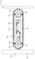
图1示出了显示器组件的前视图,其中显示器处于降低位置。Figure 1 shows a front view of the display assembly with the display in a lowered position.
图2示出了图1的组件的侧视图。FIG. 2 shows a side view of the assembly of FIG. 1 .
图3示出了图1的组件的前视图,其中显示器处于升高位置。Figure 3 shows a front view of the assembly of Figure 1 with the display in a raised position.
图4示出了图3的组件的侧视图。FIG. 4 shows a side view of the assembly of FIG. 3 .
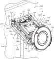
图5示出了支撑臂和支架的等轴视图。Figure 5 shows an isometric view of the support arm and stand.
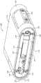
图6示出了支撑臂的等轴视图。Figure 6 shows an isometric view of the support arm.
图7示出了支撑臂的另一个等轴视图。Figure 7 shows another isometric view of the support arm.
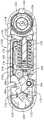
图8示出了沿图7中的剖面线8-8截取的图7的支撑臂的侧视剖视图。FIG. 8 shows a side cross-sectional view of the support arm of FIG. 7 taken along section line 8 - 8 in FIG. 7 .
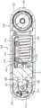
图9示出了沿图7中的剖面线9-9截取的图7的支撑臂的侧视剖视图。FIG. 9 shows a side cross-sectional view of the support arm of FIG. 7 taken along section line 9 - 9 in FIG. 7 .
图10示出了处于降低位置的显示器组件的侧视图。Figure 10 shows a side view of the display assembly in a lowered position.
图11示出了图10的组件的中央侧视剖视图。FIG. 11 shows a central side cross-sectional view of the assembly of FIG. 10 .
图12示出了处于水平位置的图10的显示器组件的侧视图。Figure 12 shows a side view of the display assembly of Figure 10 in a horizontal position.
图13示出了图12的组件的中央侧视剖视图。FIG. 13 shows a central side cross-sectional view of the assembly of FIG. 12 .
图14示出了处于升高位置的图10的显示器组件的侧视图。Figure 14 shows a side view of the display assembly of Figure 10 in a raised position.
图15示出了图14的组件的中央侧视剖视图。FIG. 15 shows a central side cross-sectional view of the assembly of FIG. 14 .
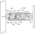
图16示出了显示器组件的另一个实施方案的侧视剖视图,其中支撑臂处于降低位置。16 shows a side cross-sectional view of another embodiment of a display assembly with the support arm in a lowered position.
图17示出了处于水平位置的图16的组件的侧视剖视图。Figure 17 shows a side cross-sectional view of the assembly of Figure 16 in a horizontal position.
图18示出了图17的组件的等轴视图。FIG. 18 shows an isometric view of the assembly of FIG. 17 .
图19示出了处于升高位置的图16的组件的侧视剖视图。Figure 19 shows a side cross-sectional view of the assembly of Figure 16 in a raised position.
图20示出了显示器组件的另一个实施方案的图解侧视图,其中显示器处于升高位置。20 shows a diagrammatic side view of another embodiment of a display assembly with the display in a raised position.
图21为本公开的实施方案的能量相对于臂角度的曲线图。21 is a graph of energy versus arm angle for an embodiment of the disclosure.
具体实施方式Detailed ways
现在将具体地参考在附图中示出的代表性实施方案。应当理解,以下描述不旨在将实施方案限制于任何优选实施方案。相反,其旨在涵盖可被包括在由所附权利要求书限定的所述实施方案的实质和范围内的另选形式、修改形式和等同形式。Reference will now be made in detail to representative embodiments illustrated in the accompanying drawings. It should be understood that the following description is not intended to limit embodiments to any preferred embodiments. On the contrary, it is intended to cover alternatives, modifications and equivalents, which may be included within the spirit and scope of the described embodiments as defined by the appended claims.
以下公开涉及平衡的支撑臂设备,该平衡的支撑臂设备使用止转轭来调节至少一个偏置构件平衡件中的势能,该偏置构件平衡件具有恒定的弹性比率。系统的能量可始终平衡,使得当显示器向下移动并因此失去势能时,附加的相等能量存储在偏置构件的势能中。当显示器的势能改变时,偏置构件可被压缩或扩展,并且压缩或扩展可通过偏置构件与可平移轭或块结构之间的接触来提供,该可平移轭或块结构的平移由止转轭中的旋转轴驱动。The following disclosure relates to a balanced support arm apparatus that uses a yoke to accommodate potential energy in at least one biasing member balance having a constant spring ratio. The energy of the system can always be balanced so that when the display moves down and thus loses potential energy, additional equal energy is stored in the potential energy of the biasing member. When the potential energy of the display changes, the biasing member can be compressed or expanded, and the compression or expansion can be provided by contact between the biasing member and a translatable yoke or block whose translation is stopped by Driven by a rotating shaft in the yoke.
在一些实施方案中,止转轭的移动角速率是显示器支撑臂的旋转的两倍。因此,当臂处于完全竖直向上延伸的取向时,轭连杆也竖直向上延伸,并且当臂向下移动到竖直向下延伸的取向(例如,相对于向上延伸的取向旋转180度)时,止转轭行进90度,同时将能量存储在偏置构件(例如,压缩弹簧)中。偏置构件的压缩速率可与显示器的质量块的简单谐波运动匹配。参见图21。在一些实施方案中,支撑臂可具有约80度(即,相对于水平构型向上约40度并且相对于水平构型向下约40度)、约60度、约90度、约120度、约150度、约180度的总运动范围,或介于任何这些运动范围之间的拟合范围。In some embodiments, the angular rate of movement of the yoke is twice the rotation of the display support arm. Thus, when the arm is in the fully vertically upwardly extending orientation, the yoke link also extends vertically upwardly, and when the arm is moved down to the vertically downwardly extending orientation (eg, rotated 180 degrees relative to the upwardly extending orientation) , the yoke travels 90 degrees while storing energy in a biasing member (eg, a compression spring). The compression rate of the biasing member can be matched to the simple harmonic motion of the mass of the display. See Figure 21. In some embodiments, the support arm can have about 80 degrees (ie, about 40 degrees upward relative to the horizontal configuration and about 40 degrees downward relative to the horizontal configuration), about 60 degrees, about 90 degrees, about 120 degrees, A total range of motion of about 150 degrees, about 180 degrees, or a fitted range in between any of these ranges of motion.
在各种实施方案中,止转轭可由齿轮表面之间的2:1齿轮齿数比驱动,或者由支撑臂的四杆连杆布置中的连杆臂与作为止转轭的一部分的连杆臂之间的2:1角旋转速率驱动。当支撑臂处于水平构型时,止转轭可提供最大扭矩,并且可在升高构型和降低构型两者中提供减小的扭矩(即,相对于水平构型处的扭矩存在扭矩下降)。In various embodiments, the yoke may be driven by a 2:1 gear ratio between the gear surfaces, or by a link arm in a four-bar linkage arrangement that supports the arm and a link arm that is part of the yoke between 2:1 angular rotation rate drives. The yoke can provide maximum torque when the support arm is in the horizontal configuration, and can provide reduced torque in both the raised and lowered configurations (ie, there is a torque drop relative to the torque at the horizontal configuration ).
当支撑臂旋转时,支撑臂可相对于支架的支撑表面或基座以恒定的倾斜角保持显示器。例如,四杆连杆能够以保持第一竖直平面通过四杆连杆的一端(例如,通过一个端部支撑结构中的四杆连杆中的杆的一对枢转点)以及第二竖直平面通过四杆连杆的相对端(例如,通过第二端部支撑结构中的杆的一对枢转点)的平行运动的方式而被集成到臂中。因此,支撑臂可具有由四杆连杆或类似的平行运动设备参考的轭式平衡件。在一些实施方案中,支撑臂的端部还可向附接的显示器提供倾斜(即,显示器围绕连接到显示器的支撑臂的端部的旋转)。When the support arm is rotated, the support arm can hold the display at a constant angle of inclination relative to the support surface or base of the stand. For example, the four-bar linkage can pass through one end of the four-bar linkage (eg, through a pair of pivot points of the rods in the four-bar linkage in one end support structure) and the second vertical while maintaining the first vertical plane. The straight plane is integrated into the arm by means of parallel movement of opposite ends of the four-bar linkage (eg, by means of a pair of pivot points of the bars in the second end support structure). Thus, the support arm may have a yoke-type counterweight referenced by a four-bar linkage or similar parallel motion device. In some embodiments, the end of the support arm may also provide tilt (ie, rotation of the display about the end of the support arm attached to the display) to the attached display.
在一些实施方案中,平衡机构定位在支撑表面和电子显示器之间的支撑臂中的外壳中。平衡机构还可定位在显示器和支撑臂外部的支撑结构中,诸如通过定位在支撑支撑臂的与电子显示器相对定位的端部的支架结构中。In some embodiments, the balance mechanism is positioned in the housing in the support arm between the support surface and the electronic display. The balance mechanism may also be positioned in a support structure external to the display and support arm, such as by being positioned in a stand structure supporting the end of the support arm positioned opposite the electronic display.
具有1:1势能转换的平衡件与支撑臂的端部的平行移动的组合可提供电子显示器在竖直位置之间的经改善的平滑且精确的调节运动。调节显示器所需的输入力也可被约束到期望的水平,因为平衡件不一定使用摩擦来存储能量或防止支撑臂的移动。因此,支撑臂的可枢转部分中的摩擦(例如,四杆连杆中的摩擦盘)可被设计成提供所需的阻力量以进行调节。这样,支撑臂的运动可以是平滑的并且具有最小化的滞后。另外,支撑臂的显示器耦接端部可以附接到枢转构件,该枢转构件被配置为允许显示器相对于支撑臂的显示器耦接端部倾斜,而不会导致显示器耦接端部自身移动或旋转。The combination of the balance with 1:1 potential energy conversion and the parallel movement of the end of the support arm can provide improved smooth and precise adjustment movement of the electronic display between vertical positions. The input force required to adjust the display can also be constrained to a desired level since the balance does not necessarily use friction to store energy or prevent movement of the support arm. Thus, the friction in the pivotable portion of the support arm (eg, the friction disc in the four-bar linkage) can be designed to provide the desired amount of resistance to adjust. In this way, the movement of the support arm can be smooth and with minimal hysteresis. Additionally, the display-coupling end of the support arm may be attached to a pivot member configured to allow the display to tilt relative to the display-coupling end of the support arm without causing the display-coupling end to move itself or rotate.
以下参考附图讨论这些和其他实施方案。然而,本领域的技术人员将容易地理解,本文相对于这些附图所给出的详细描述仅出于说明性目的,而不应被理解为是限制性的。These and other embodiments are discussed below with reference to the figures. However, those skilled in the art will readily appreciate that the detailed description given herein with respect to these drawings is for illustrative purposes only and should not be construed in a limiting sense.
图1-15示出了显示器组件100的各个方面。图1示出了耦接到支撑臂104的电子显示器102的前视图并且图2示出了其右侧视图,该支撑臂耦接到支架106。图3-4示出了在相对于图1-2所示构型的升高位置中耦接到支撑臂104的显示器102。1-15 illustrate various aspects of the
显示器组件100可以是独立组件,其中支撑臂104和支架106被配置为支撑单个显示器102的重量。在一些实施方案中,显示器组件100可省略支架106,并且支撑臂104可耦接到另一个支撑表面或接地表面,诸如例如竖直壁、跨显示器102的宽度侧向延伸并且位于显示器102后面的水平导轨、或另一个类似结构。参见图16的元件1601。
显示器102可包括用于以绘画形式显示信息的电子显示器诸如监视器或类似的视觉输出设备。显示器102可包括显示设备(例如,具有发光二极管(LED)或冷阴极荧光灯(CCFL)背光或有机发光二极管(OLED)显示器的薄膜晶体管液晶显示器(TFT-LCD))、电路、外壳或壳体以及电源。显示器102可被配置为使用连接器和端口诸如数字视觉接口(DVI)连接器、DISPLAYPORT(R)连接器、THUNDERBOLT(R)连接器或其他相关或类似的电接口连接到计算机。
显示器102可包括前向表面108,该前向表面被配置为面向用户并向用户显示信息以供查看。因此,前向表面108可被称为观察表面。前向表面108可为基本上平面的/平坦的或弯曲的(例如,圆柱凹形或凸形)。显示器102可包括被配置为背向用户的后向表面110。支撑臂104可定位在后向表面110和支架106之间。支撑臂104能够在后向表面110处或在显示器102的后侧部分中可释放地耦接到显示器102。在一些实施方案中,支撑臂104可在显示器附接点115处附接到显示器102。
支撑臂104还可耦接到支架106。支架106可包括被配置为在显示器102下方延伸的基座112,并且可包括被配置为从基座112向上延伸并位于显示器102的后向表面110后面的竖直支撑件114。竖直支撑件114可具有顶端,支撑臂104在所述顶端处附接在支架附接点116处。因此,支架106可被称为具有大致L形轮廓,其中显示器102被定位在L形的基座部分112上方,如图2和4所示。The
支撑臂104可将显示器102相对于支架106保持在适当位置,并且可将显示器102相对于支架106保持在用户选择的竖直位置。支撑臂104可将显示器保持在多个不同位置,包括降低位置(如图1-2所示)和升高位置(如图3-4所示),其中显示器102的位置保持静止(即,由于显示器102的重量向下拉动支撑臂104而不会向下漂移或下垂)。用户可提供在竖直方向上取向的输入力以相对于支架106升高显示器102,如图2中的力F1所示,或者用户可提供竖直取向的输入力F2以相对于支架106降低显示器102,如图4所示。当显示器102移动时,其可行进通过弧形路径,该弧形路径具有由支撑臂104的长度限定的半径。参见图10-15及其在下文中的相关描述。The
图5-9示出了根据本公开的实施方案的支撑臂104的视图。支撑臂104可包括具有第一端部120和第二端部122的外壳118。第一端部120可邻近支架106(相对于第二端部122)定位,并且第二端部122可邻近显示器102(相对于第一端部120)定位。外壳118可包括平滑、坚硬的外表面,并且可包括刚性材料,诸如刚性金属、陶瓷或塑料。支撑臂104可包括具有平坦侧表面和弯曲端面的大致细长形状。在图5-9中,示出了支撑臂104,其中外壳118的一些侧表面被省略,以便示出支撑臂104的内部部件。5-9 illustrate views of the
在外壳118内,支撑臂104可包括定位在第一端部120中的第一端部支撑件124和定位在第二端部122中的第二端部支撑件126。参见图5-7。第一端部支撑件124可耦接到支架106或支撑臂104外部的另一个支撑表面。第二端部支撑件126可耦接到显示器102或耦接到定位在外壳118的第二端部122处的显示器安装装置128。显示器安装装置128可附接到中间显示器连接器130。中间显示器连接器130可以是被配置为附接到显示器102的元件,诸如被磁性吸引到显示器102的磁性元件或被配置为与显示器102的一部分机械性互锁的联锁元件。外壳118能够相对于第一端部支撑件124和第二端部支撑件126绕图5,6和8所示的一对枢转轴线132,134旋转。Within the
第一杆136和第二杆138可附接到第一端部支撑件124上的枢转点140,142,并且可附接到第二端部支撑件126上的枢转点144,146。第一杆136和第二杆138可相对于其相应的连接的枢转点140,142,144,146枢转。第一杆136和第二杆138可在枢转点之间具有相等的长度。例如,第一杆136在枢转点140和144之间的长度可等于第二杆138在枢转点142,146之间的长度。第一杆136和第二杆138可平行于彼此布置在降低位置、水平位置和升高位置(即,分别为图10,12和14的位置)。因此,第一端部支撑件124上的枢转点140,142之间的距离可等于第二端部支撑件126上的枢转点144,146之间的距离。因此,这四个枢转点140,142可限定四边形平行四边形148的拐角,如图10,12和14所示。The
施加到显示器102(例如,F1或F2)或施加到支撑臂104的输入力可以使第一杆136和第二杆138相对于第一端部支撑件124旋转,旋转轴穿过枢转点140,142。第一杆136和第二杆138也可旋转地附接到第二端部支撑件126,因此杆136,138在第一端部支撑件124处的旋转也引起第二端部支撑件126处围绕其相关联的枢转点144,146的相等量值的旋转。为此,延伸穿过第一端部支撑件枢转点140,142的线总是平行于延伸穿过第二端部支撑件枢转点144,146的线。附近成对的枢转点140/142,144/146的平行移动确保当支撑臂104围绕枢转轴线132在图10,12和14所示的位置之间移动时,显示器102不相对于显示器安装装置128或显示器连接器130旋转。当杆136,138旋转时,第一端部枢转点140,142可相对于彼此静止,并且当杆136,138旋转时,第二端部枢转点144,146也可相对于彼此静止。在一些实施方案中,显示器安装装置128能够以允许显示器102倾斜而不移动支撑臂104的方式围绕第二枢转轴线134独立于外壳118并且独立于第二端部支撑件126旋转。An input force applied to the display 102 (eg, F1 or F2 ) or to the
第一杆136和第二杆138可被称为四杆连杆或四连接件、四接头、闭环连杆的一部分。第一杆136和第二杆138可以是四杆连杆中的两个连接件,并且第一端部支撑件124和第二端部支撑件126可以是剩余的两个连接件。第一杆136和第二杆138可旋转而不相对于彼此平移,并且第一端部支撑件124和第二端部支撑件126可相对于彼此平移而不相对于彼此旋转。The
支撑臂104可包括至少一个四杆连杆。在一些实施方案中,四杆连杆定位在外壳118内的不同点处。例如,如图4,5和7所示,第三杆150和第四杆152可设置在外壳118中与第一杆136和第二杆138相对的一侧上。在一些实施方案中,多个四杆连杆可用完全分开的连接件或杆构造。在一些情况下,四杆连杆可共用连接件或杆,诸如第三杆150和第四杆152如何枢转地连接到与第一杆136和第二杆138相同的第一端部支撑件124和第二端部支撑件126。参见图5和7。The
外壳118的内部还可包括平衡机构154(即,平衡组件或储能结构)。平衡机构154可包括至少一个储能设备156和至少一个轭158。平衡机构154可被配置为当显示器102的势能响应于向上或向下移动而改变时在内部存储或释放势能。The interior of the
储能设备156可包括一个或多个弹簧(例如,可弹性压缩的线圈、气弹簧、弹性体材料、可弹性延伸的线圈、可重力位移的配重、缆线和滑轮、类似的设备以及它们的组合)。在一些实施方案中,弹簧以并列构型定位,这可减小支撑臂104的竖直厚度,同时仍然提供显著的弹簧力和储能容量。参见图7中的储能设备160。The
储能设备156可定位在支撑臂104中或支撑臂的外部(参见图20)。储能设备156可通过被压缩(例如,就压缩弹簧而言)来储能,可通过膨胀(例如,就拉伸弹簧而言)来储能,或可通过移动(例如,就可移动配重而言)来储能。平衡机构154可被配置为确保储能设备156中存储的能量等于通过向下移动显示器102而损失的能量,并且确保从储能设备156损失的能量等于通过向上移动显示器102而获得的能量。The
压缩弹簧被示出为图5-15的储能设备156,并且弹簧被示出为在图11所示的降低位置具有最大压缩(即,沿着支撑臂104的长度尺寸的最小长度)。弹簧在图13所示的水平位置具有较小的压缩,并且在图15所示的升高位置具有最小压缩。因此,压缩弹簧在最小高度降低位置中存储最多的能量,并且在最大高度升高位置中存储最少的能量。The compression spring is shown as the
储能设备156的压缩或扩展速率可与显示器102的质量的简单谐波运动相匹配。储能设备156可包括具有恒定弹性比率的线性弹簧以提供此行为。还可参见图21和下文的相关说明。The rate of compression or expansion of the
储能设备156可通过轭158的操作来调节其势能。轭158可包括接合储能设备156的可平移块162和用于调节块162的位置的平衡臂164。平衡臂164可在平衡枢转点166处安装到外壳118,并且可具有接触所述块162的表面170(参见图8)的从动件168。从动件168可为辊或圆形表面诸如凸轮从动件,并且可被配置为保持与表面170恒定接触。平衡臂164还可包括臂齿轮表面172,该臂齿轮表面被配置为接合第一端部支撑件124的端部支撑齿轮表面174。轭158可被称为止转轭或轭机构,其被配置为能够将平衡臂164的旋转运动转换为块162的平移运动。The
当支撑臂104移动时,外壳118旋转,从而相对于延伸穿过第一端部支撑件124的枢转轴线132移动平衡枢转点166。参见图8。齿轮表面172,174的接合使得平衡臂164围绕枢转点166旋转,从而驱动从动件168通过围绕枢转点166的弧形路径。从动件168的纵向位置(即从动件沿着外壳118的纵向轴线L(参见图11)的位置)因此随着外壳118的旋转而改变。在支撑臂104的最小降低位置处,从动件168处于远离枢转轴线132的最大纵向位移处,如图11所示。在支撑臂104的最大升高位置处,从动件168处于距枢转轴线132的最小纵向位移处,如图15所示。由于从动件168的弧形路径围绕枢转点166移动,与在支撑臂104处于升高位置时从动件168与枢转轴线132之间的纵向距离根据支撑臂104的旋转度的变化率相比,在支撑臂104处于降低位置时从动件168与枢转轴线132之间的纵向距离根据支撑臂104的旋转度的变化率较低。该变化率反映在图21的弹簧势能曲线2104的周期性正弦波状曲率中。As the
储能设备156可将可平移块162朝向枢转轴线132偏置。因此,从动件168沿着外壳118的纵向轴线朝向枢转轴线132的移动允许储能设备156扩展,并且从动件168朝向枢转轴线134的移动可压缩储能设备156。储能设备156的扩展可释放其势能,并且其压缩可存储势能。储能设备156的弹性特征可被设计成确保由支撑臂104的旋转引起的储能设备156的势能的变化精确地抵消由显示器102的质量块(以及附接到其的同样竖直移动的任何其他部件)的竖直移动引起的势能的变化。还参见图21及其在本文中的相关描述。The
臂齿轮表面172和支撑齿轮表面174之间的齿轮齿数比可被设计成提供支撑臂104围绕枢转轴线132的角位移与平衡臂164围绕平衡枢转点166的角位移的2:1比率。例如,如图11所示,支撑臂104可具有相对于水平轴线X成角度A1定位的纵向轴线L,并且平衡臂164可具有的轴线P,该轴线P穿过平衡枢转点166以及相对于平行于纵向轴线L的轴线以角度B1取向的从动件168的中心。在各种实施方案中,轴线P可延伸穿过枢转点166并且穿过平衡臂164中的另一个单个点。角度A1指示支撑臂104在水平轴线X下方约45度角处,并且角度B1指示从动件168在相对于水平轴线X约30度角处。The gear ratio between
在图13的水平构型中,支撑臂104已将其纵向轴线L旋转到从水平轴线X偏移约零度,并且角度B2的量值相对于纵向轴线L已增加至约52.5度。因此,作为响应,角度A1已从约负45度增加至约零度,并且角度B1已增加约22.5度。到B2的约22.5度变化为纵向轴线L的角位移量的约二分之一。In the horizontal configuration of Figure13 , the
在图15的升高构型中,支撑臂104已将其纵向轴线L旋转至水平轴线X上方约45度角A2,并且角B3已增加至约75度。因此,支撑臂104的纵向轴线L的每个角位移度与延伸穿过平衡枢转点166和平衡臂164上的另一个固定点的轴线P的角位移的约二分之一相关联。支撑臂104的旋转速率可以是轴P的旋转速率的两倍。In the raised configuration of Figure15 , the
轭158的块162可在由储能设备156或平衡臂164驱动时在外壳118内平移。如图5,7,8和9所示,块162可包括装配到纵向细长狭槽178中的侧向延伸的轴176。纵向取向的狭槽178可形成于作为外壳118的一部分并且相对于该外壳静止的块中。因此,当支撑臂104如图10-15所示旋转时,可沿狭槽178引导轴176以限制块162相对于外壳118或储能设备156的旋转。轴176可约束块162沿着延伸穿过枢转轴线132,134的纵向轴线L平移。在一些实施方案中,轴176可包括轮、辊或类似设备以减小轴176和狭槽178之间的摩擦。在一些实施方案中,轴176从块162沿相反方向侧向延伸并进入定位在块162的相对侧上的两个狭槽178中。
支撑臂104的角位移范围可通过外壳118与外壳118外部的表面之间的接触来限制,诸如通过外壳118与支架106之间或外壳118与显示器连接器130或显示器102之间的接触。在一些实施方案中,角位移的范围可通过在支撑臂104内移动的部件之间的接触来限制。例如,如图9所示,支撑臂104可包括角限制块180,该角限制块被配置为与外壳118一起围绕第一枢转轴线132旋转并且相对于第一端部支撑件124旋转。角限制块180可具有第一侧表面182和第二侧表面184,所述第一侧表面和第二侧表面被配置为当角限制块180相对于水平轴线X旋转到相应的预定最大角度和最小角度时与第一端部支撑件124的对应表面接触。The range of angular displacement of
角度C示出了第二侧表面184如何相对于水平轴线X以一定角度取向。当支撑臂104向下旋转(例如,旋转到图10的位置)时,第二侧表面184相对于枢转轴线132旋转,直到其接触第一端部支撑件124,从而防止外壳118相对于第一端部支撑件124进一步向下旋转。第一侧表面182执行用于向上旋转的类似功能。角度C以及第二侧表面184与第一端部支撑件124之间的距离可被设计成限定向下角位移的期望范围,并且类似的角度和距离可被设计成限定向上角位移的范围。两个侧表面182,184之间的角度可限定支撑臂104的角位移的总范围。Angle C shows how the
使用角限制块180限制角位移可防止外壳118与支架106或显示器102之间的接触,从而减少它们将彼此划伤或凹陷的可能性。其还可在支架106和显示器102之间提供预定量的间隙空间或偏移,这可有利地改善通过间隙或偏移的空气循环和线缆布线。Limiting the angular displacement using the
图16-19示出了可以与支撑臂104类似的方式使用的支撑臂1604的另一个实施方案。在这些图中,具有类似编号的元件可起到与图1-15的实施方案的元件类似的功能。图16是处于降低位置的具有外壳1618的侧面板的支撑臂1604的侧视剖视图,其中顶部侧杆1636和底部侧杆1638被移除以露出内部部件(图18中示出了一个相对的顶部侧杆1686)。图17是处于水平位置的支撑臂1604的侧视图,并且图19是处于升高位置的支撑臂1604的侧视图。图18示出了处于水平位置的支撑臂1604的等轴视图,其中省略了外壳1618的侧部和顶部以及侧杆1636,1638。16-19 illustrate another embodiment of a
支撑臂1604可包括至少一个四杆连杆以控制显示器102相对于支架106的平行运动。因此,支撑臂1604可以与支撑臂104类似的方式操作,如图10,12和14所示。因此,图16-19示出了支撑臂1604内的平衡机构1658的特征。平衡机构1658可包括在引导显示器102的运动的四杆连杆内的四杆连杆。至少一个储能设备1656可定位在外壳1618中并且可与平衡块1662和第二端部支撑件1626耦接。块1662可响应于由储能设备1656和包括平衡臂1664和转换臂1688的平衡连杆施加的力而在外壳1618内平移。平衡臂1664可在平衡枢转点1666处枢转地连接到外壳1618,并且可在从动件1668处接触块1662。转换臂1688可在端部支撑件枢转点1690处枢转地连接到第一端部支撑件1624,并且在臂枢转点1692处枢转地连接到平衡臂1664。枢转点1666,1690,1692和外壳1618相对于第一端部支撑件1624的枢转轴线可在支撑臂1604内形成四杆连杆的接头。外壳1618、第一端部支撑件1624、平衡臂1664和转换臂1688可为平衡机构的四杆连杆中的连接件。The
当块1662沿着支撑臂1604的纵向轴线平移时,储能设备1656可存储或释放势能。平衡臂1664的旋转可由转换臂1688驱动,而不是由诸如上文相对于其他实施方案所述的齿轮相互作用驱动。如图16-19所示,当支撑臂1604旋转时,外壳1618相对于第一端部支撑件1624旋转。因为平衡臂1664在枢转点1666处附接到外壳1618,所以平衡臂1664与外壳1618一起相对于第一端部支撑件1624移动。平衡枢转点1666和端部支撑件枢转点1690之间的距离随着外壳1618的移动而改变,因此转换臂1688相对于第一端部支撑件1624旋转。由于臂枢转点1692处的附接,平衡臂1664也同时围绕平衡枢转点1666旋转。各个枢转点1666,1690,1692与从动件1668之间的距离可提供外壳1618的角位移与通过平衡枢转点1666和平衡臂1664上的另一个点(例如,从动件1668)或通过平衡臂1664上的另两个一致点的轴线的角位移的2:1比率。The
例如,如图16所示,穿过臂枢转点1692和从动件1668的轴线大致平行于外壳1618的纵向轴线。在外壳1618向上旋转约90度之后,如图19所示,穿过元件1668和1692的相同轴线相对于外壳1618的纵向轴线成约45度角。该转换比率可控制块1662沿外壳1618的纵向轴线的平移量,并且因此可根据需要控制储能设备1656的势能的变化,以抵消连接的显示器102的质量块的势能的变化。还参见图21和本文的相关说明。For example, as shown in FIG. 16 , the axis passing through the
在一些实施方案中,第一端部支撑件1624可包括角位移限制特征部。转换臂1688可定位在具有下侧表面1696和上侧表面1698的第一端部支撑件1624中的凹槽1694内。下侧表面1696和上侧表面1698可在外壳1618的相应最小旋转位置和最大旋转位置处接触转换臂1688,如图16和19所示。因此,由下侧表面1696和上侧表面1698形成的角度可限定转换臂1688的运动范围并且因此可限定整个支撑臂1604的运动范围。转换臂1688与侧表面1696,1698之间的干涉可防止平衡臂1664及其附接的外壳1618移动。In some embodiments, the
图20示出了支撑系统2000的另一个实施方案,其中显示器2002通过连杆2004安装到支架2006,该连杆具有连杆2004外部和支架2006内的平衡机构2008。在该实施方案中具有类似名称的元件可起到与本文所述的其他实施方案类似的功能。FIG. 20 shows another embodiment of the
连杆2004可为具有四个枢转点2010,2012,2014,2016的四杆平行四边形连杆。在该实施方案中,显示器2002的外壳提供联接枢转点2010和2012的四杆构型的一部分。支架2006的外壳提供联接枢转点2014和2016的四杆构型的一部分。在一些实施方案中,单独的杆可分别联接点2010/2012和2014/2016,并且那些单独的杆可安装到显示器2002或支架2006(例如,类似于第一端部支撑件124和第二端部支撑件126)。因此,当连杆2004的第一杆2020和第二杆2022旋转时,由于穿过点2010和2012的线平行于穿过点2014和2016的线,因此显示器2002可平行于支架2006的竖直轴线移动。
平衡机构2008可具有转换臂2023,所述转换臂在第一杆2020和第二杆2022中的至少一者上的枢转点2024处联接到杆中的一者。转换臂2023可在臂枢转点2025处枢转地附接到平衡臂2026。平衡臂2026可在平衡枢转点2028处枢转地附接到支架2006的外壳,并且可具有从动件2030部分,该从动件部分接合定位在支架2006内的可平移块2032。块2032与储能设备2034接触,并且储能设备2034在一端2036处被约束。The
当连杆2004使杆2020,2022旋转时,枢转点2024可沿着弧形路径围绕枢转点2014移动。枢转点2024的移动驱动臂枢转点2025和平衡臂2026围绕平衡枢转点2028的旋转。平衡臂2026的旋转引起从动件2030的竖直运动,从而压缩或扩展储能设备2034,同时底端2036相对于支架2006保持静止。因此,该实施方案示出了四杆连杆2004可如何支持和引导显示器2002的运动,并且止转轭式平衡件可被定位在连杆2004的外部。When the
图21提供了根据本公开的实施方案的能量与臂角度的曲线图2100。臂角度可被定义为支撑臂(例如,104或1604)相对于水平方向(例如,水平轴线X)的角度。重力势能2102可被定义为显示器的质量块和支撑组件的任何其他连接部件的随支撑臂的移动而变化的势能。如本文所定义,当支撑臂水平时,重力势能2102为零。重力势能随着支撑臂升高而增加,并且其随着支撑臂降低而降低。21 provides a
为了确保支撑臂的平滑和不费力的操作,可经由平衡机构控制系统中的弹簧或其他储能设备的势能2104,以具有以与重力势能2102大小相同方向相反的速率变化的量值。因此,系统能量2106(其表示所有臂角度下的重力势能2102和弹簧势能2104的总和)可在臂旋转时保持恒定。因此,需要非常小的输入力来改变显示器的势能(即,竖直位置),因为弹簧势能提供补充能量以在显示器移动时帮助支撑臂的旋转。重力和弹簧势能的变化可在量值上与显示器和所连接的移动部件的质量的简单谐波运动相关联。To ensure smooth and effortless operation of the support arm, the
在适用于本技术的限度内,采集和使用得自各种来源的数据可以被用于改进向用户递送其可能感兴趣的启发内容或任何其他内容。本公开预期,在一些实例中,这些所采集的数据可包括唯一地识别或可用于联系或定位特定人员的个人信息数据。此类个人信息数据可以包括人口统计数据、基于位置的数据、电话号码、电子邮件地址、
本公开认识到在本发明技术中使用此类个人信息数据可用于使用户受益。例如,该个人信息数据可用于递送用户较感兴趣的目标内容。因此,使用此类个人信息数据使得用户能够对所递送的内容进行有计划的控制。此外,本公开还预期个人信息数据有益于用户的其他用途。例如,健康和健身数据可用于向用户的总体健康状况提供见解,或者可用作使用技术来追求健康目标的个人的积极反馈。This disclosure recognizes that the use of such personal information data in the present technology can be used to benefit users. For example, the personal information data can be used to deliver targeted content of greater interest to the user. Thus, the use of such personal information data enables the user to exercise programmatic control over the content delivered. In addition, this disclosure also contemplates other uses of personal information data that benefit the user. For example, health and fitness data can be used to provide insights into a user's overall health, or can be used as positive feedback for individuals using technology to pursue health goals.
本公开设想负责采集、分析、公开、传输、存储或其他使用此类个人信息数据的实体将遵守既定的隐私政策和/或隐私实践。具体地,此类实体应当实行并坚持使用被公认为满足或超出对维护个人信息数据的隐私性和安全性的行业或政府要求的隐私政策和实践。此类政策应该能被用户方便地访问,并应随着数据的采集和/或使用变化而被更新。来自用户的个人信息应当被收集用于实体的合法且合理的用途,并且不在这些合法使用之外共享或出售。此外,应在收到用户知情同意后进行此类采集/共享。此外,此类实体应考虑采取任何必要步骤,保卫和保障对此类个人信息数据的访问,并确保有权访问个人信息数据的其他人遵守其隐私政策和流程。另外,这种实体可使其本身经受第三方评估以证明其遵守广泛接受的隐私政策和实践。此外,应当调整政策和实践,以便采集和/或访问的特定类型的个人信息数据,并适用于包括管辖范围的具体考虑的适用法律和标准。例如,在美国,对某些健康数据的收集或获取可能受联邦和/或州法律的管辖,诸如健康保险流通和责任法案(HIPAA);而其他国家的健康数据可能受到其他法规和政策的约束并应相应处理。因此,在每个国家应为不同的个人数据类型保持不同的隐私实践。This disclosure contemplates that entities responsible for collecting, analyzing, disclosing, transmitting, storing, or otherwise using such personal information data will comply with established privacy policies and/or privacy practices. Specifically, such entities should implement and adhere to privacy policies and practices that are recognized as meeting or exceeding industry or governmental requirements for maintaining the privacy and security of personal information data. Such policies should be easily accessible to users and should be updated as data collection and/or usage changes. Personal information from users should be collected for the entity's lawful and reasonable uses and not shared or sold outside of those lawful uses. In addition, such collection/sharing should take place after the informed consent of the user has been received. In addition, such entities should consider taking any necessary steps to safeguard and secure access to such personal information data and ensure that others who have access to personal information data comply with their privacy policies and procedures. Additionally, such entities may subject themselves to third-party assessments to demonstrate compliance with generally accepted privacy policies and practices. In addition, policies and practices should be adjusted for the specific types of personal information data collected and/or accessed, and for applicable laws and standards including jurisdiction-specific considerations. For example, in the United States, the collection or acquisition of certain health data may be governed by federal and/or state laws, such as the Health Insurance Portability and Accountability Act (HIPAA); while health data in other countries may be governed by other regulations and policies and should be dealt with accordingly. Therefore, different privacy practices should be maintained in each country for different types of personal data.
不管前述情况如何,本公开还预期用户选择性地阻止使用或访问个人信息数据的实施方案。即本公开预期可提供硬件元件和/或软件元件,以防止或阻止对此类个人信息数据的访问。例如,就广告递送服务而言,本发明技术可被配置为在注册服务期间或之后任何时候允许用户选择“选择加入”或“选择退出”参与对个人信息数据的收集。在另一示例中,用户可以选择不为目标内容递送服务提供情绪相关数据。在另一个示例中,用户可选择限制情绪相关数据被保持的时间长度,或完全禁止基础情绪状况的开发。除了提供“选择加入”和“选择退出”选项外,本公开设想提供与访问或使用个人信息相关的通知。例如,可在下载应用时向用户通知其个人信息数据将被访问,然后就在个人信息数据被应用访问之前再次提醒用户。Regardless of the foregoing, the present disclosure also contemplates implementations in which users selectively block the use or access to personal information data. That is, the present disclosure contemplates that hardware elements and/or software elements may be provided to prevent or prevent access to such personal information data. For example, with respect to advertising delivery services, the present technology may be configured to allow users to "opt-in" or "opt-out" to the collection of personal information data during registration for the service or at any time thereafter. In another example, the user may choose not to provide sentiment-related data for the targeted content delivery service. In another example, the user may choose to limit the length of time that mood-related data is retained, or to disable the development of the underlying mood condition altogether. In addition to providing "opt-in" and "opt-out" options, this disclosure contemplates providing notices related to access or use of personal information. For example, the user can be notified when the application is downloaded that their personal information data will be accessed, and then the user is reminded again just before the personal information data is accessed by the application.
此外,本公开的目的是应管理和处理个人信息数据以最小化无意或未经授权访问或使用的风险。一旦不再需要数据,通过限制数据收集和删除数据可最小化风险。此外,并且当适用时,包括在某些健康相关应用程序中,数据去标识可用于保护用户的隐私。可在适当时通过移除具体标识符(例如,出生日期等)、控制所存储数据的量或特异性(例如,在城市级别而不是在地址级别收集位置数据)、控制数据如何被存储(例如,在用户上聚集数据)、和/或其他方法来促进去标识。Furthermore, the purpose of this disclosure is that personal information data should be managed and processed to minimize the risk of unintentional or unauthorized access or use. Risk is minimized by limiting data collection and deleting data once it is no longer needed. Additionally, and when applicable, including in certain health-related applications, data de-identification may be used to protect the privacy of users. This can be done by removing specific identifiers (eg, date of birth, etc.), controlling the amount or specificity of the data stored (eg, collecting location data at the city level instead of the address level), controlling how the data is stored (eg, , aggregate data on users), and/or other methods to facilitate de-identification.
因此,虽然本公开广泛地覆盖了使用个人信息数据来实现一个或多个各种所公开的实施方案,但本公开还预期各种实施方案也可在无需访问此类个人信息数据的情况下被实现。即,本发明技术的各种实施方案不会由于缺少此类个人信息数据的全部或一部分而无法正常进行。例如,可通过基于非个人信息数据或绝对最低数量的个人信息诸如与用户相关联的设备所请求的内容、对内容递送服务可用的其他非个人信息或公开可用的信息来推断偏好,从而选择内容并将该内容递送至用户。Thus, while this disclosure broadly covers the use of personal information data to implement one or more of the various disclosed embodiments, this disclosure also contemplates that the various embodiments may also be used without access to such personal information data. accomplish. That is, various implementations of the present technology will not fail due to lack of all or a portion of such personal information data. For example, content may be selected by inferring preferences based on non-personal information data or an absolute minimum amount of personal information such as content requested by a device associated with the user, other non-personal information available to content delivery services, or publicly available information and deliver that content to the user.
为了说明的目的,前述描述使用具体命名以提供对所述实施方案的透彻理解。然而,对于本领域的技术人员而言将显而易见的是,不需要具体细节即可实践所述实施方案。因此,出于例示和描述的目的,呈现了对本文所述的具体实施方案的前述描述。它们并非意在穷举或将实施方案限制到所公开的精确形式。对于本领域的普通技术人员而言将显而易见的是,鉴于上面的教导内容,许多修改和变型是可行的。For purposes of illustration, the foregoing description uses specific nomenclature to provide a thorough understanding of the described embodiments. However, it will be apparent to those skilled in the art that specific details are not required to practice the described embodiments. Thus, the foregoing descriptions of the specific embodiments described herein have been presented for the purposes of illustration and description. They are not intended to be exhaustive or to limit the embodiments to the precise forms disclosed. It will be apparent to those of ordinary skill in the art that many modifications and variations are possible in light of the above teachings.
Claims (20)
Priority Applications (1)
| Application Number | Priority Date | Filing Date | Title |
|---|---|---|---|
| CN202210277061.7ACN114636074B (en) | 2019-05-31 | 2020-05-25 | Lifting arm of display |
Applications Claiming Priority (4)
| Application Number | Priority Date | Filing Date | Title |
|---|---|---|---|
| US201962855315P | 2019-05-31 | 2019-05-31 | |
| US62/855,315 | 2019-05-31 | ||
| US16/583,222 | 2019-09-25 | ||
| US16/583,222US11415201B2 (en) | 2019-05-31 | 2019-09-25 | Display lift arm |
Related Child Applications (1)
| Application Number | Title | Priority Date | Filing Date |
|---|---|---|---|
| CN202210277061.7ADivisionCN114636074B (en) | 2019-05-31 | 2020-05-25 | Lifting arm of display |
Publications (2)
| Publication Number | Publication Date |
|---|---|
| CN112013235Atrue CN112013235A (en) | 2020-12-01 |
| CN112013235B CN112013235B (en) | 2022-04-05 |
Family
ID=73506569
Family Applications (1)
| Application Number | Title | Priority Date | Filing Date |
|---|---|---|---|
| CN202010451703.1AActiveCN112013235B (en) | 2019-05-31 | 2020-05-25 | monitor lift arm |
Country Status (1)
| Country | Link |
|---|---|
| CN (1) | CN112013235B (en) |
Cited By (4)
| Publication number | Priority date | Publication date | Assignee | Title |
|---|---|---|---|---|
| CN115199873A (en)* | 2021-04-08 | 2022-10-18 | 苹果公司 | Reconfigurable stent ecosystem |
| CN117082998A (en)* | 2021-12-22 | 2023-11-17 | 爱格升公司 | Adjustable and stowable workstation assembly |
| US12372193B2 (en) | 2021-04-08 | 2025-07-29 | Apple Inc. | Reconfigurable stand ecosystem |
| US12429920B2 (en) | 2021-04-08 | 2025-09-30 | Apple Inc. | Reconfigurable stand ecosystem |
Citations (18)
| Publication number | Priority date | Publication date | Assignee | Title |
|---|---|---|---|---|
| US4160536A (en)* | 1976-10-27 | 1979-07-10 | Jac. Jacobsen A/S | Counterbalanced arm |
| FR2605757A1 (en)* | 1986-10-27 | 1988-04-29 | Binet Alain | PHOTOGRAPHIC REFLECTOR |
| US5170975A (en)* | 1991-06-06 | 1992-12-15 | Alan Chadwick | Articulated arm with spring for counterbalancing |
| US5501420A (en)* | 1994-06-17 | 1996-03-26 | Weber-Knapp Company | Counterbalance mechanism |
| US20040035989A1 (en)* | 2002-08-21 | 2004-02-26 | Sweere Harry C. | Stand |
| CN1633571A (en)* | 2001-11-08 | 2005-06-29 | 苹果电脑公司 | Computer controlled display device |
| TWM334587U (en)* | 2008-01-07 | 2008-06-11 | Ever Case Technology Inc | Cantilever structure of fixing frame |
| CN101965546A (en)* | 2007-07-17 | 2011-02-02 | 麦尔斯顿Av技术有限责任公司 | Mount and electronic display system |
| TW201127325A (en)* | 2010-02-11 | 2011-08-16 | xian-yao Qiu | Hanger structure |
| GB201113272D0 (en)* | 2011-08-01 | 2011-09-14 | Colebrook Bosson & Saunders Products Ltd | Adjustable support system |
| US8070115B2 (en)* | 2007-12-27 | 2011-12-06 | Hong Fu Jin Precision Industry (Shenzhen) Co., Ltd. | Support stand for flat-panel monitor and elevating support for support stand |
| US20120192382A1 (en)* | 2011-01-31 | 2012-08-02 | Weber Knapp Company | Counterbalance mechanism |
| US20120235000A1 (en)* | 2011-03-18 | 2012-09-20 | Borloz Paul Rene | Variable height arm structures, systems, and methods |
| CN103047524A (en)* | 2013-01-16 | 2013-04-17 | 深圳市开立科技有限公司 | Display screen adjusting arm and device thereof |
| CN103080626A (en)* | 2010-07-30 | 2013-05-01 | 爱格升公司 | Cam balance mechanism systems and methods |
| CN105605379A (en)* | 2010-07-08 | 2016-05-25 | 索斯科公司 | Display support apparatus |
| CN108779891A (en)* | 2016-03-07 | 2018-11-09 | 索斯科公司 | Display support arm component for installing display |
| CN109764084A (en)* | 2019-03-01 | 2019-05-17 | 江苏海事职业技术学院 | A gradient type shock-resistant ship base |
- 2020
- 2020-05-25CNCN202010451703.1Apatent/CN112013235B/enactiveActive
Patent Citations (18)
| Publication number | Priority date | Publication date | Assignee | Title |
|---|---|---|---|---|
| US4160536A (en)* | 1976-10-27 | 1979-07-10 | Jac. Jacobsen A/S | Counterbalanced arm |
| FR2605757A1 (en)* | 1986-10-27 | 1988-04-29 | Binet Alain | PHOTOGRAPHIC REFLECTOR |
| US5170975A (en)* | 1991-06-06 | 1992-12-15 | Alan Chadwick | Articulated arm with spring for counterbalancing |
| US5501420A (en)* | 1994-06-17 | 1996-03-26 | Weber-Knapp Company | Counterbalance mechanism |
| CN1633571A (en)* | 2001-11-08 | 2005-06-29 | 苹果电脑公司 | Computer controlled display device |
| US20040035989A1 (en)* | 2002-08-21 | 2004-02-26 | Sweere Harry C. | Stand |
| CN101965546A (en)* | 2007-07-17 | 2011-02-02 | 麦尔斯顿Av技术有限责任公司 | Mount and electronic display system |
| US8070115B2 (en)* | 2007-12-27 | 2011-12-06 | Hong Fu Jin Precision Industry (Shenzhen) Co., Ltd. | Support stand for flat-panel monitor and elevating support for support stand |
| TWM334587U (en)* | 2008-01-07 | 2008-06-11 | Ever Case Technology Inc | Cantilever structure of fixing frame |
| TW201127325A (en)* | 2010-02-11 | 2011-08-16 | xian-yao Qiu | Hanger structure |
| CN105605379A (en)* | 2010-07-08 | 2016-05-25 | 索斯科公司 | Display support apparatus |
| CN103080626A (en)* | 2010-07-30 | 2013-05-01 | 爱格升公司 | Cam balance mechanism systems and methods |
| US20120192382A1 (en)* | 2011-01-31 | 2012-08-02 | Weber Knapp Company | Counterbalance mechanism |
| US20120235000A1 (en)* | 2011-03-18 | 2012-09-20 | Borloz Paul Rene | Variable height arm structures, systems, and methods |
| GB201113272D0 (en)* | 2011-08-01 | 2011-09-14 | Colebrook Bosson & Saunders Products Ltd | Adjustable support system |
| CN103047524A (en)* | 2013-01-16 | 2013-04-17 | 深圳市开立科技有限公司 | Display screen adjusting arm and device thereof |
| CN108779891A (en)* | 2016-03-07 | 2018-11-09 | 索斯科公司 | Display support arm component for installing display |
| CN109764084A (en)* | 2019-03-01 | 2019-05-17 | 江苏海事职业技术学院 | A gradient type shock-resistant ship base |
Cited By (7)
| Publication number | Priority date | Publication date | Assignee | Title |
|---|---|---|---|---|
| CN115199873A (en)* | 2021-04-08 | 2022-10-18 | 苹果公司 | Reconfigurable stent ecosystem |
| CN115199873B (en)* | 2021-04-08 | 2025-01-10 | 苹果公司 | Reconfigurable stent ecosystem |
| US12372193B2 (en) | 2021-04-08 | 2025-07-29 | Apple Inc. | Reconfigurable stand ecosystem |
| US12429920B2 (en) | 2021-04-08 | 2025-09-30 | Apple Inc. | Reconfigurable stand ecosystem |
| CN117082998A (en)* | 2021-12-22 | 2023-11-17 | 爱格升公司 | Adjustable and stowable workstation assembly |
| CN117082998B (en)* | 2021-12-22 | 2025-05-27 | 爱格升公司 | Adjustable and stowable workstation assembly |
| US12404970B2 (en) | 2021-12-22 | 2025-09-02 | Ergotron, Inc. | Adjustable and stowable workstation assembly |
Also Published As
| Publication number | Publication date |
|---|---|
| CN112013235B (en) | 2022-04-05 |
Similar Documents
| Publication | Publication Date | Title |
|---|---|---|
| CN114636074B (en) | Lifting arm of display | |
| CN112013235A (en) | monitor lift arm | |
| US12000524B2 (en) | Dual display stand | |
| US11397450B2 (en) | Tablet support arm structures | |
| US20220253101A1 (en) | Portable Triple Mount | |
| US7641163B2 (en) | Tilt mounting system | |
| US6275376B1 (en) | Portable computer display tilt/swivel mechanism and method | |
| CA1209114A (en) | Computer terminal stand | |
| CN101006410A (en) | Display apparatus | |
| CA2512685A1 (en) | Adjustable tilt mount | |
| CN108170219B (en) | Integrated computer display screen hovering mechanism and integrated computer comprising same | |
| CN107850257A (en) | Floating mechanism and its ultrasonic diagnostic instrument | |
| CN1782485A (en) | Display stand | |
| CN101625069A (en) | Elevator mechanism | |
| CN100418392C (en) | display screen | |
| US11530774B2 (en) | Joint rotation stop structures for articulated support arms | |
| CN101551053A (en) | Plane rotating mechanism of supporting device | |
| JP2015530789A (en) | Tilt mechanism for monitor | |
| TWI358505B (en) | Supporting device | |
| CN217422722U (en) | Screen rotating structure | |
| KR102628095B1 (en) | Stand and display device using the same | |
| CN220471310U (en) | Computer display that wiring anti-drop was put | |
| CN101080154B (en) | Display supporting structure | |
| CN116255548A (en) | Spring Balanced Vertical Tilt Mechanism for Monitor Arms | |
| CN117267578A (en) | Support arm |
Legal Events
| Date | Code | Title | Description |
|---|---|---|---|
| PB01 | Publication | ||
| PB01 | Publication | ||
| SE01 | Entry into force of request for substantive examination | ||
| SE01 | Entry into force of request for substantive examination | ||
| GR01 | Patent grant | ||
| GR01 | Patent grant |