CN112012641A - Built-in shutter opening and closing mechanism with self-locking function and built-in shutter system - Google Patents
Built-in shutter opening and closing mechanism with self-locking function and built-in shutter systemDownload PDFInfo
- Publication number
- CN112012641A CN112012641ACN202010895166.XACN202010895166ACN112012641ACN 112012641 ACN112012641 ACN 112012641ACN 202010895166 ACN202010895166 ACN 202010895166ACN 112012641 ACN112012641 ACN 112012641A
- Authority
- CN
- China
- Prior art keywords
- locking
- switch assembly
- control switch
- frame column
- self
- Prior art date
- Legal status (The legal status is an assumption and is not a legal conclusion. Google has not performed a legal analysis and makes no representation as to the accuracy of the status listed.)
- Granted
Links
- 230000007246mechanismEffects0.000titleclaimsabstractdescription45
- 230000005291magnetic effectEffects0.000claimsdescription30
- 230000008602contractionEffects0.000claimsdescription25
- 230000005540biological transmissionEffects0.000claimsdescription10
- 230000000903blocking effectEffects0.000claimsdescription8
- 230000009471actionEffects0.000abstractdescription6
- 238000006073displacement reactionMethods0.000abstractdescription3
- 238000011900installation processMethods0.000abstract1
- 238000010586diagramMethods0.000description11
- 230000000694effectsEffects0.000description4
- 239000011521glassSubstances0.000description4
- 238000009434installationMethods0.000description3
- 238000004519manufacturing processMethods0.000description3
- XEEYBQQBJWHFJM-UHFFFAOYSA-NIronChemical compound[Fe]XEEYBQQBJWHFJM-UHFFFAOYSA-N0.000description2
- PXHVJJICTQNCMI-UHFFFAOYSA-NNickelChemical compound[Ni]PXHVJJICTQNCMI-UHFFFAOYSA-N0.000description2
- 230000000712assemblyEffects0.000description2
- 238000000429assemblyMethods0.000description2
- 239000000463materialSubstances0.000description2
- 238000000034methodMethods0.000description2
- 238000004804windingMethods0.000description2
- 230000009286beneficial effectEffects0.000description1
- 229910017052cobaltInorganic materials0.000description1
- 239000010941cobaltSubstances0.000description1
- GUTLYIVDDKVIGB-UHFFFAOYSA-Ncobalt atomChemical compound[Co]GUTLYIVDDKVIGB-UHFFFAOYSA-N0.000description1
- 230000007812deficiencyEffects0.000description1
- 230000005294ferromagnetic effectEffects0.000description1
- 230000014509gene expressionEffects0.000description1
- 229910052742ironInorganic materials0.000description1
- 230000005415magnetizationEffects0.000description1
- 238000012423maintenanceMethods0.000description1
- 229910052751metalInorganic materials0.000description1
- 239000002184metalSubstances0.000description1
- 150000002739metalsChemical class0.000description1
- 238000012986modificationMethods0.000description1
- 230000004048modificationEffects0.000description1
- 229910052759nickelInorganic materials0.000description1
- 230000000149penetrating effectEffects0.000description1
- 238000000926separation methodMethods0.000description1
- 230000009466transformationEffects0.000description1
Images


Classifications
- E—FIXED CONSTRUCTIONS
- E06—DOORS, WINDOWS, SHUTTERS, OR ROLLER BLINDS IN GENERAL; LADDERS
- E06B—FIXED OR MOVABLE CLOSURES FOR OPENINGS IN BUILDINGS, VEHICLES, FENCES OR LIKE ENCLOSURES IN GENERAL, e.g. DOORS, WINDOWS, BLINDS, GATES
- E06B9/00—Screening or protective devices for wall or similar openings, with or without operating or securing mechanisms; Closures of similar construction
- E06B9/24—Screens or other constructions affording protection against light, especially against sunshine; Similar screens for privacy or appearance; Slat blinds
- E06B9/26—Lamellar or like blinds, e.g. venetian blinds
- E06B9/28—Lamellar or like blinds, e.g. venetian blinds with horizontal lamellae, e.g. non-liftable
- E06B9/30—Lamellar or like blinds, e.g. venetian blinds with horizontal lamellae, e.g. non-liftable liftable
- E06B9/32—Operating, guiding, or securing devices therefor
- E06B9/322—Details of operating devices, e.g. pulleys, brakes, spring drums, drives
- E—FIXED CONSTRUCTIONS
- E06—DOORS, WINDOWS, SHUTTERS, OR ROLLER BLINDS IN GENERAL; LADDERS
- E06B—FIXED OR MOVABLE CLOSURES FOR OPENINGS IN BUILDINGS, VEHICLES, FENCES OR LIKE ENCLOSURES IN GENERAL, e.g. DOORS, WINDOWS, BLINDS, GATES
- E06B9/00—Screening or protective devices for wall or similar openings, with or without operating or securing mechanisms; Closures of similar construction
- E06B9/24—Screens or other constructions affording protection against light, especially against sunshine; Similar screens for privacy or appearance; Slat blinds
- E06B9/26—Lamellar or like blinds, e.g. venetian blinds
- E06B9/38—Other details
Landscapes
- Engineering & Computer Science (AREA)
- Structural Engineering (AREA)
- Architecture (AREA)
- Civil Engineering (AREA)
- Operating, Guiding And Securing Of Roll- Type Closing Members (AREA)
Abstract
Description
Translated fromChinese技术领域technical field
本发明涉及百叶窗技术领域,具体涉及一种具有自锁功能的内置百叶开关机构与内置百叶系统。The invention relates to the technical field of shutters, in particular to a built-in shutter switch mechanism with a self-locking function and a built-in shutter system.
背景技术Background technique
中空百叶玻璃窗它是传统的遮阳产品,该产品既节省了使用空间,又达到遮阳目的,还具有保温性和防噪音功能,同时给建筑物和室内以新颖的视觉。中空百叶玻璃窗是一种新型节能产品,其是由框体、两面玻璃盖板、置于两面玻璃盖板之间的百叶帘和控制百叶帘升降和翻转的控制装置构成。其中,升降控制装置包括升降滑槽和升降开关;升降开关置于升降滑槽内滑动,并通过连接梯绳控制百叶帘的升降,升降滑槽由窗框型材的内腔形成。Hollow shutter glass window is a traditional shading product, which not only saves the use space, but also achieves the purpose of shading. Hollow louvered glass window is a new energy-saving product, which is composed of a frame body, two glass covers, a venetian blind placed between the two glass covers, and a control device for controlling the lifting and turning of the venetian blinds. The lift control device includes a lift chute and a lift switch; the lift switch is placed in the lift chute and slides, and controls the up and down of the blind by connecting a ladder rope, and the lift chute is formed by the inner cavity of the window frame profile.
但是由于在运输和安装过程中容易出现由于外力的缘故导致百叶帘在窗内反复暴力收放,由此容易导致连接梯绳出现缠绕、打结或断裂的情况,而导致百叶窗完成安装后无法正常使用的情况,进而增加后期的维修成本。However, during transportation and installation, it is easy to cause the blinds to be repeatedly retracted and retracted violently in the window due to external forces, which may easily lead to entanglement, knotting or breakage of the connecting ladder ropes, which will cause the blinds to fail to function normally after the installation is completed. The use of the situation, and then increase the maintenance cost in the later period.
发明内容SUMMARY OF THE INVENTION
针对现有技术存在的不足,本发明的目的在于提供一种具有自锁功能的内置百叶开关机构与内置百叶系统,该装置可实现对控制开关组件的自锁,同时自锁机构的锁合能力更强可防止凸部锁舌从凹部卡口中脱出。In view of the deficiencies of the prior art, the purpose of the present invention is to provide a built-in shutter switch mechanism and a built-in shutter system with a self-locking function, which can realize the self-locking of the control switch assembly, while the locking ability of the self-locking mechanism Stronger prevents the male latch from dislodging from the female bayonet.
为了实现上述目的,本发明提供如下技术方案:In order to achieve the above object, the present invention provides the following technical solutions:
一种具有自锁功能的内置百叶开关机构,包括型材框柱、控制开关组件及外控手柄,所述控制开关组件滑动设置于型材框柱的框柱型腔内部,所述外控手柄滑动设置于型材框柱外侧且与控制开关组件相连接,所述外控手柄用于带动控制开关组件的升降以及在框柱型腔内部沿型材框柱长度延伸方向的滑移,其特征在于,A built-in shutter switch mechanism with self-locking function, comprising a profile frame column, a control switch assembly and an external control handle, the control switch assembly is slidably arranged inside the frame column cavity of the profile frame column, and the external control handle is slidably arranged It is located outside the profile frame column and is connected with the control switch assembly, and the external control handle is used to drive the control switch assembly to lift up and down and slide along the length extension direction of the profile frame column inside the frame column cavity. It is characterized in that:
所述控制开关组件的侧壁面与框柱型腔之间设有自锁机构,所述自锁机构包括凸部锁舌与凹部卡口,通过所述控制开关组件的升降来带动凸部锁舌穿插至凹部卡口内或从凹部卡口内抽离脱出,所述凸部锁舌与凹部卡口卡合时,所述控制开关组件与型材框柱之间无法发生沿型材框柱长度延伸方向的相对位移。通过此结构设置可对控制开关组件的位置进行限制锁定,可防止在运输和安装过程中内部百叶帘的反复暴力收放。A self-locking mechanism is arranged between the side wall surface of the control switch assembly and the frame column cavity, and the self-locking mechanism includes a convex part lock tongue and a concave part bayonet, and the convex part lock tongue is driven by the lifting and lowering of the control switch assembly Inserted into the bayonet of the concave portion or pulled out from the bayonet of the concave portion, when the latch of the convex portion is engaged with the bayonet of the concave portion, the control switch assembly and the profile frame column cannot be opposed along the extension direction of the profile frame column length. displacement. Through this structural arrangement, the position of the control switch assembly can be restricted and locked, which can prevent the repeated violent retraction of the inner venetian blind during transportation and installation.
在本发明中,进一步的,所述控制开关组件与外控手柄上均设有磁体,位于所述控制开关组件或外控手柄上的磁体的磁极朝向相同,任一所述磁体的两磁极端的连线与控制开关组件的升降方向一致,所述外控手柄上设有磁极切换装置,用于改变设置在所述外控手柄上的磁体靠近控制开关组件一侧磁极的极性。通过此设置可以利用磁体不同磁极之间的磁力的变换来调节控制开关组件的锁定与解锁。In the present invention, further, the control switch assembly and the external control handle are provided with magnets, the magnetic poles of the magnet located on the control switch assembly or the external control handle are oriented in the same direction, and the two magnetic poles of any one of the magnets The connection line of the control switch is consistent with the lifting direction of the control switch assembly. The external control handle is provided with a magnetic pole switching device for changing the polarity of the magnetic pole on the side of the magnet disposed on the external control handle close to the control switch assembly. Through this setting, the locking and unlocking of the control switch assembly can be adjusted by utilizing the transformation of the magnetic force between different poles of the magnet.
在本发明中,进一步的,所述控制开关组件上固定设置有磁体,所述外控手柄上固定设有磁化块,所述控制开关组件上设有开关高度调节部,所述开关高度调节部用于为控制开关组件施加第一弹性压力使控制开关组件下降第一距离,所述磁体与磁化块处于吸合状态时的磁力大于第一弹性压力。通过此设置可以利用磁体与磁化块之间的磁力,并配合开关高度调节部来调节控制开关组件的锁定与解锁。In the present invention, further, a magnet is fixedly arranged on the control switch assembly, a magnetized block is fixedly arranged on the external control handle, a switch height adjustment part is arranged on the control switch assembly, and the switch height adjustment part It is used for applying a first elastic pressure to the control switch assembly to make the control switch assembly drop a first distance, and the magnetic force when the magnet and the magnetized block are in a suction state is greater than the first elastic pressure. Through this setting, the magnetic force between the magnet and the magnetized block can be used to adjust the locking and unlocking of the control switch assembly in cooperation with the switch height adjustment part.
在本发明中,进一步的,所述开关高度调节部包括升降主体、滑动轮与一组伸缩弹簧,所述升降主体两侧均转动设置有滑动轮,所述伸缩弹簧连接设置于升降主体与控制开关组件之间,所述伸缩弹簧位于升降主体的中心位置。此开关高度调节部仅在中心位置设有一组伸缩弹簧,由此可提高产品组装时的效率,并降低产品制造成本。In the present invention, further, the switch height adjustment part includes a lift body, a sliding wheel and a set of telescopic springs, sliding wheels are rotatably arranged on both sides of the lift body, and the telescopic spring is connected to the lift body and the control Between the switch assemblies, the telescopic spring is located at the center of the lift body. The height adjustment part of the switch is only provided with a set of telescopic springs at the center position, thereby improving the efficiency of product assembly and reducing the product manufacturing cost.
在本发明中,进一步的,所述开关高度调节部包括升降主体、一组滑动轮与至少多组伸缩弹簧,所述滑动轮转动设置于升降主体中部,多组伸缩弹簧均布设置于升降主体与控制开关组件之间。此开关高度调节部均布设有多组伸缩弹簧,由此可提高升降主体在进行上下升降动作时的稳定性。In the present invention, further, the switch height adjustment part includes a lift body, a set of sliding wheels and at least a plurality of sets of telescopic springs, the sliding wheels are rotatably arranged in the middle of the lift body, and the multiple sets of telescopic springs are evenly arranged on the lift body between the control switch assembly. A plurality of sets of telescopic springs are evenly distributed on the height-adjusting part of the switch, thereby improving the stability of the lifting body during the up and down movements.
在本发明中,进一步的,所述凸部锁舌包括至少一组锁齿,所述锁齿包括一卡接尖端,所述凹部卡口设置为与锁齿形状相匹配的锁合齿链,所述卡接尖端的指向与所述控制开关组件的升降方向相垂直。此设置使得凸部锁舌在穿入或抽出凹部卡口的方向与开关组件的升降方向相垂直,由此可提高凸部锁舌在凹部卡口中锁合时的锁紧效果,防止锁合状态下凸部锁舌从凹部卡口内脱出。In the present invention, further, the convex locking tongue includes at least one group of locking teeth, the locking teeth include a snap-on tip, and the recessed bayonet is configured as a locking tooth chain matching the shape of the locking teeth, The direction of the snap-fit tip is perpendicular to the lifting direction of the control switch assembly. This arrangement makes the direction of the convex lock tongue penetrating or withdrawing from the concave bayonet perpendicular to the lifting direction of the switch assembly, thereby improving the locking effect of the convex locking tongue when it is locked in the concave bayonet, preventing locking In the state, the locking tongue of the convex part comes out from the bayonet of the concave part.
在本发明中,进一步的,所述型材框柱包括侧壁框柱,在所述侧壁框柱内部沿侧壁框柱的长度方向设有锁止筋条,所述锁止筋条上开设有开口向上的锁合槽口,所述凸部锁舌穿入锁合槽口中时实现锁止功能。此锁合结构简单便于加工制造。In the present invention, further, the profile frame column includes a side wall frame column, and a locking rib is provided inside the side wall frame column along the length direction of the side wall frame column, and the locking rib is provided with a locking rib. There is a locking notch with an upward opening, and the locking tongue of the convex part realizes the locking function when it penetrates into the locking notch. The locking structure is simple and easy to manufacture.
在本发明中,进一步的,所述锁齿靠近控制开关组件底部一端设有滑入尖端,所述锁合齿链的锁合缺口靠近锁合齿链上表面的一侧设有导入斜面。通过设置导入斜面可以便于凸部锁舌顺利穿入凹部卡口内部,实现锁止功能。In the present invention, further, one end of the locking teeth close to the bottom of the control switch assembly is provided with a sliding tip, and the side of the locking gap of the locking tooth chain close to the upper surface of the locking tooth chain is provided with an introduction slope. By setting the lead-in slope, it is convenient for the locking tongue of the convex part to smoothly penetrate into the bayonet of the concave part to realize the locking function.
同时,本发明还设置有一种内置百叶系统包括上述任一一项所述的一种具有自锁功能的内置百叶开关机构,所述控制开关组件包括翻页开关与升降开关,所述翻页开关与翻页梯绳相连接,所述升降开关与升降梯绳相连接。通过设置两组控制开关可分别实现对翻页与升降两种功能的单独调节,使用更加方便。At the same time, the present invention is also provided with a built-in shutter system including any one of the above-mentioned built-in shutter switch mechanisms with a self-locking function, the control switch assembly includes a page turning switch and a lift switch, the page turning switch It is connected with the page turning ladder rope, and the lift switch is connected with the lift ladder rope. By setting two sets of control switches, the two functions of page turning and lifting can be adjusted separately, which is more convenient to use.
同时,本发明还设置有一种内置百叶系统包括上述任一一项所述的一种具有自锁功能的内置百叶开关机构,所述控制开关组件设置为一体式启动开关,所述启动开关包括翻页控制部与升降控制部,所述翻页控制部通过传动绳与离合机构相连接,所述离合机构包括翻页轮、涨缩弹簧、扁轴连接器以及安置座,所述扁轴连接器套设于翻页轮上,所述涨缩弹簧套设于翻页轮上,所述涨缩弹簧位于翻页轮与扁轴连接器之间,所述安置座内设有限位凸块,所述扁轴连接器的挡接片位于涨缩弹簧的两组挡脚之间,当所述涨缩弹簧处于松弛状态时,所述涨缩弹簧与翻页轮分离。此方案将升降与翻页两种功能同时集成至一组开关组件上并配合离合机构来一起实现对翻页与升降两种功能的调节,由此可减少百叶系统内的零件的数量,同时通过设置离合机构可延长翻页梯绳的使用使命。At the same time, the present invention is also provided with a built-in shutter system including any one of the above-mentioned built-in shutter switch mechanisms with a self-locking function, the control switch assembly is provided as an integrated start switch, and the start switch includes a flip-up switch. The page control part and the lifting control part, the page turning control part is connected with a clutch mechanism through a transmission rope, and the clutch mechanism includes a page turning wheel, an expansion and contraction spring, a flat shaft connector and a seating seat, the flat shaft connector The expansion-contraction spring is sleeved on the page-turning wheel, the expansion-contraction spring is located between the page-turning wheel and the flat shaft connector, and the seating seat is provided with a limit bump, so the The blocking piece of the flat shaft connector is located between the two sets of blocking feet of the expansion and contraction spring. When the expansion and contraction spring is in a relaxed state, the expansion and contraction spring is separated from the page turning wheel. This solution integrates the two functions of lifting and turning pages into a set of switch components at the same time, and cooperates with the clutch mechanism to realize the adjustment of the two functions of turning pages and lifting, thereby reducing the number of parts in the shutter system. Setting the clutch mechanism can extend the use mission of the page-turning ladder rope.
与现有技术相比,本发明的有益效果是:Compared with the prior art, the beneficial effects of the present invention are:
本发明的装置通过在控制开关组件的侧壁面与框柱型腔之间设置自锁机构来限制控制开关组件在框柱型腔内沿其长度延伸方向的相对移动,以实现对控制开关组件位置的锁定。The device of the present invention restricts the relative movement of the control switch assembly in the frame column cavity along its length extension direction by arranging a self-locking mechanism between the side wall surface of the control switch assembly and the frame column cavity, so as to realize the position adjustment of the control switch assembly lock.
另外,通过将在控制开关组件与外控手柄上的均设置磁体,再通过磁体的磁极之间的吸引力和排斥力来控制开关组件的升降由此来实现自锁机构的锁合和开启,由此可以省除在控制开关组件上设置开关高度调节部,由此可简化结构复杂程度,节约成本。In addition, by setting magnets on both the control switch assembly and the external control handle, and then controlling the lifting and lowering of the switch assembly through the attractive force and repulsive force between the magnetic poles of the magnets, the locking and opening of the self-locking mechanism are realized. Therefore, it is possible to eliminate the need to provide a switch height adjusting portion on the control switch assembly, thereby simplifying the structure complexity and saving costs.
同时,将凸部锁舌设置为锁齿,凹部卡口设置为锁合齿链,并且锁齿的卡接尖端的指向与控制开关组件的升降方向相垂直,同时控制开关组件远离锁齿的一侧与框柱型腔内侧壁之间的间隙小于锁齿与锁合齿链咬合时的咬合深度,由此可提高自锁机构锁合时的锁紧强度,提高锁合效果。At the same time, the locking tongue of the convex part is set as a locking tooth, and the bayonet of the concave part is set as a locking tooth chain, and the direction of the locking tip of the locking tooth is perpendicular to the lifting direction of the control switch assembly, and the control switch assembly is away from one of the locking teeth. The gap between the side and the inner side wall of the frame column cavity is smaller than the occlusion depth when the locking teeth and the locking tooth chain are engaged, thereby improving the locking strength of the self-locking mechanism and improving the locking effect.
附图说明Description of drawings
图1为实施例二中的内置百叶开关机构的分解结构示意图。FIG. 1 is a schematic diagram of an exploded structure of the built-in shutter switch mechanism in the second embodiment.
图2为安装有开关高度调节部的控制开关组件的分解结构示意图。FIG. 2 is a schematic diagram of an exploded structure of a control switch assembly with a switch height adjustment part installed.
图3为一种开关高度调节部的结构示意图。FIG. 3 is a schematic structural diagram of a switch height adjustment part.
图4为另一种开关高度调节部的结构示意图。FIG. 4 is a schematic structural diagram of another switch height adjustment part.
图5为实施例四中离合机构的分解结构示意图。FIG. 5 is a schematic diagram of an exploded structure of the clutch mechanism in the fourth embodiment.
图6为实施例一中带有磁极切换装置的外控手柄的结构示意图。6 is a schematic structural diagram of an external control handle with a magnetic pole switching device in the first embodiment.
图7为实施例一中锁合齿链与锁齿锁止状态时的结构示意图。7 is a schematic structural diagram of the locking tooth chain and the locking tooth in the locked state in the first embodiment.
图8为图7中A处的放大结构示意图。FIG. 8 is an enlarged schematic view of the structure at A in FIG. 7 .
图9为实施例一中锁齿的放大结构示意图。FIG. 9 is an enlarged structural schematic diagram of the locking teeth in the first embodiment.
图10为实施例一中锁合齿链的放大结构示意图。FIG. 10 is an enlarged schematic structural diagram of the locking tooth chain in the first embodiment.
图11为实施例四中的各部件之间的连接传动结构示意图。FIG. 11 is a schematic diagram of the connection and transmission structure between the components in the fourth embodiment.
图12为实施例三中的各部件之间的连接传动结构示意图。FIG. 12 is a schematic diagram of the connection and transmission structure between the components in the third embodiment.
附图中:10、型材框柱;11、上盖板;12、锁止筋条;13、锁合槽口;14、锁合齿链;141、导入斜面;21、外控手柄;22、切换支耳;221、限位卡槽;23、磁体;24、切换旋钮;241、限位条;3、控制开关组件;31、凸部锁舌;310、卡接尖端;311、滑入尖端;32、开关高度调节部;320、升降主体;321、滑动轮;322、伸缩弹簧;33、升降开关;34、翻页开关;35、启动开关;4、转角组件;41、安置座;411、限位凸块;42、翻页轮;43、涨缩弹簧;431、挡脚;44、扁轴连接器;441、挡接片;45、升降滑轮;46、换向滑轮;47、定滑轮;5、线架;6、连接扁轴;7、升降梯绳;8、翻页梯绳。In the drawings: 10. Profile frame column; 11. Upper cover plate; 12. Locking ribs; 13. Locking slot; 14. Locking tooth chain; 141. Lead-in slope; 21. External control handle; 22. switch lug; 221, limit slot; 23, magnet; 24, switch knob; 241, limit bar; 3, control switch assembly; 31, convex latch; 310, snap-on tip; 311, slide-in
具体实施方式Detailed ways
下面将结合本发明实施例中的附图,对本发明实施例中的技术方案进行清楚、完整地描述,显然,所描述的实施例仅仅是本发明一部分实施例,而不是全部的实施例。基于本发明中的实施例,本领域普通技术人员在没有做出创造性劳动前提下所获得的所有其他实施例,都属于本发明保护的范围。The technical solutions in the embodiments of the present invention will be clearly and completely described below with reference to the accompanying drawings in the embodiments of the present invention. Obviously, the described embodiments are only a part of the embodiments of the present invention, rather than all the embodiments. Based on the embodiments of the present invention, all other embodiments obtained by those of ordinary skill in the art without creative efforts shall fall within the protection scope of the present invention.
需要说明的是,当组件被称为“固定于”另一个组件,它可以直接在另一个组件上或者也可以存在居中的组件。当一个组件被认为是“连接”另一个组件,它可以是直接连接到另一个组件或者可能同时存在居中组件。当一个组件被认为是“设置于”另一个组件,它可以是直接设置在另一个组件上或者可能同时存在居中组件。本文所使用的术语“垂直的”、“水平的”、“左”、“右”以及类似的表述只是为了说明的目的。It should be noted that when a component is referred to as being "fixed to" another component, it can be directly on the other component or there may also be a centered component. When a component is considered to be "connected" to another component, it can be directly connected to the other component or there may be a co-existence of an intervening component. When a component is considered to be "set on" another component, it may be directly set on the other component or there may be a co-existing centered component. The terms "vertical," "horizontal," "left," "right," and similar expressions are used herein for illustrative purposes only.
除非另有定义,本文所使用的所有的技术和科学术语与属于本发明的技术领域的技术人员通常理解的含义相同。本文中在本发明的说明书中所使用的术语只是为了描述具体的实施例的目的,不是旨在于限制本发明。本文所使用的术语“及/或”包括一个或多个相关的所列项目的任意的和所有的组合。Unless otherwise defined, all technical and scientific terms used herein have the same meaning as commonly understood by one of ordinary skill in the art to which this invention belongs. The terms used herein in the description of the present invention are for the purpose of describing specific embodiments only, and are not intended to limit the present invention. As used herein, the term "and/or" includes any and all combinations of one or more of the associated listed items.
实施例一Example 1
请同时参见图6至图10,本发明一较佳实施方式提供一种具有自锁功能的内置百叶开关机构,包括型材框柱10、控制开关组件3及外控手柄21,控制开关组件3滑动设置于型材框柱10的框柱型腔内部,外控手柄21滑动设置于型材框柱10外侧且与控制开关组件3相连接,外控手柄21用于带动控制开关组件3的升降以及在框柱型腔内部沿型材框柱10长度延伸方向的滑移;6 to 10, a preferred embodiment of the present invention provides a built-in shutter switch mechanism with a self-locking function, including a
控制开关组件3的侧壁面与框柱型腔之间设有自锁机构,自锁机构包括凸部锁舌31与凹部卡口,通过控制开关组件3的升降来带动凸部锁舌31穿插至凹部卡口内或从凹部卡口内抽离脱出,凸部锁舌31与凹部卡口卡合时,控制开关组件3与型材框柱10之间无法发生沿型材框柱10长度延伸方向的相对位移。A self-locking mechanism is provided between the side wall surface of the
控制开关组件3与外控手柄21上均设有磁体23,磁体23即为现有技术中永磁体23,其具有天然的两个磁极,且当任意两组磁极靠近时遵循同性相斥异性相吸的规则。位于控制开关组件3上的全部磁体23或外控手柄21上的全部磁体23的磁极朝向相同,由此可保证控制开关组件3与外控手柄21靠近时其之间的磁力均为一种性质的力(均为斥力或均为引力),任一磁体23的两磁极端的连线与控制开关组件3的升降方向一致,此设置可以保证磁体23的两磁极位置为一端靠近一端远离的状态,由此可保证控制开关组件3与外控手柄21之间的引力或斥力的值为最大。外控手柄21上设有磁极切换装置,用于改变设置在外控手柄21上的磁体23靠近控制开关组件3一侧磁极的极性。Both the
如图6所示,磁极切换装置包括两组切换支耳22与一组切换旋钮24,磁体23转动设置在两组切换支耳22之间,且磁体23可沿转轴方向反复滑动,两组切换支耳22固定设置在外控手柄21上,切换旋钮24固定在磁体23转轴的端部,通过转动切换旋钮24来改变磁体23磁极的朝向。切换旋钮24包括插接套与限位条241,限位条241固定设置在切换旋钮24的靠近切换支耳22的一侧端部,磁体23转轴固定穿设在插接套中,也可在切换支耳22上设置有与限位条241相匹配的限位卡槽221。通过限位条241与限位卡槽221之间的配合来防止磁体23的位置角度的改变以此来提高限位能力。As shown in FIG. 6 , the magnetic pole switching device includes two sets of switching lugs 22 and a set of switching
如图7-图10所示,凸部锁舌31包括至少一组锁齿,锁齿的数量的多少可根据所要锁合的百叶帘的重量的大小来确定。每组锁齿固定设置在控制开关组件3的侧壁上,锁齿包括一卡接尖端310,凹部卡口设置为与锁齿形状相匹配的锁合齿链14,当卡接尖端310穿入锁合齿链14的凹口内时实现锁合功能,卡接尖端310的指向与控制开关组件3的升降方向相垂直。此设置可以防止卡接尖端310由锁合齿链14的凹口内脱出,提高锁合效果。为进一步提高防脱性,设置此锁合结构的同时需要保证在装配完成后控制开关组件3远离锁齿的一侧与框柱型腔内侧壁之间的间隙(也即为附图8中的L)小于锁齿与锁合齿链14咬合时的咬合深度(也即为附图8中的d),由此可保证即使后期会出现卡接尖端310会在外力的作用下会沿锁合齿链14中的锁合斜面滑出的情况,但是由于框柱型腔内侧壁的限制会使得卡接尖端310无法完全从锁合齿链14的凹口中脱出,由此进一步提高锁合效果。锁齿靠近控制开关组件3底部一端设有滑入尖端311,锁合齿链14的锁合缺口靠近锁合齿链14上表面的一侧设有导入斜面141。通过设置滑入尖端311和导入斜面141来方便卡接尖端310顺利穿入锁合齿链14的凹口中。As shown in FIGS. 7-10 , the
实施例二Embodiment 2
如图1-图4所示,本实施例中控制开关组件3上固定设置有磁体23,此磁体23为永磁体23,外控手柄21上固定设有磁化块,磁化块可由铁、钴、镍这3种铁磁类金属的其中之一构成,由此磁化块会被设置在控制开关组件3上的磁体23所吸引,在控制开关组件3上设有开关高度调节部32,开关高度调节部32用于为控制开关组件3施加第一弹性压力使控制开关组件3下降第一距离,磁体23与磁化块处于吸合状态时的磁力大于第一弹性压力。As shown in FIGS. 1 to 4 , in this embodiment, a
如图2所示,由于控制开关组件3会被滑动设置在型材框柱10的框柱型腔内部,当完成组装时,窗框新材的上盖板11会盖压在开关高度调节部32的顶部并对开关高度调节部32施加一向下的压力,由此在开关高度调节部32的压力下控制开关组件3会下降第一距离,从而使控制开关组件3的底部与型材框柱10内腔的底部想贴合,由于第一距离的下降也保证了凸部锁舌31穿入至凹部卡口内实现锁合,同时当所设置的磁化块相互靠近并处于磁体23正上方位置时为解锁状态,此状态下磁化与磁体23之间的吸合磁力大于第一弹性压力,由此可以在吸合磁力的作用下控制开关组件3会克服第一弹性压力而向上运动,由此可以由控制开关组件3带动凸部锁舌31从凹部卡口中脱出,从而完成解锁动作,并且由于吸合磁力的存在控制开关组件3会随着外控手柄21的上下滑动而移动,由此实现对内部的控制开关组件3的位置的控制调节。As shown in FIG. 2 , since the
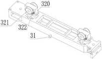
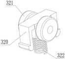
如图3所示,开关高度调节部32包括升降主体320、滑动轮321与一组伸缩弹簧322,升降主体320两侧均转动设置有滑动轮321,伸缩弹簧322连接设置于升降主体320与控制开关组件3之间,伸缩弹簧322位于升降主体320的中心位置。通过伸缩弹簧322来提供第一弹性压力。此结构设置所使用的零部件较少便于组装。As shown in FIG. 3 , the switch
如图4所示,开关高度调节部32包括升降主体320、一组滑动轮321与至少多组伸缩弹簧322,滑动轮321转动设置于升降主体320中部,多组伸缩弹簧322均布设置于升降主体320与控制开关组件3之间。此结构通过在升降主体320与控制开关组件3之间设置多组伸缩弹簧322来提高开关高度调节部32在被下压时提供更加的稳定均匀的弹性力。As shown in FIG. 4 , the switch
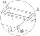
型材框柱10包括侧壁框柱,在侧壁框柱内部沿侧壁框柱的长度方向设有锁止筋条12,锁止筋条12上开设有开口向上的锁合槽口13,凸部锁舌31设置为一块状凸起,当此块状凸起向下穿入锁合槽口13中时实现锁止功能。此自锁机构中的凸部锁舌31和锁合槽口13便于加工制造,成本更加低廉。The
实施例三
如图12所示,同时,本发明还提供有一种内置百叶系统包括上述任一实施例中所提及的一种具有自锁功能的内置百叶开关机构,控制开关组件3包括翻页开关34与升降开关33,翻页开关34与翻页梯绳8相连接,升降开关33与升降梯绳7相连接。实现升降功能的传动绳的一端固定在转角组件4的底部,然后再绕过升降开关33中的升降滑轮45,接着再经过转角组件4中的换向滑轮46后,其另一端再穿过线架5后与百叶帘的升降梯绳7相连接,通过升降开关33的上下移动来实现百叶帘的升降。As shown in FIG. 12 , at the same time, the present invention also provides a built-in shutter system including a built-in shutter switch mechanism with a self-locking function mentioned in any of the above embodiments, and the
实现翻页功能的传动绳的两端分别固定连接在翻页开关34的上下两端,形成一个环形回路,在此环形回路中传动梯绳分别绕过转角组件4中的翻页轮42和固定在侧壁框柱底端的定滑轮47,由此通过移动翻页开关34可带动此环形回路转动,此时传动绳会带动翻页轮42转动,翻页轮42再带动固定在翻页轮42上的连接扁轴6转动,由此再带动绕接在连接扁轴6上的翻页梯绳8运动,由此可实现翻页动作。The two ends of the transmission rope that realizes the page-turning function are respectively fixedly connected to the upper and lower ends of the page-turning
实施例四
如图5与图11所示,本实施例四与实施例三的不同在于本实施例中的控制开关组件3设置为一体式启动开关35,启动开关35包括翻页控制部与升降控制部,翻页控制部与升降控制部与传动绳之间的绕线连接方式可参照实施例三的方式进行,另外翻页控制部通过传动绳与离合机构相连接,离合机构可及时将翻页轮42与扁轴连接器44进行分离与联合,由此可减少翻页梯绳8与线架5上的绕线轮之间的摩擦,从而延长翻页梯绳8的使用寿命。如图5所示,离合机构包括翻页轮42、涨缩弹簧43、扁轴连接器44以及安置座41,扁轴连接器44套设于翻页轮42上,涨缩弹簧43套设于翻页轮42上,涨缩弹簧43位于翻页轮42与扁轴连接器44之间,安置座41内设有限位凸块411,扁轴连接器44一侧端部固定有挡接片441,此挡接片441位于涨缩弹簧43的两组挡脚431之间,涨缩弹簧43处于正常状态时两组挡脚431不受力,涨缩弹簧43套设在翻页轮42上,涨缩弹簧43与翻页轮42之间为过度配合,由此涨缩弹簧43可随翻页轮42的转动而转动,并且再涨缩弹簧43上的挡脚431的限制下扁轴连接器44会一起随着翻页轮42进行转动,此时百叶帘进行翻页动作,当涨缩弹簧43的一组挡脚431被限位凸块411挡住时,由于翻页轮42的继续转动会使挡脚431因受到限位凸块411的挤压而使涨缩弹簧43处于松弛状态,也即为涨缩弹簧43的内径变大,此时涨缩弹簧43与翻页轮42之间为间隙配合,从而实现涨缩弹簧43与翻页轮42之间的分离,此时翻页轮42发生空转,此离合机构的设置可以防止连接扁轴6总是随着翻页轮42进行转动,由此也减少了翻页梯绳8与线架5之间的摩擦从而增加翻页梯绳8的使用寿命。As shown in FIG. 5 and FIG. 11 , the difference between the fourth embodiment and the third embodiment is that the
以实施例三并配合实施例二中的自锁机构为例对其工作原理进行如下介绍:首先将各部件安装至型材框柱10腔内部,然后将型材的上盖板11固定在型材框柱10上,上盖板11上设有滑轨,外控手柄21上设有滑块,使用时将滑块穿设在滑轨中,当外控手柄21上的磁体23靠近控制开关组件3上设置的磁体23时,由于磁力的吸引控制控制开关组件3上升第一距离,此时凸部锁舌31从锁止筋条12上的锁合槽口13中脱出解除锁定,由此控制开关组件3可以随着外控手柄21一起滑动,从而实现对百叶帘的升降和翻页,当需要锁止时,将控制开关组件3滑动至凸部锁舌31与锁合槽口13相对应的位置,然后将外控手柄21由滑轨中脱出,此时外控手柄21与控制开关组件3之间的磁力消失,在开关高度调节部32中的伸缩弹簧322的第一弹性压力的作用下控制开关组件3下降第一距离带动凸部锁舌31穿入锁止筋条12上的锁合槽口13中实现锁止功能。Taking the third embodiment and the self-locking mechanism in the second embodiment as an example, the working principle is introduced as follows: first, install the components into the cavity of the
上述说明是针对本发明较佳可行实施例的详细说明,但实施例并非用以限定本发明的专利申请范围,凡本发明所提示的技术精神下所完成的同等变化或修饰变更,均应属于本发明所涵盖专利范围。The above description is a detailed description of the preferred feasible embodiments of the present invention, but the embodiments are not intended to limit the scope of the patent application of the present invention. All equivalent changes or modifications completed under the technical spirit suggested by the present invention shall belong to This invention covers the scope of the patent.
Claims (10)
Translated fromChinesePriority Applications (1)
| Application Number | Priority Date | Filing Date | Title |
|---|---|---|---|
| CN202010895166.XACN112012641B (en) | 2020-08-31 | 2020-08-31 | Built-in shutter switch mechanism with self-locking function and built-in shutter system |
Applications Claiming Priority (1)
| Application Number | Priority Date | Filing Date | Title |
|---|---|---|---|
| CN202010895166.XACN112012641B (en) | 2020-08-31 | 2020-08-31 | Built-in shutter switch mechanism with self-locking function and built-in shutter system |
Publications (2)
| Publication Number | Publication Date |
|---|---|
| CN112012641Atrue CN112012641A (en) | 2020-12-01 |
| CN112012641B CN112012641B (en) | 2024-11-22 |
Family
ID=73504098
Family Applications (1)
| Application Number | Title | Priority Date | Filing Date |
|---|---|---|---|
| CN202010895166.XAActiveCN112012641B (en) | 2020-08-31 | 2020-08-31 | Built-in shutter switch mechanism with self-locking function and built-in shutter system |
Country Status (1)
| Country | Link |
|---|---|
| CN (1) | CN112012641B (en) |
Cited By (1)
| Publication number | Priority date | Publication date | Assignee | Title |
|---|---|---|---|---|
| CN115247531A (en)* | 2021-04-28 | 2022-10-28 | 亿丰综合工业股份有限公司 | Vertical blind |
Citations (5)
| Publication number | Priority date | Publication date | Assignee | Title |
|---|---|---|---|---|
| CN105064897A (en)* | 2015-07-17 | 2015-11-18 | 常熟中勤建材有限公司 | Venetian blind ascending and descending controller for double-layer hollow glass built-in window blind |
| CN109882061A (en)* | 2019-03-14 | 2019-06-14 | 无锡市纵横科技有限公司 | Lock control mechanism of built-in roller shutter insulating glass lifting magnetic control device |
| CN110318656A (en)* | 2019-08-09 | 2019-10-11 | 陈道云 | A kind of lockable mechanism of hollow louver glass window |
| CN209653911U (en)* | 2018-12-12 | 2019-11-19 | 余建文 | A kind of hollow louver glass window that can prevent blinds damage |
| CN213510367U (en)* | 2020-08-31 | 2021-06-22 | 无锡义永科技有限公司 | Built-in shutter opening and closing mechanism with self-locking function and built-in shutter system |
- 2020
- 2020-08-31CNCN202010895166.XApatent/CN112012641B/enactiveActive
Patent Citations (5)
| Publication number | Priority date | Publication date | Assignee | Title |
|---|---|---|---|---|
| CN105064897A (en)* | 2015-07-17 | 2015-11-18 | 常熟中勤建材有限公司 | Venetian blind ascending and descending controller for double-layer hollow glass built-in window blind |
| CN209653911U (en)* | 2018-12-12 | 2019-11-19 | 余建文 | A kind of hollow louver glass window that can prevent blinds damage |
| CN109882061A (en)* | 2019-03-14 | 2019-06-14 | 无锡市纵横科技有限公司 | Lock control mechanism of built-in roller shutter insulating glass lifting magnetic control device |
| CN110318656A (en)* | 2019-08-09 | 2019-10-11 | 陈道云 | A kind of lockable mechanism of hollow louver glass window |
| CN213510367U (en)* | 2020-08-31 | 2021-06-22 | 无锡义永科技有限公司 | Built-in shutter opening and closing mechanism with self-locking function and built-in shutter system |
Cited By (1)
| Publication number | Priority date | Publication date | Assignee | Title |
|---|---|---|---|---|
| CN115247531A (en)* | 2021-04-28 | 2022-10-28 | 亿丰综合工业股份有限公司 | Vertical blind |
Also Published As
| Publication number | Publication date |
|---|---|
| CN112012641B (en) | 2024-11-22 |
Similar Documents
| Publication | Publication Date | Title |
|---|---|---|
| US20100258253A1 (en) | Venetian blind | |
| US20140290876A1 (en) | Apparatus for a blind | |
| CN112012641A (en) | Built-in shutter opening and closing mechanism with self-locking function and built-in shutter system | |
| CN111956045A (en) | Electric curtain | |
| CN104234608B (en) | Upper open type roller shutter | |
| TWM340340U (en) | Braking device for gathering curtain | |
| WO2024174691A1 (en) | Roller shutter curtain | |
| CN213510367U (en) | Built-in shutter opening and closing mechanism with self-locking function and built-in shutter system | |
| KR101673490B1 (en) | Electromotive blind apparatus | |
| CN109882061A (en) | Lock control mechanism of built-in roller shutter insulating glass lifting magnetic control device | |
| CN106193975B (en) | A kind of roller shutter | |
| CN205297266U (en) | Can open book curtain formula (window) curtain of arbitrary size in optional position | |
| CN111364906A (en) | Hollow glass built-in shutter | |
| CN112641315B (en) | Device is used in design of intelligence house decoration | |
| JP3869649B2 (en) | Blind stopper device | |
| CN209817901U (en) | Lock control mechanism with built-in roller shutter hollow glass lifting magnetic control device | |
| CN212201839U (en) | Hollow glass built-in shutter | |
| CN213928179U (en) | A Magnetic Induction Controlled Insulating Glass Shutter | |
| CN217206220U (en) | Anti-falling structure for sunshade glass | |
| CN206386065U (en) | Sliding pin in hollow glass louver control | |
| US20200392783A1 (en) | Corded top down and cordless bottom up shade modification kit | |
| CN204410477U (en) | A kind of electronic Rome bar curtain rail | |
| CN221236663U (en) | Roller shutter head driving pull rod | |
| CN220141100U (en) | Lifting cabinet | |
| CN222414691U (en) | Magnetic drive curtain box and curtain |
Legal Events
| Date | Code | Title | Description |
|---|---|---|---|
| PB01 | Publication | ||
| PB01 | Publication | ||
| SE01 | Entry into force of request for substantive examination | ||
| SE01 | Entry into force of request for substantive examination | ||
| GR01 | Patent grant | ||
| GR01 | Patent grant |