CN112006691A - Knee joint replacement flexion-extension gap measurement balancing device - Google Patents
Knee joint replacement flexion-extension gap measurement balancing deviceDownload PDFInfo
- Publication number
- CN112006691A CN112006691ACN202010788634.3ACN202010788634ACN112006691ACN 112006691 ACN112006691 ACN 112006691ACN 202010788634 ACN202010788634 ACN 202010788634ACN 112006691 ACN112006691 ACN 112006691A
- Authority
- CN
- China
- Prior art keywords
- support plate
- flexion
- femoral condyle
- guide
- knee joint
- Prior art date
- Legal status (The legal status is an assumption and is not a legal conclusion. Google has not performed a legal analysis and makes no representation as to the accuracy of the status listed.)
- Granted
Links
Images


Classifications
- A—HUMAN NECESSITIES
- A61—MEDICAL OR VETERINARY SCIENCE; HYGIENE
- A61B—DIAGNOSIS; SURGERY; IDENTIFICATION
- A61B5/00—Measuring for diagnostic purposes; Identification of persons
- A61B5/103—Measuring devices for testing the shape, pattern, colour, size or movement of the body or parts thereof, for diagnostic purposes
- A61B5/107—Measuring physical dimensions, e.g. size of the entire body or parts thereof
- A61B5/1072—Measuring physical dimensions, e.g. size of the entire body or parts thereof measuring distances on the body, e.g. measuring length, height or thickness
- A—HUMAN NECESSITIES
- A61—MEDICAL OR VETERINARY SCIENCE; HYGIENE
- A61B—DIAGNOSIS; SURGERY; IDENTIFICATION
- A61B5/00—Measuring for diagnostic purposes; Identification of persons
- A61B5/103—Measuring devices for testing the shape, pattern, colour, size or movement of the body or parts thereof, for diagnostic purposes
- A61B5/107—Measuring physical dimensions, e.g. size of the entire body or parts thereof
- A61B5/1076—Measuring physical dimensions, e.g. size of the entire body or parts thereof for measuring dimensions inside body cavities, e.g. using catheters
Landscapes
- Health & Medical Sciences (AREA)
- Life Sciences & Earth Sciences (AREA)
- Biomedical Technology (AREA)
- Heart & Thoracic Surgery (AREA)
- Oral & Maxillofacial Surgery (AREA)
- Biophysics (AREA)
- Pathology (AREA)
- Engineering & Computer Science (AREA)
- Dentistry (AREA)
- Physics & Mathematics (AREA)
- Medical Informatics (AREA)
- Molecular Biology (AREA)
- Surgery (AREA)
- Animal Behavior & Ethology (AREA)
- General Health & Medical Sciences (AREA)
- Public Health (AREA)
- Veterinary Medicine (AREA)
- Prostheses (AREA)
Abstract
Description
Translated fromChinese技术领域technical field
本发明涉及关节外科手术工具,具体是一种膝关节置换屈伸间隙测量平衡装置。The invention relates to a joint surgical tool, in particular to a flexion-extension gap measurement balance device for knee joint replacement.
背景技术Background technique
全膝关节置换术中伸屈间隙平衡是手术成功的关键,目前绝大多数术者均采用测量截骨法利用股骨解剖标志线进行股骨后髁截骨,这种方法不能准确的反映伸屈间隙及膝关节内外侧的软组织张力,术后容易导致屈曲间隙大于伸直间隙,并且导致内外侧间隙张力不平衡,从而引起术后关节不稳,导致手术失败。而间隙平衡装置则可尽可能的避免上述情况出现。The balance of extension and flexion gap in total knee arthroplasty is the key to the success of the operation. At present, the vast majority of operators use the measurement osteotomy method to perform posterior femoral condyle osteotomy using the femoral anatomical landmark line. This method cannot accurately reflect the extension and flexion gap. The soft tissue tension on the medial and lateral sides of the knee joint is likely to cause the flexion gap to be larger than the extension gap after surgery, and lead to unbalanced tension between the medial and lateral gaps, resulting in postoperative joint instability and failure of the operation. The gap balancing device can avoid the above situation as much as possible.
一个稳定的人工膝关节的伸屈间隙及伸屈间隙以及伸屈间隙的内外侧张力均应平衡。目前全膝关节置换术中常规用spacer联合力线杆进行伸直间隙的平衡。这种方法仅可保证伸直间隙为等宽矩形,并不能测量及调整伸直间隙的内外侧张力。测量截骨法的进行,需要利用抱髁器及股骨远端三条解剖标志线-whiteside’s线、通髁线以及后髁连线确定后髁截骨量,即屈曲间隙大小。但该方法有太多的不确定性:首先,三条解剖标志线的个体差异性很大;其次,每个手术医生确定的三条解剖标志线存在主观差异;再次,根据该方法进行截骨时不能确定屈曲间隙的大小,从而不能保证截骨后的屈曲间隙和伸直间隙相同,亦无法保证屈曲间隙的内外侧张力相等。A stable artificial knee joint should balance the extension and flexion gap and the medial and lateral tension of the extension and flexion gap. Currently in total knee arthroplasty, spacer joint force line rods are routinely used to balance the extension gap. This method can only ensure that the straightening gap is a rectangle of equal width, and cannot measure and adjust the inner and outer tension of the straightening gap. To measure the osteotomy, the amount of posterior condyle osteotomy, that is, the size of the flexion gap, needs to be determined using the condylar embracing device and three anatomical landmarks at the distal end of the femur—whiteside’s line, transcondylar line, and posterior condyle connecting line. However, this method has too many uncertainties: first, the individual differences of the three anatomical landmarks are very large; secondly, there are subjective differences in the three anatomical landmarks determined by each surgeon; thirdly, the osteotomy cannot be performed according to this method. Determine the size of the flexion gap, so that the flexion gap and extension gap after osteotomy cannot be guaranteed to be the same, nor can the inner and outer tension of the flexion gap be equal.
综上所述,目前的全膝关节伸直间隙及屈曲间隙截骨法,无法准确获得相等屈伸间隙,也无法获得内外侧等张的伸屈间隙。In conclusion, the current total knee joint extension gap and flexion gap osteotomy methods cannot accurately obtain equal flexion-extension gaps, and cannot obtain medial and lateral isotonic extension-flexion gaps.
发明内容SUMMARY OF THE INVENTION
本发明的目的在于克服现有技术的不足,解决膝关节间隙测量难、平衡不方便的问题。The purpose of the present invention is to overcome the deficiencies of the prior art and solve the problems of difficult knee joint clearance measurement and inconvenient balance.
为达到上述发明目的,提供一种膝关节置换屈伸间隙测量平衡装置,包括轴向带刻度的连接定位轴、U形的移动胫骨平台托板、U形的固定股骨髁托板;In order to achieve the above-mentioned purpose of the invention, a knee joint replacement flexion-extension gap measurement balance device is provided, which includes an axially scaled connection positioning shaft, a U-shaped movable tibial platform support plate, and a U-shaped fixed femoral condyle support plate;
所述连接定位轴表面沿轴向布设棘齿;所述连接定位轴的顶端设孔;Ratchet teeth are arranged on the surface of the connection and positioning shaft along the axial direction; holes are arranged at the top of the connection and positioning shaft;
所述移动胫骨平台托板的U形底部板面中设供连接定位轴穿入的开口;所述移动胫骨平台托板上还设有贯通至所述开口内壁的开窗I,所述开窗I中铰接配合棘齿的棘爪中部;所述棘爪的顶端用于抵靠所述棘齿,所述棘爪的尾端通过弹簧连接至所述移动胫骨平台托板;In the U-shaped bottom plate surface of the described mobile tibial platform support plate, there is an opening for connecting the positioning shaft to penetrate; the mobile tibial platform support plate is also provided with a window I that is passed through to the inner wall of the opening, and the window opening The middle part of the pawl of the ratchet tooth is hingedly matched in I; the top end of the pawl is used to abut the ratchet tooth, and the tail end of the pawl is connected to the movable tibial plateau support plate through a spring;
所述固定股骨髁托板的U形底部朝向一侧设用于固定至孔的连接轴,所述连接轴上设用于与所述孔紧配合的膨胀块。The U-shaped bottom of the fixed femoral condyle support plate faces one side and is provided with a connecting shaft for being fixed to the hole, and an expansion block for tightly fitting with the hole is provided on the connecting shaft.
本处所指的移动胫骨平台托板和固定股骨髁托板均呈U形构造,其中U形同一顶部的两支分叉位于同一平面用于承托对应部位。所述移动胫骨平台托板连接后的承托面和所述固定股骨髁托板连接后的的承托面大致垂直于所述连接定位轴。所述固定股骨髁托板的U形的底部与连接定位轴通过连接轴和孔的配合连接。棘齿和棘爪配合时,能阻挡移动胫骨平台托板朝向连接定位轴顶端移动。所述膨胀块通过在孔内膨胀,使得连接轴在连接定位轴上相对定位,一般可以采用弹性金属圈套箍的形式。Both the mobile tibial plateau support plate and the fixed femoral condyle support plate referred to here are U-shaped structures, in which the two bifurcations at the same top of the U-shape are located on the same plane to support the corresponding parts. The connecting bearing surface of the movable tibial platform support plate and the connecting bearing surface of the fixed femoral condyle support plate are substantially perpendicular to the connection positioning axis. The U-shaped bottom of the fixed femoral condyle support plate is connected with the connection positioning shaft through the cooperation of the connection shaft and the hole. When the ratchet teeth and the pawls cooperate, they can block the moving tibial platform support plate from moving toward the top of the connecting positioning shaft. The expansion block is expanded in the hole so that the connecting shaft is relatively positioned on the connecting and positioning shaft, generally in the form of an elastic metal ring ferrule.
优选的,所述连接定位轴的侧壁表面沿轴向布设有齿;所述移动胫骨平台托板上还设有贯通至所述开口内壁的开窗II,所述开窗II中设转轴,所述转轴上同轴固定与齿啮合的齿轮;所述转轴穿出所述移动胫骨平台托板侧面,并在穿出端设用于对转轴施加旋转力的卡头。Preferably, teeth are arranged on the side wall surface of the connecting and positioning shaft in the axial direction; the movable tibial platform support plate is also provided with a window II that penetrates to the inner wall of the opening, and a rotating shaft is arranged in the window II. A gear meshing with the teeth is coaxially fixed on the rotating shaft; the rotating shaft passes through the side surface of the movable tibial platform support plate, and a chuck for applying a rotational force to the rotating shaft is provided at the passing end.
本处所指的齿轮通过在齿上啮合并移动,带动移动胫骨平台托板沿着连接定位轴移动。所述卡头配套有扳手,一般采用扭力扳手,通过在移动胫骨平台托板外操作扳手驱动转轴形成旋转,能省力地带动齿轮在齿上的移动。The gear referred to here drives the moving tibial plateau support plate to move along the connecting and positioning shaft by engaging and moving on the teeth. The clamp head is equipped with a wrench, generally a torque wrench is used, and the rotation of the shaft is driven by operating the wrench outside the moving tibial platform support plate, which can drive the movement of the gear on the teeth in a labor-saving manner.
优选的,所述开口内壁还固定有导向结构;所述连接定位轴的侧壁表面沿轴向设配合导向结构的导轨。Preferably, a guide structure is also fixed on the inner wall of the opening; a guide rail matching the guide structure is arranged on the side wall surface of the connecting and positioning shaft along the axial direction.
本处所指的导向结构,可以是凸块、凹槽等形式,导向结构与导轨的配合使得移动胫骨平台托板能沿连接定位轴移动的同时,避免旋转滑脱。The guide structure referred to here can be in the form of a bump, a groove, etc. The cooperation of the guide structure and the guide rail enables the moving tibial platform support plate to move along the connection and positioning axis while avoiding rotation and slippage.
优选的,所述固定股骨髁托板朝向另一侧竖立有导向块,所述导向块开设朝向股骨髁截骨板安装部位的钻头导向孔。Preferably, a guide block is erected toward the other side of the fixed femoral condyle support plate, and the guide block defines a drill guide hole facing the installation site of the femoral condyle osteotomy plate.
本处所指的钻头导向孔贯穿所述导向块,当平衡装置设置到位后,通过在钻头导向孔中穿入钻头,从而得以在股骨髁上精确打孔。The drill bit guide hole referred to here runs through the guide block, and after the balancing device is set in place, the drill bit is inserted into the drill bit guide hole so as to accurately drill holes on the femoral condyle.
优选的,还包括偏心导轮,所述导向块包括与固定股骨髁托板固定的导向板及其上套设的外套;所述外套的侧壁中穿设所述偏心导轮的轮体;所述导向板中开设垂直于连接定位轴的长圆孔,所述偏心导轮的心轴穿设在所述长圆孔中;所述外套与导向板之间还设置有锁定机构;所述钻头导向孔设置于所述外套。Preferably, an eccentric guide wheel is also included, and the guide block includes a guide plate fixed with a fixed femoral condyle support plate and a jacket sleeved thereon; a wheel body of the eccentric guide wheel is worn in the side wall of the jacket; The guide plate is provided with an oblong hole perpendicular to the connecting and positioning shaft, and the mandrel of the eccentric guide wheel is inserted into the oblong hole; a locking mechanism is also arranged between the outer sleeve and the guide plate; the drill bit guides A hole is provided in the jacket.
本处所指垂直于连接定位轴的长圆孔,是指长圆孔的长度方向垂直于连接定位轴的轴线。一般地,偏心导轮可以为一体制造,保证其整体性和强度,本处所指的偏心导轮一般可由轮体和心轴组成,其心轴平行于轮体的轴心,当轮体旋转时,心轴绕轮体轴心旋转。本处所指的锁定机构可以是穿过外套顶靠至导向板的螺栓、磁吸固定等形式,能够方便地将外套与导向板进行锁紧固定和解锁。The oblong hole that is perpendicular to the connection and positioning axis here means that the length direction of the oblong hole is perpendicular to the axis of the connection and positioning axis. In general, the eccentric guide wheel can be manufactured as a whole to ensure its integrity and strength. The eccentric guide wheel referred to here can generally be composed of a wheel body and a mandrel, and its mandrel is parallel to the axis of the wheel body. When the wheel body rotates , the mandrel rotates around the axis of the wheel body. The locking mechanism referred to here can be in the form of bolts that pass through the outer casing against the guide plate, magnetic attraction fixing, etc., which can conveniently lock, fix and unlock the outer casing and the guide plate.
优选的,所述导向板的板面设凸块,所述凸块穿出外套的侧壁,所述凸块表面绘制与外套侧壁相对应的标度。Preferably, the surface of the guide plate is provided with bumps, the bumps protrude out of the side walls of the outer casing, and the scales corresponding to the side walls of the outer casing are drawn on the surfaces of the bumps.
本处所指的凸块能在外套外被直观的观察。当微调钻头导向孔位置时,凸块上的标度会相对外套侧壁移动。标度设置的具体形式,可以是凸块上设刻度,对应外套侧壁设刻度针,也可以凸块上设刻度针,对应外套侧壁设刻度。The bumps referred to here can be visually observed outside the jacket. When fine-tuning the position of the drill pilot hole, the scale on the boss moves relative to the sidewall of the housing. The specific form of the scale setting can be that a scale is set on the convex block, and a scale needle is set corresponding to the side wall of the jacket, or a scale needle is set on the convex block, and a scale is set corresponding to the side wall of the casing.
优选的,所述导向块上连接有用于穿入股骨的髓内杆。Preferably, an intramedullary rod for penetrating the femur is connected to the guide block.
优选的,所述导向块设平行于连接定位轴的导向槽;所述髓内杆的一端固定圆柱形的滑块,所述滑块滑设于所述导向槽内。Preferably, the guide block is provided with a guide groove parallel to the connection positioning shaft; one end of the intramedullary rod is fixed with a cylindrical slider, and the slider is slidably arranged in the guide groove.
本处所指的导向槽与圆柱形的滑块配合,其槽截面造型为适应圆柱形壁面的弧形,所述髓内杆从导向槽的开口面伸出。The guide groove referred to here is matched with a cylindrical slide block, and the groove cross section is shaped to fit the arc shape of the cylindrical wall surface, and the intramedullary rod protrudes from the opening surface of the guide groove.
优选的,所述固定股骨髁托板的U形底部与所述连接轴通过铰链连接;所述铰链的轴延伸线与所述固定股骨髁托板的U形中轴线共线。Preferably, the U-shaped bottom of the fixed femoral condyle support plate and the connecting shaft are connected by a hinge; the axis extension line of the hinge is collinear with the U-shaped central axis of the fixed femoral condyle support plate.
本处所指的固定股骨髁托板的U形底部的铰接轴位置两侧还可以凸设有用于阻挡固定股骨髁托板过度旋转的挡块。所述固定股骨髁托板在中轴线两侧对称。The two sides of the hinge shaft position of the U-shaped bottom of the fixed femoral condyle support plate referred to here may also be protruded with blocks for blocking the excessive rotation of the fixed femoral condyle support plate. The fixed femoral condyle support plate is symmetrical on both sides of the central axis.
优选的,所述连接轴顶部延伸出指针;所述固定股骨髁托板上竖立用于标示指针与所述固定股骨髁托板角度的刻度盘。Preferably, a pointer extends from the top of the connecting shaft; a dial for marking the angle between the pointer and the fixed femoral condyle support plate is erected on the fixed femoral condyle support plate.
本处所指的指针能沿铰接轴摆动。The pointer referred to here can swing along the hinge axis.
优选的,所述固定股骨髁托板上竖立标尺,所述标尺上设用于贴靠股骨前髁皮质的滑尺。Preferably, a ruler is erected on the fixed femoral condyle support plate, and the ruler is provided with a sliding ruler for abutting against the cortex of the anterior femoral condyle.
所述滑尺沿标尺滑动,测量时,由远及近抵靠至股骨前髁皮质,观察标尺能方便地读取出滑尺移动的距离,从而得出股骨髁的前髁厚度。The sliding scale slides along the scale, and when measuring, it touches the cortex of the anterior condyle of the femur from far to near, and observing the scale can easily read the moving distance of the sliding scale, thereby obtaining the thickness of the anterior condyle of the femoral condyle.
通过调节移动胫骨平台托板和固定股骨髁托板的间距,实现手术时对胫骨平台与股骨髁之间间隙的调整。操作时将平衡装置安装到位,滑动移动胫骨平台托板即可张开间隙,需要回收平衡装置时,调节棘爪的状态即可在人体软组织的压力下自然放松平衡装置。通过将移动胫骨平台托板在连接定位轴向上方单向移动,在达到目标状态后停止移动,此时连接定位轴上所显示的刻度,即为当前张力下间隙的大小。而采用膨胀块配合孔的形式,则便于固定股骨髁托板的替换。By adjusting the distance between the movable tibial plateau support plate and the fixed femoral condyle support plate, the gap between the tibial plateau and the femoral condyle can be adjusted during surgery. During operation, install the balance device in place, slide and move the tibial platform support plate to open the gap, and when the balance device needs to be recovered, adjust the state of the pawl to naturally relax the balance device under the pressure of human soft tissue. By moving the movable tibial platform support plate in one direction above the connection and positioning axis, and stop moving after reaching the target state, the scale displayed on the connection and positioning axis at this time is the size of the gap under the current tension. The use of the form of the expansion block with the hole is convenient for the replacement of the fixed femoral condyle support plate.
通过齿轮与齿的配合,使得移动胫骨平台托板的移动和调整更加精确化。通过旋转卡头,能方便地转动齿轮;配合扭力扳手后,更能保证平衡装置提供特定的张拉力,避免对人体造成损伤。Through the cooperation of gears and teeth, the movement and adjustment of the moving tibial plateau support plate are more precise. By rotating the chuck, the gear can be easily rotated; after the torque wrench is used, the balance device can provide a specific tension force to avoid damage to the human body.
通过穿入钻头导向孔后对股骨髁进行打孔,从而便于在股骨髁上精确配置截骨板。The femoral condyle is drilled after penetrating the drill pilot hole, which facilitates the precise placement of the osteotomy plate on the femoral condyle.
所述偏心导轮的心轴通过在长圆孔的长轴中往复移动,从而带动外套形成平行于连接定位轴的往复移动,便于对钻头导向孔位置的微调。The mandrel of the eccentric guide wheel reciprocates in the long axis of the oblong hole, thereby driving the outer sleeve to form a reciprocating movement parallel to the connection and positioning axis, which is convenient for fine-tuning the position of the drill guide hole.
通过标度的设置,能直观地显示出外套相对导向板的移动方向和距离,从而便于识别微调的幅度。Through the setting of the scale, the moving direction and distance of the jacket relative to the guide plate can be displayed intuitively, so as to facilitate the identification of the fine-tuning range.
通过髓内杆的设置,增加了平衡装置的轴向稳定性,在撑开间隙时平衡装置难以发生移位,避免截骨定位出现偏差。The arrangement of the intramedullary rod increases the axial stability of the balance device, and it is difficult for the balance device to be displaced when the gap is opened, thereby avoiding deviation in the positioning of the osteotomy.
所述髓内杆在圆柱形滑块的作用下,能在导向槽内滑动,提升了髓内杆对不同股骨尺寸的适应性。导向槽因为有沿口的限制,也让髓内杆在能够沿圆柱形滑块周向旋转的同时,避免髓内杆在导向槽内过度转动。The intramedullary rod can slide in the guide groove under the action of the cylindrical slider, which improves the adaptability of the intramedullary rod to different femur sizes. Because the guide groove is limited by the bezel, the intramedullary rod can also rotate in the circumferential direction of the cylindrical slider while avoiding excessive rotation of the intramedullary rod in the guide groove.
通过固定股骨髁托板与连接轴之间的铰接,允许固定股骨髁托板相对连接轴形成一定的摆动。Through the hinge between the fixed femoral condyle support plate and the connecting shaft, the fixed femoral condyle support plate is allowed to form a certain swing relative to the connecting shaft.
通过对照指针和刻度盘,观察指针摆动即可实现固定股骨髁托板旋转幅度和方向的测量,以便直观地观察伸直间隙的内外侧平衡情况。By comparing the pointer and the dial, the rotation amplitude and direction of the fixed femoral condyle support plate can be measured by observing the swing of the pointer, so as to visually observe the inner and outer balance of the extension gap.
通过标尺和滑尺的配合,依据股骨髁的前髁厚度,能方便地选择合适大小的股骨假体。Through the cooperation of the ruler and the sliding ruler, according to the thickness of the anterior condyle of the femoral condyle, the appropriate size of the femoral prosthesis can be easily selected.
本发明的有益效果是能方便地测量和平衡关节间隙,便于全膝置换术的进行。The beneficial effect of the invention is that the joint space can be easily measured and balanced, and the total knee replacement operation can be carried out conveniently.
附图说明Description of drawings
图1为本发明的间隙测量平衡装置拆卸下固定股骨髁托板后的示意图;1 is a schematic diagram of the gap measurement balance device of the present invention after disassembling and fixing the femoral condyle support plate;
图2为本发明的间隙测量平衡装置第一种实施例整体示意图;Fig. 2 is the overall schematic diagram of the first embodiment of the gap measurement balance device of the present invention;
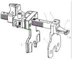
图3为本发明的间隙测量平衡装置第二种实施例安装爆炸图;3 is an exploded view of the installation of the second embodiment of the gap measurement balance device of the present invention;
其中:in:
1-连接定位轴 11-刻度 12-棘齿1-Connect the positioning shaft 11-Scale 12-Ratchet
13-孔 14-齿 2-移动胫骨平台托板13-Hole 14-Tooth 2-Mobile Tibial Plateau Plate
21-开窗I 22-棘爪 23-开窗II21-Window I 22-Pawl 23-Window II
24-转轴 25-齿轮 26-卡头24-shaft 25-gear 26-chuck
3-固定股骨髁托板 31-连接轴 32-膨胀块3-Fixed femoral condyle plate 31-Connected shaft 32-Expansion block
33-钻头导向孔 34-偏心导轮 341-轮体33- Drill guide hole 34- Eccentric guide wheel 341- Wheel body
342-心轴 35-导向板 351-长圆孔342-Spindle 35-Guide plate 351-Slotted hole
352-凸块 353-导向槽 36-外套352-Bump 353-Guide groove 36-Outer
37-指针 38-刻度盘 4-髓内杆37-Pointer 38-Dial 4-Intramedullary rod
41-滑块 5-铰链 6-标尺41-Slider 5-Hinge 6-Ruler
61-滑尺61-Slide Ruler
具体实施方式Detailed ways
以下结合附图和具体实施例,对本发明做进一步说明。The present invention will be further described below with reference to the accompanying drawings and specific embodiments.
根据图1至图3所示的一种膝关节置换屈伸间隙测量平衡装置,包括轴向带刻度11的连接定位轴1、U形的移动胫骨平台托板2、U形的固定股骨髁托板3;所述连接定位轴1表面沿轴向布设棘齿12;所述连接定位轴1的顶端设孔13;所述移动胫骨平台托板2的U形底部板面中设供连接定位轴1穿入的开口;所述移动胫骨平台托板2上还设有贯通至所述开口内壁的开窗I21,所述开窗I21中铰接配合棘齿12的棘爪22中部;所述棘爪(22)的顶端用于抵靠所述棘齿(12),所述棘爪(22)的尾端通过弹簧连接至所述移动胫骨平台托板(2);所述固定股骨髁托板3的U形底部朝向一侧设用于固定至孔13的连接轴31,所述连接轴31上设用于与所述孔13紧配合的膨胀块32。A knee joint replacement flexion-extension gap measurement balance device shown in Fig. 1 to Fig. 3 includes a connecting and positioning shaft 1 with an
所述连接定位轴1的侧壁表面沿轴向布设有齿14;所述移动胫骨平台托板2上还设有贯通至所述开口内壁的开窗II23,所述开窗II23中设转轴24,所述转轴24上同轴固定与齿14啮合的齿轮25;所述转轴24穿出所述移动胫骨平台托板2侧面,并在穿出端设用于对转轴24施加旋转力的内六角卡头26。A
所述固定股骨髁托板3的U形底部与所述连接轴31通过铰链5连接;所述铰链5的轴延伸线与所述固定股骨髁托板3的U形中轴线共线。The U-shaped bottom of the fixed femoral condyle support plate 3 is connected with the connecting
根据图1至2所示的一种膝关节置换屈伸间隙测量平衡装置第一种实施例,所述连接轴31顶部延伸出指针37;所述固定股骨髁托板3上竖立用于标示指针37与所述固定股骨髁托板3角度的刻度盘38。According to the first embodiment of a knee joint replacement flexion-extension gap measurement balance device shown in FIGS. 1 to 2 , a
根据图1和图3所示的一种膝关节置换屈伸间隙测量平衡装置第二种实施例,所述固定股骨髁托板3朝向另一侧竖立有导向块,所述导向块开设朝向股骨髁截骨板安装部位的钻头导向孔33。还包括偏心导轮34,所述导向块包括与固定股骨髁托板3固定的导向板35及其上套设的外套36;所述外套36的侧壁中穿设所述偏心导轮34的轮体341;所述导向板35中开设垂直于连接定位轴1的长圆孔351,所述偏心导轮34的心轴342穿设在所述长圆孔中351;所述外套36与导向板35之间还设置有锁定机构;所述钻头导向孔33设置于所述外套36。所述导向板35的板面设凸块352,所述凸块352穿出外套36的侧壁,所述凸块352表面绘制与外套36侧壁相对应的标度。所述导向块的导向板35上连接有用于穿入股骨的髓内杆4,所述导向块设平行于连接定位轴1的导向槽353;所述髓内杆4的一端固定圆柱形的滑块41,所述滑块41滑设于所述导向槽353内。所述固定股骨髁托板3的导向板35上竖立标尺6,所述标尺6上设用于贴靠股骨前髁皮质的滑尺61。According to the second embodiment of a knee joint replacement flexion-extension gap measurement balance device shown in FIG. 1 and FIG. 3 , the fixed femoral condyle support plate 3 is erected with a guide block facing the other side, and the guide block is opened toward the femoral condyle. The drill guide hole 33 at the installation site of the osteotomy plate. Also includes an
间隙测量平衡装置在膝关节置换手术中的使用流程:The use of the gap measurement balance device in knee replacement surgery:
第一部分:伸直间隙的测量,采用第一种实施例中的间隙测量平衡装置The first part: the measurement of the straightening gap, using the gap measurement balance device in the first embodiment
测量伸直间隙时,需完成股骨远端及胫骨平台截骨,股骨远端及胫骨平台是平整骨面,便于间隙平衡装置的托板安放。When measuring the extension gap, it is necessary to complete the osteotomy of the distal femur and the tibial plateau. The distal femur and the tibial plateau are flat bone surfaces, which are convenient for the placement of the support plate of the gap balance device.
先伸直膝关节,关节间隙内插入组装好的移动胫骨平台托板2、固定股骨髁托板3。托板的U型间隙供后交叉韧带穿过。连接定位轴1上移动胫骨平台托板2对应的初始刻度为零。Straighten the knee joint first, insert the assembled mobile tibial platform support plate 2 and fixed femoral condyle support plate 3 into the joint space. The U-shaped gap of the pallet is for the passage of the posterior cruciate ligament. The initial scale corresponding to the movement of the tibial plateau support plate 2 on the connection and positioning shaft 1 is zero.
采用扭力扳手旋转卡头26,直至达到30至40磅扭力(此张力接近膝关节伸直状态韧带自然张力),记录连接定位轴1指示的刻度值I。此时可以测量出截骨后股骨前髁平面截骨面至胫骨平台截骨面的宽度,可以方便地计算出所需假体匹配的垫片厚度。Use a torque wrench to rotate the
再观察指针37所指偏转角度,若指针37所指角度为0,则表示股骨远端截骨面和胫骨平台截骨面相平行。若指针37所指角度不为零,则应将器械取出,根据角度偏移方向对膝关节内侧软组织或外侧软组织进行松解,松解后再次放入器械,以相同扭力撑开间隙,观察指针37所指角度。循环上述步骤直至指针37指向零刻度,此时内外侧软组织张力平衡,股骨远端截骨面和胫骨平台截骨面相平行。Then observe the deflection angle pointed by the
记录连接定位轴1上的伸直间隙测量值,取出器械。Record the measurement of the extension gap on the connecting axis 1 and remove the instrument.
第二部分:屈曲间隙的测量,采用第二种实施例中的间隙测量平衡装置Part II: Measurement of buckling gap, using the gap measurement balance device in the second embodiment
将膝关节屈曲90°,将髓内杆4沿股骨髓腔插入股骨,髓内杆4通过在导向槽353内上下活动,以适应不同大小的股骨前后轴。同时在关节间隙内插入组装好的移动胫骨平台托板2、固定股骨髁托板3。托板的U型间隙供后交叉韧带穿过。所有刻度初始刻度回归初始值。The knee joint is flexed 90°, and the intramedullary rod 4 is inserted into the femur along the femoral medullary cavity. The intramedullary rod 4 moves up and down in the
采用扭力扳手旋转卡头26,直至达到之前伸直间隙所使用扭力大小。记录连接定位轴1指示的刻度值II。若刻度值II与刻度值I相同,则表明在同等张力情况下,伸直间隙与屈曲间隙相等,不需要再进行调整。此时,股骨已完成外旋角度自动定位,即可进行股骨髁四合一截骨板定位孔打孔。截骨后屈曲间隙内外侧张力相等,且屈曲间隙与伸直间隙相同。Use a torque wrench to rotate the
若刻度值II数值大于或小于刻度值I,则应通过旋转偏心导轮(34)调整标度指示的刻度值III,向下或向下移动钻头导向孔33,以使刻度值III和刻度值II数值总和等于刻度值I。此时,股骨已完成外旋角度自动定位,即可进行股骨髁四合一截骨板定位孔打孔。截骨后屈曲间隙内外侧张力相等,且屈曲间隙与伸直间隙相同。If the scale value II is larger or smaller than the scale value I, the scale value III indicated by the scale should be adjusted by rotating the eccentric guide wheel (34), and the drill guide hole 33 should be moved downward or downward to make the scale value III and scale value The sum of the II values is equal to the scale value I. At this point, the automatic positioning of the external rotation angle of the femur has been completed, and the positioning hole of the femoral condyle four-in-one osteotomy plate can be drilled. After osteotomy, the tension between the inside and outside of the flexion gap is equal, and the flexion gap is the same as the extension gap.
调整完成后取出器械,按照定位孔位置安装股骨髁四合一截骨板,进行股骨髁截骨。After the adjustment is completed, take out the instrument, install the femoral condyle four-in-one osteotomy plate according to the position of the positioning hole, and perform the femoral condyle osteotomy.
该方案相对现有膝关节置换手术设备的优势:The advantages of this solution over existing knee replacement surgical equipment:
现有技术中的具有类似功能的抱髁器,是利用股骨的解剖标志进行股骨外旋角的设定,其屈曲间隙截骨与伸直间隙无关,且截骨后需进行屈曲间隙软组织平衡。而相对地,本方案的间隙测量平衡装置:1.不以解剖标志进行定位,避免可个体差异以及术者的主观感受差异;2.屈曲间隙截骨时根据胫骨近端截骨面为参考,平行胫骨骨面行股骨外旋截骨,股骨外旋角度根据张力进行自动定位,截骨后可保证屈伸、内外侧间隙平衡;3.截骨后伸屈间隙为等宽矩形,内外侧韧带张力相等。The condyle embracing device with similar functions in the prior art uses the anatomical landmarks of the femur to set the external rotation angle of the femur. On the other hand, the gap measurement balance device of this scheme: 1. Do not use anatomical landmarks for positioning, to avoid individual differences and differences in the operator's subjective feeling; 2. The proximal tibia osteotomy surface is used as a reference for flexion gap osteotomy. The femoral external rotation osteotomy is performed parallel to the tibial surface, and the femoral external rotation angle is automatically positioned according to the tension. After the osteotomy, the balance of flexion and extension, medial and lateral gaps can be ensured. equal.
以上已对本发明创造的较佳实施例进行了具体说明,但本发明创造并不限于所述的实施例,熟悉本领域的技术人员在不违背本发明创造精神的前提下还可以作出种种的等同的变型或替换,这些等同变型或替换均包含在本申请权利要求所限定的范围内。The preferred embodiments of the present invention have been specifically described above, but the present invention is not limited to the described embodiments. Those skilled in the art can also make various equivalents without departing from the spirit of the present invention. Modifications or substitutions of the present application, these equivalent modifications or substitutions are all included within the scope defined by the claims of the present application.
Claims (10)
Translated fromChinesePriority Applications (1)
| Application Number | Priority Date | Filing Date | Title |
|---|---|---|---|
| CN202010788634.3ACN112006691B (en) | 2020-08-07 | 2020-08-07 | Knee joint replacement flexion-extension gap measurement balancing device |
Applications Claiming Priority (1)
| Application Number | Priority Date | Filing Date | Title |
|---|---|---|---|
| CN202010788634.3ACN112006691B (en) | 2020-08-07 | 2020-08-07 | Knee joint replacement flexion-extension gap measurement balancing device |
Publications (2)
| Publication Number | Publication Date |
|---|---|
| CN112006691Atrue CN112006691A (en) | 2020-12-01 |
| CN112006691B CN112006691B (en) | 2024-01-23 |
Family
ID=73498785
Family Applications (1)
| Application Number | Title | Priority Date | Filing Date |
|---|---|---|---|
| CN202010788634.3AActiveCN112006691B (en) | 2020-08-07 | 2020-08-07 | Knee joint replacement flexion-extension gap measurement balancing device |
Country Status (1)
| Country | Link |
|---|---|
| CN (1) | CN112006691B (en) |
Cited By (4)
| Publication number | Priority date | Publication date | Assignee | Title |
|---|---|---|---|---|
| CN112754594A (en)* | 2021-01-21 | 2021-05-07 | 北京力达康科技有限公司 | Single-side lead screw adjusting type bone cutting device for femoral condyle |
| CN112754595A (en)* | 2021-01-21 | 2021-05-07 | 北京力达康科技有限公司 | Single-side eccentric adjustment type osteotomy device for femoral condyle |
| CN115040265A (en)* | 2022-05-31 | 2022-09-13 | 北京市春立正达医疗器械股份有限公司 | A knee joint space balancer |
| CN115040266A (en)* | 2022-05-31 | 2022-09-13 | 北京市春立正达医疗器械股份有限公司 | Knee joint knee bending gap balancer |
Citations (7)
| Publication number | Priority date | Publication date | Assignee | Title |
|---|---|---|---|---|
| US20040122441A1 (en)* | 2002-12-09 | 2004-06-24 | Zimmer Kabushiki Kaisha | Measuring apparatus for total knee replacement operation |
| CN103519818A (en)* | 2013-10-22 | 2014-01-22 | 山东大学齐鲁医院 | Knee-joint gap balance tester |
| CN204797805U (en)* | 2015-07-06 | 2015-11-25 | 微创骨科医疗科技(苏州)有限公司 | Balanced measuring device of knee joint soft tissue |
| CN107106189A (en)* | 2014-11-19 | 2017-08-29 | 捷迈有限公司 | Gap calibration femur measuring appliance |
| CN107693065A (en)* | 2017-11-07 | 2018-02-16 | 北京蒙太因医疗器械有限公司 | Knee space retractor |
| US20200155134A1 (en)* | 2018-11-15 | 2020-05-21 | Little Engine, LLC | Knee flexion and extension gap tensioning and measuring apparatus |
| CN213821413U (en)* | 2020-08-07 | 2021-07-30 | 徐卫东 | Knee joint replacement surgery caliber |
- 2020
- 2020-08-07CNCN202010788634.3Apatent/CN112006691B/enactiveActive
Patent Citations (7)
| Publication number | Priority date | Publication date | Assignee | Title |
|---|---|---|---|---|
| US20040122441A1 (en)* | 2002-12-09 | 2004-06-24 | Zimmer Kabushiki Kaisha | Measuring apparatus for total knee replacement operation |
| CN103519818A (en)* | 2013-10-22 | 2014-01-22 | 山东大学齐鲁医院 | Knee-joint gap balance tester |
| CN107106189A (en)* | 2014-11-19 | 2017-08-29 | 捷迈有限公司 | Gap calibration femur measuring appliance |
| CN204797805U (en)* | 2015-07-06 | 2015-11-25 | 微创骨科医疗科技(苏州)有限公司 | Balanced measuring device of knee joint soft tissue |
| CN107693065A (en)* | 2017-11-07 | 2018-02-16 | 北京蒙太因医疗器械有限公司 | Knee space retractor |
| US20200155134A1 (en)* | 2018-11-15 | 2020-05-21 | Little Engine, LLC | Knee flexion and extension gap tensioning and measuring apparatus |
| CN213821413U (en)* | 2020-08-07 | 2021-07-30 | 徐卫东 | Knee joint replacement surgery caliber |
Cited By (5)
| Publication number | Priority date | Publication date | Assignee | Title |
|---|---|---|---|---|
| CN112754594A (en)* | 2021-01-21 | 2021-05-07 | 北京力达康科技有限公司 | Single-side lead screw adjusting type bone cutting device for femoral condyle |
| CN112754595A (en)* | 2021-01-21 | 2021-05-07 | 北京力达康科技有限公司 | Single-side eccentric adjustment type osteotomy device for femoral condyle |
| CN115040265A (en)* | 2022-05-31 | 2022-09-13 | 北京市春立正达医疗器械股份有限公司 | A knee joint space balancer |
| CN115040266A (en)* | 2022-05-31 | 2022-09-13 | 北京市春立正达医疗器械股份有限公司 | Knee joint knee bending gap balancer |
| CN115040266B (en)* | 2022-05-31 | 2024-10-01 | 北京市春立正达医疗器械股份有限公司 | Knee joint bending gap balancer |
Also Published As
| Publication number | Publication date |
|---|---|
| CN112006691B (en) | 2024-01-23 |
Similar Documents
| Publication | Publication Date | Title |
|---|---|---|
| CN112006691A (en) | Knee joint replacement flexion-extension gap measurement balancing device | |
| US10729417B2 (en) | Knee flexion and extension gap tensioning and measuring method | |
| CN213821413U (en) | Knee joint replacement surgery caliber | |
| EP3007629B1 (en) | Improvements in or relating to assemblies for use in knee replacement surgery | |
| JP2018149403A (en) | Device and method for knee arthroplasty | |
| CN104394805B (en) | Measuring instruments for plastic surgery | |
| EP3383284B1 (en) | Alignment device | |
| CN104013456B (en) | Femur orthopaedic instrumentation and its application method including measurement apparatus | |
| US20250235320A1 (en) | Apparatus and method for joint characterization and treatment | |
| JPH08229058A (en) | Combining article and method for apparatus which performs setting and confirmation of angle | |
| WO2017005169A1 (en) | Knee joint soft tissue balance measurement device and measurement method thereof | |
| JP2006081905A (en) | Apparatus and method for balancing hip arthroplasty | |
| CN111297436B (en) | Knee joint intramedullary positioning device | |
| CN111643195A (en) | Knee joint tissue balancer | |
| CN103519818A (en) | Knee-joint gap balance tester | |
| US7641662B2 (en) | Femoral condyle cutting and shaping center | |
| US20250160849A1 (en) | Arthroplasty balance and gap gauge and cutting guidance | |
| CN109350176B (en) | Knee joint osteotomy system with verification function | |
| CN212395006U (en) | osteotomy device | |
| CN215960126U (en) | An angle-adjustable femoral perforation device for unicondylar replacement | |
| US11701130B2 (en) | Arthroplasty balance and gap gauge and cutting guidance | |
| US8252000B2 (en) | Femoral condyle cutting and shaping device | |
| CN213371932U (en) | Joint soft tissue balance measuring device | |
| CN113813007A (en) | Angle-adjustable femoral punching device | |
| US20070239166A1 (en) | Surgical Device for Anterolateral and Posterolateral Reconstruction |
Legal Events
| Date | Code | Title | Description |
|---|---|---|---|
| PB01 | Publication | ||
| PB01 | Publication | ||
| SE01 | Entry into force of request for substantive examination | ||
| SE01 | Entry into force of request for substantive examination | ||
| GR01 | Patent grant | ||
| GR01 | Patent grant | ||
| TR01 | Transfer of patent right | Effective date of registration:20250918 Address after:No.168, Changhai Road, Yangpu District, Shanghai Patentee after:The First Affiliated Hospital of Navy Military Medical University of PLA Country or region after:China Address before:200433 Shanghai City Yangpu District Xiangyin Road 578 Lane 51 No. 901 Room Patentee before:Xu Weidong Country or region before:China |