CN112004641A - Media meter for shot peening, method of use and method of making the same - Google Patents
Media meter for shot peening, method of use and method of making the sameDownload PDFInfo
- Publication number
- CN112004641A CN112004641ACN201980014956.8ACN201980014956ACN112004641ACN 112004641 ACN112004641 ACN 112004641ACN 201980014956 ACN201980014956 ACN 201980014956ACN 112004641 ACN112004641 ACN 112004641A
- Authority
- CN
- China
- Prior art keywords
- media
- flow
- peening
- medium
- shot peening
- Prior art date
- Legal status (The legal status is an assumption and is not a legal conclusion. Google has not performed a legal analysis and makes no representation as to the accuracy of the status listed.)
- Granted
Links
Images


Classifications
- B—PERFORMING OPERATIONS; TRANSPORTING
- B24—GRINDING; POLISHING
- B24C—ABRASIVE OR RELATED BLASTING WITH PARTICULATE MATERIAL
- B24C7/00—Equipment for feeding abrasive material; Controlling the flowability, constitution, or other physical characteristics of abrasive blasts
- B24C7/0046—Equipment for feeding abrasive material; Controlling the flowability, constitution, or other physical characteristics of abrasive blasts the abrasive material being fed in a gaseous carrier
- B24C7/0053—Equipment for feeding abrasive material; Controlling the flowability, constitution, or other physical characteristics of abrasive blasts the abrasive material being fed in a gaseous carrier with control of feed parameters, e.g. feed rate of abrasive material or carrier
- B—PERFORMING OPERATIONS; TRANSPORTING
- B24—GRINDING; POLISHING
- B24C—ABRASIVE OR RELATED BLASTING WITH PARTICULATE MATERIAL
- B24C1/00—Methods for use of abrasive blasting for producing particular effects; Use of auxiliary equipment in connection with such methods
- B24C1/10—Methods for use of abrasive blasting for producing particular effects; Use of auxiliary equipment in connection with such methods for compacting surfaces, e.g. shot-peening
- G—PHYSICS
- G01—MEASURING; TESTING
- G01F—MEASURING VOLUME, VOLUME FLOW, MASS FLOW OR LIQUID LEVEL; METERING BY VOLUME
- G01F1/00—Measuring the volume flow or mass flow of fluid or fluent solid material wherein the fluid passes through a meter in a continuous flow
- G01F1/74—Devices for measuring flow of a fluid or flow of a fluent solid material in suspension in another fluid
- G—PHYSICS
- G05—CONTROLLING; REGULATING
- G05D—SYSTEMS FOR CONTROLLING OR REGULATING NON-ELECTRIC VARIABLES
- G05D7/00—Control of flow
- G05D7/06—Control of flow characterised by the use of electric means
- G05D7/0605—Control of flow characterised by the use of electric means specially adapted for solid materials
Landscapes
- Engineering & Computer Science (AREA)
- Mechanical Engineering (AREA)
- Physics & Mathematics (AREA)
- General Physics & Mathematics (AREA)
- Fluid Mechanics (AREA)
- Automation & Control Theory (AREA)
- Measuring Volume Flow (AREA)
- Application Of Or Painting With Fluid Materials (AREA)
- Prostheses (AREA)
- Dental Tools And Instruments Or Auxiliary Dental Instruments (AREA)
Abstract
Translated fromChinese
Description
Translated fromChinese本国际专利申请根据PCT要求更早的新加坡专利申请(申请号为10201801657U)的申请日作为优先权日,该申请于2018年2月28日提交给新加坡知识产权局(IPOS)。通过引用该优先权申请,其所有内容或相关主题(如发明描述、权利要求)在此完全纳入或包含在该国际专利申请中。This international patent application claims the priority date under the PCT of the earlier Singapore patent application (application number 10201801657U), which was filed with the Intellectual Property Office of Singapore (IPOS) on 28 February 2018. By reference to this priority application, all of its content or related subject matter (eg, description of the invention, claims) is hereby fully incorporated or incorporated into this international patent application.
技术领域technical field
本申请涉及一种用于喷丸处理的介质计量器。本申请还涉及使用、制造或组装以及维护该介质计量器的方法。更具体地说,本申请还涉及一种用于喷丸处理的介质计量器的介质流动阀。本申请还涉及一种制造或组装该介质流动阀的方法。The present application relates to a media meter for shot peening. The present application also relates to methods of using, manufacturing or assembling and maintaining the media meter. More specifically, the present application also relates to a media flow valve of a media meter for shot peening. The present application also relates to a method of manufacturing or assembling the medium flow valve.
背景技术Background technique
喷丸处理强化是一种冷加工工艺,用于处理工件(如金属零件)的表面,以防止疲劳和应力腐蚀失效,并延长该工件的产品寿命。在喷丸处理中,小球丸或颗粒通过被加速后轰击工件表面来进行精加工。小球丸的作用像小锤子,在工件表面产生凹点。当小球丸继续打击物体时,其在工件表面产生多个重叠的凹点,并通过所述表面的多个重叠凹点产生压应力。在该表面的压应力(称为表面压应力)可以加强工件的强度,保证工件成品能够抵抗疲劳、腐蚀、开裂、擦伤和由表面气蚀引起的侵蚀。喷丸强化是一种经济有效的方法,其可以产生和制造残余的表面压应力,以延长工件的寿命。喷丸处理还可用于硬化工件以改善磨损特性,并矫正变形和表面纹理。该工件因而可具有较轻重量的结构,该结构具有较高的耐磨性和疲劳强度。Shot peening is a cold working process used to treat the surface of a workpiece, such as a metal part, to prevent fatigue and stress corrosion failure and to extend the product life of that workpiece. In shot peening, small pellets or particles are accelerated by bombarding the surface of the workpiece for finishing. The pellets act like a small hammer, creating pits on the surface of the workpiece. As the pellet continues to strike the object, it creates multiple overlapping pits on the surface of the workpiece, and compressive stress occurs through the multiple overlapping pits on the surface. The compressive stress at this surface (referred to as surface compressive stress) can strengthen the workpiece and ensure that the finished workpiece is resistant to fatigue, corrosion, cracking, galling, and erosion caused by surface cavitation. Shot peening is a cost-effective method to generate and create residual surface compressive stress to extend the life of the workpiece. Shot peening can also be used to harden workpieces to improve wear characteristics and correct deformation and surface texture. The workpiece can thus have a lighter weight structure with higher wear resistance and fatigue strength.
根据工件的材质,将小球丸或颗粒(又称丸或丸粒)分为两类:铁质喷丸和非铁质喷丸。传统上,由于冷铁的硬度(63Rc)等于或大于工件的硬度,所以冷铁用于渗碳件或工具钢(60Rc)等铁质工件的强化。此外,对于一些特殊要求,也可能使用剪线丸(cut wireshots或clipped wire shot)。剪线丸通常是将短钢丝剪断,然后将其对废钢进行喷丸处理,将其尖锐的边缘磨圆。非铁金属只能用玻璃、塑料、铝等非铁质喷丸进行强化。如果用钢丸或铁丸进行强化,非铁金属会因嵌入铁颗粒产生的电解腐蚀而损坏。According to the material of the workpiece, small pellets or granules (also known as shot or pellets) are divided into two categories: ferrous shot peening and non-ferrous shot peening. Traditionally, since the hardness of chilled iron (63Rc) is equal to or greater than that of the workpiece, chilled iron is used for the strengthening of ferrous workpieces such as carburized parts or tool steel (60Rc). In addition, for some special requirements, it is also possible to use cut wireshots or clipped wire shots. Wire-cutting shots are usually made by cutting short steel wires and then shot peening the scrap to round off its sharp edges. Non-ferrous metals can only be strengthened by non-ferrous shot peening such as glass, plastic, and aluminum. If strengthened with steel shot or iron shot, non-ferrous metals can be damaged by electrolytic corrosion from embedded iron particles.
相关发明的基本特征由一项或多项独立权利要求提供,而优势特征分别由其从属权利要求提出。The essential features of the related invention are provided by one or more independent claims, while the advantageous features are respectively set out in the dependent claims.
发明内容SUMMARY OF THE INVENTION
根据第一方面,本申请提供了一种介质计量器,其包括一个流量传感器(也称为固体流量传感器或流量计),以用于测量固体颗粒的流速,所述固体颗粒又被称为喷出颗粒、喷出处理颗粒、喷出流或喷出丸。所述介质计量器还包括一个在所述流量传感器上的渗透连接器或可拆卸的连接器(例如外部或内部具有螺纹的螺母或管子),以用于将所述流量传感器连接到一个喷流循环导管或循环导管上。特别是,所述流量传感器包括一个适用于或适合于非铁质和铁质喷丸的微波流量传感器。相应地,所述介质计量器可称为微波介质计量器。According to a first aspect, the present application provides a medium meter comprising a flow sensor (also referred to as a solids flow sensor or flow meter) for measuring the flow rate of solid particles, also referred to as a spray Granules, Process Granules, Streams, or Shots. The media meter also includes a permeate connector or removable connector (eg, externally or internally threaded nut or tube) on the flow sensor for connecting the flow sensor to a jet On the circulatory catheter or the circulatory catheter. In particular, the flow sensor includes a microwave flow sensor suitable or suitable for non-ferrous and ferrous shot peening. Accordingly, the medium meter may be referred to as a microwave medium meter.
在所述介质计量器中,流量传感器、固体流量传感器或流量计,是用于测量非铁质或铁质固体颗粒的流量。可选地,所述流量传感器为光学流量传感器(optical flowsensor)(如激光多普勒流量计(Laser Doppler flow meter))、机械流量计(mechanicalflow meter)、声学多普勒测速仪(Acoustic Doppler Velocimetry meter)、质量气流传感器(Mass Airflow(MAF)sensor)、涡流流量计(Vortex flow meter)、声纳流量计(Sonarflow meter)、电磁流量计(electromagnetic flow meter)、超声波流量计(ultrasonicflow meter)和科里奥利流量计(Coriolis flow meter)。例如,所述流量传感器在其一个开孔处具有一个电磁控制活塞,以用于调节介质流量;以及一个悬臂叶片(cantileverblade),以用于测量介质的流速。当接通电源时,电磁力使活塞上升,使介质流过一个阀门。介质通过活塞落到一个桨叶(paddle),使桨叶根据介质的流速而弯曲,从而产生准确的流速信号。当接通的电源被断开时,柱塞回到静止位置而阻止介质流动。然而,已知的流量传感器只适用于直接压力型(即加压系统)或吸气型(即真空吸气系统)的空气喷丸机中的非铁质介质,如陶瓷珠、玻璃珠,有时还适用于氧化铝(AlOx)。例如,非铁质喷丸可以是100、150、300和425的陶瓷珠;以及Mil 5号、6号、7号、12号和40-60、70-140的玻璃珠。In the medium meter, the flow sensor, solid flow sensor or flow meter is used to measure the flow of non-ferrous or ferrous solid particles. Optionally, the flow sensor is an optical flow sensor (such as a Laser Doppler flow meter), a mechanical flow meter (mechanical flow meter), an Acoustic Doppler Velocimetry (Acoustic Doppler Velocimetry) meter), Mass Airflow (MAF) sensor, Vortex flow meter, Sonarflow meter, Electromagnetic flow meter, Ultrasonicflow meter and Coriolis flow meter. For example, the flow sensor has an electromagnetic control piston at one of its openings for regulating the flow of the medium and a cantilever blade for measuring the flow rate of the medium. When the power is turned on, the electromagnetic force raises the piston, causing the medium to flow through a valve. The medium falls through the piston to a paddle, which bends according to the flow rate of the medium, thereby producing an accurate flow rate signal. When the connected power source is disconnected, the plunger returns to the rest position preventing the flow of the medium. However, the known flow sensors are only suitable for non-ferrous media, such as ceramic beads, glass beads, and sometimes Also suitable for alumina (AlOx). For example, non-ferrous shot can be 100, 150, 300 and 425 ceramic beads; and
可选地,所述流量传感器包括微波传感器(microwave sensor)。微波的频率一般在300兆赫(MHz)(即波长为1米)至300千兆赫(GHz)(即波长为1毫米)之间。更具体地说,用于所述微波传感器的微波的范围为1~100千兆赫(GHz)(即波长为0.3米~3毫米)。特别是,本申请中的微波至少包括整个SHF波段(即频率为3至30千兆赫(GHz),或波长为10至1厘米)。更特别地,所述介质计量器的微波传感器优选提供基本在18千兆赫(GHz)至26.5千兆赫(GHz)范围内的微波。所述微波传感器包括但不限于单稳态脉冲雷达(monostaticpulsed radar)、双稳态(脉冲)雷达(bistatic(pulsed)radar)、多普勒效应传感器(Doppler effect sensor)、具有相关混频器(correlator mixer)的超宽带传感器(ultra-wideband(UWB)sensor)、FM-CW雷达传感器(FM-CW radar sensor)、发射机-接收机传感器(transmitter-receiver sensor)、微波无线电测量仪(microwave radio meter)、微波谐振运动传感器(microwave resonator movement sensor)、微波谐振运动检测器(microwave resonator movement detector)、微波噪声传感器(microwave noisesensor)、微波干涉仪(microwave interferometer)或上述任意组合。例如,多普勒效应微波传感器(Doppler Effect microwave sensor)包括一个环形器(circulator)和一个天线;而所述环形器还具有一个频率计数器(frequency counter)、一个微波接收机(microwave receiver)或接收器(receiver)和一个微波发射机(microwave transmitter)或发射器(transmitter)。所述多普勒效应传感器可仅通过一个未调制的信号而检测移动物体。所述微波发射器又称发生器(generator)或微波发生器(microwave generator),首先被配置为提供微波;然后发射信号将从一个移动目标反射;最后接收器接收并处理反射信号,以确定移动物体的相对速度。有时,发射器和接收器可以组合成一个部件,称为收发器(transceiver),其既是发射器又是接收器。Optionally, the flow sensor includes a microwave sensor. The frequency of microwaves is generally between 300 megahertz (MHz) (ie, a wavelength of 1 meter) to 300 gigahertz (GHz) (ie, a wavelength of 1 millimeter). More specifically, microwaves used in the microwave sensor range from 1 to 100 gigahertz (GHz) (ie, wavelengths of 0.3 meters to 3 millimeters). In particular, microwaves in this application include at least the entire SHF band (ie, frequencies of 3 to 30 gigahertz (GHz), or wavelengths of 10 to 1 cm). More particularly, the microwave sensor of the media gauge preferably provides microwaves substantially in the range of 18 gigahertz (GHz) to 26.5 gigahertz (GHz). The microwave sensors include, but are not limited to, monostable pulsed radar, bistatic (pulsed) radar, Doppler effect sensor, a related mixer ( correlator mixer) ultra-wideband sensor (ultra-wideband (UWB) sensor), FM-CW radar sensor (FM-CW radar sensor), transmitter-receiver sensor (transmitter-receiver sensor), microwave radio measuring instrument (microwave radio meter), microwave resonator movement sensor, microwave resonator movement detector, microwave noise sensor, microwave interferometer, or any combination of the above. For example, a Doppler Effect microwave sensor includes a circulator and an antenna; and the circulator also has a frequency counter, a microwave receiver or receiver receiver and a microwave transmitter or transmitter. The Doppler effect sensor can detect moving objects with only one unmodulated signal. The microwave transmitter, also known as a generator or microwave generator, is first configured to provide microwaves; then the transmitted signal will be reflected from a moving target; and finally the receiver receives and processes the reflected signal to determine movement The relative velocity of the object. Sometimes, the transmitter and receiver can be combined into one component, called a transceiver, which is both a transmitter and a receiver.
所述介质计量器包括一个循环导管(例如管子或管道),经由该循环导管,喷丸从喷丸介质储存罐(shot media storage tank)流向目标工件(即工件)。所述循环导管具有连接到喷丸介质储存罐的入口和连接到目标工件的出口。根据不同的要求,所述循环导管可以有各种形状和尺寸。例如,所述循环导管可以是一个圆柱形管,其入口和出口的直径相同。相反地,所述循环可以是一个锥形管,其中入口的直径大于出口的直径。因此,在该锥形管内流动的喷丸可以逐渐集中到工件上。所述循环导管的横截面也可以是矩形或其它任何适合于特定工况的形状。特别地,所述循环导管可以被配置为具有一个用于喷丸流动的主支路和一个或多个用于安装流量传感器的侧支路,所述循环导管还可具有其它可选部件,如观察窗。所述循环导管的主支路和侧支路可具有灵活的设计。例如,侧支路可以与主支路正交连接。替代地,侧支路也可以根据具体需要与主支管以一定角度连接。The media meter includes a circulation conduit (eg, pipe or pipe) through which shot peening flows from a shot media storage tank to a target workpiece (ie, workpiece). The circulation conduit has an inlet connected to a shot peening medium storage tank and an outlet connected to the target workpiece. The circulation conduits can have various shapes and sizes according to different requirements. For example, the circulation conduit may be a cylindrical tube with the same inlet and outlet diameters. Conversely, the circulation may be a conical tube in which the diameter of the inlet is larger than the diameter of the outlet. Therefore, the shot peening flowing in the tapered tube can be gradually concentrated on the workpiece. The cross section of the circulation conduit can also be rectangular or any other shape suitable for specific working conditions. In particular, the circulation conduit may be configured with one main branch for shot peening flow and one or more side branches for mounting flow sensors, and may also have other optional components such as Observation window. The main and side branches of the circulation conduit may have a flexible design. For example, the side branch may be connected orthogonally to the main branch. Alternatively, the side branches can also be connected at an angle to the main branch according to specific needs.
所述循环导管一般由耐磨材料制成,其强度足以承受所选喷丸的机械磨损。如果采用例如冷铁喷丸(chilled iron shots)等铁质喷丸,所述循环导管可采用碳化钢(carbonized steel),或纤维增强塑料(fibre-reinforced plastic);而如果采用非铁质喷丸,则可以选择淬火玻璃(tempered glass)或钢化玻璃(toughened glass)。同时,要求所述材料具有一定的硬度,能承受喷丸的偶尔碰撞。除了机械性能外,所述材料还可以方便地进行特殊加工,如一个或多个侧支路。特别地,当采用微波流量传感器时,所述循环导管的材料最好是对微波的随机反射(random reflection)最少,因此所述循环导管在环境中几乎不会产生干扰喷丸反射信号的微波信号。这样,所述循环导管内的喷丸速度就能被精确地检测出来,并进一步精确控制。The circulation conduits are generally made of a wear resistant material strong enough to withstand the mechanical wear of the selected shot peening. If ferrous shots such as chilled iron shots are used, the circulation conduit may be carbonized steel, or fiber-reinforced plastic; and if non-ferrous shots are used , you can choose tempered glass or toughened glass. At the same time, the material is required to have a certain hardness that can withstand the occasional impact of shot peening. In addition to mechanical properties, the material can also be easily processed for special purposes, such as one or more side branches. In particular, when a microwave flow sensor is used, the material of the circulation conduit preferably has the least random reflection of microwaves, so that the circulation conduit hardly generates microwave signals in the environment that interfere with the reflection signal of shot peening . In this way, the speed of shot blasting in the circulation conduit can be accurately detected and further precisely controlled.
所述介质计量器包括一个在所述流量传感器上的连接器(connector),以用于将流量传感器永久地或可拆卸地连接到所述循环导管。例如,该连接器可以永久地焊接在所述循环导管上。替代地,所述连接器可以与一个夹子相连接,当夹子松开时,连接器可以从循环导管上分离。所述连接可具有多种选择,连接器可以用螺母拧紧(screwed)、用棒子钉住(pinned)、用绳索绑住或任何其它合适的方法与所述循环导管相连接。如上所述,该流量传感器优选连接到循环导管的侧支路上,从而在不改变主支路设计的情况下,容易地通过连接器进行所述连接过程。The media meter includes a connector on the flow sensor for permanently or removably connecting the flow sensor to the circulation conduit. For example, the connector may be permanently welded to the circulation conduit. Alternatively, the connector may be attached to a clip which, when the clip is released, the connector may be detached from the circulation conduit. The connection may be of various options, the connector may be screwed, pinned, corded or any other suitable method to connect to the circulation conduit. As mentioned above, the flow sensor is preferably connected to the side branch of the circulation conduit, so that the connection process can be easily carried out through the connector without changing the design of the main branch.
特别地,在所述流量传感器和循环导管的接口处连接有一个保护器,以保护流量传感器。例如,所述保护器将所述流量传感器完全封装,当介质喷丸经过流量传感器时,该流量传感器不会被介质喷丸损坏。所述保护器不应干扰发射的微波信号或反射的微波信号。因此,所述保护器的材料要满足两个要求:一方面,所述材料要有足够的强度,能抵抗介质喷丸的多次碰撞;另一方面,所述材料还要对微波透明。一种适合这两种用途的材料是聚氨酯(polyurethane,PU)。In particular, a protector is connected at the interface between the flow sensor and the circulation conduit to protect the flow sensor. For example, the protector completely encapsulates the flow sensor, and the flow sensor will not be damaged by the media shot when the media shot passes through the flow sensor. The protector should not interfere with transmitted microwave signals or reflected microwave signals. Therefore, the material of the protector must meet two requirements: on the one hand, the material must be strong enough to resist multiple collisions of medium shot blasting; on the other hand, the material must be transparent to microwaves. One suitable material for both uses is polyurethane (PU).
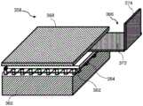
可选地,所述介质计量器包括一个喷丸室或抛丸室(shot blasting chamber),在其内部,喷丸被轰击到工件表面进行精加工。喷丸室可以有各种类型的支架(bracket),以用于放置不同尺寸和形状的工件,上述的介质计量器适用于不同行业的各种工件。上述喷丸室有一个入口,供喷丸向内流动。上述喷丸室有一个出口,在喷丸过程中,对工件进行轰击后的喷丸料被收集起来,并自动转移到所述喷丸室外。因此,所述介质计量器就可以连续工作;从而大大提高了所述介质计量器的生产效率,运行成本也相应地降低。所述喷丸室和支架由硬质材料制成,如碳化钢(carbonized steel),以承受喷丸的反复轰击。更为有利地,所述介质计量器可以包括两个或两个以上的喷丸室,其可以同时进行多个喷丸处理操作,以进一步提高生产率。优选地,所述支架是可移动和/或可旋转的,以便于喷丸处理的操作。此外,在喷丸室中还可以安装监控系统(monitoring system),以用于监控用过喷丸的收集情况。可选地,在所述监控系统内单独地或集成地安装一个警报系统,以用于在喷丸室不能正常工作时发出警报信号,例如入口或出口被喷丸或异物堵塞时。Optionally, the media meter includes a shot blasting chamber or shot blasting chamber within which shot blasting is blasted onto the workpiece surface for finishing. The blast chamber can have various types of brackets for placing workpieces of different sizes and shapes, and the above-mentioned media meter is suitable for various workpieces in different industries. The shot blasting chamber described above has an inlet for the inward flow of shot blasting. The shot peening chamber has an outlet, and during the shot peening process, the shot peening material after bombarding the workpiece is collected and automatically transferred to the shot peening chamber. Therefore, the medium meter can work continuously; thus, the production efficiency of the medium meter is greatly improved, and the operating cost is correspondingly reduced. The shot peening chamber and support are made of hard material, such as carbonized steel, to withstand repeated blasting by shot peening. More advantageously, the media meter may include two or more shot peening chambers, which may perform multiple shot peening operations simultaneously to further increase productivity. Preferably, the holder is movable and/or rotatable to facilitate shot peening operations. In addition, a monitoring system can be installed in the blasting chamber for monitoring the collection of used blasting. Optionally, an alarm system can be installed separately or integrally within the monitoring system to issue an alarm signal when the blast chamber is not functioning properly, such as when the inlet or outlet is blocked by blasting or foreign objects.
可选地,所述介质计量器还包括观察窗,以用于从视觉上检查所述介质计量器。所述观察窗可位于所述循环导管的主支路处,也可位于所述循环导管的侧支路处。对于前者选择,将主之路的一部分移除,然后将观察窗嵌入主之路中。在此,观察窗由透明而耐磨的材料制成,如淬火玻璃(tempered glass)或钢化玻璃(toughened glass)等。可选地,一个屏蔽件(shielding piece)安装在所述观察窗,以保护该观察窗不受周围环境的任何损害或污染。对于后者选择,该观察窗可以用普通透明材料制成,如普通玻璃,因为该观察窗几乎不会被喷丸磨损。在此种情况下,所述观察窗很容易更换,不需要花费太多成本。特别是当所述循环导管是由淬火玻璃(tempered glass)或钢化玻璃(toughened glass)制成时,观察窗就没有必要了。所述观察窗可以位于循环导管的任何位置:例如在入口的水平处、流量传感器的水平处或出口的水平处。优选地,所述观察窗位于流量传感器附近,这样可以通过从视觉上检查和确认从喷丸反射出来的检测信号,以便更准确地控制喷丸流。Optionally, the media gauge further includes a viewing window for visual inspection of the media gauge. The viewing window may be located at the main branch of the circulation conduit, or may be located at the side branch of the circulation conduit. For the former option, part of the main road is removed, and the viewing window is embedded in the main road. Here, the viewing window is made of a transparent and wear-resistant material, such as tempered glass or toughened glass. Optionally, a shielding piece is mounted on the viewing window to protect the viewing window from any damage or contamination of the surrounding environment. For the latter option, the viewing window can be made of ordinary transparent material, such as ordinary glass, since the viewing window is hardly abraded by shot peening. In this case, the viewing window can be easily replaced without too much cost. Especially when the circulation conduit is made of tempered glass or toughened glass, the viewing window is not necessary. The viewing window can be located anywhere in the circulation conduit: for example at the level of the inlet, at the level of the flow sensor or at the level of the outlet. Preferably, the viewing window is located near the flow sensor, so that the detection signal reflected from the shot peening can be visually inspected and confirmed for more accurate control of the shot peening flow.
可选地,所述介质计量器还包括一个用于保存喷丸介质或介质(即喷丸或喷丸颗粒)的喷丸介质储存罐。该储存罐具有一个入口,以用于接收轰击后用过的喷丸;和一个出口,以用于向循环导管提供弹丸。这样,喷丸颗粒可通过在储存罐、循环导管和喷丸室之间循环使用而重新用于所述介质计量器。所述储存罐既可以与循环导管整合在一起,也可以远离循环导管。对于前者,储存罐的出口直接与循环导管的入口相连;喷丸室的出口也直接与储存罐的入口相连。由于其体积小、便于运输、甚至便于人员携带,这种设计的介质计量器适合现场喷丸操作。然而,这种设计的介质计量器有一个缺点,即储存罐的容积非常有限,以至于其只能处理小型工件。对于后者,储存罐的出口和入口分别通过出口管道和入口管道而延伸。这种介质计量器虽然运输不方便,但储存罐的容积可以非常巨大,因此其适用于对非常大的工件进行连续喷丸处理操作,在该过程中无需更换喷丸。Optionally, the media meter further includes a shot peening medium storage tank for holding shot peening medium or media (ie, shot peening or shot peening particles). The storage tank has an inlet for receiving spent blasting post-bombardment shots and an outlet for supplying the pellets to the circulation conduit. In this way, the peening particles can be reused in the media meter by being recycled between the storage tank, the circulation conduit and the peening chamber. The storage tank can either be integrated with the circulation conduit or be remote from the circulation conduit. For the former, the outlet of the storage tank is directly connected to the inlet of the circulation conduit; the outlet of the shot blasting chamber is also directly connected to the inlet of the storage tank. The media meter of this design is suitable for field shot peening operations due to its small size, ease of transport, and even portability. However, the media meter of this design has the disadvantage that the volume of the storage tank is so limited that it can only handle small workpieces. For the latter, the outlet and inlet of the storage tank are extended by outlet and inlet pipes, respectively. Although this media meter is inconvenient to transport, the volume of the storage tank can be very large, so it is suitable for continuous shot peening operations on very large workpieces, without the need to change the shot peening during the process.
可选地,所述介质计量器还包括一个与喷丸循环导管的入口相连接的软管,以用于接收喷丸介质到所述介质计量器中。所述软管的底部位置与喷丸循环导管的入口位置相匹配,使在软管和喷丸循环导管之间不发生泄漏。优选地,所述软管由一种或多种耐磨的柔性材料制成,如橡胶或纤维增强橡胶。所述软管有几个优点:首先,其降低了微波信号对喷丸循环导管的敏感性,从而使微波信号被转移。其次,当喷丸流通过软管时,其还可以作为阻尼物体而减少振动。Optionally, the medium meter further includes a hose connected to the inlet of the shot peening circulation conduit for receiving shot peening medium into the medium meter. The position of the bottom of the hose matches the position of the inlet of the shot peening circulation conduit so that no leakage occurs between the hose and the shot peening circulation conduit. Preferably, the hose is made of one or more abrasion resistant flexible materials, such as rubber or fibre reinforced rubber. The hose has several advantages: First, it reduces the sensitivity of the microwave signal to the peening circulation conduit, thereby allowing the microwave signal to be diverted. Second, it also acts as a damping object to reduce vibration as the blast stream passes through the hose.
可选地,所述介质计量器还包括一个或多个与喷丸循环导管的出口相连接的喷嘴,以用于将喷丸介质释放到喷丸室内的工件上,如金属片。每个喷嘴具有一个宽的顶部部分和一个窄的底部部分。该窄的底部部分对着所述喷丸室内的工件。每个喷嘴均用于聚集通过其的喷丸流,从而使控制喷丸流以可控的尺寸聚焦到工件表面的目标区域。例如,所述喷嘴可以是圆锥形,其尺寸沿着喷丸流的通过路径而逐渐减小。替代地,所述喷嘴可以是漏斗形,在连接宽的顶部部分和窄的底部部分的凹陷部分处尺寸突然改变。也可根据具体要求设计其它类型的喷嘴。在通过喷嘴时,由于喷丸与喷嘴内壁之间的碰撞,以及喷丸之间在气流中的碰撞,喷丸的动量可能会损失。由于喷丸和喷嘴之间几乎没有直接碰撞,动量损失较少,因此圆锥形为优选。在每个喷嘴中,可以预定的速度控制喷丸流,该速度由流量传感器检测进一步控制。此外,在喷丸操作期间,喷嘴可以被移动和/或旋转,从而可以在不移动工件的情况下加工工件的不同区域。Optionally, the media meter further includes one or more nozzles connected to the outlet of the shot peening circulation conduit for releasing the shot peening medium onto the workpiece, such as sheet metal, within the shot peening chamber. Each nozzle has a wide top portion and a narrow bottom portion. The narrow bottom portion faces the workpiece within the blast chamber. Each nozzle is used to focus the flow of shot peening through it so that the controlled shot flow is focused at a controlled size to a target area of the workpiece surface. For example, the nozzles may be conical in shape, gradually decreasing in size along the path of the blast stream. Alternatively, the nozzle may be funnel-shaped, with an abrupt change in size at the recessed portion connecting the wide top portion and the narrow bottom portion. Other types of nozzles can also be designed according to specific requirements. While passing through the nozzle, the momentum of the shot can be lost due to the collision between the shot and the inner wall of the nozzle, as well as the collision between the shot in the airflow. The conical shape is preferred as there is little direct collision between the shot peening and the nozzle and less momentum is lost. In each nozzle, the blast flow can be controlled at a predetermined speed, which is further controlled by flow sensor detection. Additionally, the nozzle can be moved and/or rotated during the shot peening operation, allowing different areas of the workpiece to be machined without moving the workpiece.
可选地,所述介质计量器还包括一个与喷丸介质储存罐连接的喷丸介质加速器。所述介质计量器可以采用空气喷丸机的下述两种系统中的一种,为喷丸颗粒提供动力:加压系统(pressurized system)(即直压式)或真空-吸气系统(vacuum-suction system)(即吸气式)。对于所述加压系统,加速器可以是一个压缩机或使用压缩空气的类似设备,以推动喷丸前进;而对于真空-吸气系统,加速器可以是一个真空吸气杯或产生真空的类似设备,以拉动喷丸前进。也可以安装机械加速器,如叶轮(impeller)或喷丸轮(blast wheel),为随着喷丸流而流动地喷丸粒子提供额外的动力。Optionally, the medium meter further includes a shot peening medium accelerator connected to the shot peening medium storage tank. The media meter can use one of the following two systems of the air blast machine to power the blast particles: a pressurized system (ie direct pressure) or a vacuum-suction system (vacuum) -suction system) (ie suction). For the pressurized system, the accelerator may be a compressor or similar device that uses compressed air to propel the shot peening forward; for the vacuum-suction system, the accelerator may be a vacuum suction cup or similar device that generates a vacuum, To pull the shot peening forward. Mechanical accelerators, such as impellers or blast wheels, can also be installed to provide additional power for the flow of the peened particles with the peening stream.
可选地,介质计量器还包括一个与循环导管相连接的介质流动阀,以用于调节喷丸的流速。一般来说,当阀门部分打开或完全打开时,喷丸可以从储存罐流入循环导管中;而当阀门完全关闭时,喷丸不能流入循环导管中,所述介质计量器停止工作。所述介质流动阀可以是机械阀、电磁阀或其它的类型。机械阀一般有一个机械控制的柱塞(plunger),其默认为可拆卸地位于一个开孔之上。所述开孔与循环导管相连。当流动阀门关闭时,柱塞停留在该开孔上,从储存罐到循环导管的路径被阻断。当操作人员或机械杠杆将柱塞从开孔处抬起时,喷丸流流经孔口的路径通畅并保持开放。电磁阀,例如已知的流量传感器,集成了一个电磁控制柱塞,以用于控制介质流。当电源接通时,电磁铁提升柱塞,使喷丸流过通过开孔。当电源被关闭或因任何原因而中断时,柱塞会回到其静止位置,从而阻挡喷丸流。柱塞的设计是为了安全地保持喷丸流,因此实际上消除了任何介质的泄漏。所述电磁阀有一个很大的优点,就是可以用可编程控制器(programmable controller),如FC-24控制器与已知的流量传感器而集成为一个自动闭环系统。与机械阀相比,电磁阀的可编程控制器对喷丸流的调节更加精确。对于所述介质计量器,在可编程控制器和电磁阀的帮助下,可以精确地重复所需的流量。此外,可编程控制器可以通过预先设定的程序自动控制,无需操作人员参与,生产效率显著提高。Optionally, the medium meter further includes a medium flow valve connected with the circulation conduit for adjusting the flow rate of the shot blasting. Generally, when the valve is partially open or fully open, shot peening can flow from the storage tank into the circulation conduit; and when the valve is fully closed, shot peening cannot flow into the circulation conduit, and the media meter stops working. The medium flow valve may be a mechanical valve, a solenoid valve or other types. Mechanical valves typically have a mechanically controlled plunger, which by default is removably positioned over an opening. The opening is connected to the circulation conduit. When the flow valve is closed, the plunger rests on the opening and the path from the storage tank to the circulation conduit is blocked. When an operator or a mechanical lever lifts the plunger from the orifice, the shot flow path through the orifice is unobstructed and remains open. Solenoid valves, such as known flow sensors, integrate a solenoid-operated plunger for controlling the flow of the medium. When the power is turned on, the electromagnet lifts the plunger, allowing the shot blast to flow through the opening. When the power is turned off or interrupted for any reason, the plunger returns to its rest position, blocking the blast flow. The plunger is designed to safely maintain the blast flow, thus virtually eliminating any leakage of media. The solenoid valve has the great advantage that it can be integrated into an automatic closed loop system using a programmable controller, such as the FC-24 controller, and a known flow sensor. Compared to mechanical valves, the programmable controller of the solenoid valve regulates the shot flow more precisely. For the media meter, with the help of programmable controllers and solenoid valves, the desired flow rate can be precisely repeated. In addition, the programmable controller can be automatically controlled by pre-set programs without operator involvement, and the production efficiency is significantly improved.
所述流动阀既可以作为上游而安装在流量传感器之前游,也可以作为下游而安装在流量传感器之后,或者与流量传感器安装在一起。一般情况下,流动阀最好与流量传感器合为一体,以节省内部空间,同时也使所述介质计量器的结构不那么复杂,便于维护和维修。例如,在700-24上集成了一个作为流量传感器的桨叶。喷丸介质通过柱塞并落到桨叶上,根据介质的流速使桨叶弯曲,从而产生准确的流速信号。优选地,流动阀与流量传感器进行电领域通信(electrical communication)。因此,流动阀的控制器可以根据流量传感器检测的流量的实时测量结果而进行工作。在电气通信没有延迟的情况下,流动阀的控制器和流量传感器之间建立了一个闭合的反馈控制回路(closed feedback control loop)。The flow valve can either be installed upstream of the flow sensor, or downstream of the flow sensor, or together with the flow sensor. In general, the flow valve is preferably integrated with the flow sensor to save internal space, and at the same time, the structure of the medium meter is less complicated, which is convenient for maintenance and repair. For example, a paddle that acts as a flow sensor is integrated on the 700-24. The shot peening medium passes through the plunger and falls onto the paddle, which bends according to the flow rate of the medium, resulting in an accurate flow rate signal. Preferably, the flow valve is in electrical communication with the flow sensor. Therefore, the controller of the flow valve can operate according to the real-time measurement of the flow rate detected by the flow sensor. With no delay in electrical communication, a closed feedback control loop is established between the controller of the flow valve and the flow sensor.
所述介质流动阀可以被配置为在没有电力供应的情况下,在默认位置打开或优选地关闭喷丸循环导管的流动通道。例如,如果介质流动阀在默认位置关闭,则介质计量器在没有电力供应的情况下不进行工作。一旦打开电气开关,喷丸介质首先从储存罐供给到循环导管中,然后沿着循环导管流向工件;最后被收集并再循环回储存罐中。相反地,在没有电的情况下,如果介质流动阀在默认位置打开,则介质计量器的工作方式即相反。The medium flow valve may be configured to open or preferably close the flow channel of the shot peening circulation conduit in a default position in the absence of power supply. For example, if the medium flow valve is closed in the default position, the medium meter will not operate without power supply. Once the electrical switch is turned on, the blasting medium is first fed from the storage tank into the circulation conduit, and then flows along the circulation conduit to the workpiece; finally, it is collected and recycled back into the storage tank. Conversely, in the absence of electricity, if the media flow valve is open in the default position, the media meter works in reverse.
实时运行状态可用图表表示,以喷丸流量为X轴,以流量传感器检测到的信号为Y轴。喷丸流量以公斤/分钟为单位。所述图形必须呈线性上升趋势,即Y轴的流量传感器信号随X轴的喷丸流量地增加而线性增加。如果使用微波传感器作为流量传感器,对于非铁质喷丸,由于微波传感器发射的微波很容易穿过非铁质材料,因此仅少量微波从非铁质喷丸反射回微波传感器,所以很容易得到所述介质计量器的线性图。相反地,微波不容易穿透铁质材料,因此通常大量微波从铁质喷丸反射到微波传感器中。The real-time operating status can be represented by a graph, with the shot peening flow as the X-axis and the signal detected by the flow sensor as the Y-axis. The shot peening flow is in kg/min. The graph must have a linear upward trend, ie the flow sensor signal on the Y-axis increases linearly with the peening flow on the X-axis. If a microwave sensor is used as a flow sensor, for non-ferrous shot peening, since the microwave emitted by the microwave sensor can easily pass through the non-ferrous material, only a small amount of microwave is reflected from the non-ferrous shot back to the microwave sensor, so it is easy to obtain all the Linear diagram of the media meter described above. Conversely, microwaves do not easily penetrate ferrous materials, so typically a large amount of microwaves is reflected from the ferrous shot into the microwave sensor.
所述微波流量传感器对铁质喷丸介质有两大问题。首先,由于微波不能穿透金属材料,所以只能检测到位于铁质介质流外围的铁质喷丸颗粒的反射信号。而在微波无法到达的铁质介质流的内侧部分,铁质喷丸颗粒几乎可被忽略。其次,由于微波对铁质材料的微波反射具有极低的衰减效应,即使铁质喷丸介质流速较慢,微波传感器也很容易达到饱和状态。所述介质喷丸装置经过一些新功能的改造,解决了铁质喷丸颗粒的问题。The microwave flow sensor has two major problems with iron shot peening media. First, since microwaves cannot penetrate metallic materials, only the reflected signal of ferrous shot particles located at the periphery of the ferrous medium flow can be detected. In the inner part of the ferrous medium flow, which cannot be reached by microwaves, the ferrous shot particles are almost negligible. Second, because microwaves have extremely low attenuation effects on the microwave reflection of ferrous materials, the microwave sensor can easily reach saturation even if the flow rate of the ferrous shot peening medium is slow. The media shot peening device has been transformed with some new functions to solve the problem of iron shot peening particles.
为了满足所述介质计量器的流量传感器的要求,其还可以包括一个介质导流器(media guider)(即导流器或介质导流器)或介质流量分配器(media flow distributor),以用于改变或调整喷丸的流动模式。喷丸在循环导管中基本上以两种不同的模式流动:聚集模式或分散模式。对于聚集模式,喷丸颗粒被组合成一个或多个簇(cluster),每个簇有一个位于簇外围的外部部分和一个包封在所述外部部分之内的内部部分。因此,内部部分的喷丸很难通过流量传感器被检测到。对于分散模式,喷丸粒子彼此分离,不直接接触,因此几乎所有的喷丸粒子都可以用流量传感器检测到。所述介质计量器的导流器可以将喷丸流从聚集模式改变为分散模式。此外,所述导流器还可以稍加调整散射图案。例如,当喷丸流的散射图案中的两个相邻喷丸之间的距离很短时;导流器可将该短距离调整为较大距离。换句话说,分散模式的喷丸流在通过一种类型的导流器后变得更加分散。与此相反,较分散的喷丸流模式可以通过另一种导流器调整为较不分散的模式。但是,喷丸流仍然保持为分散模式。导流器是根据所述流量传感器和介质计量器所使用的喷丸材料的性质来选择的。例如,当采用微波传感器时,为了给铁质喷丸流提供散射图案,所述导流器是必要的。而对于非铁质喷丸流,由于非铁质喷丸流的聚集图案或散射图案都适用于微波流传感器,所以导流器不是必须的。In order to meet the requirements of the flow sensor of the media meter, it may also include a media guider (ie, a flow guide or a media guide) or a media flow distributor to use To change or adjust the flow pattern of the shot peening. The shot peening basically flows in two different modes in the circulation duct: agglomerated mode or dispersed mode. For the aggregated mode, the peening particles are combined into one or more clusters, each cluster having an outer portion located at the periphery of the cluster and an inner portion enclosed within the outer portion. Therefore, the shot peening of the inner part is difficult to be detected by the flow sensor. For dispersion mode, the shot particles are separated from each other and not in direct contact, so almost all shot particles can be detected with the flow sensor. The flow director of the media meter can change the shot peening flow from an agglomerated mode to a dispersive mode. In addition, the deflector can also slightly adjust the scattering pattern. For example, when the distance between two adjacent shots in the scattering pattern of the shot stream is short; the deflector can adjust the short distance to a larger distance. In other words, the peening stream in dispersed mode becomes more dispersed after passing through one type of deflector. In contrast, a more dispersed shot flow pattern can be adjusted to a less dispersed pattern by another flow director. However, the shot peening flow remains in dispersed mode. The flow director is selected based on the properties of the shot peening material used for the flow sensor and media meter. For example, when using a microwave sensor, the deflector is necessary in order to provide a scattering pattern to the ferrous shot stream. And for non-ferrous shot peening flow, the flow deflector is not necessary since both the gathering pattern or the scattering pattern of the non-ferrous shot peening flow are suitable for the microwave flow sensor.
优选地,所述导流器或介质导流器包括一个或多个第一分散器(spreader),以用于使喷丸介质流分散或变形。第一分散器具有多个开口(opening)或穿孔(perforation),以供喷丸通过。所述多个开口中的每个开口都包括一个用于限定该开口的框架(frame)和一个或多个供喷丸粒子通过的孔(hole)。因此,喷丸颗粒被框架扩散或分散,从而使喷丸颗粒流发生变形。同时,由于喷丸粒子与第一分散器的框架之间发生碰撞,喷丸粒子的流动被第一扩散器所减缓。因此,其可以有效降低反射微波的信号强度。所述开口的孔的形状、大小和位置可以根据具体的要求而变化。例如,孔的形状可以是方形、圆形,甚至是不规则的。所述孔在最窄处测量的尺寸大于喷丸粒子的直径。例如,矩形孔的长度为3~60毫米,宽度为3~10毫米;而圆形孔的直径为3~40毫米。每个孔在开口的框架内的位置也可以灵活设计。特别地,如果采用混合喷丸的话,开口处可以有不同类型的孔,以用于对不同喷丸粒子进行分类。Preferably, the deflector or media deflector comprises one or more first spreaders for dispersing or deforming the flow of shot peening media. The first disperser has a plurality of openings or perforations for the passage of shot blasting. Each of the plurality of openings includes a frame for defining the opening and one or more holes for the passage of shot peening particles. As a result, the shot particles are diffused or dispersed by the frame, thereby deforming the flow of shot particles. At the same time, the flow of the shot peened particles is slowed down by the first diffuser due to collisions between the shot peened particles and the frame of the first disperser. Therefore, it can effectively reduce the signal strength of reflected microwaves. The shape, size and location of the apertures of the openings may vary according to specific requirements. For example, the shape of the holes can be square, round, or even irregular. The size of the hole, measured at its narrowest point, is greater than the diameter of the peening particle. For example, a rectangular hole has a length of 3 to 60 mm and a width of 3 to 10 mm; while a circular hole has a diameter of 3 to 40 mm. The position of each hole within the frame of the opening can also be flexibly designed. In particular, if hybrid peening is used, the openings may have different types of holes for sorting the different peening particles.
可选地,所述第一分散器由一个或多个子单元组成,其包括筛网(sieve)、网眼(meshe)、穿孔板(perforated plate)、缝隙(slit)、穿刺块(punctured block)、通槽(through channel)、通轴(through spindle)、分配板(distributing plate)、加压气枪(pressurised air gun)、静态或动态电磁场(static or dynamic electromagneticfield)、振动器(vibrator)或料斗(hopper)或类似物。如果所述第一分散器的两个或两个以上的子单元安装在导流器中,该子单元可以线性、垂直或以任何角度来排列。例如,两个钢丝网相互堆叠,其纵向轴线相向排列,使通过底部第二钢丝网的喷丸介质与只通过顶部第一钢丝网的喷丸介质相比,变得更加均匀分布。第一分散器的子单元设计灵活。例如,第一分散器的两个或多个子单元可以与循环导管对齐,也可以相互对齐,或者与循环导管及相互都对齐。Optionally, the first disperser is composed of one or more sub-units including a sieve, a mesh, a perforated plate, a slit, a punctured block, through channel, through spindle, distributing plate, pressurised air gun, static or dynamic electromagnetic field, vibrator or hopper ) or the like. If two or more sub-units of the first disperser are installed in the deflector, the sub-units can be arranged linearly, vertically or at any angle. For example, two wire meshes are stacked on top of each other, with their longitudinal axes facing toward each other, resulting in a more even distribution of blasting media through the second wire mesh at the bottom than if the media passed through the first mesh at the top only. The subunits of the first diffuser are flexible in design. For example, the two or more subunits of the first disperser can be aligned with the circulation conduit, with each other, or with both the circulation conduit and each other.
所述第一分散器或其子单元可由适合特定要求的各种材料制成。例如,对于铁质喷丸,第一分散器优选地由硬质材料制成,如钢筋(reinforced steel),其对碰撞的承受能力更强;而对于非铁质喷丸,第一分散器可以由其它金属制成,如铜或铝合金,其抗化学侵蚀能力更强。The first disperser or its subunits may be made of various materials suitable for specific requirements. For example, for ferrous shot peening, the first disperser is preferably made of a hard material, such as reinforced steel, which is more resistant to impact; while for non-ferrous shot peening, the first disperser may be Made of other metals, such as copper or aluminum alloys, which are more resistant to chemical attack.
所述导流器可以永久地或可拆卸地安装在所述介质计量器的流量传感器中。例如,导流器可以永久地焊接在流量传感器上。但是,当导流器损坏时,必须更换整个流量传感器。替代地,导流器可以安装有夹子,当夹子松开时,导流器可以从流量传感器上分离。替代地,导流器可以用螺母拧紧(screwed),用杆子钉住(pinned),或者用绳子绑在流量传感器上。因此,损坏或磨损的导流器就可以更换为新的导流器。与固定安装的导流器相比,更换可拆式导流器的成本更低,更换操作也更简单。可拆式导流器还有一个优点,即一种类型的可拆式导流器可以被另一种类型的可拆式导流器所取代,而无需改变整个流量传感器。总之,每个分散器可以永久或可拆卸地安装在导流器中;而每个子单元也可以永久或可拆卸地安装在第一分散器中。此外,除了流量传感器之外,所述导流器可以沿着循环导管的任何位置永久地或可拆卸地安装。还可以使用一个或多个额外的导流器,以更显著地改变或调整喷丸流的模式。综上所述,所述导流器的设计具有最大的灵活性,能满足多样化的要求,成本低,更换操作方便。The deflector may be permanently or removably mounted in the flow sensor of the media meter. For example, the deflector can be permanently welded to the flow sensor. However, when the deflector is damaged, the entire flow sensor must be replaced. Alternatively, the flow deflector can be fitted with a clip that can be detached from the flow sensor when the clip is released. Alternatively, the deflector may be screwed, pinned, or tied to the flow sensor with a string. Thus, a damaged or worn deflector can be replaced with a new deflector. Removable deflectors are less expensive to replace and simpler to replace than fixed-mounted deflectors. Detachable deflectors also have the advantage that one type of demountable deflector can be replaced by another type of demountable deflector without changing the entire flow sensor. In summary, each diffuser can be permanently or removably installed in the deflector; and each subunit can also be permanently or removably installed in the first diffuser. Furthermore, the flow director may be permanently or removably installed anywhere along the circulation conduit, except for the flow sensor. One or more additional flow directors may also be used to more significantly alter or adjust the pattern of the shot peening flow. To sum up, the design of the deflector has maximum flexibility, can meet diverse requirements, is low in cost, and is easy to replace and operate.
可选地,所述流量传感器还包括信号调节器,以用于调节流量传感器的信号强度,引导微波(例如改变角度)或聚焦微波。为了便于控制喷丸介质流,信号强度落在图上的线性区域内,通过该区域监测实时的操作状态。当喷丸颗粒的反射信号过强时,流量传感器趋于饱和,从而使运行状态落在图上的线性区域之外。对于特定喷丸介质和特定流量传感器的组合,饱和问题会非常严重,即使喷丸介质的流量仍然低于要求,但所述介质计量器不能正常工作。Optionally, the flow sensor further includes a signal conditioner for adjusting the signal strength of the flow sensor, directing the microwaves (eg, changing the angle) or focusing the microwaves. To facilitate control of the peening media flow, the signal intensity falls within a linear region on the graph through which real-time operating conditions are monitored. When the reflected signal from the peening particles is too strong, the flow sensor tends to saturate, causing the operating conditions to fall outside the linear region on the graph. For certain combinations of peening media and certain flow sensors, the saturation problem can be so severe that even though the flow of the peening media is still lower than required, the media meter does not work properly.
例如,当所述介质计量器中采用铁质喷丸介质和微波流量传感器时,信号调节器可选地包括微波信号调节器(也称为微波信号衰减器)。铁质喷丸反射的信号太强,微波流量传感器容易饱和,从而低于要求的流量。为了克服这个问题,采用微波信号调节器,以用于吸收和(或)将一部分反射的微波信号转到微波流量传感器之外。反射信号的剩余部分将被微波传感器检测到。因此信号强度降低,运行状态又落回图形的线性区域。优选地,所述微波信号调节器是吸收型,因为信号的吸收部分不会干扰反射信号的剩余部分。相反地,信号的再定向(redirected)部分对剩余部分的信号可能是噪声。微波信号调节器可以由填充有磁性颗粒的高分子材料(称为磁性吸收器)、浸渍有碳涂层的开孔泡沫(称为泡沫吸收器)或其它具有类似性质的材料制成。磁性吸收剂同时具有高磁导率(permeability)(即磁损失特性(magnetic loss properties))和高介电率(permittivity)(即介电损失特性(dielectric loss properties))。这两种特性的结合,使得磁吸收体非常适用于高频的微波信号。泡沫吸收器的作用就像一个自由空间的阻抗(free space resistor)一样,可以抵抗传入的电磁能量,因此适用于几乎全频谱的微波信号。For example, when ferrous shot peening media and microwave flow sensors are employed in the media meter, the signal conditioner optionally includes a microwave signal conditioner (also referred to as a microwave signal attenuator). The signal reflected by the iron peening is too strong, and the microwave flow sensor tends to saturate, thus lowering the required flow rate. To overcome this problem, microwave signal conditioners are employed to absorb and/or divert a portion of the reflected microwave signal out of the microwave flow sensor. The remainder of the reflected signal will be detected by the microwave sensor. As a result, the signal strength decreases and the operating state falls back into the linear region of the graph. Preferably, the microwave signal conditioner is of the absorbing type, as the absorbing portion of the signal does not interfere with the remainder of the reflected signal. Conversely, the redirected portion of the signal may be noise to the remaining portion of the signal. Microwave signal conditioners can be made of polymeric materials filled with magnetic particles (called magnetic absorbers), open-cell foams impregnated with a carbon coating (called foam absorbers), or other materials with similar properties. Magnetic absorbers have both high permeability (ie, magnetic loss properties) and high permittivity (ie, dielectric loss properties). The combination of these two properties makes the magnetic absorber very suitable for high frequency microwave signals. The foam absorber acts like a free space resistor against incoming electromagnetic energy and is therefore suitable for almost the full spectrum of microwave signals.
可选地,所述信号调节器包括一个或多个由信号衰减材料(例如吸收或再定向材料)制成的分层;或信号增强材料。因此,信号调节器可根据流速和喷丸颗粒的性质,其减弱或增强反射信号的功能是可调节的。对于铁质喷丸颗粒,当流速过快时,可附加一层信号吸收或再定向材料,以进一步降低信号强度;而流速较慢时,可将一些分层从信号调节器上脱离,以增强信号强度。对于流速较慢的非铁质喷丸,由于反射信号强度很容易落在图形的线性区域内,所以不需要所述信号调节器;而流速过低时,可以附加一些增强层,以增强信号强度从而进入图形的线性区域。Optionally, the signal conditioner includes one or more layers of signal attenuating material (eg, absorbing or redirecting material); or signal enhancing material. Therefore, the signal conditioner can be adjusted according to the flow rate and the properties of the peening particles, its function of weakening or enhancing the reflected signal is adjustable. For iron peening particles, when the flow rate is too fast, an additional layer of signal absorbing or redirecting material can be added to further reduce the signal strength; at slower flow rates, some layers can be detached from the signal conditioner to enhance signal strength. For non-ferrous shot peening with slow flow rate, the signal conditioner is not needed because the reflected signal intensity easily falls within the linear region of the graph; while the flow rate is too low, some enhancement layers can be added to enhance the signal strength Thus entering the linear region of the graph.
为了改变影响或调节的效果,所述信号调节器可从流量传感器拆下。例如,当所述介质计量器需要高频微波信号时,首先将现有的带泡沫吸收器的信号调节器从流量传感器拆下,然后将另一个带磁性吸收器的信号调节器连接到流量传感器上。此外,如果现有的信号调节器损坏,可以通过简单的操作更换为新的信号调节器。必要时,一种类型的信号调节器可以被另一种不同类型的信号调节器所取代。例如,当流量传感器需要使用光学信号调节器时,可将现有的微波信号调节器从流量传感器拆下,然后连接光学信号调节器。In order to change the effect of the influence or adjustment, the signal conditioner can be detached from the flow sensor. For example, when the media meter requires a high frequency microwave signal, first remove the existing signal conditioner with foam absorber from the flow sensor, and then connect another signal conditioner with magnetic absorber to the flow sensor superior. In addition, if the existing signal conditioner is damaged, it can be replaced with a new signal conditioner with a simple operation. When necessary, one type of signal conditioner can be replaced by a different type of signal conditioner. For example, when an optical signal conditioner is required for the flow sensor, the existing microwave signal conditioner can be detached from the flow sensor and then connected to the optical signal conditioner.
可选地,所述信号调节器还包括连接到喷丸循环导管的一个或多个部分(例如作为壁)的套筒,以便在反射信号太强时吸收或再定向一部分反射信号;或在反射信号太弱时增强反射信号。类似地,所述套筒可以包括一层或多层信号衰减材料,例如吸收或再定向材料;或信号增强材料。因此,所述套筒能够根据流速和喷丸颗粒的性质,在减弱或增强反射信号方面进行调整。对于铁质喷丸,当流速过快时,可加入额外的信号吸收或再定向材料层,以降低更多的信号强度;而流速过慢时,可将一些所述分层从循环导管分离出来。对于流速较慢的非铁质喷丸,由于反射信号强度很容易落在图形的线性区域内,所以不需要套筒;而流速过低时,可以附加一些增强层,以增加进入图形线性区域的信号强度。Optionally, the signal conditioner further comprises a sleeve connected to one or more portions of the shot peening circulation conduit (eg as a wall) to absorb or redirect a portion of the reflected signal if the reflected signal is too strong; or if the reflected signal is too strong; Boosts the reflected signal when the signal is too weak. Similarly, the sleeve may include one or more layers of signal attenuating material, such as absorbing or redirecting material; or signal enhancing material. Thus, the sleeve can be adjusted to reduce or enhance the reflected signal depending on the flow rate and the properties of the peening particles. For iron peening, when the flow rate is too fast, additional layers of signal absorbing or redirecting material can be added to reduce more signal intensity; when the flow rate is too slow, some of these layers can be separated from the circulation conduit . For non-ferrous shot peening with a slow flow rate, since the intensity of the reflected signal easily falls within the linear region of the pattern, a sleeve is not required; when the flow rate is too low, some enhancement layers can be added to increase the penetration rate into the linear region of the pattern. signal strength.
优选地,所述介质计量器还包括与介质流动阀、流量传感器或两者都连接的料斗,以用于给喷丸颗粒(即喷丸)进料。料斗具有宽大的顶部开口、向下的渐缩体(taperingbody)和狭窄的底部开口。所述储存罐中的喷丸颗粒从顶部开口进入料斗,经过本体,最后从底部开口排出料斗。根据预定的方式,料斗中的喷丸颗粒可以平稳地、连续地或以任何预定的方式排出。料斗的主要优点是,由于顶部开口较宽,可以很容易地将喷丸颗粒送入所述介质计量器中。此外,当喷丸颗粒流过料斗时,由于其与料斗的内壁之间可能发生碰撞,因此喷丸颗粒可能会相互散开。因此,料斗提供了一个额外改变或调整丸流模式的过程。Preferably, the media meter further comprises a hopper connected to a media flow valve, a flow sensor, or both, for feeding shot peening particles (ie, shot blasting). The hopper has a wide top opening, a downward tapering body and a narrow bottom opening. The shot peening particles in the storage tank enter the hopper from the top opening, pass through the body, and finally discharge the hopper from the bottom opening. Depending on the predetermined manner, the blasted particles in the hopper can be discharged smoothly, continuously or in any predetermined manner. The main advantage of the hopper is that due to the wide top opening, the blasting particles can be easily fed into the media meter. In addition, as the shot particles flow through the hopper, the shot particles may disperse from each other due to possible collisions with the inner wall of the hopper. Therefore, the hopper provides an additional process for changing or adjusting the shot flow pattern.
可选地,所述介质计量器还可包括保护壳,以用于将流量传感器、介质流动阀、循环导管、料斗或任何其它部件封闭起来,形成一个整体。保护壳为所有内部组件提供了一个保护性外壳,使其免受外界的污染甚至可能的危害。所述保护壳的等级是根据IP等级标准(IP Marking standard)(国际防护等级(International Protection Marking)或异物防护等级(Ingress Protection Marking)),该标准对防止入侵、灰尘、意外接触和水的保护程度进行分类。优选地,所述储存罐的入口与循环导管的入口之间的接口按IP68标准保护。IP68标准被认为足以抵御灰尘、污垢和沙子的侵袭,并且还可以抵御在水下最大1.5米深度的浸泡,时间长达30分钟。否则,水甚至湿气会严重损害所述介质计量器,因为几乎所有的金属部件,包括铁质喷丸和金属工件都缺乏足够的抗化学侵蚀能力。Optionally, the medium meter may further include a protective casing for enclosing the flow sensor, medium flow valve, circulation conduit, hopper or any other components to form a whole. The protective case provides a protective enclosure for all internal components from outside contamination and even possible hazards. The protective case is rated according to the IP Marking standard (International Protection Marking or Ingress Protection Marking) for protection against intrusion, dust, accidental contact and water degree of classification. Preferably, the interface between the inlet of the storage tank and the inlet of the circulation conduit is protected according to the IP68 standard. The IP68 standard is considered adequate against dust, dirt and sand, and can also withstand immersion underwater up to a depth of 1.5 meters for up to 30 minutes. Otherwise, water or even moisture can seriously damage the media meter, since almost all metal parts, including iron shot peening and metal workpieces, lack sufficient chemical resistance.
可选地,所述介质计量器的介质流动阀还可以包括支托(holder),该支托具有通孔,以用于与喷丸循环导管对准,便于通过通孔传输喷丸颗粒;以及由支托支撑并与支托排列的活动窗(shutter)。该支托还包括具有第一通孔的基板(base plate),以及置于底板上的具有第二通孔的底板(bottom plate)。特别地,通孔包括基板的第一通孔和底板的第二通孔。所述活动窗还包括阀控滑轮(valve pulley)和安装在阀控滑轮上的顶板(topplate)。在支托中,底板为介质流动阀整体提供机械支撑;而底板为包括阀控滑轮和顶板的活动窗提供支撑。顶板可以部分或完全覆盖通孔,包括第一通孔和第二通孔。Optionally, the media flow valve of the media meter may further include a holder having a through hole for alignment with the shot peening circulation conduit to facilitate the transfer of shot peening particles through the through hole; and A shutter supported by and aligned with the standoffs. The support further includes a base plate with a first through hole, and a bottom plate with a second through hole placed on the base plate. In particular, the through holes include a first through hole of the base plate and a second through hole of the base plate. The movable window also includes a valve pulley and a topplate mounted on the valve pulley. In the support, the bottom plate provides mechanical support for the medium flow valve as a whole; and the bottom plate provides support for the movable window including the valve control pulley and the top plate. The top plate may partially or completely cover the through holes, including the first through holes and the second through holes.
在一些实施例中,所述活动窗相对于支托是可移动的,以用于调整通孔的开口大小,进而调节喷丸颗粒的流速。当完全覆盖时,介质流动阀完全关闭;由于介质流不能通过顶板和介质流动阀,所述介质计量器将停止工作。当部分覆盖或不覆盖时,介质流动阀打开;所述介质计量器将开始工作。因此,可以通过控制顶板对通孔的覆盖率来调节介质的流量。覆盖率越小,介质的流量越大。上述所有部件都是由对介质喷丸颗粒耐磨的材料制成。特别地,顶板由能够抵抗介质喷丸颗粒反复碰撞的材料制成。In some embodiments, the movable window is movable relative to the support, so as to adjust the size of the opening of the through hole, thereby adjusting the flow rate of the shot peening particles. When fully covered, the media flow valve is fully closed; since the media flow cannot pass through the top plate and the media flow valve, the media meter will stop working. When partially covered or uncovered, the media flow valve opens; the media meter will start working. Therefore, the flow rate of the medium can be adjusted by controlling the coverage ratio of the top plate to the through hole. The smaller the coverage, the greater the flow of the medium. All of the above components are made of materials that are wear-resistant to medium shot peening particles. In particular, the top plate is made of a material that is resistant to repeated collisions of medium shot particles.
可选地,所述基板的第一通孔从基板的底面延伸至基板的顶面。第一通孔可以位于基板的任意位置。优选地,第一通孔位于基板的中心位置。第一通孔的形状可以为任意形状,如矩形或圆形。所述底板的第二通孔从其底面延伸至其顶面。第二通孔可以位于底板的任何位置。优选地,第二通孔位于底板的中心位置。第二通孔可以是任何形状,例如长方形,长度范围为25至32毫米,宽度范围为25至60毫米。替代地,第二通孔为圆形,直径范围为25至60毫米。第一通孔和第二通孔至少部分重叠,以形成喷丸颗粒(即喷丸)的路径。更有利的是,第一通孔和第二通孔具有相同的尺寸和形状。更有利的是,当底板放在基板上时,第一通孔和第二通孔完全重合。Optionally, the first through hole of the substrate extends from the bottom surface of the substrate to the top surface of the substrate. The first through hole may be located anywhere on the substrate. Preferably, the first through hole is located at the center of the substrate. The shape of the first through hole can be any shape, such as a rectangle or a circle. The second through hole of the bottom plate extends from its bottom surface to its top surface. The second through hole can be located anywhere on the bottom plate. Preferably, the second through hole is located in the center of the bottom plate. The second through hole can be of any shape, such as a rectangle, with a length ranging from 25 to 32 mm and a width ranging from 25 to 60 mm. Alternatively, the second through hole is circular with a diameter ranging from 25 to 60 mm. The first through hole and the second through hole at least partially overlap to form a path for shot peening particles (ie, shot blasting). More advantageously, the first through hole and the second through hole have the same size and shape. More advantageously, when the base plate is placed on the substrate, the first through hole and the second through hole are completely coincident.
可选地,所述活动窗包括顶板和连接在顶板上的用于使顶板相对于支托相移动的阀控滑轮(valve pulley)。介质流动阀中的活动窗的顶板可通过阀控滑轮相对于包括基板和底板的支托移动。阀控滑轮可以通过手动控制,也可以通过开关自动控制。该开关还可以与逻辑门或可编程逻辑器件(Programmable Logic Device(PLD))连接。逻辑门具有固定的功能,如AND、OR、XOR、NOT、NAND、NOR、XNOR或这些功能的任意组合。相反地,可编程逻辑器件包括可编程逻辑阵列(Programmable Logic Array(PLA))、可编程阵列逻辑(ProgrammableArray Logic(PAL))、通用阵列逻辑(Generic Array Logic(GAL))、复杂可编程逻辑器件(Complex Programmable Logic Device(CPLD))、场效应可编程门阵列(Field-Programmable Gate Array(FPGA))或其它类型。当必须改变或调整介质流动阀的工作程序时,最好采用可编程逻辑器件。例如,当所述介质计量器与电源断开时,将顶板设置在故障位置,使两个通孔完全被覆盖。在给介质计量器供电后,打开开关,使顶板按照可编程逻辑器件的程序由阀控滑轮拉出;从而使两个通孔部分或全部打开,使介质喷丸流通过介质计量器。介质喷丸流的流量可以通过阀控滑轮调整顶板的位置来控制。该调整可以被编程并存储在可编程逻辑器件中,以便自动控制介质流动阀和进一步控制对介质计量器的操作。Optionally, the movable window includes a top plate and a valve pulley connected to the top plate for moving the top plate relative to the support. The top plate of the movable window in the medium flow valve can be moved relative to the support including the base plate and the bottom plate by the valve control pulley. The valve-controlled pulley can be controlled manually or automatically by a switch. The switch can also be connected to a logic gate or a Programmable Logic Device (PLD). Logic gates have fixed functions such as AND, OR, XOR, NOT, NAND, NOR, XNOR or any combination of these functions. Conversely, programmable logic devices include Programmable Logic Array (PLA), Programmable Array Logic (PAL), Generic Array Logic (GAL), Complex Programmable Logic Devices (Complex Programmable Logic Device (CPLD)), Field-Programmable Gate Array (FPGA), or other types. When the working program of the medium flow valve must be changed or adjusted, it is best to use a programmable logic device. For example, when the media gauge is disconnected from the power source, the top plate is set in the fault position so that the two through holes are completely covered. After power is supplied to the medium meter, the switch is turned on, so that the top plate is pulled out by the valve-controlled pulley according to the program of the programmable logic device; thus, the two through holes are partially or fully opened, and the medium shot peening flows through the medium meter. The flow rate of the medium shot peening flow can be controlled by adjusting the position of the top plate through the valve control pulley. This adjustment can be programmed and stored in the programmable logic device to automatically control the media flow valve and further control the operation of the media meter.
可选地,所述活动窗或介质计量器包括一个顶板,以用于提供非水平的表面(即不是水平地表面或倾斜地表面),特别是在喷丸使用时或安装在喷丸机中时,以用于防止喷丸颗粒在重力作用下在活动窗或顶板处堆积或堵塞。间隙(gap)可能形成于顶板、阀控滑轮和底板之间。当介质喷丸流通过介质流动阀时,一些喷丸流颗粒可能会被夹住并储存在该间隙内。如果残余颗粒不时地从间隙中掉出并与喷丸流重新融合,就有可能干扰介质喷丸的流动。所述干扰会使介质喷丸的流动不稳定,从而导致监测和控制困难。当喷丸颗粒较细或流量较大时,该问题更为严重。为了克服这个问题,将底板、阀控滑轮和顶板倾斜在基板上,使喷丸滚回底板的第二个通孔。倾斜角度最好是在20°至80°的程度范围内。这样,即使粒径很细和/或流量很大,介质流动阀也不会被喷丸流卡住。此外,在操作过程中,介质喷丸流动阀中没有残留颗粒,介质喷丸流动阀的流量可以相对时间更稳定。Optionally, the movable window or media meter includes a top plate for providing a non-horizontal surface (i.e. not a horizontal or sloping surface), especially when shot peening is used or installed in a shot peening machine When used to prevent shot peening particles from accumulating or clogging at the movable window or roof under the action of gravity. A gap may be formed between the top plate, the valve pulley and the bottom plate. As the media shot stream passes through the media flow valve, some of the shot stream particles may become trapped and stored in the gap. From time to time, residual particles fall out of the gap and re-integrate with the peening stream, potentially disrupting the flow of media peening. Such disturbances can make the flow of the media peening unstable, making monitoring and control difficult. The problem is exacerbated when the peening particles are finer or the flow rate is larger. To overcome this, tilt the bottom plate, valve pulley and top plate over the base plate so that the shot peening rolls back to the second through hole of the base plate. The angle of inclination is preferably in the range of 20° to 80°. This way, even with very fine particle sizes and/or high flow rates, the media flow valve will not get stuck with the blast stream. In addition, during operation, there are no residual particles in the media shot peening flow valve, and the flow rate of the media shot peening flow valve can be more stable with respect to time.
可选地,所述介质流动阀的支托还包括具有至少一个预定尺寸(例如直径)的开口(opening)、孔(hole)或穿孔(perforation)的分散器。该分散器也被称为第二分散器,例如网状物(mesh)或穿孔板(perforated plate)。可选地,第二分散器放置在基板和底板之间,以用于散开喷丸颗粒(即喷丸),从而使进入的喷丸流产生变形。第二分散器在结构、材料等方面与第一分散器相似。所述第二分散器可以永久地或可拆卸地安装在介质流动阀中。优选地,支托的分散器(即第二扩张器)可从介质流动阀中拆卸、分离或更换,使得第二分散器在需要时可拆卸或更换。第二分散器能够与第一分散器独立工作。为了达到更好的改变效果,除了安装在流量传感器的导流器中的第一分散器外,第二分散器还可以作为介质流动阀中的附加分散器使用。否则,第二分散器也可单独工作。这样,当两分散器中的任何一个失去功能或不易安装时,第一分散器和第二分散器可以交替工作。当同时具有第一和第二可拆式分散器时,即使其中一个分散器出现故障,所述介质计量器也具有可连续不间断工作的优点。当另一个分散器在介质计量器中仍能正常工作时,可以更换或维修发生故障的分散器。Optionally, the support of the medium flow valve further comprises a diffuser having at least one opening, hole or perforation of a predetermined size (eg diameter). This diffuser is also referred to as a second diffuser, eg a mesh or a perforated plate. Optionally, a second disperser is placed between the base plate and the bottom plate for dispersing the shot peening particles (ie shot peening), thereby deforming the incoming shot peening stream. The second disperser is similar to the first disperser in structure, material, and the like. The second diffuser may be permanently or removably installed in the medium flow valve. Preferably, the standoff diffuser (ie the second dilator) is removable, detachable or replaceable from the medium flow valve, so that the second diffuser can be removed or replaced when required. The second diffuser can work independently of the first diffuser. In order to achieve a better change effect, in addition to the first diffuser installed in the flow director of the flow sensor, the second diffuser can also be used as an additional diffuser in the medium flow valve. Otherwise, the second diffuser can also work alone. In this way, when either of the two diffusers is out of function or difficult to install, the first diffuser and the second diffuser can operate alternately. When having both the first and second detachable dispersers, the media meter has the advantage of continuous and uninterrupted operation even if one of the dispersers fails. A failed diffuser can be replaced or repaired while the other diffuser is still functioning properly in the media meter.
可选地,第二分散器包括一个或多个子单元,包括筛网(sieve)、网眼(mesh)、穿孔板(perforated plate)、狭缝(slit)、穿刺块(punctured block)、通槽(throughchannel)、通轴(through spindle)、分配板(distributing plate)、加压气枪(pressurised air gun)、静态或动态电磁场(static or dynamic electromagneticfield)、振动器(vibrator)或料斗(hopper)或类似物。如果第二分散器的两个或多个子单元安装在介质流动阀中,所述子单元可以线性、垂直或以任何角度而排列。例如,两个金属丝网相堆叠且其纵向轴线相排列,使通过两个金属丝网的喷丸介质变得更加均匀地分布在位于顶部的第一金属丝网,以及位于底部的第二金属丝网。第二分散器的设计是灵活的,可以具有各种尺寸、形状和厚度。但是,第二分散器不能太厚,以防止介质流经介质流动阀时发生泄漏。优选地,第二分散器的厚度范围为2~10毫米(mm)。Optionally, the second disperser includes one or more subunits, including sieves, meshes, perforated plates, slits, punctured blocks, through slots through channel, through spindle, distributing plate, pressurised air gun, static or dynamic electromagnetic field, vibrator or hopper or the like . If two or more subunits of the second disperser are installed in the medium flow valve, the subunits can be arranged linearly, vertically or at any angle. For example, stacking two wire meshes with their longitudinal axes aligned so that the blasting media passing through the two wire meshes becomes more evenly distributed on the first wire mesh on top and the second metal mesh on the bottom wire mesh. The design of the second diffuser is flexible and can be of various sizes, shapes and thicknesses. However, the second diffuser should not be too thick to prevent leakage of the medium as it flows through the medium flow valve. Preferably, the thickness of the second diffuser ranges from 2 to 10 millimeters (mm).
可选地,所述介质计量器在流量传感器之前安装有第三独立分散器,以用于进一步分散喷丸颗粒(喷丸),从而使进入的喷丸流变形。与流量传感器中的第一分散器或介质流动阀中的第二分散器类似,第三独立分散器也具有至少一个预定尺寸(例如直径)的开口(opening)、孔(hole)或穿孔(perforation)。Optionally, the media meter is fitted with a third independent disperser before the flow sensor for further dispersing the shot peening particles (shot peening), thereby deforming the incoming shot peening stream. Similar to the first diffuser in the flow sensor or the second diffuser in the medium flow valve, the third independent diffuser also has at least one opening, hole or perforation of a predetermined size (eg diameter) ).
可选地,用于喷丸处理的介质计量器还包括其它适用的特征。例如,可将除尘器(dust remover)或收集器(collector)安装到所述介质计量器上,以去除产生干扰的灰尘或其它外来污染物。可使用抽离器(extractor)或磨损分离器(abrasive separator),以减少或甚至消除在传送喷丸颗粒期间的磨损。还可以安装一个磨损回收输送机(abrasivereclaim conveyor),以帮助回收喷丸颗粒。Optionally, the media meter for shot peening also includes other useful features. For example, a dust remover or collector may be mounted to the media meter to remove disturbing dust or other foreign contaminants. An extractor or abrasive separator can be used to reduce or even eliminate abrasion during transport of the shot peening particles. An abrasive reclaim conveyor can also be installed to help recover the shot peening particles.
可选地,用于喷丸处理的介质计量器还包括与流量传感器连接的指示器(indicator),如显示屏、警示灯、音频报警器、喇叭、触摸屏或其任何组合。当流量偏离预设值时,该指示器可以通知操作人员。通信单元可与流量传感器连接,以用于将操作信息远程传输给指示器。通信单元使用信息和通信技术(Information and CommunicationsTechnology(ICT))为所述介质计量器自动提供数据传输,以便对介质计量器进行本地或远程的监控或操作。可将本地或远程计算设备与介质计量器连接,进行数据分析或诊断。可配备安全机构,当检测到系统故障时,暂停介质计量器的运行。安全机构可以检测到气体泄漏、介质泄漏、危险电流放电或任何其它安全问题,因此,在没有解决这些安全问题之前,介质计量器不能启动喷丸处理过程。Optionally, the media meter for shot peening also includes an indicator connected to the flow sensor, such as a display screen, warning light, audio alarm, horn, touch screen, or any combination thereof. This indicator can notify the operator when the flow deviates from the preset value. A communication unit may be connected to the flow sensor for remote transmission of operational information to the indicator. The communication unit uses Information and Communications Technology (ICT) to automatically provide data transmission for the media meter for local or remote monitoring or operation of the media meter. A local or remote computing device can be connected to the media meter for data analysis or diagnostics. Can be equipped with a safety mechanism that suspends the operation of the media meter when a system failure is detected. Safety agencies can detect gas leaks, media leaks, hazardous electrical discharges or any other safety issue, so the media meter cannot initiate the shot peening process until these safety issues are addressed.
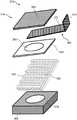
可选地,所述介质计量器包括安装在内置喷丸循环导管(也称为喷丸循环导管或导管)之内的流动分离器(flow separator)(例如介质过滤器(media filter))),以用于改变固体颗粒的分布模式。例如,流动分离器能够将喷丸流(例如固体颗粒)分散在一个或多个位于下游的喷丸循环导管处,特别是在流量传感器附近。特别地,流动分离器能够分散、扩散甚至部分阻挡快速移动的喷丸(例如固体颗粒),从而使快速移动的喷丸更一致地或均匀地分布在内置和外置喷丸循环导管的整个截面积上。例如,所述流动分离器包括一个鼓风机(blower)或空气压缩机(air compressor),其将加压空气流提供至喷丸,使喷丸分散或均匀分布。又例如,所述流动分离器具有对称的结构,以便更均匀地分散固体颗粒。Optionally, the media meter comprises a flow separator (eg a media filter) installed within a built-in shot peening circulation conduit (also referred to as a shot peening circulation conduit or conduit), for changing the distribution pattern of solid particles. For example, a flow separator can disperse the shot peening stream (eg, solid particles) at one or more downstream shot peening circulation conduits, particularly near the flow sensor. In particular, the flow separator is capable of dispersing, diffusing, and even partially blocking fast-moving shot peening (eg, solid particles), thereby allowing the fast-moving shot peening to be more uniformly or evenly distributed across the entire section of the internal and external shot peening circulation conduits area. For example, the flow separator includes a blower or air compressor that provides a flow of pressurized air to the shot peening, dispersing or uniformly distributing the shot peening. As another example, the flow separator has a symmetrical structure in order to disperse the solid particles more uniformly.
所述流动分离器可通过模具(moulding)的方式形成一个整体部件,也可通过组装(assembling)的方式形成一个分立部件。例如,流动分离器包括流动分离器顶部、流动分离器中部和流动分离器底部。流动分离器顶部和流动分离器底部分别安装在流动分离器中部和内部。更具体地说,流动分离器中部还可以包括通孔和延伸到通孔中的内部结构。所述流动分离器中部的内部结构还包括两个或更多的突出部分,一方面用于固定流动分离器底部,另一方面用于均匀分散固体颗粒。流动分离器底部还包括在一个或多个侧表面上的两个或多个开口(例如如细长的开口或槽),以用于均匀地散射固体颗粒。这些开口可以是均匀分布的。The flow separator can be formed as an integral part by moulding or as a discrete part by assembling. For example, a flow separator includes a flow separator top, a flow separator middle, and a flow separator bottom. The flow separator top and flow separator bottom are installed in the middle and inside of the flow separator, respectively. More specifically, the middle portion of the flow separator may further include through holes and internal structures extending into the through holes. The inner structure of the middle part of the flow separator also includes two or more protruding parts for fixing the bottom of the flow separator on the one hand and for uniformly dispersing the solid particles on the other hand. The flow separator bottom also includes two or more openings (eg, such as elongated openings or grooves) on one or more side surfaces for uniform scattering of solid particles. The openings can be evenly distributed.
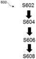
根据本申请的另一个方面,还公开了一种用于喷丸处理的介质配计量器的使用方法,其包括:首先,提供一种或多种喷丸处理介质;其次,将该一种或多种喷丸处理介质加速和减速至预定速度和/或流速;第三,测量该一种或多种喷丸处理介质的流速;最后,将该一种或多种喷丸处理介质引导至工件,以处理工件的表面。该方法的一些步骤可以按顺序组合、分离或改变。According to another aspect of the present application, there is also disclosed a method for using a media metering device for shot peening, which includes: first, providing one or more shot peening media; secondly, providing one or more shot peening media; A plurality of shot peening media are accelerated and decelerated to predetermined velocities and/or flow rates; third, the flow rate of the one or more shot peening media is measured; and finally, the one or more shot peening media are directed to the workpiece , to treat the surface of the workpiece. Some steps of the method may be combined, separated or varied in sequence.
可选地,所述喷丸处理介质或介质由本地或远程储存罐提供。喷丸处理介质可以是铁质、非铁质、或铁质和非铁质两种喷丸处理介质的组合。根据物件或工件的性质和工作要求来选择喷丸处理介质。当采用混合式喷丸处理介质时,可将不同的颗粒在储存罐中初步混合。或者,将两个或两个以上的储存罐与介质计量器的料斗相连,使每种类型的颗粒由各自的储存罐提供;然后将多种类型的颗粒在料斗内混合。Optionally, the shot peening medium or media is provided from a local or remote storage tank. The shot peening media can be ferrous, non-ferrous, or a combination of both ferrous and non-ferrous shot peening media. The shot peening medium is selected according to the nature and job requirements of the object or workpiece. When using mixed shot peening media, the different particles can be initially mixed in a storage tank. Alternatively, two or more storage tanks are connected to the hopper of the media meter so that each type of particle is supplied from a separate storage tank; the multiple types of particles are then mixed within the hopper.
喷丸介质在经过流量传感器之前,可以在循环导管中加速。根据喷丸机的类型,介质计量器可以是直压式(direct pressure-type)(即加压系统(pressurized system))或吸气式(suction-type)(即真空-吸气系统(vacuum-suction system))。对于前者,介质喷丸由加压空气推动,达到预定的速度;而对于后者,介质喷丸由真空-吸气杯产生的真空拉动。在逆向过程中,也可以通过所述直接压力型(即加压系统)或吸气型(即真空-吸气系统)在循环导管中以与预定的流速相反的方向使喷丸介质减速。另外,也可以通过部分关闭介质流动阀来降低流速,在这种情况下,由于颗粒和介质流动阀之间的碰撞,喷丸颗粒会失去一部分动量。The peening medium can be accelerated in the circulation conduit before passing through the flow sensor. Depending on the type of shot blasting machine, the media meter can be a direct pressure-type (ie a pressurized system) or a suction-type (ie a vacuum-suction system) suction system)). For the former, the media shot is propelled by pressurized air to a predetermined velocity; for the latter, the media shot is pulled by the vacuum created by the vacuum-suction cup. During the reverse process, the blasting medium can also be decelerated in the circulation conduit in the opposite direction to the predetermined flow rate by the direct pressure type (ie pressurized system) or suction type (ie vacuum-suction system). Alternatively, the flow rate can be reduced by partially closing the media flow valve, in which case the shot peening particles lose some of their momentum due to collisions between the particles and the media flow valve.
喷丸介质的流速可由流量传感器测量。流量传感器是根据所采用的介质类型来选择的,是铁质介质还是非铁质介质。如果需要使用铁质介质,则优选微波流量传感器。由微波流量传感器的发射器或收发器发出出射微波信号;然后与循环导管中经过的介质相遇。由于出射微波有一部分被反射回来,作为流量传感器的接收机或收发器接收到的入射微波信号,因此产生了反射微波信号。入射微波信号可以通过一个衰减器变弱或通过一个放大器变强,使入射微波信号落在测量图的线性区域内。The flow rate of the blasting medium can be measured by a flow sensor. The flow sensor is selected according to the type of medium used, whether it is ferrous or non-ferrous. Microwave flow sensors are preferred if the use of ferrous media is desired. The outgoing microwave signal is emitted by the transmitter or transceiver of the microwave flow sensor; it then meets the medium passing through the circulating conduit. Since a part of the outgoing microwave is reflected back, as the incident microwave signal received by the receiver or transceiver of the flow sensor, a reflected microwave signal is generated. The incident microwave signal can be weakened by an attenuator or strengthened by an amplifier so that the incident microwave signal falls within the linear region of the measurement map.
此外,测量喷丸介质的流速的步骤可选地包括安装、修理、修补、检查、测试或更换介质流量传感器,例如微波流量传感器。优选地,介质流量传感器可通过可拆卸的连接器容易地与循环导管脱离。如果再安装一个流量传感器作为冗余备份,则介质计量器可以连续工作。启动备份流量传感器,更换损坏的流量传感器,同时将损坏的流量传感器与循环导管脱钩,进行检查、修补或修复。在脱离过程中,介质计量器不会停止工作,从而大大提高了喷丸处理的效率。Additionally, the step of measuring the flow rate of the blasting medium optionally includes installing, repairing, repairing, inspecting, testing, or replacing a medium flow sensor, such as a microwave flow sensor. Preferably, the medium flow sensor is easily detachable from the circulation conduit by means of a detachable connector. If an additional flow sensor is installed as a redundant backup, the media meter can work continuously. Activate the backup flow sensor, replace the damaged flow sensor, and decouple the damaged flow sensor from the circulation conduit for inspection, repair or repair. During the disengagement process, the media meter will not stop working, which greatly improves the efficiency of shot peening.
物件或工件有时被放置在喷丸室的支架(bracket)上。支架适合于工件的形状和尺寸。循环导管的末端通常安装一个喷嘴(nozzle)。喷嘴可旋转,以用于将喷丸介质引导到工件上,以处理工件的表面。特别地,如果介质包括两种或多种类型的喷丸颗粒,分别用于同一工件,则可以安装多个喷嘴,每种类型的介质由其各自的喷嘴引导。例如,将第一喷嘴旋转至工件附近,含有大型喷丸颗粒的第一种介质通过第一喷嘴被引导至工件,进行第一种喷丸强化处理;然后在第一种喷丸处理完成后,将第一喷嘴旋转远离工件。接着,将第二喷嘴旋转到工件附近,将经过第二喷嘴的含有小型喷丸颗粒的第二介质对准工件进行第二种喷丸强化处理;然后在完成第二种喷丸处理后,将第二喷嘴旋转离开工件。在不停止介质计量器和更换喷嘴的情况下,可以进行第三或更多种喷丸强化过程。这样,介质计量器可以连续工作,大大提高了喷丸处理的效率。Objects or workpieces are sometimes placed on brackets in the blast chamber. The holder is adapted to the shape and size of the workpiece. A nozzle is usually installed at the end of the circulation conduit. The nozzle is rotatable for directing the blasting medium onto the workpiece to treat the surface of the workpiece. In particular, if the medium includes two or more types of blasting particles, each for the same workpiece, multiple nozzles may be installed, each type of medium being directed by its own nozzle. For example, the first nozzle is rotated to the vicinity of the workpiece, the first medium containing large shot peening particles is guided to the workpiece through the first nozzle, and the first shot peening treatment is performed; then after the first shot peening treatment is completed, Rotate the first nozzle away from the workpiece. Next, rotate the second nozzle to the vicinity of the workpiece, and align the second medium containing small shot peening particles passing through the second nozzle to the workpiece to perform the second shot peening treatment; then after the second shot peening treatment is completed, the The second nozzle rotates away from the workpiece. A third or more shot peening process can be performed without stopping the media meter and changing the nozzle. In this way, the media meter can work continuously, greatly improving the efficiency of shot peening.
可选地,所述使用介质计量器进行喷丸的方法还包括:自动调节至少一种喷丸介质的预定速度的步骤。该自动调整喷丸处理介质的预定速度的步骤是通过形成闭环控制系统来进行的。该闭环控制系统(又称反馈控制系统)一般采用将部分输出信号作为反馈信号反馈到输入端,以减少误差,提高控制系统的稳定性。例如,在连接到介质流动阀的可编程控制器中设置一个预设流量。如果检测到的流速高于该预设值,则可编程控制器将向介质流动阀发送一个减弱信号,以便相应地将介质流动阀关闭,流速因此降低。相反,如果检测到的流量低于预设值,则可编程控制器将向介质流动阀发送一个加强信号,以便相应地将阀门打开,流量因此增加。Optionally, the method of using a medium meter for shot peening further comprises the step of automatically adjusting the predetermined speed of at least one shot peening medium. The step of automatically adjusting the predetermined speed of the shot peening medium is performed by forming a closed loop control system. The closed-loop control system (also known as the feedback control system) generally uses part of the output signal as a feedback signal to feed back to the input end to reduce errors and improve the stability of the control system. For example, set a preset flow in a programmable controller connected to a medium flow valve. If the detected flow rate is higher than this preset value, the programmable controller will send a weakening signal to the medium flow valve to correspondingly close the medium flow valve, thereby reducing the flow rate. Conversely, if the detected flow rate is lower than the preset value, the programmable controller will send a boost signal to the medium flow valve to open the valve accordingly and the flow rate will increase accordingly.
可选地,当采用微波流量传感器作为介质计量器中的流量传感器时,测量一个或多个喷丸介质的流量的步骤还包括:利用(例如发射、接收)微波来检测(例如测量或检查)流量。微波流量传感器适用于检测基于多普勒效应的移动喷丸颗粒。例如,流量传感器或微波流量传感器可以安装在喷丸循环导管上,以便测量预定的速度或流量。Optionally, when a microwave flow sensor is used as the flow sensor in the media meter, the step of measuring the flow of one or more shot peening media further comprises: detecting (eg, measuring or inspecting) using (eg, transmitting, receiving) microwaves flow. Microwave flow sensors are suitable for detecting moving peening particles based on the Doppler effect. For example, a flow sensor or microwave flow sensor can be mounted on the peening circulation conduit to measure a predetermined velocity or flow.
可选地,测量一个或多个喷丸介质流速的步骤还包括:传输预定速度的数据。包括喷丸介质流速的操作信息可以显示或通过物联网(IoT)进行无线/有线传输,以用于远程传输、数据分析或诊断。Optionally, the step of measuring the flow rate of the one or more blast media further comprises: transmitting data of the predetermined velocity. Operational information including peening media flow rates can be displayed or wirelessly/wired via the Internet of Things (IoT) for remote transmission, data analysis or diagnostics.
可选地,当在介质计量器中采用微波流量传感器时,使用介质计量器进行喷丸的方法进一步包括:向喷丸介质产生(例如发射、发生或发射)微波以检查喷丸介质的流速的步骤。Optionally, when a microwave flow sensor is employed in the media meter, the method of using the media meter for shot peening further comprises: generating (eg, emitting, generating, or transmitting) microwaves to the shot peening medium to check the flow rate of the shot peening medium. step.
可选地,使用介质计量器进行喷丸的方法还包括:通过自动操作介质流动阀来调节流量的步骤。操纵或调节(例如衰减、增强、聚焦)微波的步骤,以用于测量一个或多个喷丸介质的流速。特别地,操纵(如衰减、增强、聚焦、过滤)微波的步骤包括:安装(如连接、移动、转移)微波反射器(microwave reflector)(如金属套筒(metal sleeve))或微波衰减器(microwave attenuator)(如塑料套筒(plastic sleeve)),以用于分别增强或衰减反射的微波信号。Optionally, the method of using a medium meter for shot peening further includes the step of adjusting the flow rate by automatically operating a medium flow valve. The step of manipulating or adjusting (eg, attenuating, enhancing, focusing) microwaves for use in measuring the flow rate of one or more peening media. Specifically, the step of manipulating (eg, attenuating, enhancing, focusing, filtering) microwaves includes installing (eg, attaching, moving, transferring) a microwave reflector (eg, a metal sleeve) or a microwave attenuator ( microwave attenuator) (such as a plastic sleeve) for enhancing or attenuating the reflected microwave signal, respectively.
可选地,使用介质计量器进行喷丸的方法还包括如下步骤:自动倾斜介质流动阀的顶板,以防止至少一种喷丸介质在介质流动阀处自动堆积或堵塞,例如通过安装介质计量器或介质计量阀。这样,顶板提供了非倾斜的表面,可防止在活动窗或顶板上的喷丸颗粒在重力作用下的积聚或堵塞。Optionally, the method of using a media meter for shot peening further comprises the step of automatically tilting the top plate of the media flow valve to prevent at least one shot peening medium from automatically accumulating or clogging at the media flow valve, for example by installing a media meter or medium metering valve. In this way, the top plate provides a non-sloping surface that prevents gravitational accumulation or clogging of shot peening particles on the movable window or top plate.
优选地,使用介质计量器进行喷丸的方法还包括:引导(如分散、散开、集中、聚焦、均匀分布、梳理、耙取)一个或多个喷丸介质的流动模式的步骤,以方便测量流速。Preferably, the method of blasting using a media meter further comprises the step of directing (eg, dispersing, spreading, concentrating, focusing, evenly distributing, combing, raking) the flow pattern of one or more blasting media to facilitate Measure the flow rate.
提供一种或多种喷丸处理介质的步骤有时还包括:改变一种或多种喷丸处理介质的步骤。例如,用铁质喷丸处理介质取代非铁质喷丸处理介质,或者说相反。可选地,改变一个或多个喷丸介质的步骤包括:调整介质计量器或流量传感器的操作参数。例如,如果将介质从非铁质喷丸改为铁质喷丸,则可降低流速,因为铁质喷丸介质具有较硬的特性。The step of providing one or more shot peening media sometimes also includes the step of changing one or more shot peening media. For example, replacing non-ferrous shot peening media with ferrous shot peening media, or vice versa. Optionally, the step of changing one or more of the blasting media includes adjusting an operating parameter of a media meter or flow sensor. For example, if the media is changed from non-ferrous to ferrous, the flow rate can be reduced due to the harder properties of ferrous media.
可选地,提供一种或多种喷丸介质的步骤还包括:通过喷丸机将一种或多种喷丸介质再循环的步骤。经过喷丸处理后的使用过的喷丸颗粒被收集到喷丸室中,然后转移到储存罐中。通过这种方式,可以为长时间操作连续提供喷丸介质。Optionally, the step of providing the one or more shot peening media further comprises the step of recycling the one or more shot peening media through the shot peening machine. The used shot peened particles after shot peening are collected in a shot peening chamber and then transferred to a storage tank. In this way, the blasting medium can be continuously supplied for prolonged operation.
可选地,将介质计量器用于喷丸处理的方法还包括:当检测到异常流速时,暂停并拉响喷丸计量器的警报(例如停止介质/介质流)的步骤。异常流速通过一个或多个指示器来通知介质计量器的操作人员。只有当流量调整到正常范围内后,才能恢复喷丸过程。Optionally, the method of using a media meter for shot peening further comprises the step of pausing and sounding an alarm of the shot peening meter (eg stopping the media/media flow) when an abnormal flow rate is detected. The operator of the media meter is notified by one or more indicators of abnormal flow rates. The shot peening process can be resumed only when the flow rate is adjusted to within the normal range.
根据本申请的另一个方面,还公开了一种用于喷丸的介质计量器的制作或组装方法,该制作或组装方法包括:提供用于测量固体颗粒(也称为喷丸流或固体颗粒)流速的固体流量传感器或流量传感器;然后用连接器(例如可拆卸连接器)将流量传感器耦合到喷丸机的喷丸循环导管。例如,耦合微波流量传感器的步骤包括:将微波流量传感器连接到喷丸循环导管。According to another aspect of the present application, there is also disclosed a method of making or assembling a media meter for shot peening, the making or assembling method comprising: providing a method for measuring solid particles (also known as shot peening flow or solid particle ) solids flow sensor or flow sensor for flow rate; the flow sensor is then coupled with a connector (eg, a detachable connector) to the shot peening circulation conduit of the shot peening machine. For example, the step of coupling the microwave flow sensor includes connecting the microwave flow sensor to the shot peening circulation conduit.
可选地,制造或组装用于喷丸的介质计量器的方法还包括:引导、改变或调整固体颗粒的流动模式的步骤。特别地,通过第一分散器、第二分散器或两者均有,将铁质喷丸介质的聚集模式改变为分散模式。可选地,引导、改变或调整固体颗粒的流动模式的步骤还包括:用一个或多个第一分散器(例如筛子)使固体喷丸介质(即介质)分散、变形或散布的程序。Optionally, the method of manufacturing or assembling a media meter for shot peening further comprises the step of directing, changing or adjusting the flow pattern of the solid particles. Specifically, the aggregation mode of the ferrous shot peening medium is changed to a dispersion mode by the first disperser, the second disperser, or both. Optionally, the step of directing, altering or adjusting the flow pattern of the solid particles further comprises a procedure of dispersing, deforming or spreading the solid blasting medium (ie medium) with one or more first dispersers (eg screens).
可选地,当在介质计量器中采用微波流量传感器时,用于喷丸处理的介质计量器的制作或组装方法还包括:用信号调节器调节流量传感器的微波信号强度的步骤。反射的微波信号可以是衰减的,也可以是放大的。Optionally, when a microwave flow sensor is used in the medium meter, the method for manufacturing or assembling the medium meter for shot peening further includes the step of adjusting the microwave signal intensity of the flow sensor with a signal conditioner. The reflected microwave signal can be attenuated or amplified.
可选地,用于喷丸的介质计量器的制作或组装方法还包括:将套筒连接到喷丸循环导管的一部分,例如循环导管的内壁,以吸收、反射或增强微波信号的步骤。Optionally, the method of making or assembling a medium meter for shot peening further includes the step of connecting the sleeve to a portion of the shot peening circulation conduit, such as the inner wall of the circulation conduit, to absorb, reflect or enhance the microwave signal.
在一些实施例中,制造或组装用于喷丸的介质计量器的方法还包括:通过诸如观察窗的监控系统从视觉上检查介质计量器的步骤。In some embodiments, the method of manufacturing or assembling a media gauge for shot peening further includes the step of visually inspecting the media gauge through a monitoring system such as a viewing window.
在一些实施例中,用于喷丸处理的介质剂量器的制造或装配方法还包括:将介质流动阀安装到喷丸循环导管上以调节流量的步骤。介质流动阀可以安装在主支路上,也可以安装在一个侧支路上。此外,介质流动阀也可以垂直安装或与喷丸循环导管成一定角度安装。In some embodiments, the method of manufacturing or assembling a media doser for shot peening further includes the step of installing a media flow valve on the shot peening circulation conduit to regulate flow. The medium flow valve can be installed on the main branch or on a side branch. In addition, the media flow valve can also be installed vertically or at an angle to the peening circulation duct.
优选地,用于喷丸的介质计量器的制造或组装方法还包括:倾侧或倾斜介质流动阀的顶板的步骤,以防止固体颗粒在顶板处堆积。这样,顶板提供了非水平的表面,可防止喷丸颗粒在重力作用下在活动窗或顶板处堆积或堵塞。Preferably, the method of manufacturing or assembling a medium meter for shot peening further comprises the step of tilting or tilting the top plate of the medium flow valve to prevent accumulation of solid particles at the top plate. In this way, the top plate provides a non-horizontal surface that prevents gravitational buildup or clogging of shot peening particles at the movable window or top plate.
可选地,制造或组装用于喷丸处理的介质计量器的方法还包括:更换介质计量器的至少一个部件(例如分散器)的步骤。例如,分散器可以是流量传感器的第一分散器或介质流动阀的第二分散器。通过这种方式,所述介质计量器可以连续工作,从而提高生产率。Optionally, the method of manufacturing or assembling a media meter for shot peening further comprises the step of replacing at least one component of the media meter (eg, the disperser). For example, the disperser may be the first disperser of the flow sensor or the second disperser of the medium flow valve. In this way, the media meter can work continuously, thereby increasing productivity.
根据本申请的另一个方面,还公开了一种介质流动阀的制作或组装方法。该制作或组装方法包括:首先,提供具有第一通孔的基板;其次,在基板上安装具有第二通孔的底板;第三,在底板上安装阀控滑轮;最后,在阀控滑轮上安装顶板。这些步骤中的一些步骤可以组合、分离或改变顺序。According to another aspect of the present application, a method for manufacturing or assembling a medium flow valve is also disclosed. The manufacturing or assembling method includes: first, providing a base plate with a first through hole; secondly, installing a base plate with a second through hole on the base plate; third, installing a valve control pulley on the base plate; finally, installing a valve control pulley on the base plate Install the top plate. Some of these steps may be combined, separated or changed in order.
可选地,介质流动阀的制作或组装方法还包括以下步骤:在基板和底板之间安装用于使喷丸颗粒变形流动的第二分散器。Optionally, the manufacturing or assembling method of the medium flow valve further includes the following steps: installing a second disperser between the base plate and the bottom plate for deforming and flowing the shot peening particles.
可选地,介质流动阀的制作或组装方法还包括:更换介质导流器的第一分散器或介质流动阀的第二分散器的步骤。为了达到相同散射介质的目的,第一分散器和第二分散器可以交替使用;因此,即使第一分散器或第二分散器中的任何一个不能正常工作,配备有介质导流器和介质流动阀的介质计量器也可以连续运行,以提高生产率。Optionally, the manufacturing or assembling method of the medium flow valve further includes the step of replacing the first disperser of the medium flow guide or the second disperser of the medium flow valve. For the purpose of achieving the same scattering medium, the first disperser and the second disperser can be used alternately; thus, even if either the first disperser or the second disperser fails to work properly, the medium guide and the medium flow are equipped The valve's media meter can also run continuously to increase productivity.
根据另一个方面,本申请提供了一种用于调节或控制喷丸处理的介质计量器的控制阀(control valve)。所述控制阀基本包括:带有第一通孔的基板、放置在基板上的带有第二通孔的底板、安装在底板上的阀控滑轮,以及放置在阀控滑轮上并位于底板上的顶板。该控制阀还可在基板和底板之间包括用于使铁质喷丸流动变形(如改变分布或流动模式)的网状物(mesh),使其适用于铁质喷丸。According to another aspect, the present application provides a control valve for adjusting or controlling a media meter for shot peening. The control valve basically includes: a base plate with a first through hole, a base plate with a second through hole placed on the base plate, a valve control pulley mounted on the base plate, and a valve control pulley placed on the base plate and located on the base plate the top plate. The control valve may also include a mesh between the base plate and the bottom plate for flow deformation (eg, changing the distribution or flow pattern) of the ferrous shot, making it suitable for ferrous shot.
根据另一个方面,本申请提供的介质计量器还包括微波测量单元,如微波传感器,用于测量喷丸的流量,此外还包括调节喷丸流量的控制阀。微波测量单元通常与电源、控制输出、警报输出和可选的模拟输出连接。According to another aspect, the medium meter provided by the present application further includes a microwave measuring unit, such as a microwave sensor, for measuring the flow rate of shot peening, and further includes a control valve for adjusting the flow rate of shot peening. Microwave measurement units are typically connected with power, control outputs, alarm outputs and optional analog outputs.
附图说明Description of drawings
附图(图)示出了实施例并且用于解释所公开实施例的原理。然而,应该理解,这些图仅出于说明的目的,而不是用于限定相关发明。The drawings (diagrams) illustrate embodiments and serve to explain the principles of the disclosed embodiments. It should be understood, however, that these figures are for illustrative purposes only and are not intended to limit the related invention.
图1示出第一介质计量器;Figure 1 shows a first medium meter;
图2示出微波收发器的示意图;Figure 2 shows a schematic diagram of a microwave transceiver;
图3示出铸造钢丸的规格;Figure 3 shows the specifications of the cast steel shot;
图4示出调质(conditioned)碳钢切割线喷丸的规格;Figure 4 shows the specifications of conditioned carbon steel cutting wire shot peening;
图5示出调质(conditioned)不锈钢切割线喷丸的规格;Figure 5 shows specifications for shot peening of conditioned stainless steel cutting lines;
图6示出淬硬(hardened)钢喷丸的规格;Figure 6 shows specifications for hardened steel shot peening;
图7示出玻璃珠喷丸的规格;Figure 7 shows the specifications of glass bead peening;
图8示出陶瓷珠喷丸的规格;Figure 8 shows the specifications of ceramic bead peening;
图9示出第二介质计量器;Figure 9 shows a second medium meter;
图10示出第三介质计量器;Figure 10 shows a third medium meter;
图11示出第三介质计量器的分解图;Figure 11 shows an exploded view of the third medium gauge;
图12示出第三介质计量器的第一介质流动阀;Figure 12 shows the first medium flow valve of the third medium meter;
图13示出第三介质计量器的第二介质流动阀;Figure 13 shows the second medium flow valve of the third medium meter;
图14示出介质流动阀的第一实施例的分解图;Figure 14 shows an exploded view of the first embodiment of the medium flow valve;
图15示出介质流动阀的第二实施例的分解图;Figure 15 shows an exploded view of the second embodiment of the medium flow valve;
图16示出介质流动阀的双层网;Figure 16 shows a two-layer mesh of a medium flow valve;
图17示出介质流动阀的双层网及垫片(spacer);Figure 17 shows the double layer mesh and spacer of the medium flow valve;
图18示出使用第三介质计量器的一个介质流动阀的测试图;Figure 18 shows a test chart of a media flow valve using a third media meter;
图19示出使用第三介质计量器的另一个介质流动阀的测试图;Figure 19 shows a test chart of another medium flow valve using a third medium meter;
图20示出一种使用用于喷丸处理的介质计量器;Figure 20 illustrates the use of a media meter for shot peening;
图21示出一种用于喷丸处理的介质计量器的制作或组装方法;Figure 21 shows a method of making or assembling a media meter for shot peening;
图22示出一种介质流动阀的制作或组装方法;以及Figure 22 shows a method of making or assembling a medium flow valve; and
图23示出一种维护介质计量器的方法。Figure 23 shows a method of maintaining a media gauge.
图中标号示意如下:The symbols in the figure are as follows:
100、第一介质计量器;102、料斗;104、中空圆柱体;106、中空导管;108、计算设备;110、核心组件;112、微波收发装置;113孔洞;114、喷丸介质;116、锥形件;118、电磁铁;120、永磁体;122、外壳;124、顶点;126、底座;128、支柱;130、第一支柱;132、第二支柱;134、第三支柱;136、接头;138、盖子;140、圆形开口;142、微波发生器;144、微波传感器;146、反射放大器;148、电源;150、介质流方向;152、算法/物质流速;154、中空管;156、入射束;158、反射束;160、微波收发器;162、调制器;164、本机振荡器;166、混频器;168、调谐螺钉;169、波导器;170、变容二极管;172、耿氏二极管;174、腔体;176、腔调谐螺丝;178、微波通透器(虹膜);180、耿氏发射器;182、流体;200、第二介质计量器;202、料斗;204、中空圆柱体;206、中空导管;208、计算设备;210、核心组件;212、微波收发装置;213、孔洞;214、喷丸介质;218、电磁铁;236、接头;242、微波发生器;244、微波传感器;246、反射放大器;250、介质流动方向;252、算法;254、中空管;256、入射束;258、反射束;260、微波收发器;284、螺丝螺纹;286、水平面;300、第三介质计量器;302、壳体;304、微波流量传感器;306、喷丸循环导管;308、传感器连接器;310、传感器检测主体;312、微波传感器感测头;314、传感器导向器;316、介质流动阀;318、阀体;320、阀杆;322、步进电机;324、阀门连接器;326、距离传感器;328、介质入口;330、介质出口;332、介质过滤器;334、主控制器电路板;336、阀门连接器侧板;338、开口;340、距离传感器安装装置;342、橡胶硅;344、调节销;346、特氟龙滑动轴承衬套;348、流动分离器;350、流动分离器顶部;352、流动分离器中部;354、流动分离器底部;356、法兰盖;358、第一装配式介质流动阀;360、基板;362、网状物;364、底板;366、阀控滑轮;368、顶板;370、第二装配式介质流动阀;372、长部;374、短部;376、介质流动阀的第一实施例;378、第一通孔;380、第二通孔;382、方形开口;384、介质流动阀的第二实施例;386、第一双层网;388、顶网;390、底网;392、第二双层网;394、垫片;396、第一图形;398、第二图形;399、接口;400、使用第三介质计量器的方法;S402、方法400的第一步骤;S404、方法400的第二步骤;S406、方法400的第三步骤;S408、方法400的第四步骤;500、制造或组装第三介质计量器的方法;S502、方法500的第一步骤;S504、方法500的第二步骤;600、制造或组装介质流动阀的方法;S602、方法600的第一步骤;S604、方法600的第二步骤;S606、方法600的第三步骤;S608、方法600的第四步骤;700、维护介质计量器的方法;S702、方法700的第一步骤;S704、方法700的第二步骤;800、第三通孔;802、第四通孔;804、内部结构;806、第一突出部;808、第二突出部;810、第三突出部;812、第四突出部;814、圆柱形侧表面;816、第一细长开口;818、第二细长开口;820、第三细长开口;822、第四细长开口。100, first medium meter; 102, hopper; 104, hollow cylinder; 106, hollow conduit; 108, computing equipment; 110, core assembly; 112, microwave transceiver; 113 holes; 114, shot peening medium; 116, Conical piece; 118, electromagnet; 120, permanent magnet; 122, shell; 124, vertex; 126, base; 128, strut; 130, first strut; 132, second strut; 134, third strut; 136, Connector; 138, lid; 140, circular opening; 142, microwave generator; 144, microwave sensor; 146, reflection amplifier; 148, power supply; 150, medium flow direction; 152, algorithm/material flow rate; 154, hollow tube ; 156, incident beam; 158, reflected beam; 160, microwave transceiver; 162, modulator; 164, local oscillator; 166, mixer; 168, tuning screw; 169, waveguide; 170, varactor diode ; 172, Gunn diode; 174, cavity; 176, cavity tuning screw; 178, microwave transparent device (iris); 180, Gunn transmitter; 182, fluid; 200, second medium meter; 202, hopper ; 204, hollow cylinder; 206, hollow conduit; 208, computing equipment; 210, core components; 212, microwave transceiver; 213, hole; 214, shot peening medium; 218, electromagnet; 236, joint; 242, microwave generator; 244, microwave sensor; 246, reflection amplifier; 250, medium flow direction; 252, algorithm; 254, hollow tube; 256, incident beam; 258, reflected beam; 260, microwave transceiver; 284, screw thread; 286, horizontal plane; 300, third medium meter; 302, housing; 304, microwave flow sensor; 306, shot peening circulation conduit; 308, sensor connector; 310, sensor detection body; 312, microwave sensor sensor head; 314, sensor guide; 316, medium flow valve; 318, valve body; 320, valve stem; 322, stepper motor; 324, valve connector; 326, distance sensor; 328, medium inlet; 330, medium outlet; 332 334, main controller circuit board; 336, valve connector side plate; 338, opening; 340, distance sensor installation device; 342, rubber silicon; 344, adjusting pin; 346, Teflon sliding bearing bushing sleeve; 348, flow separator; 350, top of flow separator; 352, middle of flow separator; 354, bottom of flow separator; 356, flange cover; 358, first assembled medium flow valve; 360, base plate; 362 364, bottom plate; 366, valve control pulley; 368, top plate; 370, second assembled medium flow valve; 372, long part; 374, short part; 376, the first embodiment of the medium flow valve; 378, the first through hole; 380, the second through hole; 382, square opening; 384, the second embodiment of the medium flow valve; 386, the first double-layer mesh; 388, the top mesh; 390, the bottom mesh; 392, the second double-layer mesh; 394, the gasket; 396, the first 398, the second graph; 399, the interface; 400, the method of using the third medium meter; S402, the first step of the method 400; S404, the second step of the method 400; S406, the third step of the method 400 ; S408, the fourth step of the method 400; 500, the method of manufacturing or assembling the third medium meter; S502, the first step of the method 500; S504, the second step of the method 500; method; S602, the first step of the method 600; S604, the second step of the method 600; S606, the third step of the method 600; S608, the fourth step of the method 600; 700, the method of maintaining the medium meter; S702, the method The first step of 700; S704, the second step of the method 700; 800, the third through hole; 802, the fourth through hole; 804, the internal structure; 806, the first protrusion; 808, the second protrusion; 810, 812, fourth protrusion; 814, cylindrical side surface; 816, first elongated opening; 818, second elongated opening; 820, third elongated opening; 822, fourth elongated opening .
具体实施方式Detailed ways
现在将参考上述附图描述本申请的示例性的、非限制性的实施例。Exemplary, non-limiting embodiments of the present application will now be described with reference to the above figures.
图1至图8示出了本申请的第一实施例。特别地,图1示出了第一介质计量器100的截面图。第一介质计量器100包括料斗102、中空圆柱体104、中空导管106和计算设备108。中空圆柱体104还包括核心组件110。中空导管106还包括微波收发装置112。1 to 8 illustrate a first embodiment of the present application. In particular, FIG. 1 shows a cross-sectional view of a
参照图1,从上往下,料斗102是一个连接在中空圆柱体104上端的圆形漏斗。料斗102的内斗直径约为四十毫米(40mm),外斗直径为四十四毫米(44mm)。中空圆柱体104的长度为一百毫米(100毫米),其内体直径为十六毫米(16毫米),外体直径为二十毫米(20毫米)。中空圆柱体104是一个站立的、直的中空圆柱体,沿其弧形表面有一个孔洞113。中空圆柱体104的内部是一个通道,该通道允许喷丸介质114从上端输送到下端,或从上端输送到下端;所述喷丸介质114是不同类型的喷丸颗粒,铁质和非铁质。Referring to FIG. 1 , from top to bottom, the
核心组件110位于料斗102的内空区域。核心组件110包括一个锥形件116、一个或多个绕在金属线上的电磁铁118、一个永磁体120和一个外壳122。锥形件116的顶点124指向中空圆柱体104。永磁体120粘附在锥形件116的底座126的中间。两个电磁铁118与永磁体120相邻。外壳122包裹永久磁铁120,两个电磁铁118与锥形件116形成相邻的外表面。外壳122的形状像一个被倒置的圆柱形盖子,并覆盖永磁体120和两个电磁体118。The
永磁体120是一个矩形块。如图1所示的两块电磁铁118用金属线盘绕并与永磁体120相邻。另外,可以使用两个以上的电磁铁118,例如,可以将四个电磁铁118以北-南-东-西(NSEW)定位来围绕永磁铁120。四个电磁铁118和锥形件116上方的一个永磁体120被安置在一个非磁性材料外壳122中,该外壳122包含了电磁铁118和永磁体120。锥形件116与磁体(电磁铁118和永磁体120)一起构成一个核心组件110。核心组件110处于悬浮位置,不与中空圆柱体104的壁相接触,其允许喷丸介质114流过所述通道。核心组件110由三个支柱128(未示出)来支撑,所述三个支柱128横跨在中空圆柱体104的内侧周壁(inner peripherywall)与核心组件110的外壳122之间。这三个支柱128的间距相等,从中空圆柱体104的上端看,第一支柱130的第一角度为0°,第二支柱132的第二角度为120°,第三支柱134的第三角度为240°。同时,另一种选择是使用圆柱形永磁体120代替矩形永磁体120。The
孔洞113位于中空圆柱体104的中部。中空导管106与中空圆柱体104的孔洞113正交连接。中空导管106的长度约为三十毫米(30mm),其外径为二十毫米(20mm),内径为十六毫米(16mm)。中空导管106的第一端与中空圆柱体104的孔洞113正交地连接或切口而形成接头136。第二端或相反端有一个盖子138,中心有一个圆形开口140。盖子138与第二端牢固地结合在一起。圆形开口140的内径为十七毫米(17mm)。圆形开口螺丝的内侧周边具有螺纹。第一介质计量器100由金属制成,特别是SUS304 18/8不锈钢,其含有百分之十八(18%)的铬(chromium)和百分之八(8%)的镍(nickel)。The hole 113 is located in the middle of the
微波收发装置112固定在中空导管106的第二端。微波收发装置112包括微波发生器142、微波传感器144。然后将检测到的反射微波信号发送到计算设备108。微波传感器144还包括一个反射放大器146。微波传感器144能够承受与其正常工作温度相差达5摄氏度的温度波动。热量增加是由于喷丸介质114之间的碰撞以及当喷丸介质114沿着中空圆柱体104移动时与中空圆柱体104的内侧周壁碰撞的结果。The
微波是一种波长从一米到一毫米的电磁辐射,频率在300兆赫(MHz)(波长100厘米)到300千兆赫((GHz))(波长0.1厘米)之间。微波收发器142工作在K波段,频率范围为18至26.5千兆赫(GHz)。Microwaves are electromagnetic radiation with wavelengths ranging from one meter to one millimeter, with frequencies between 300 megahertz (MHz) (
微波收发装置112的容许工作温度范围为-20℃至+80℃。允许的最大压力为0.5兆帕斯卡(Mega Pascal(MPa))。仅仅为了说明和比较微波收发装置112可接受的相对压力,大气压力(atmospheric pressure(atm))为0.101兆帕斯卡(MPa)。微波收发装置112的侵入防护等级为IP65,这与固体颗粒防护有关,并且防尘。来自市电的电源(240Vac 50Hz)供给微波收发装置112。The allowable operating temperature range of the
第一介质计量器100在其空闲状态下(即没有电流流过绕线),由于永磁体120的磁场存在,所以喷丸介质114不能自由地流过通道。为了使喷丸介质114能够自由地流过通道,电力通过缠绕在一个或多个电磁铁118上的金属线,从而抵消了永磁体120所施加的磁场。具体而言,绕在四个电磁铁118上的四根导线从外壳122的顶侧(未示出)连接到第一介质计量器(100)之外的电源148。电磁铁118的磁场由流经导线的电流控制,并由计算设备108控制。每个单独的电磁铁118的电流可以单个、成对、三个或全部控制。In its idle state (ie, no current is flowing through the winding), the peening medium 114 cannot flow freely through the channel due to the presence of the magnetic field of the
替代地,永磁体120也可以是圆柱形磁体。另外四个电磁铁118也可以用金属线缠绕的一个圆形电磁铁代替。Alternatively, the
图2示出了微波收发器(microwave transceiver)160的示意图,其包括一个调制器(modulator)162、一个本机振荡器(local oscillator)164、一个混频器(mixer)166和多个调谐螺钉168。调制器162显示在左上角,本机振荡器164显示在右上角,混频器166显示在右下角,调谐螺钉168显示在左下角。微波收发器160中所示的元件展示了主要模块,现解释为限制在特定的位置上。2 shows a schematic diagram of a microwave transceiver 160, which includes a
电路中的变容二极管(varicap diode)170与调谐电路(tuned circuit)相连,通常与现有电容或电感并联。必须在变容二极管170上施加反向偏置的直流电压,以改变其电容,且必须阻止其进入调谐电路。实现这一目的的方法是,将一个电容比变容二极管170的最大电容还大100倍左右的直流阻断电容(DC blocking capacitor)与其串联,并将高阻抗源(high impedance source)的直流电施加到变容阴极(varicap cathode)和阻断电容之间的节点上,如左上角所示的断线椭圆。A
耿氏二极管(Gunn diode)172又称转移电子器件(transferred electron device(TED)),是二极管的一种形式,是一种双端无源半导体电子元件,具有负电阻,用于高频电子器件。耿氏振荡器(Gunn oscillators)作为本机振荡器164使用,如介质计量器右上角断线框所示。耿氏二极管172安装在一个腔体174中,该腔体174被调谐为以二极管基本频率的两倍进行谐振。腔体174的长度可通过千分尺(micrometer)调节(腔调谐螺丝176)来改变。在连接到混频器166之前,本机振荡器164通过一个10dB衰减器(attenuator)(未显示)连接。当本机振荡器164用于接收器时,由于只需产生的功率(5mW到20mW)的一小部分用来操作混频器166(0.5到1mW),其余的功率被耗散在一个匹配的负载中,从而实现匹配。本机振荡器164可以通过一个10~15dB的衰减器或通过一个定向耦合器(directional coupler)(未示出)向混频器166输入一个假负载(dummy load)。
耦合本机振荡器164到腔体174的微波通透器(虹膜)178的大小是这样的,当其一起被调谐时,本机振荡器164的输出最多可减少约三分之一(即约2dB)。The microwave translucent (iris) 178 that couples the
多个混频二极管(mixer diode)的设计是为了尽可能有效地将包括微波在内的射频(radio frequency(RF))转换为中频(intermediate frequency)。原因是在射频频率上的选择放大器(selective amplifier)比较昂贵,因此,信号被转换到可以实现高增益和良好选择性的较低频率。频率转换是通过以本机振荡器164确定的速率开启和关闭一个响应快、截止频率高的混频二极管的开关而实现的。然后,输出频率就是本机振荡器164的频率与射频频率之差。Multiple mixer diodes are designed to convert radio frequencies (RF), including microwaves, to intermediate frequencies as efficiently as possible. The reason is that selective amplifiers are more expensive at radio frequencies, so the signal is converted to lower frequencies where high gain and good selectivity can be achieved. Frequency translation is accomplished by switching a fast-response, high-cut-off frequency mixing diode switch on and off at a rate determined by the
二极管双平衡混频器(diode double-balanced mixer)包含两个或两个以上的不平衡-平衡变压器(unbalanced-to-balanced transformer)和一个由4×n个二极管组成的二极管环,其中n是二极管环中每个脚所含二极管的数量。每个脚通常由最多四个二极管组成。输入和输出端口--通常被命名为本机振荡器164、射频(RF)或信号,以及连接DBM与其相关电路的中频(IF)。A diode double-balanced mixer consists of two or more unbalanced-to-balanced transformers and a diode ring consisting of 4 × n diodes, where n is The number of diodes contained in each leg of the diode ring. Each leg usually consists of up to four diodes. Input and output ports--often named
5个传输线变压器(transmission-line transformer)和2个肖特基四环(Schottky-quad ring)组成双双平衡混频器(double double-balanced mixer(DDBM)),如右下角断线框所示。与单环设计相比,这种设计可以提供更低的失真、更好的信号处理能力和更高的端口间隔离(interport isolation)。Five transmission-line transformers and two Schottky-quad rings form a double double-balanced mixer (DDBM), as shown by the broken line in the lower right corner. This design can provide lower distortion, better signal processing capability, and higher interport isolation than a single-loop design.
单二极管环(single-diode-ring)DBM的一个延伸是双双平衡混频器(doubledouble-balanced mixer(DDBM)),其比单环设计具有高动态范围和更强的信号处理能力。双双平衡混频器(DDBM)采用传输线变压器(transmission-line transformer)和两个二极管环(diode ring)。这种类型的混频器比DBM有更高的1-dB压缩点(1-dB compressionpoint)(通常比本机振荡器驱动低3到4dB)。低失真是双双平衡混频器(DDBM)的典型特征。根据所使用的铁氧体磁芯材料,可覆盖低至几百赫兹、高至几千兆赫(GigaHertz)的频率。An extension of the single-diode-ring DBM is the double double-balanced mixer (DDBM), which has higher dynamic range and greater signal processing capabilities than single-ring designs. A double double balanced mixer (DDBM) uses a transmission-line transformer and two diode rings. This type of mixer has a higher 1-dB compression point than a DBM (typically 3 to 4 dB lower than a local oscillator drive). Low distortion is typical of double double balanced mixers (DDBMs). Depending on the ferrite core material used, frequencies as low as a few hundred hertz and as high as several gigahertz (GigaHertz) can be covered.
多个调谐螺丝168(在左下角的断线圆圈中所示)提供了一个响应式(reactive)(与被动式(passive)相反)元件。当螺丝稍稍推进到波导器(waveguider)169中或完全没有推进时也称为第一位置时,其成为电容。当螺丝完全推进到波导器169中时,称为第二位置,它成为波导器169的电感。当螺丝在上述两个位置之间调整时,也称为第三位置,它成为一个谐振LC(电感-电容)电路。A number of tuning screws 168 (shown in the broken line circle in the lower left corner) provide a reactive (as opposed to passive) element. When the screw is pushed into the
喷丸介质114与流体182的混合物从中空圆柱体104的上端高速移动到下端。流体182是来自压缩机(未示出)的加压空气。喷丸介质114的混合物由一个或多个料斗102送入中空圆柱体104,料斗102位于中空圆柱体104的上端。喷丸介质114可以包括铁质介质和非铁质介质。另外,空气也可以从中空圆柱体104的具有真空的底端抽出。The mixture of blasting medium 114 and fluid 182 moves at high velocity from the upper end of the
图3、图4、图5、图6为四个表格,显示了与铁质介质有关的不同介质类型和尺寸的形状要求。图3为铸钢喷丸(cast steel shot)的规格,图4为调质(conditioned)碳钢切割线喷丸的规格,图5是调质(conditioned)不锈钢切割线喷丸的规格,图6是淬硬(hardened)钢喷丸的规格。Figures 3, 4, 5, and 6 are four tables showing shape requirements for different media types and sizes related to ferrous media. Fig. 3 is the specification of cast steel shot, Fig. 4 is the specification of conditioned carbon steel cutting line shot peening, Fig. 5 is the specification of conditioned stainless steel cutting line shot peening, Fig. 6 It is the specification of hardened steel shot peening.
铁质介质的种类和尺寸符合以下规格,满足汽车工程师协会(Society ofAutomotive Engineers)AMS 2430、AMS 2431和AMS 2432的要求。The types and sizes of ferrous media meet the following specifications and meet the requirements of Society of Automotive Engineers AMS 2430, AMS 2431 and AMS 2432.
铸钢喷丸(ASR/ASH70-ASR/ASH930),其中根据AMS2431/1,ASR为普通硬度;根据AMS2431/2,ASH为高硬度,数字描述的喷丸尺寸如图3所示。Cast steel shot peening (ASR/ASH70-ASR/ASH930), according to AMS2431/1, ASR is ordinary hardness; according to AMS2431/2, ASH is high hardness, and the shot peening size described by numbers is shown in Figure 3.
调质(conditioned)碳钢切割线喷丸(AWCR/AWS2-AWCR/AWS116),其中AWCR根据AMS2431/3D涉及调质(conditioned)碳钢切割线喷丸,如图4所示;AWS根据AMS2431/4C涉及调质(conditioned)不锈钢切割线喷丸,如图5所示;以及如图6所示,根据AMS2431/5(APB7/16-APB3/32)的淬硬(hardened)钢喷丸。Shot peening of conditioned carbon steel cutting lines (AWCR/AWS2-AWCR/AWS116), where AWCR involves shot peening of conditioned carbon steel cutting lines according to AMS2431/3D, as shown in Figure 4; AWS according to AMS2431/ 4C involves shot peening of conditioned stainless steel cutting lines, as shown in Figure 5; and hardened steel shot peening according to AMS2431/5 (APB7/16-APB3/32), as shown in Figure 6.
图7和图8是两张表格,显示了与非铁质介质有关的不同介质类型和尺寸的形状要求。图7是玻璃珠的规格,图8是陶瓷珠的规格。Figures 7 and 8 are two tables showing the shape requirements for different media types and sizes in relation to non-ferrous media. Figure 7 shows the specifications of glass beads, and Figure 8 shows the specifications of ceramic beads.
非铁质介质的种类和尺寸符合下列规格,满足SAE AMS 2430、AMS 2431和AMS2432的要求。The types and sizes of non-ferrous media meet the following specifications and meet the requirements of SAE AMS 2430, AMS 2431 and AMS2432.
如图7所示,根据AMS2431/6-AGB 6至AGB 200的玻璃珠;以及如图8所示,根据AMS2431/7-AZB 100至AZB 850的陶瓷珠。As shown in Figure 7, glass beads according to AMS2431/6-
喷丸介质114通过中空圆柱体104的低流速范围为0.5~15公斤/分钟(kg/min)或2.2~28.6磅/分钟(lb/min)。The low flow rate of shot peening medium 114 through
喷丸介质114通过中空圆柱体104的高流速范围为100~300公斤/分钟(kg/min)或220.46~661.38磅/分钟(lb/min)。The high flow rate of shot peening medium 114 through
图9示出了第二实施例,提供了第二介质计量器200的横截面图。第二介质计量器200包括站立的、直的中空圆柱体204,其沿其弯曲的表面设有孔洞213,以及与所述中空圆柱体204的孔洞213以一定角度连接的中空导管206,形成Y形配置。A second embodiment is shown in FIG. 9 , providing a cross-sectional view of a
中空导管206的第一端与中空圆柱体204的孔洞213连接或切口,形成一个接头236,而第二端或相反端则暴露在外。中空体的暴露的第二端有一个内侧周边,其具有含螺纹的螺丝。中空导管206的第一端相对于水平面286形成二十度角(20°)。中空导管206的第一端相对于竖直的中空圆柱体204,在自上而下的轴线上有两个半月形(half-moon)的轮廓。The first end of the hollow conduit 206 is connected or cut out with the hole 213 of the
另一种选择是将直棘轮杆(straight ratcheted rod)的一端连接到铰链的另一侧。直棘轮杆的第二端与一个齿轮啮合。该齿轮由一个电动机驱动。电动机由计算设备108控制。Another option is to attach one end of a straight ratcheted rod to the other side of the hinge. The second end of the straight ratchet lever is engaged with a gear. The gear is driven by an electric motor. The motor is controlled by computing
第二介质计量器200包括与第一介质计量器100相似或相同的部件。在此,在相关和适当的情况下,通过引用而对类似或相同部件进行描述。The second
第一介质计量器100和第二介质计量器200提供了监测颗粒的移动速度和识别通过中空圆柱体104或204的颗粒类型的方法。The
中空的圆柱体104或204和中空导管106或206由不锈钢制成,以承受其中的喷丸介质或介质114或214的较高运行速度。The
对于第一介质计量器100,中空导管106与中空圆柱体104正交连接,以防止喷丸介质114损坏微波收发装置112。微波发生器142使用一个耿氏二极管172,其用于微波频率及以上。耿氏二极管172用于振荡器,但也用于微波放大器,以放大信号。耿氏二极管172是一个单端口(one-port)(两个终端(terminal))的器件,因此,一个放大电路将输出的放大信号与输入的输入信号(反射的微波信号)分开,以防止耦合。For the
对于第二介质计量器200,中空导管206与中空圆柱体204以一定角度形成切口,特别是在喷丸介质214的流动方向250。倾斜的中空导管206有两个作用,一是从后方位置监测喷丸介质214的流动情况,二是喷丸介质214不会在中空圆柱体204和中空导管的接头236处堆积,以免妨碍微波的检测,而需要进一步维护。For the
微波收发装置212,包括产生入射微波信号的微波发生器242、接收反射微波信号的微波传感器244。然后将检测到的反射微波信号送至计算设备208进行处理。微波传感器244包括一个反射放大器246,使用一个循环器(circulator)来分离信号。循环器是一种无源非对等(passive non-reciprocal)的三端口或四端口设备,进入任何一个端口的微波或射频信号都会(只)被轮流传送到下一个端口。需要一个偏置三通(bias tee)来隔离偏置电流和高频振荡。偏置三通是一个三端口网络,用于设置一些电子元件的直流偏压点(DCbias point),而不干扰其他元件。偏置三通是一种双工器(diplexer)。The
核心组件210对在通道中流动的介质进行调节,例如阀门。中空圆柱体204还可沿其弯曲表面设有观察窗,以便对流动的介质从视觉上进行监测。The
计算设备208具有存储在存储器中的算法252。计算设备208具有用于显示信息的显示屏幕、用于输入信息的输入键盘、用于计算的处理器和用于存储不同参数和指令集的存储器。Computing device 208 has
算法252包含关于不同介质的介质流速的特定指令集,对绕在电磁铁218周围的导线的电流进行控制,进而控制流速,并对料斗202进行控制,第二介质计量器200的诊断和故障排除指令。计算设备208与多个外围即微波收发器260、料斗202、空气压缩机和电磁铁218有线连接。
替代地,也可以在外围设备和计算设备208之间使用无线连接。外围设备具有RJ45插座。CAT5e双绞线(twisted pair cable)的第一端连接到RJ45插座,另一端连接到路由器或交换机。然后,路由器使用Wi-Fi网络协议(IEEE 802.11)等无线协议与计算设备208进行通信。无线通信为用户提供了移动性,用户可以远程访问介质计量器。另一种选择是使用蓝牙。Alternatively, a wireless connection may also be used between the peripheral device and computing device 208 . Peripherals have RJ45 sockets. The first end of the CAT5e twisted pair cable is connected to the RJ45 socket, and the other end is connected to the router or switch. The router then communicates with computing device 208 using a wireless protocol such as the Wi-Fi networking protocol (IEEE 802.11). Wireless communication provides mobility to users who can remotely access media meters. Another option is to use Bluetooth.
以陶瓷喷丸处理为例,算法252首先决定向电磁铁218的导线提供电流,使陶瓷介质自由地流过通道。电磁铁218包括位于上端的核心组件210。Taking ceramic shot peening as an example, the
其次,算法252控制料斗202释放陶瓷介质。算法252还控制空气压力,使其与陶瓷介质一起被引入并通过通道。介质的流速已经在算法252中预先确定和设定。Next, the
第三,微波发生器242向中空圆柱体204的方向发射入射微波信号。微波传感器244接收反射的微波信号,计算设备208中的算法252计算入射微波信号和反射微波信号的差值,找出喷丸介质214的移动速度。如果没有差值,则没有检测到粒子。反之,如果反射的微波信号有差异,则检测到有粒子。接收频率的差异被用来检测喷丸介质214的速度。Third, the microwave generator 242 emits incident microwave signals in the direction of the
介质流速是利用多普勒效应来检测的,多普勒效应是指观察到的频率(反射微波信号)f与发射波的频率(入射微波信号)f0之差。The flow velocity of the medium is detected using the Doppler effect, which is the difference between the observed frequency (reflected microwave signal) f and the frequency of the transmitted wave (incident microwave signal) f0.

其中,c=3*108m/s是波在介质中的速度;介质是空气。where c=3*108 m/s is the velocity of the wave in the medium; the medium is air.
vr为接收器相对于介质的速度;如果接收器向波源方向移动,则为正值(反之为负值);接收器为流动介质;波源为微波收发器。vr is the speed of the receiver relative to the medium; if the receiver moves in the direction of the wave source, it is a positive value (and vice versa); the receiver is a flowing medium; the wave source is a microwave transceiver.
vs是波源相对于介质的速度;如果波源远离接收器,则为正值(另一方向为负值)。vs is the velocity of the wave source relative to the medium; positive if the wave source is far from the receiver (negative in the other direction).
由上式可知,将f、f0和vs代入,得到流动介质的速度vr。It can be seen from the above formula that the velocity vr of the flowing medium can be obtained by substituting f, f0 and vs .
为了检测流经通道的介质(粒子)的类型。这里的介质是指粒子或喷丸粒子。To detect the type of medium (particles) flowing through the channel. The medium here refers to particles or peened particles.
首先,只将一种具有预定空气流量的介质(喷丸粒子)引入通道。通道内没有阻挡物。所有介质的空气流速应该是恒定的。空气流速应该足够强,使介质稳定地流过通道。换句话说,通道中没有涡流(vortice)。First, only one medium (peening particles) with a predetermined air flow rate is introduced into the channel. There are no obstructions in the channel. Air flow rates for all media should be constant. The air flow rate should be strong enough to allow the medium to flow steadily through the channel. In other words, there are no vortices in the channel.
第二,通过微波收发器读取介质的移动速度。读数会显示在计算设备的显示屏上。不同介质可能大小相同,但密度不同,这将影响介质的流速。例如,对于一个玻璃珠喷丸颗粒和一个钢铁喷丸颗粒,钢铁喷丸颗粒的介质流速比玻璃珠喷丸颗粒高。通过迭代(iteration),得到介质流速的列表。Second, the moving speed of the medium is read through the microwave transceiver. The reading will appear on the display of the computing device. Different media may be the same size but have different densities, which will affect the flow rate of the media. For example, for one glass bead peening particle and one steel bead peening particle, the medium flow rate for the steel peening particle is higher than that for the glass bead peening particle. Through iteration, a list of media flow rates is obtained.
把介质流速列表存储在存储器之后,计算设备中的算法可以通过与存储的介质流速列表进行比较,来识别流经通道的喷丸颗粒的类型。After the list of media flow rates is stored in memory, an algorithm in the computing device can identify the type of peening particles flowing through the channel by comparing with the stored list of media flow rates.
图10至22提供了第三实施例。第三实施例具有与其它实施例相似或相同的部件。特别地,图10示出了第三介质计量器300的横截面图。第三介质计量器300被组装在壳体302之内。第三介质计量器300包括用于测量喷丸颗粒流速的微波流量传感器304、喷丸循环导管306和传感器连接器308(未示出)。微波流量传感器304被封装在传感器检测主体310中。传感器检测主体310的一端通过传感器连接器308与喷丸循环导管306相连接。与第二介质计量器200类似,传感器检测主体310和喷丸循环导管306形成Y形配置。传感器检测主体310的另一端被微波传感器感测头(microwave sensor head)312所覆盖,微波传感器感测头312是一个微波收发器。特别地,微波流量传感器304包括传感器导向器(sensor guider)314,以用于改变或调整固体颗粒的介质流的流动模式。10 to 22 provide a third embodiment. The third embodiment has similar or identical components to the other embodiments. In particular, FIG. 10 shows a cross-sectional view of the third
第三介质计量器300还包括用于调节介质流的介质流动阀316。介质流动阀316封装在阀体318中。阀体318的一端通过阀杆(valve bar)320与喷丸循环导管306相连接。采用阀杆320也是为了密封阀体318和喷丸循环导管306之间的接口,以防止喷丸颗粒的可能泄漏。因此,采用阀杆320是为了调节喷丸颗粒的流量。特别地,介质流动阀316的纵向轴线是倾斜的,而不是水平的,特别是在介质计量器300使用或安装时。步进电机(stepper motor)322、距离传感器(proximity sensor)326、橡胶硅342和阀杆320位于同一纵向轴线上。事实上,阀杆320被调整、操作或配置为携带橡胶硅342作为活塞,其打开或关闭开口338。需防止喷丸或固体颗粒停留在活塞上面,这可能导致介质流动阀316的关闭问题。介质流动阀316由步进电机322控制。当介质流动阀316由步进电机322打开时,介质流可以通过介质流动阀316,然后流入喷丸循环导管306进行喷丸处理。阀体318通过两个阀门连接器(valveconnector)324与壳体302相连接。介质流动阀316还具有一个距离传感器326。距离传感器326能够在没有任何物理接触的情况下检测附近是否有物体存在,这样,可以在没有任何物理干扰的情况下,密切监视和精确控制介质流动阀316的开启状态。因此,喷丸流量可以在没有物理接触的情况下由介质流动阀316控制,即所谓的非接触式。The third
喷丸介质从壳体302顶侧的介质入口328提供至第三介质计量器300。然后,喷丸介质通过介质流动阀316,沿着喷丸循环导管306流动,然后通过介质出口330向外移动。此外,在喷丸循环导管306内还安装有介质过滤器332等流动分离器348,以使喷丸颗粒散布更均匀。特别地,例如介质过滤器332的流动分离器348位于微波流量传感器304之前,这样信号能更好地反映喷丸介质的流速。流动分离器348的结构和功能将在图11中详细阐明。Shot peening media is provided to the
第三介质计量器300还包括位于壳体302内的主控制器电路板334。主控制器电路板334上设有可编程控制器,可编程控制器与微波流量传感器304和介质流动阀316相连接,形成闭环控制系统。偏离主控制器电路板334中预设值的异常流量可以调回预设值。主控制器电路板334还与一些外围设备如显示器或键盘等进行电气通信。The
第三介质计量器300可以在流量传感器304和喷丸循环导管306之间的接口399处连接有保护器(未示出),用于保护流量传感器304。该保护器由聚氨酯(polyurethane(PU))制成,能抵抗喷丸颗粒,而且对微波也是透明的。The
图11示出了第三介质计量器300的分解图。图10中的第三介质计量器300的一些部件在此单独示出,以便更详细地进行说明。例如,阀门连接器侧板336用于辅助阀门连接器324,以将阀体318固定在壳体302的左上方的开口338上。还采用了一个距离传感器安装装置340,以用于将距离传感器326安装到介质流动阀316中。采用调节销(regulator pin)344,以用于调节介质流动阀316的阀杆320。调节销344是一根具有两端长条物体。调节销344的第一端与阀杆320连接,第二端与步进电机322连接。这样,步进电机322控制调节销344、阀杆320的运动,并进一步控制介质流动阀316进行喷丸处理。当调节销344向前推动阀杆320时,阀杆320将堵塞介质入口328,介质流动阀316将被关闭以进行喷丸处理。当调节销344向后拉动阀杆320时,介质入口328被部分或完全打开,介质流因此可以流经介质流动阀316。安装了一个特氟龙滑动轴承衬套(Teflon sliding bearing bush)(简称滑动套)346和一个橡胶硅342,用于固定调节销344。调节销344刚好装入特氟龙滑动轴承衬套346和硅橡胶342中,使调节销344能自由地前后移动,同时将灰尘或空气等异物挡在外面。此外,可以在调节销344上涂抹润滑剂,以促进特氟龙滑动轴承衬套346和硅橡胶342内部的运动。可选地,调节销344由抗耐喷丸颗粒的聚氨酯(polyurethane(PU))制成。FIG. 11 shows an exploded view of the third
特别地,介质流动阀316与介质入口328以Y形配置的角度安装。该角度在介质流动阀316的虚轴和介质入口328的虚轴之间测量。该角度可以在20至80度的范围内。在这种设计中,当喷丸介质不小心流到介质入口328之外时将会回滚。因此,喷丸介质不会积聚在介质流动阀316处,从而使介质流稳定。In particular, the
优选地,在微波流量传感器304周围安装硅橡胶片(未示出),以用于吸收频率在6千兆赫(GHz)及以上的微波。当粘结到铁质喷丸颗粒的表面时,硅橡胶片将显著降低由于微波电流在其表面上流动而引起的微波信号的反射率。硅橡胶片的一个优点是不透湿气,因此可以在高海拔地区使用,而不会产生不良影响;另一个优点是非常灵活,可以与任何具有轮廓的表面相适应。Preferably, a silicone rubber sheet (not shown) is installed around the
第三介质计量器300具有例如流动分离器348等的介质过滤器332,其可作为改变固体颗粒分布模式的第三独立分散器(也称为第三分散器或简称分散器)来使用。流动分离器348可拆卸地或永久地安装在喷丸循环导管306内。优选地,流动分离器348安装在微波流量传感器304之前,这样,对于铁质喷丸颗粒来说,测量的喷丸颗粒的流速会更准确。流动分离器348还包括流动分离器顶部350、流动分离器中部352、流动分离器底部354。流动分离器顶部350和流动分离器底部354分别安装在流动分离器中部352之上和内部。流动分离器中部352和流动分离器底部354都具有使喷丸介质散射或变形的开口(opening)、孔(hole)或穿孔(perforation)。优选地,流动分离器348具有对称的结构,使喷丸介质在通过流动分离器348时被均匀地散射。The
如图11所示,流动分离器顶部350具有环状物,其包括从顶面到底面的第三通孔800。流动分离器中部352具有板状物,其包括由从顶面到底面的第四通孔802和延伸到第四通孔802中的内部结构804。内部结构804还包括四个伸入第四通孔802的突出部:正面的第一突出部806、背面的第二突出部808、左侧的第三突出部810和右侧的第四突出部812。因此,流动分离器中部352为对称设计,可使喷丸介质被散射时更加均匀。而流动分离器底部354是一个底面封闭的空心管。流动分离器底部354的圆柱形侧表面814上具有四个用于均匀散射固体颗粒的细长开口:正面的第一细长开口816、背面的第二细长开口818(未示出)、左侧的第三细长开口820(未示出)和右侧的第四细长开口822。As shown in Figure 11, the
作为分立的部件,流动分离器底部354可以安装到流动分离器中部352的第四通孔802中,以形成流动分离器348的整体。更具体地说,流动分离器底部356的上部在四个细长开口(816、818、820和822)上方的部分刚好与流动分离器中部352的内部结构804相配合。因此,流动分离器底部356被流动分离器中部352的四个突出部分(806、808、810和812)牢牢地固定。替代地,流动分离器348也可以做成一个整体装置。As a separate component, the
当介质流通过流动分离器348时,介质进入流动分离器顶部350的第三通孔800。然后,介质流通过第四通孔802,同时被流动分离器中部352的内部结构804所分散。最后,分散的介质流从四个细长的开口(816、818、820和822)流出流动分离器底部354。这样,分散的介质流被流动分离器底部354进一步变形。特别地,由于流动分离器中部352和流动分离器底部354都是对称的,所以分散的固体颗粒在喷丸循环导管306均匀地分布。As the medium flows through the
此外,流动分离器348需要以加强的方式保持和维持其位置,使流动分离器348能够抵抗与喷丸颗粒之间的多次碰撞。优选地,安装一个法兰盖(flange cover)356,以用于保持流动分离器348,并保护流动分离器348的全部表面或仅保护凸起表面部分。法兰盖356可以是一个安装板。Furthermore, the
图12示出了用于第三介质计量器300的第一装配式介质流动阀358的示意图。第一装配式介质流阀358包括具有通孔的支架,以用于与喷丸循环导管306对准,以便通过通孔传送喷丸颗粒;以及活动窗,该活动窗由支架支撑并与支架相排列。该支架还包括位于底部的基板360,以用于为第一装配式介质流动阀358的整体提供机械支撑;放置在基板360上的网状物362,作为分散或变形喷丸介质的散布器,特别是铁质喷丸颗粒;以及底板364。而活动窗由阀控滑轮366和顶板368组成,其从下到上依次放在网状物362之上。阀控滑轮366可在底板364和顶板368之间移动。特别是底板364与网状物362平行并直接接触。第一装配式介质流动阀358结构简单,因此制作和维修方便。FIG. 12 shows a schematic diagram of the first fabricated
网状物362可以是许多市售类型,如铁丝型或棒型(如钢筋)。网状物362的开口型式有许多选择,例如四边形,包括方形开口、矩形开口和菱形开口;或圆形开口或其混合。开口的大小也有多种选择,并由工作参数决定,如铁质喷丸颗粒、喷丸流强度、喷丸处理时间和目标工件的特性等。此外,网状物362可以由一个或几个重叠的网层组成,以便于设计的灵活性;而网层也可具有下面提到的相同或不同的图案,包括材料、类型和开口的大小。此外,为了更好地控制网状物362的厚度,对网状物362的厚度也有要求。如果网眼太薄,则容易被破坏,不能持久;而如果网眼太厚,则会使喷丸流速损失太多,在工件表面不能形成要求的凹凸(dimple)。同时须承认,在控制阀中加入网眼可能会限制控制阀设计的灵活性,流量的最大值可能因此降低。The
图13为第三介质计量器300的第二装配式介质流动阀370的示意图。与第一装配式介质流动阀358类似,第二装配式介质流动阀370由从下到上依次排列的基板360、网状物362、底板364、阀控滑轮366和顶板368组成。而底板364以一角度安装在网状物362和基板360上而形成Y型结构。换句话说,底板364、阀控滑轮366和顶板368是向网状物362和基板360倾斜的。第二装配式介质流动阀370有一个优点,即可防止喷丸颗粒被卡在边缘,并允许其滚回中心。底板364借助于一个或多个机械支撑(未示出),向网状物362倾斜,倾斜角度在20至80度范围内。机械支撑的上端和下端分别固定在底板364和网状物362上。倾斜角度可根据不同工况进行调节。机械支撑可以是常见的门窗铰链,如对接铰链(butt hinge)、桶形铰链(barrel hinge)、钢琴铰链(piano hinge)、蝶形铰链(butterfly hinge)、平铰链(flush hinge)、枢轴铰链(pivot hinge)或弹簧铰链(spring hinge)。替代地,底板364和网状物362通过摩擦铰链(friction hinge)结合在一起,摩擦铰链具有足够的摩擦力或阻力,帮助底板抵御其重力。FIG. 13 is a schematic diagram of the second assembled
在图12和图13中,阀控滑轮366的形状都是大写字母"L",包括一个长部372和一个基本上垂直于长部372的短部374。阀控滑轮366的长部372部分地夹在底板364和顶板368之间,可以手动或自动向内、外移动。在图12和图13中,长部372和短部374的形状都是矩形。替代地,长部372和短部374的形状和尺寸可以根据具体工作条件的要求而变化。特别地,由于底板364在图13中是略微倾斜的,所以安装在底板364上的阀控滑轮366也是同样程度的倾斜。在图12和图13中,顶板368都是一个实心板,其随着阀控滑轮366而移动。In FIGS. 12 and 13 , the
装配式介质流动阀(358或370)可以水平或垂直地安装到喷丸循环导管306之上。当水平安装时,装配式介质流动阀(358或370)的网状物362直接面对介质流。当垂直安装时,网状物362与介质流平行。优选地,装配式介质流动阀是水平安装的,并且在流量达到在3公斤/分钟(kg/min)之后,显示出几乎完美的线性上升趋势。相反,垂直安装的装配式介质流动阀(358或370)的测试图偏离了线性区域。A fabricated media flow valve (358 or 370) can be mounted above the shot
为了将铁质喷丸介质用于第三介质计量器300,设计了一种特殊的微波流量传感器304,以用于调节铁质喷丸颗粒的流速。微波流量传感器304能够向介质流动阀316提供反馈信息,从而形成调节铁质喷丸介质的闭环控制。In order to use iron peening medium for the third
图14示出了介质流动阀316的第一实施例376的分解图,第一实施例376为第一装配式介质流动阀358或第二装配式介质流动阀370。基板360和底板364分别具有第一通孔378和第二通孔380。第一通孔378和第二通孔380可以重叠,以形成喷丸介质流通过的路径。尤其是第二通孔380的形状为圆形;而第一通孔378可以是任何形状,例如图14所示的圆形。第一通孔378的尺寸为25毫米(mm)至60毫米(mm);而第二通孔380的尺寸。FIG. 14 shows an exploded view of the
如图14所示,网状物362是具有方形开口382的铁丝网。金属丝可以用铸钢(caststeel)等金属制成,其具有较高抵抗硬性铁质喷丸颗粒的特性。因此,该金属网可以在不进行更换的情况下,经久耐用。金属网可以是编织的,也可以是焊接在一起的;而且金属网对铁质喷丸颗粒的轰击具有较大的硬度。方形开口382每边的长度或相邻平行边之间的间距,由铁质喷丸处理颗粒的大小和其工作条件决定。图14中的网状物362的厚度为2毫米(mm)~10毫米(mm)。As shown in FIG. 14 , the
替代地,网状物362可以由尼龙丝制成,其可以是编织的,也可以是卷曲的。与铸钢丝相比,尼龙丝网状物362重量较轻,因此特别适合移动应用。此外,已知尼龙材料对酸性或碱性化学品都有抵抗力,因此尼龙网在艰苦工作条件下也适用。例如,当物件或工件表面被酸性或碱性化学物质污染时。如果将喷丸颗粒收集起来再使用,网状物362可能会被污染的喷丸颗粒侵蚀甚至损坏。与金属网相比,由于尼龙材料的柔韧性,尼龙网的相邻平行边之间的间距很容易调整。优选地,结合金属网和尼龙网的优点,可以制成混合网。例如,混合网的上层为尼龙层,以用于抵抗化学品,下层为铸钢层,以用于机械支撑。Alternatively, mesh 362 may be made of nylon filaments, which may be woven or crimped. Compared to cast steel wire,
图15示出了介质流动阀316的第二实施例384的分解图,第二实施例384是第一装配式介质流动阀358或第二装配式介质流动阀370。与第一实施例376相比,第二通孔380具有矩形形状。第二通孔380的尺寸与第一通孔378相同或相似。FIG. 15 shows an exploded view of a
有时可以观察到,在介质流动阀316之后,当流速达到一定阈值时,喷丸介质会偏离均匀的流速。流速越快,喷丸介质的偏离越大。例如,对于S110喷丸介质,当流速达到4公斤/分(kg/min)时,喷丸流开始偏离喷丸循环导管306的中心;当流速增加到6公斤/分(kg/min)时,喷丸流开始向一侧集中;当流速达到8公斤/分((kg/min)时,在喷丸介质通过介质流动阀316后不久,喷丸流在喷丸循环导管306的内壁上发生碰撞。It can sometimes be observed that after the
图16和图17说明了安装在介质流动阀316中的双层网,以克服偏差问题。双层网安装在介质流动阀316之中,而不是图14或图15所示的单层网状物362。在图16中,第一双层网386包括顶网388和底网390。顶网388直接叠加在底网390之上。另外,图17显示了第二双层网392,其中在顶网388和底网390之间插入了一个垫片394。第二双层网392可以使喷丸介质发生弹跳,从而使喷丸介质更平滑、更均匀。顶网388和底网390可以是单层网状物362所公开的任何网眼。此外,顶网388和底网390可以选择为相同或不同的类型。垫片由钢制成,其形状为方形,高度为10~40毫米。Figures 16 and 17 illustrate a double layer mesh installed in the
对于ASR 230的喷丸介质,图18和图19示出了介质流动阀316水平安装到第三介质计量器300中的喷丸循环导管306之上的测试图形。在图18中,当底板364的第二通孔380具有圆形时,第一图形396显示出随着速度的增加而上升的线性趋势。在图19中,第二图形398显示当底板364的第二通孔380为方形时,也呈现出随着速度增加而上升的线性趋势。与第一图形396相比,第二图形398相对较陡。换句话说,对于矩形第二通孔380来说,更容易控制喷丸介质在线性区域内流动。因此,对于底板364来说,优选矩形第二通孔380,以便于控制和更精确的测量。例如,当流量达到15公斤/分钟(kg/min)时,采用圆形第二通孔380的介质流动阀316难以控制喷丸介质在线性区域内流动。优选地,底板364对着网状物362微微倾斜,以防止铁质喷丸颗粒被卡在边缘,可让铁质喷丸颗粒滚回下边的网状物362。For the shot peening media of
图20示出了使用第三介质计量器300进行喷丸处理的方法400。所述方法400包括第一步骤S402,提供铁质喷丸介质。所述方法400包括第二步骤S404,将铁质喷丸介质加速和减速至预定速度(或流速)。所述方法400包括第三步骤S406,测量铁质喷丸介质的流速。第三步骤S406还包括安装、修理、修补、检查、测试或更换微波流量传感器304。所述方法400包括第四步骤S408,将铁质喷丸介质引导到工件上来对其表面进行处理。FIG. 20 shows a
图21示出了制造或组装用于喷丸处理的第三介质计量器300的方法500。所述方法500包括第一步骤S502,提供微波流量传感器304,微波流量传感器304用于测量固体颗粒(也称为喷丸流)的流速。所述方法500包括第二步骤S504,用传感器连接器308将微波流量传感器304与喷丸循环导管306相耦合。21 illustrates a
图22示出了制造或组装介质流动阀的方法600。所述方法600包括第一步骤S602,为基板360提供第一通孔378。底板360为介质流动阀整体提供机械支撑。所述方法600包括第二步骤S604,在基板360上安装具有第二通孔380的底板364。所述方法600包括第三步骤S606,将阀控滑轮366安装在底板364上。所述方法600包括第四步骤S608,在阀控滑轮366和底板364上方安装顶板368。FIG. 22 shows a
特别地,对于铁质喷丸介质,所述方法600还包括第五步骤,即在基板360和底板364之间安装网状物362,如钢丝网,作为使铁质喷丸介质变形的第二分散器。预计铁质介质流在通过网状物362后会均匀分布。In particular, for ferrous shot peening media, the
图23示出了维护介质计量器的方法700。第三介质计量器300包括作为第一分散器的流动分离器348和作为第二分散器的网状物362。流动分离器348和网状物362可以独立地和交替地工作,从而在第三介质计量器不停止的情况下,可以更换流动分离器348或网状物362中的任何一个。例如,当流动分离器348损坏时,所述方法700包括第一步骤S702,将流动分离器348从微波流量传感器304中抽出。所述方法700包括第二步骤S704,将网状物362插入基板360和底板364之间的介质流动阀316。这样,第三介质计量器300就不会因为更换流动分离器348而停止。FIG. 23 shows a
在本申请中,除非另有说明,“包含(comprising或comprise)”这一词汇及其语法变化均表示“开放性”或“包容性”语言,不仅包括陈述要素,还允许包含附加非明确性陈述要素。In this application, unless stated otherwise, the word "comprising" or "comprise" and its grammatical conjugations mean "open" or "inclusive" language that includes not only stated elements but also additional non-specificity. Statement elements.
本文在表述构成组分浓度时所用的“大约”一词通常是指偏差不超过所述数值的+/-5%,甚至是+/-4%、+/-3%、+/-2%、+/-1%或+/-0.5%。The word "about" as used herein when expressing the concentrations of constituent components generally means that the deviation does not exceed +/- 5% of the stated value, even +/- 4%, +/- 3%, +/- 2% , +/-1% or +/-0.5%.
此次披露的内容中,部分实施例可能会采用范围格式。范围描述仅仅是为了表述的方便和简洁,不能视为对披露范围的硬性限制。相应地,范围表述既涵盖所有可能的子范围,又包含范围内的单个数值。例如,范围“1-6”应理解为既涵盖子范围1-3、1-4、1-5、2-4、2-6、3-6等,又包含范围内的单个数值,如1、2、3、4、5和6。无论范围大小均适用此项规则。In this disclosure, some embodiments may be in range format. The description of the scope is only for the convenience and brevity of the presentation, and should not be regarded as a rigid limitation on the scope of disclosure. Accordingly, range statements encompass both all possible subranges as well as individual numerical values within the range. For example, the range "1-6" should be understood to encompass both the subranges 1-3, 1-4, 1-5, 2-4, 2-6, 3-6, etc., as well as individual values within the range, such as 1 , 2, 3, 4, 5 and 6. This rule applies regardless of the scope.
显而易见,所属技术领域专业人员阅读上述披露内容后可在不偏离应用精神和范围的条件下理解应用的各种修改和调整,且所述各种修改和调整均不得超出所附权利要求范围。Obviously, those skilled in the art can understand various modifications and adjustments of the application without departing from the spirit and scope of the application after reading the above disclosure, and the various modifications and adjustments shall not exceed the scope of the appended claims.
Claims (20)


Applications Claiming Priority (3)
| Application Number | Priority Date | Filing Date | Title |
|---|---|---|---|
| SG10201801657UASG10201801657UA (en) | 2018-02-28 | 2018-02-28 | Media Dosage Unit for Shot Peening |
| SG10201801657U | 2018-02-28 | ||
| PCT/SG2019/050109WO2019168472A1 (en) | 2018-02-28 | 2019-02-27 | Media dosage unit for shot peening, method of using the unit for shot peening and method of making the unit |
Publications (2)
| Publication Number | Publication Date |
|---|---|
| CN112004641Atrue CN112004641A (en) | 2020-11-27 |
| CN112004641B CN112004641B (en) | 2022-09-09 |
Family
ID=65763734
Family Applications (1)
| Application Number | Title | Priority Date | Filing Date |
|---|---|---|---|
| CN201980014956.8AActiveCN112004641B (en) | 2018-02-28 | 2019-02-27 | Media meter for shot peening, method of use and method of making the same |
Country Status (5)
| Country | Link |
|---|---|
| US (1) | US11772235B2 (en) |
| EP (1) | EP3758892A1 (en) |
| CN (1) | CN112004641B (en) |
| SG (2) | SG10201801657UA (en) |
| WO (1) | WO2019168472A1 (en) |
Cited By (2)
| Publication number | Priority date | Publication date | Assignee | Title |
|---|---|---|---|---|
| CN113432805A (en)* | 2021-07-13 | 2021-09-24 | 南昌航空大学 | Wireless monitoring device and method for leakage of water supply pipeline |
| CN116592168A (en)* | 2023-06-30 | 2023-08-15 | 重庆星环智能装备有限公司 | Non-magnetic sand blasting and shot blasting flow valve and control circuit and control method thereof |
Families Citing this family (4)
| Publication number | Priority date | Publication date | Assignee | Title |
|---|---|---|---|---|
| AU2021106797A4 (en)* | 2021-03-30 | 2021-11-18 | Blastone Technology Pty Ltd | A system and method for controlling abrasive flow in a pneumatic blasting system |
| CN215214973U (en)* | 2021-05-28 | 2021-12-17 | 磨料工程私人有限公司 | Electromagnetic control valve |
| TWI860725B (en)* | 2023-05-26 | 2024-11-01 | 晟越國際有限公司 | Sand blasting apparatus |
| CN118875978B (en)* | 2024-09-25 | 2024-12-20 | 泰州市大明不锈钢有限公司 | Stainless steel part surface shot blasting equipment |
Citations (11)
| Publication number | Priority date | Publication date | Assignee | Title |
|---|---|---|---|---|
| US5613895A (en)* | 1994-11-16 | 1997-03-25 | The Guyson Corporation Of U.S.A. | Particulate flow control system |
| US5785581A (en)* | 1995-10-19 | 1998-07-28 | The Penn State Research Foundation | Supersonic abrasive iceblasting apparatus |
| DE10246403A1 (en)* | 2001-10-05 | 2003-04-24 | Denso Corp | Injector nozzle manufacturing method, involves penetrating plate material to form aperture and trimming edge of aperture with shot blasting process |
| CN1681623A (en)* | 2002-09-20 | 2005-10-12 | 延斯·维尔纳·基伯 | Shot peening method and device |
| CN102672625A (en)* | 2011-03-17 | 2012-09-19 | 新东工业株式会社 | Nozzle for shot peening and shot peening device with the nozzle |
| US20120252325A1 (en)* | 2011-04-01 | 2012-10-04 | Omax Corporation | Systems and methods for fluidizing an abrasive material |
| US8388407B1 (en)* | 2008-12-18 | 2013-03-05 | Electronics Inc. | Apparatus for treating a workpiece with a granular media |
| US20140220861A1 (en)* | 2013-02-05 | 2014-08-07 | Electronics Inc. | Shot peening flow rate control |
| CN105619257A (en)* | 2016-03-17 | 2016-06-01 | 攀钢集团攀枝花钢铁研究院有限公司 | Polishing method for surface of metal plate |
| CN105636745A (en)* | 2013-10-21 | 2016-06-01 | 株式会社不二制作所 | Blast machining method and blast machining device |
| CN105666344A (en)* | 2016-02-04 | 2016-06-15 | 重庆明治百通机械制造有限公司 | Sand blasting machine and sand supply system and flow control valve thereof |
Family Cites Families (13)
| Publication number | Priority date | Publication date | Assignee | Title |
|---|---|---|---|---|
| DE2711114C2 (en)* | 1977-03-15 | 1983-03-10 | Alb. Klein Gmbh & Co Kg, 5241 Niederfischbach | Device and method for removing bulk material from a storage space with a moving sensor protruding into the bulk material flow |
| US4552017A (en)* | 1982-11-08 | 1985-11-12 | Metal Improvement Company, Inc. | Apparatus for measuring flow-rate of electromagnetic granular media |
| FR2556108A1 (en)* | 1983-12-05 | 1985-06-07 | Sequipag | Method and installation for automatic regulation of the extraction of granular or pulverulent products or substances from enclosures containing them |
| US5365762A (en)* | 1993-04-02 | 1994-11-22 | General Electric Company | Suction-type shot peening machine sensor |
| US5637029A (en)* | 1993-11-22 | 1997-06-10 | Lehane; William B. | Method and apparatus for shot blasting materials |
| US5556324A (en)* | 1995-02-17 | 1996-09-17 | Church & Dwight Co., Inc. | Blasting cabinet |
| JPH0929640A (en)* | 1995-07-11 | 1997-02-04 | Nissan Motor Co Ltd | Shot peening apparatus and shot peening method |
| AT1281U1 (en)* | 1995-07-12 | 1997-02-25 | Stein Moser Ges M B H | Dosing system for granular goods |
| DE102015000632A1 (en)* | 2015-01-22 | 2016-07-28 | Sentenso Gmbh | Control of the abrasive throughput of a blasting machine |
| WO2017014767A1 (en)* | 2015-07-22 | 2017-01-26 | Wheelabrator Group Limited | Control cage for centrifugal blast wheel machine |
| CN105171617A (en)* | 2015-09-25 | 2015-12-23 | 嵊州市寰鼎玻璃科技有限公司 | Sand-blast device used for glass sand blasting |
| SG10201602833VA (en)* | 2016-04-11 | 2017-11-29 | Abrasive Eng Pte Ltd | Magnetic Valve for Shot Peening |
| JP6857292B2 (en)* | 2016-06-01 | 2021-04-14 | 株式会社スギノマシン | Abrasive water jet processing equipment |
- 2018
- 2018-02-28SGSG10201801657UApatent/SG10201801657UA/enunknown
- 2019
- 2019-02-27SGSG11201908268Vpatent/SG11201908268VA/enunknown
- 2019-02-27CNCN201980014956.8Apatent/CN112004641B/enactiveActive
- 2019-02-27USUS16/965,601patent/US11772235B2/enactiveActive
- 2019-02-27EPEP19710813.7Apatent/EP3758892A1/enactivePending
- 2019-02-27WOPCT/SG2019/050109patent/WO2019168472A1/ennot_activeCeased
Patent Citations (11)
| Publication number | Priority date | Publication date | Assignee | Title |
|---|---|---|---|---|
| US5613895A (en)* | 1994-11-16 | 1997-03-25 | The Guyson Corporation Of U.S.A. | Particulate flow control system |
| US5785581A (en)* | 1995-10-19 | 1998-07-28 | The Penn State Research Foundation | Supersonic abrasive iceblasting apparatus |
| DE10246403A1 (en)* | 2001-10-05 | 2003-04-24 | Denso Corp | Injector nozzle manufacturing method, involves penetrating plate material to form aperture and trimming edge of aperture with shot blasting process |
| CN1681623A (en)* | 2002-09-20 | 2005-10-12 | 延斯·维尔纳·基伯 | Shot peening method and device |
| US8388407B1 (en)* | 2008-12-18 | 2013-03-05 | Electronics Inc. | Apparatus for treating a workpiece with a granular media |
| CN102672625A (en)* | 2011-03-17 | 2012-09-19 | 新东工业株式会社 | Nozzle for shot peening and shot peening device with the nozzle |
| US20120252325A1 (en)* | 2011-04-01 | 2012-10-04 | Omax Corporation | Systems and methods for fluidizing an abrasive material |
| US20140220861A1 (en)* | 2013-02-05 | 2014-08-07 | Electronics Inc. | Shot peening flow rate control |
| CN105636745A (en)* | 2013-10-21 | 2016-06-01 | 株式会社不二制作所 | Blast machining method and blast machining device |
| CN105666344A (en)* | 2016-02-04 | 2016-06-15 | 重庆明治百通机械制造有限公司 | Sand blasting machine and sand supply system and flow control valve thereof |
| CN105619257A (en)* | 2016-03-17 | 2016-06-01 | 攀钢集团攀枝花钢铁研究院有限公司 | Polishing method for surface of metal plate |
Cited By (3)
| Publication number | Priority date | Publication date | Assignee | Title |
|---|---|---|---|---|
| CN113432805A (en)* | 2021-07-13 | 2021-09-24 | 南昌航空大学 | Wireless monitoring device and method for leakage of water supply pipeline |
| CN113432805B (en)* | 2021-07-13 | 2022-09-27 | 南昌航空大学 | Wireless monitoring method applied to water supply pipeline leakage wireless monitoring device |
| CN116592168A (en)* | 2023-06-30 | 2023-08-15 | 重庆星环智能装备有限公司 | Non-magnetic sand blasting and shot blasting flow valve and control circuit and control method thereof |
Also Published As
| Publication number | Publication date |
|---|---|
| SG11201908268VA (en) | 2019-10-30 |
| CN112004641B (en) | 2022-09-09 |
| US20210046611A1 (en) | 2021-02-18 |
| SG10201801657UA (en) | 2019-09-27 |
| US11772235B2 (en) | 2023-10-03 |
| WO2019168472A1 (en) | 2019-09-06 |
| EP3758892A1 (en) | 2021-01-06 |
Similar Documents
| Publication | Publication Date | Title |
|---|---|---|
| CN112004641B (en) | Media meter for shot peening, method of use and method of making the same | |
| JP5124641B2 (en) | Method and apparatus for introducing and spraying powder material into a carrier gas | |
| US20040235389A1 (en) | Apparatus for fluid jet formation | |
| CA2934302A1 (en) | Blast media fragmenter | |
| MX2007008388A (en) | Bulk material precision transfer chute apparatus. | |
| WO2018140736A1 (en) | Dry wet blast media blasting system | |
| WO2015194477A1 (en) | Blasting device and blasting device array | |
| US12097457B2 (en) | Adjustable abrasive and dust separator | |
| US8104412B2 (en) | Deflector device for coal piping systems | |
| CN105666344A (en) | Sand blasting machine and sand supply system and flow control valve thereof | |
| US20160244254A1 (en) | Aeration apparatus for tanks containing powdered materials or the like | |
| US20110239915A1 (en) | Adjustable Diffusing Coal Valve | |
| KR20160074243A (en) | A Nozzle Assembly for Atomizing Liquid | |
| JP6627952B2 (en) | Classification mechanism | |
| US11383349B2 (en) | Reduced noise abrasive blasting systems | |
| EP2188093B1 (en) | An abrasive flow control structure, an abrasive material classifier and blasting systems incorporating same | |
| CN115847302B (en) | Continuously adjustable nozzle, apparatus and method for high pressure water jet rail grinding | |
| EP0127406A2 (en) | An improved pumping system | |
| KR101824130B1 (en) | Sampling device with high efficiency for fugitive test | |
| JP4481102B2 (en) | Microwave level meter for blast furnace | |
| MXPA05004565A (en) | Method and installation for pointing a fine fluid jet, in particular in welding, or laser hardfacing. | |
| CN221302695U (en) | Mower steel ball jet testing device | |
| KR20220110268A (en) | Methods and designs for productive low-noise abrasive jetting nozzles | |
| CN108526010A (en) | A kind of airflow screen protecting net device | |
| CN210633507U (en) | Automatic feeding sand blasting machine |
Legal Events
| Date | Code | Title | Description |
|---|---|---|---|
| PB01 | Publication | ||
| PB01 | Publication | ||
| SE01 | Entry into force of request for substantive examination | ||
| SE01 | Entry into force of request for substantive examination | ||
| GR01 | Patent grant | ||
| GR01 | Patent grant |