CN112004496A - Systems and methods relating to elongated devices - Google Patents
Systems and methods relating to elongated devicesDownload PDFInfo
- Publication number
- CN112004496A CN112004496ACN201980027428.6ACN201980027428ACN112004496ACN 112004496 ACN112004496 ACN 112004496ACN 201980027428 ACN201980027428 ACN 201980027428ACN 112004496 ACN112004496 ACN 112004496A
- Authority
- CN
- China
- Prior art keywords
- image
- catheter
- imaging
- patient
- distal end
- Prior art date
- Legal status (The legal status is an assumption and is not a legal conclusion. Google has not performed a legal analysis and makes no representation as to the accuracy of the status listed.)
- Granted
Links
Images


Classifications
- A—HUMAN NECESSITIES
- A61—MEDICAL OR VETERINARY SCIENCE; HYGIENE
- A61B—DIAGNOSIS; SURGERY; IDENTIFICATION
- A61B90/00—Instruments, implements or accessories specially adapted for surgery or diagnosis and not covered by any of the groups A61B1/00 - A61B50/00, e.g. for luxation treatment or for protecting wound edges
- A61B90/36—Image-producing devices or illumination devices not otherwise provided for
- A61B90/37—Surgical systems with images on a monitor during operation
- A—HUMAN NECESSITIES
- A61—MEDICAL OR VETERINARY SCIENCE; HYGIENE
- A61B—DIAGNOSIS; SURGERY; IDENTIFICATION
- A61B34/00—Computer-aided surgery; Manipulators or robots specially adapted for use in surgery
- A61B34/20—Surgical navigation systems; Devices for tracking or guiding surgical instruments, e.g. for frameless stereotaxis
- A—HUMAN NECESSITIES
- A61—MEDICAL OR VETERINARY SCIENCE; HYGIENE
- A61B—DIAGNOSIS; SURGERY; IDENTIFICATION
- A61B1/00—Instruments for performing medical examinations of the interior of cavities or tubes of the body by visual or photographical inspection, e.g. endoscopes; Illuminating arrangements therefor
- A—HUMAN NECESSITIES
- A61—MEDICAL OR VETERINARY SCIENCE; HYGIENE
- A61B—DIAGNOSIS; SURGERY; IDENTIFICATION
- A61B10/00—Instruments for taking body samples for diagnostic purposes; Other methods or instruments for diagnosis, e.g. for vaccination diagnosis, sex determination or ovulation-period determination; Throat striking implements
- A61B10/02—Instruments for taking cell samples or for biopsy
- A61B10/0233—Pointed or sharp biopsy instruments
- A—HUMAN NECESSITIES
- A61—MEDICAL OR VETERINARY SCIENCE; HYGIENE
- A61B—DIAGNOSIS; SURGERY; IDENTIFICATION
- A61B17/00—Surgical instruments, devices or methods
- A61B17/00234—Surgical instruments, devices or methods for minimally invasive surgery
- A—HUMAN NECESSITIES
- A61—MEDICAL OR VETERINARY SCIENCE; HYGIENE
- A61B—DIAGNOSIS; SURGERY; IDENTIFICATION
- A61B17/00—Surgical instruments, devices or methods
- A61B17/34—Trocars; Puncturing needles
- A61B17/3403—Needle locating or guiding means
- A—HUMAN NECESSITIES
- A61—MEDICAL OR VETERINARY SCIENCE; HYGIENE
- A61B—DIAGNOSIS; SURGERY; IDENTIFICATION
- A61B18/00—Surgical instruments, devices or methods for transferring non-mechanical forms of energy to or from the body
- A61B18/02—Surgical instruments, devices or methods for transferring non-mechanical forms of energy to or from the body by cooling, e.g. cryogenic techniques
- A—HUMAN NECESSITIES
- A61—MEDICAL OR VETERINARY SCIENCE; HYGIENE
- A61B—DIAGNOSIS; SURGERY; IDENTIFICATION
- A61B18/00—Surgical instruments, devices or methods for transferring non-mechanical forms of energy to or from the body
- A61B18/04—Surgical instruments, devices or methods for transferring non-mechanical forms of energy to or from the body by heating
- A61B18/12—Surgical instruments, devices or methods for transferring non-mechanical forms of energy to or from the body by heating by passing a current through the tissue to be heated, e.g. high-frequency current
- A61B18/14—Probes or electrodes therefor
- A61B18/1492—Probes or electrodes therefor having a flexible, catheter-like structure, e.g. for heart ablation
- A—HUMAN NECESSITIES
- A61—MEDICAL OR VETERINARY SCIENCE; HYGIENE
- A61B—DIAGNOSIS; SURGERY; IDENTIFICATION
- A61B34/00—Computer-aided surgery; Manipulators or robots specially adapted for use in surgery
- A61B34/30—Surgical robots
- A—HUMAN NECESSITIES
- A61—MEDICAL OR VETERINARY SCIENCE; HYGIENE
- A61B—DIAGNOSIS; SURGERY; IDENTIFICATION
- A61B8/00—Diagnosis using ultrasonic, sonic or infrasonic waves
- A61B8/12—Diagnosis using ultrasonic, sonic or infrasonic waves in body cavities or body tracts, e.g. by using catheters
- A—HUMAN NECESSITIES
- A61—MEDICAL OR VETERINARY SCIENCE; HYGIENE
- A61B—DIAGNOSIS; SURGERY; IDENTIFICATION
- A61B8/00—Diagnosis using ultrasonic, sonic or infrasonic waves
- A61B8/42—Details of probe positioning or probe attachment to the patient
- A61B8/4245—Details of probe positioning or probe attachment to the patient involving determining the position of the probe, e.g. with respect to an external reference frame or to the patient
- A—HUMAN NECESSITIES
- A61—MEDICAL OR VETERINARY SCIENCE; HYGIENE
- A61B—DIAGNOSIS; SURGERY; IDENTIFICATION
- A61B90/00—Instruments, implements or accessories specially adapted for surgery or diagnosis and not covered by any of the groups A61B1/00 - A61B50/00, e.g. for luxation treatment or for protecting wound edges
- A61B90/36—Image-producing devices or illumination devices not otherwise provided for
- A61B90/361—Image-producing devices, e.g. surgical cameras
- A—HUMAN NECESSITIES
- A61—MEDICAL OR VETERINARY SCIENCE; HYGIENE
- A61M—DEVICES FOR INTRODUCING MEDIA INTO, OR ONTO, THE BODY; DEVICES FOR TRANSDUCING BODY MEDIA OR FOR TAKING MEDIA FROM THE BODY; DEVICES FOR PRODUCING OR ENDING SLEEP OR STUPOR
- A61M25/00—Catheters; Hollow probes
- A61M25/0021—Catheters; Hollow probes characterised by the form of the tubing
- A61M25/0023—Catheters; Hollow probes characterised by the form of the tubing by the form of the lumen, e.g. cross-section, variable diameter
- A61M25/0026—Multi-lumen catheters with stationary elements
- A—HUMAN NECESSITIES
- A61—MEDICAL OR VETERINARY SCIENCE; HYGIENE
- A61M—DEVICES FOR INTRODUCING MEDIA INTO, OR ONTO, THE BODY; DEVICES FOR TRANSDUCING BODY MEDIA OR FOR TAKING MEDIA FROM THE BODY; DEVICES FOR PRODUCING OR ENDING SLEEP OR STUPOR
- A61M5/00—Devices for bringing media into the body in a subcutaneous, intra-vascular or intramuscular way; Accessories therefor, e.g. filling or cleaning devices, arm-rests
- A61M5/178—Syringes
- A61M5/31—Details
- A61M5/32—Needles; Details of needles pertaining to their connection with syringe or hub; Accessories for bringing the needle into, or holding the needle on, the body; Devices for protection of needles
- G—PHYSICS
- G06—COMPUTING OR CALCULATING; COUNTING
- G06T—IMAGE DATA PROCESSING OR GENERATION, IN GENERAL
- G06T7/00—Image analysis
- G06T7/0002—Inspection of images, e.g. flaw detection
- G06T7/0012—Biomedical image inspection
- G06T7/0014—Biomedical image inspection using an image reference approach
- G—PHYSICS
- G06—COMPUTING OR CALCULATING; COUNTING
- G06T—IMAGE DATA PROCESSING OR GENERATION, IN GENERAL
- G06T7/00—Image analysis
- G06T7/70—Determining position or orientation of objects or cameras
- G06T7/73—Determining position or orientation of objects or cameras using feature-based methods
- G06T7/74—Determining position or orientation of objects or cameras using feature-based methods involving reference images or patches
- A—HUMAN NECESSITIES
- A61—MEDICAL OR VETERINARY SCIENCE; HYGIENE
- A61B—DIAGNOSIS; SURGERY; IDENTIFICATION
- A61B17/00—Surgical instruments, devices or methods
- A61B2017/00743—Type of operation; Specification of treatment sites
- A61B2017/00809—Lung operations
- A—HUMAN NECESSITIES
- A61—MEDICAL OR VETERINARY SCIENCE; HYGIENE
- A61B—DIAGNOSIS; SURGERY; IDENTIFICATION
- A61B17/00—Surgical instruments, devices or methods
- A61B17/34—Trocars; Puncturing needles
- A61B17/3403—Needle locating or guiding means
- A61B2017/3413—Needle locating or guiding means guided by ultrasound
- A—HUMAN NECESSITIES
- A61—MEDICAL OR VETERINARY SCIENCE; HYGIENE
- A61B—DIAGNOSIS; SURGERY; IDENTIFICATION
- A61B18/00—Surgical instruments, devices or methods for transferring non-mechanical forms of energy to or from the body
- A61B2018/00571—Surgical instruments, devices or methods for transferring non-mechanical forms of energy to or from the body for achieving a particular surgical effect
- A61B2018/00577—Ablation
- A—HUMAN NECESSITIES
- A61—MEDICAL OR VETERINARY SCIENCE; HYGIENE
- A61B—DIAGNOSIS; SURGERY; IDENTIFICATION
- A61B34/00—Computer-aided surgery; Manipulators or robots specially adapted for use in surgery
- A61B34/10—Computer-aided planning, simulation or modelling of surgical operations
- A61B2034/101—Computer-aided simulation of surgical operations
- A61B2034/105—Modelling of the patient, e.g. for ligaments or bones
- A—HUMAN NECESSITIES
- A61—MEDICAL OR VETERINARY SCIENCE; HYGIENE
- A61B—DIAGNOSIS; SURGERY; IDENTIFICATION
- A61B34/00—Computer-aided surgery; Manipulators or robots specially adapted for use in surgery
- A61B34/20—Surgical navigation systems; Devices for tracking or guiding surgical instruments, e.g. for frameless stereotaxis
- A61B2034/2046—Tracking techniques
- A61B2034/2051—Electromagnetic tracking systems
- A—HUMAN NECESSITIES
- A61—MEDICAL OR VETERINARY SCIENCE; HYGIENE
- A61B—DIAGNOSIS; SURGERY; IDENTIFICATION
- A61B34/00—Computer-aided surgery; Manipulators or robots specially adapted for use in surgery
- A61B34/20—Surgical navigation systems; Devices for tracking or guiding surgical instruments, e.g. for frameless stereotaxis
- A61B2034/2046—Tracking techniques
- A61B2034/2059—Mechanical position encoders
- A—HUMAN NECESSITIES
- A61—MEDICAL OR VETERINARY SCIENCE; HYGIENE
- A61B—DIAGNOSIS; SURGERY; IDENTIFICATION
- A61B34/00—Computer-aided surgery; Manipulators or robots specially adapted for use in surgery
- A61B34/20—Surgical navigation systems; Devices for tracking or guiding surgical instruments, e.g. for frameless stereotaxis
- A61B2034/2046—Tracking techniques
- A61B2034/2061—Tracking techniques using shape-sensors, e.g. fiber shape sensors with Bragg gratings
- A—HUMAN NECESSITIES
- A61—MEDICAL OR VETERINARY SCIENCE; HYGIENE
- A61B—DIAGNOSIS; SURGERY; IDENTIFICATION
- A61B34/00—Computer-aided surgery; Manipulators or robots specially adapted for use in surgery
- A61B34/20—Surgical navigation systems; Devices for tracking or guiding surgical instruments, e.g. for frameless stereotaxis
- A61B2034/2046—Tracking techniques
- A61B2034/2063—Acoustic tracking systems, e.g. using ultrasound
- A—HUMAN NECESSITIES
- A61—MEDICAL OR VETERINARY SCIENCE; HYGIENE
- A61B—DIAGNOSIS; SURGERY; IDENTIFICATION
- A61B34/00—Computer-aided surgery; Manipulators or robots specially adapted for use in surgery
- A61B34/30—Surgical robots
- A61B2034/301—Surgical robots for introducing or steering flexible instruments inserted into the body, e.g. catheters or endoscopes
- A—HUMAN NECESSITIES
- A61—MEDICAL OR VETERINARY SCIENCE; HYGIENE
- A61B—DIAGNOSIS; SURGERY; IDENTIFICATION
- A61B90/00—Instruments, implements or accessories specially adapted for surgery or diagnosis and not covered by any of the groups A61B1/00 - A61B50/00, e.g. for luxation treatment or for protecting wound edges
- A61B90/36—Image-producing devices or illumination devices not otherwise provided for
- A61B90/361—Image-producing devices, e.g. surgical cameras
- A61B2090/3614—Image-producing devices, e.g. surgical cameras using optical fibre
- A—HUMAN NECESSITIES
- A61—MEDICAL OR VETERINARY SCIENCE; HYGIENE
- A61B—DIAGNOSIS; SURGERY; IDENTIFICATION
- A61B90/00—Instruments, implements or accessories specially adapted for surgery or diagnosis and not covered by any of the groups A61B1/00 - A61B50/00, e.g. for luxation treatment or for protecting wound edges
- A61B90/36—Image-producing devices or illumination devices not otherwise provided for
- A61B2090/364—Correlation of different images or relation of image positions in respect to the body
- A61B2090/367—Correlation of different images or relation of image positions in respect to the body creating a 3D dataset from 2D images using position information
- A—HUMAN NECESSITIES
- A61—MEDICAL OR VETERINARY SCIENCE; HYGIENE
- A61B—DIAGNOSIS; SURGERY; IDENTIFICATION
- A61B90/00—Instruments, implements or accessories specially adapted for surgery or diagnosis and not covered by any of the groups A61B1/00 - A61B50/00, e.g. for luxation treatment or for protecting wound edges
- A61B90/36—Image-producing devices or illumination devices not otherwise provided for
- A61B90/37—Surgical systems with images on a monitor during operation
- A61B2090/371—Surgical systems with images on a monitor during operation with simultaneous use of two cameras
- A—HUMAN NECESSITIES
- A61—MEDICAL OR VETERINARY SCIENCE; HYGIENE
- A61B—DIAGNOSIS; SURGERY; IDENTIFICATION
- A61B90/00—Instruments, implements or accessories specially adapted for surgery or diagnosis and not covered by any of the groups A61B1/00 - A61B50/00, e.g. for luxation treatment or for protecting wound edges
- A61B90/36—Image-producing devices or illumination devices not otherwise provided for
- A61B90/37—Surgical systems with images on a monitor during operation
- A61B2090/376—Surgical systems with images on a monitor during operation using X-rays, e.g. fluoroscopy
- A—HUMAN NECESSITIES
- A61—MEDICAL OR VETERINARY SCIENCE; HYGIENE
- A61B—DIAGNOSIS; SURGERY; IDENTIFICATION
- A61B90/00—Instruments, implements or accessories specially adapted for surgery or diagnosis and not covered by any of the groups A61B1/00 - A61B50/00, e.g. for luxation treatment or for protecting wound edges
- A61B90/36—Image-producing devices or illumination devices not otherwise provided for
- A61B90/37—Surgical systems with images on a monitor during operation
- A61B2090/378—Surgical systems with images on a monitor during operation using ultrasound
- A61B2090/3782—Surgical systems with images on a monitor during operation using ultrasound transmitter or receiver in catheter or minimal invasive instrument
- A61B2090/3784—Surgical systems with images on a monitor during operation using ultrasound transmitter or receiver in catheter or minimal invasive instrument both receiver and transmitter being in the instrument or receiver being also transmitter
- A—HUMAN NECESSITIES
- A61—MEDICAL OR VETERINARY SCIENCE; HYGIENE
- A61B—DIAGNOSIS; SURGERY; IDENTIFICATION
- A61B34/00—Computer-aided surgery; Manipulators or robots specially adapted for use in surgery
- A61B34/30—Surgical robots
- A61B34/35—Surgical robots for telesurgery
- G—PHYSICS
- G06—COMPUTING OR CALCULATING; COUNTING
- G06T—IMAGE DATA PROCESSING OR GENERATION, IN GENERAL
- G06T2207/00—Indexing scheme for image analysis or image enhancement
- G06T2207/10—Image acquisition modality
- G06T2207/10068—Endoscopic image
- G—PHYSICS
- G06—COMPUTING OR CALCULATING; COUNTING
- G06T—IMAGE DATA PROCESSING OR GENERATION, IN GENERAL
- G06T2207/00—Indexing scheme for image analysis or image enhancement
- G06T2207/30—Subject of image; Context of image processing
- G06T2207/30004—Biomedical image processing
- G06T2207/30021—Catheter; Guide wire
Landscapes
- Health & Medical Sciences (AREA)
- Life Sciences & Earth Sciences (AREA)
- Surgery (AREA)
- Engineering & Computer Science (AREA)
- Nuclear Medicine, Radiotherapy & Molecular Imaging (AREA)
- General Health & Medical Sciences (AREA)
- Veterinary Medicine (AREA)
- Animal Behavior & Ethology (AREA)
- Public Health (AREA)
- Biomedical Technology (AREA)
- Heart & Thoracic Surgery (AREA)
- Medical Informatics (AREA)
- Molecular Biology (AREA)
- Pathology (AREA)
- Physics & Mathematics (AREA)
- Radiology & Medical Imaging (AREA)
- Biophysics (AREA)
- Robotics (AREA)
- Oral & Maxillofacial Surgery (AREA)
- Gynecology & Obstetrics (AREA)
- Computer Vision & Pattern Recognition (AREA)
- General Physics & Mathematics (AREA)
- Theoretical Computer Science (AREA)
- Otolaryngology (AREA)
- Anesthesiology (AREA)
- Hematology (AREA)
- Quality & Reliability (AREA)
- Vascular Medicine (AREA)
- Cardiology (AREA)
- Plasma & Fusion (AREA)
- Pulmonology (AREA)
- Optics & Photonics (AREA)
- Endoscopes (AREA)
- Ultra Sonic Daignosis Equipment (AREA)
- Measuring And Recording Apparatus For Diagnosis (AREA)
Abstract
Translated fromChinese
Description
Translated fromChinese相关申请交叉引用Cross-reference to related applications
本申请要求于2018年4月25日提交的美国临时申请62/662,440的权益,其全部内容通过引用合并于此。This application claims the benefit of US Provisional Application 62/662,440, filed April 25, 2018, the entire contents of which are incorporated herein by reference.
技术领域technical field
本公开涉及用于控制可转向的细长装置的系统和方法。The present disclosure relates to systems and methods for controlling steerable elongated devices.
背景技术Background technique
微创医疗技术旨在减少医疗过程中受损的组织的数量,从而减少患者恢复时间、不适和有害的副作用。可以通过患者解剖体中的自然孔口或通过一个或多个手术切口进行这种微创技术。通过这些自然孔口或切口,操作者可以插入微创医疗器械(包括手术、诊断、治疗或活检器械)以达到目标组织位置。一种这样的微创技术是使用一种柔性和/或可转向的细长装置,例如柔性导管,其可以被插入解剖通路(passageway)内并导航至患者解剖体内的感兴趣区域。为了帮助达到目标组织位置,可以将医疗器械的位置和移动与患者解剖体的术前或术中图像相关联。利用与图像相关联的图像引导器械,这些器械可以在例如肺、结肠、肠道、肾脏、心脏、循环系统等的解剖系统中对自然的或手术创建的通路进行导航。然而,微创医疗装置并不总是为操作者(例如外科医生或其他医务人员)提供足够的成像能力来识别目标组织位置,例如当目标组织位置位于引入微创医疗装置所穿过的通路的表面之下时。Minimally invasive medical techniques are designed to reduce the amount of tissue damaged during medical procedures, thereby reducing patient recovery time, discomfort and harmful side effects. This minimally invasive technique can be performed through a natural orifice in the patient's anatomy or through one or more surgical incisions. Through these natural orifices or incisions, the operator can insert minimally invasive medical devices (including surgical, diagnostic, therapeutic or biopsy instruments) to reach the target tissue location. One such minimally invasive technique uses a flexible and/or steerable elongated device, such as a flexible catheter, that can be inserted into an anatomical passageway and navigated to a region of interest within a patient's anatomy. To assist in reaching the target tissue location, the position and movement of the medical device can be correlated to preoperative or intraoperative images of the patient's anatomy. Using image-guided instruments associated with images, these instruments can navigate natural or surgically created pathways in anatomical systems such as the lungs, colon, gut, kidneys, heart, circulatory system, and the like. However, minimally invasive medical devices do not always provide an operator (eg, a surgeon or other medical personnel) with sufficient imaging capabilities to identify the target tissue location, such as when the target tissue location is in the middle of the pathway through which the minimally invasive medical device is introduced. below the surface.
因此,在微创医疗技术期间,提供改进的目标组织位置的实时可视化以帮助操作者将是有利的。Therefore, during minimally invasive medical techniques, it would be advantageous to provide improved real-time visualization of target tissue locations to assist the operator.
发明内容SUMMARY OF THE INVENTION
通过随附于说明书的权利要求最好地概括了本发明的实施例。Embodiments of the invention are best summarized by the claims annexed to the specification.
与一些实施例一致,一种方法由计算系统执行。该方法包括从患者解剖体内部的成像探头接收解剖结构的第一图像。第一图像具有图像参考系。成像探头能够向远侧延伸超过导管的远端。导管的远端具有导管参考系。该方法还包括从第一外部成像装置接收患者解剖体的第一外部图像。第一外部图像包括导管和成像探头。该方法还包括基于第一外部图像确定成像探头与导管的远端之间的相对姿态,确定与第一图像中的目标结构相关联的目标位置;以及基于该相对姿态将图像参考系中的目标位置转换到导管参考系。Consistent with some embodiments, a method is performed by a computing system. The method includes receiving a first image of the anatomy from an imaging probe inside the patient's anatomy. The first image has an image reference frame. The imaging probe can extend distally beyond the distal end of the catheter. The distal end of the catheter has a catheter reference frame. The method also includes receiving a first external image of the patient's anatomy from a first external imaging device. The first external image includes the catheter and the imaging probe. The method also includes determining a relative pose between the imaging probe and the distal end of the catheter based on the first external image, determining a target location associated with the target structure in the first image; and aligning the target in the image reference frame based on the relative pose The position is translated to the conduit reference frame.
与一些实施例一致,一种医疗系统包括导管,该导管包括第一通道(channel)和远端部分。远端部分与导管参考系相关联。该医疗系统还包括处理器。处理器被配置为接收由导管提供的第一成像装置在患者解剖体内捕获的第一图像,并且接收由第二成像装置从患者解剖体外部捕获的患者解剖体的第二图像。第二图像包括导管和第一成像装置。处理器还被配置为基于第二图像确定第一成像装置与导管的远端之间的相对姿态;确定与第一图像中的目标结构相关联的目标位置;以及基于该相对姿态将与第一图像相关联的图像参考系中的目标位置转换到导管参考系。Consistent with some embodiments, a medical system includes a catheter including a first channel and a distal portion. The distal portion is associated with the catheter reference frame. The medical system also includes a processor. The processor is configured to receive a first image of the patient's anatomy captured by the catheter-provided first imaging device within the patient's anatomy, and to receive a second image of the patient's anatomy captured by the second imaging device from outside the patient's anatomy. The second image includes the catheter and the first imaging device. The processor is further configured to determine a relative pose between the first imaging device and the distal end of the catheter based on the second image; determine a target location associated with the target structure in the first image; and based on the relative pose The target position in the image-associated image reference frame is translated to the catheter reference frame.
应当理解,前面的概述和下面的详细描述本质上都是示例性和说明性的,并且旨在提供对本发明的理解,而不限制本发明的范围。就此而言,根据以下详细描述,本发明的其他方面、特征和优点对于本领域技术人员来说将是显而易见的。It is to be understood that both the foregoing general description and the following detailed description are exemplary and explanatory in nature and are intended to provide an understanding of the invention and not to limit the scope of the invention. In this regard, other aspects, features and advantages of the present invention will be apparent to those skilled in the art from the following detailed description.
附图说明Description of drawings
图1是根据一些实施例的远程操作医疗系统的简化图。1 is a simplified diagram of a teleoperated medical system in accordance with some embodiments.
图2A是根据一些实施例的医疗器械系统的简化图。2A is a simplified diagram of a medical device system in accordance with some embodiments.
图2B是根据一些实施例的具有扩展医疗工具的医疗器械的简化图。2B is a simplified diagram of a medical device with extended medical tools in accordance with some embodiments.
图3A和图3B是根据一些实施例的包括安装在插入组合件上的医疗器械的患者坐标空间的侧视图的简化图。3A and 3B are simplified diagrams of side views of a patient coordinate space including a medical instrument mounted on an insertion assembly, according to some embodiments.
图4示出了根据一些实施例的包括成像系统的导管。Figure 4 shows a catheter including an imaging system according to some embodiments.
图5示出了根据一些实施例的由图4的成像系统生成的图像。FIG. 5 illustrates an image generated by the imaging system of FIG. 4 in accordance with some embodiments.
图6示出了根据一些实施例的由成像系统在患者解剖体外部生成的患者解剖图像的外部图像。6 illustrates an external image of an image of a patient's anatomy generated by an imaging system outside the patient's anatomy, according to some embodiments.
图7示出了根据一些实施例的包括成像系统和工具的导管。Figure 7 shows a catheter including an imaging system and a tool according to some embodiments.
图8示出了根据一些实施例的由图7的成像系统生成的图像。FIG. 8 illustrates an image generated by the imaging system of FIG. 7 in accordance with some embodiments.
图9示出了根据一些实施例的由成像系统在患者解剖体外部生成的患者解剖体的外部图像。9 illustrates an external image of a patient's anatomy generated by an imaging system outside the patient's anatomy, according to some embodiments.
图10示出了描述根据一些实施例的使用成像系统来确定目标结构的位置的方法的流程图。10 shows a flowchart describing a method of using an imaging system to determine the location of a target structure, according to some embodiments.
图11示出了描述根据一些实施例的在显示系统上提供虚拟可视化图像的方法的流程图。11 shows a flowchart describing a method of providing a virtual visualization image on a display system in accordance with some embodiments.
图12A示出了根据一些实施例的虚拟可视化图像。Figure 12A shows a virtual visualization image according to some embodiments.
图12B示出了根据一些实施例的虚拟可视化图像。Figure 12B shows a virtual visualization image according to some embodiments.
图13示出了根据一些实施例的虚拟可视化图像。Figure 13 shows a virtual visualization image according to some embodiments.
图14示出了根据一些实施例的虚拟可视化图像。Figure 14 shows a virtual visualization image according to some embodiments.
通过参考下面的详细描述,可以最好地理解本发明的实施例及其优点。应当理解的是,相同的附图标记用于识别在一个或多个附图中所示的类似元件,其中在此示出的目的是为了说明本发明的实施例,而不是为了限制本发明的实施例。Embodiments of the present invention and their advantages are best understood by reference to the following detailed description. It should be understood that the same reference numerals are used to identify similar elements shown in one or more of the figures, wherein the illustrations herein are for the purpose of illustrating embodiments of the present invention and not for the purpose of limiting the same. Example.
具体实施方式Detailed ways
在下面的描述中,阐述用于描述与本发明一致的一些实施例的具体细节。为了提供对实施例的透彻理解,阐述了许多具体细节。然而,对于本领域技术人员来说,显而易见的是,可以在没有这些特定细节的部分或全部的情况下实施一些实施例。本文所公开的具体实施例旨在进行说明而不是限制性的。尽管这里没有具体描述,但本领域技术人员可以认识到在本发明的范围和精神内的其他元件。另外,为了避免不必要的重复,除非另外特别描述或者如果一个或多个特征将使实施例不起作用,否则可以将示出和描述的与一个实施例相关联的一个或多个特征并入其他实施例中。In the following description, specific details are set forth for describing some embodiments consistent with the invention. Numerous specific details are set forth in order to provide a thorough understanding of the embodiments. However, it will be apparent to those skilled in the art that some embodiments may be practiced without some or all of these specific details. The specific embodiments disclosed herein are intended to be illustrative and not restrictive. Although not specifically described herein, those skilled in the art will recognize other elements within the scope and spirit of the invention. Additionally, to avoid unnecessary repetition, one or more features shown and described in association with an embodiment may be incorporated unless specifically described otherwise or if the feature or features would render the embodiment inoperative in other embodiments.
在一些实例中,众所周知的方法、过程、部件和电路没有被详细描述,以便不必要地混淆实施例的各个方面。In some instances, well-known methods, procedures, components and circuits have not been described in detail so as not to unnecessarily obscure aspects of the embodiments.
本公开在三维空间中的状态方面描述了各种器械和器械的一些部分。如本文所用,术语“位置”是指对象或对象的一部分在三维空间中的方位(例如,沿着笛卡尔x、y和z坐标的三个平移自由度)。如本文所用,术语“取向”是指对象或对象的一部分的旋转布局(三个旋转自由度—例如,滚转、俯仰和偏航)。如本文所用,术语“姿态”是指对象或对象的一部分在至少一个平移自由度中的位置以及该对象或对象的部分在至少一个旋转自由度中的取向(最多六个总自由度)。如本文所用,术语“形状”是指沿对象测量的一组姿态、位置或取向。The present disclosure describes various instruments and portions of instruments in terms of states in three-dimensional space. As used herein, the term "position" refers to the orientation of an object or a portion of an object in three-dimensional space (eg, three translational degrees of freedom along Cartesian x, y, and z coordinates). As used herein, the term "orientation" refers to the rotational layout (three rotational degrees of freedom—eg, roll, pitch, and yaw) of an object or a portion of an object. As used herein, the term "pose" refers to the position of an object or part of an object in at least one translational degree of freedom and the orientation of the object or part of an object in at least one rotational degree of freedom (up to six total degrees of freedom). As used herein, the term "shape" refers to a set of poses, positions or orientations measured along an object.
图1是根据一些实施例的远程操作医疗系统100的简化图。在一些实施例中,远程操作医疗系统100可适于用于例如手术、诊断、治疗或活检程序中。虽然本文中提供了关于这些程序的一些实施例,但是对医疗或手术器械和医疗或手术方法的任何引用都是非限制性的。本文所描述的系统、器械和方法可以用于动物、人体尸体、动物尸体、人体或动物解剖结构的一些部分、非手术诊断,以及用于工业系统和一般机器人或远程操作系统。1 is a simplified diagram of a teleoperated
如图1所示,医疗系统100通常包括操纵器组合件102,该操纵器组合件102用于在对患者P执行各种程序时操作医疗器械104。操纵器组合件102可以是远程操作的、非远程操作的,或混合的远程操作和非远程操作组合件,其具有可机动和/或远程操作的选定运动自由度以及非机动和/或非远程操作的运动自由度。操纵器组合件102被安装在手术台T上或手术台T附近。主控组合件106允许操作者(例如,图1中所示的外科医生、临床医生或内科医生)查看介入部位并控制操纵器组合件102。As shown in FIG. 1 , a
主控组合件106可以位于通常与手术台T处于同一房间内的操作者控制台上,例如位于患者P所在的手术台的一侧。然而,应当理解的是,操作者O可以位于与患者P不同的房间或完全不同的建筑物中。主控组合件106通常包括用于控制操纵器组合件102的一个或多个控制装置。这些控制装置可以包括任意数量的各种输入装置,例如操纵杆、轨迹球、数据手套、触发枪、手动操作控制器、语音识别装置、身体运动或存在传感器和/或类似物。为了给操作者提供直接控制器械104的强烈感觉,可以向控制装置提供与相关医疗器械104相同的自由度。以此方式,控制装置向操作者O提供控制装置与医疗器械104集成的远程呈现或感知。The
在一些实施例中,控制装置可以具有比相关联的医疗器械104更多或更少的自由度,并且仍然向操作者O提供远程呈现。在一些实施例中,控制装置可以任选地是以六个自由度移动的手动输入装置,并且还可以包括用于致动器械的可致动手柄(例如,用于闭合抓取钳口、向电极施加电势、提供药物治疗等)。In some embodiments, the control device may have more or fewer degrees of freedom than the associated
操纵器组合件102支持医疗器械104,并且可以包括一个或多个非伺服控制连杆(例如,可被手动定位并锁定到适当位置的一个或多个连杆,通常被称为安装结构)和/或一个或多个伺服控制连杆(例如,可响应于来自控制系统的命令而被控制的多个连杆)的运动结构以及操纵器。操纵器组合件102可以可选地包括多个致动器或马达,这些致动器或马达响应于来自控制系统(例如,控制系统112)的命令来驱动医疗器械104上的输入。致动器可以可选地包括驱动系统,这些驱动系统在被耦合到医疗器械104时可以将医疗器械104推进到自然孔口或手术创建的解剖孔口中。其他驱动系统可以以多个自由度来移动医疗器械104的远端,这些自由度可以包括三个线性运动自由度(例如,沿着X,Y,Z笛卡尔轴的线性运动)和三个旋转运动自由度(例如,绕X,Y,Z笛卡尔轴的旋转)。另外,致动器可以用于致动医疗器械104的可铰接末端执行器,用于抓住活检装置和/或类似装置的钳口中的组织。致动器定位传感器(例如,解算器、编码器、电位计和其他机构)可以向医疗系统100提供描述马达轴的旋转和取向的传感器数据。该位置传感器数据可以用于确定由致动器操纵的对象的运动。The
远程操作医疗系统100可以包括传感器系统108,该传感器系统108具有用于接收关于操纵器组合件102的器械的信息的一个或多个子系统。此类子系统可以包括:位置/方位传感器系统(例如,电磁(EM)传感器系统);用于确定远端和/或沿着可构成医疗器械104的柔性主体的一个或多个节段的位置、取向、速度、速率、姿态和/或形状的形状传感器系统;和/或用于从医疗器械104的远端捕获图像的可视化系统。The teleoperated
远程操作医疗系统100还包括显示系统110,该显示系统110用于显示由传感器系统108的子系统生成的手术部位和医疗器械104的图像或表征(representation)。显示系统110和主控组合件106可以被定向,以便操作者O能够通过远程呈现的感知来控制医疗器械104和主控组合件106。The teleoperated
在一些实施例中,医疗器械104可以具有可视化系统(在下文中更详细地讨论),该可视化系统可以包括观察镜组合件,该观察镜组合件记录手术部位的并发图像或实时图像,并通过医疗系统100的一个或多个显示器(例如显示系统110的一个或多个显示器)将图像提供给操作者或操作者O。并发图像可以是例如由定位于手术部位内的内窥镜捕获的二维或三维图像。在一些实施例中,可视化系统包括可整体地或可移除地耦合到医疗器械104的内窥镜部件。然而,在一些实施例中,附接到独立操纵器组合件的独立内窥镜可以与医疗器械104一起使用以对手术部位进行成像。可视化系统可以被实现为与一个或多个计算机处理器交互或以其他方式由其执行的硬件、固件、软件或其组合,该计算机处理器可以包括控制系统112的处理器。In some embodiments, the
显示系统110还可以显示由可视化系统捕获的手术部位和医疗器械的图像。在一些示例中,远程操作医疗系统100可以配置医疗器械104和主控组合件106的控件,使得医疗器械的相对位置类似于操作者O的眼睛和手的相对位置。以此方式,操作者O可以操纵医疗器械104和手控件,就好像在基本真实呈现下查看工作空间一样。就真实呈现而言,其意味着图像的呈现是模拟实际操作医疗器械104的医师的视角的真实透视图像。
在一些示例中,显示系统110可以呈现术前或术中使用例如计算机断层扫描(CT)、磁共振成像(MRI)、荧光透视法、热像仪、超声、光学相干断层扫描(OCT)、热成像、阻抗成像、激光成像、纳米管X射线成像等成像技术记录的手术部位的图像。术前或术中图像数据可以呈现为二维、三维或四维(包括例如基于时间或基于速度的信息)图像和/或来自从术前或术中图像数据集创建的模型的图像。In some examples, the
在一些实施例中,通常为了成像引导手术程序的目的,显示系统110可以显示虚拟导航图像,在该虚拟导航图像中将医疗器械104的实际位置与术前或并发图像/模型配准(即动态参照)。这样做可以从医疗器械104的角度向操作者O呈现内部手术部位的虚拟图像。在一些示例中,视角可以来自医疗器械104的尖端。医疗器械104的尖端的图像和/或其他图形或字母数字指示器可以被叠加在虚拟图像上,以帮助操作者控制医疗器械104。在一些示例中,医疗器械104在虚拟图像中可以是不可见的。In some embodiments, the
在一些实施例中,显示系统110可以显示虚拟导航图像,在该虚拟导航图像中将医疗器械104的实际位置与术前或并发图像配准,以从外部视角向操作者O呈现手术部位内的医疗器械104的虚拟图像。医疗器械104的一部分的图像或者其他图形或字母数字指示器可以被叠加在虚拟图像上,以帮助操作者O控制医疗器械104。如本文所述,可以将数据点的视觉表征展示到显示系统110。例如,可以以视觉表征方式在显示系统110上显示本文描述的测量数据点、移动数据点、配准数据点和其他数据点。可以通过显示系统110上的多个点或光斑(dot)或渲染模型(例如基于数据点集创建的网格或线模型)在用户界面中直观地呈现数据点。在一些示例中,数据点可以根据它们表示的数据进行颜色编码。在一些实施例中,在已实施每个处理操作以改变数据点之后,可以在显示系统110中刷新视觉表征。In some embodiments, the
远程操作医疗系统100还可以包括控制系统112。控制系统112包括至少一个存储器和至少一个计算机处理器(未示出),用于实现医疗器械104、主控组合件106、传感器系统108和显示系统110之间的控制。控制系统112还包括编程指令(例如,存储指令的非瞬态机器可读介质),以实现根据本文公开的各方面描述的一些或全部方法,包括用于向显示系统110提供信息的指令。虽然控制系统112在图1的简化示意图中被示出为单个方框,但该系统可以包括两个或更多个数据处理电路,其中一部分处理可选地在操纵器组合件102上或其附近执行,而另一部分处理在主控组合件106处执行,等等。控制系统112的处理器可以执行包括与本文公开且在下文更详细描述的过程相对应的指令在内的指令。可以采用各种各样的集中式或分布式数据处理架构中的任何一种。类似地,编程指令可以被实现为若干独立的程序或子例程,或者它们可以被集成到本文描述的远程操作系统的其他一些方面。在一个实施例中,控制系统112支持例如蓝牙、IrDA、HomeRF、IEEE 802.11、DECT和无线遥测等无线通信协议。The teleoperated
在一些实施例中,控制系统112可以接收来自医疗器械104的力和/或扭矩反馈。响应于该反馈,控制系统112可以向主控组合件106传送信号。在一些示例中,控制系统112可以传送指示操纵器组合件102的一个或多个致动器移动医疗器械104的信号。医疗器械104可以经由患者P体内的开口延伸至患者P体内的内部手术部位。可以使用任何合适的常规和/或专用致动器。在一些示例中,一个或多个致动器可以与操纵器组合件102分离或集成在一起。在一些实施例中,可以提供一个或多个致动器和操纵器组合件102作为位于患者P和手术台T附近的远程操作推车的一部分。In some embodiments, the
控制系统112可以可选地进一步包括虚拟可视化系统,以在图像引导的外科手术期间控制医疗器械104时向操作者O提供导航辅助。使用虚拟可视化系统的虚拟导航可以基于参照所采集的术前或术中解剖通路数据集。虚拟可视化系统处理使用例如计算机断层扫描(CT)、磁共振成像(MRI)、荧光透视法、热像仪、超声、光学相干断层扫描(OCT)、热成像、阻抗成像、激光成像、纳米管X射线成像等成像技术成像的手术部位的图像。可以与手动输入结合使用的软件被用于将记录的图像转换成局部或整个解剖器官或解剖区域的二维或三维复合表征。图像数据集与复合表征相关联。复合表征和图像数据集描述了通路的各种位置和形状及其连通性。用于生成复合表征的图像可以在临床程序期间在术前或术中记录。在一些实施例中,虚拟可视化系统可以使用标准表征(即不是患者专用的)或者标准表征与患者专用数据的混合体。复合表征和由复合表征生成的任何虚拟图像可以表示在一个或多个运动阶段期间(例如,在肺的吸气/呼气周期期间)的可变形解剖区域的静态姿态。The
在虚拟导航程序期间,传感器系统108可以用于计算医疗器械104相对于患者P的解剖结构的近似位置。该位置可以用于产生患者P的解剖结构的宏观(外部)跟踪图像和患者P的解剖结构的虚拟内部图像。该系统可以实现一个或多个电磁(EM)传感器、光纤传感器和/或其他传感器,用于配准和显示医疗器械以及术前记录的手术图像,例如来自虚拟可视化系统的图像。例如,通过引用整体并入本文的PCT公开文件WO 2016/191298(公开于2016年12月1日)(公开了“Systems and Methods of Registration for Image GuidedSurgery”)公开了这样一种系统。远程操作医疗系统100可以进一步包括可选的操作和支持系统(未示出),例如,照明系统、转向控制系统、冲洗系统和/或抽吸系统。在一些实施例中,远程操作医疗系统100可以包括多于一个的操纵器组合件和/或多于一个的主控组合件。远程操作操纵器组合件的确切数量将取决于手术程序和手术室内的空间约束以及其他因素。主控组合件106可以被并置(collocated),或者它们可以被安置在不同的位置。多个主控组合件允许多于一个操作者以各种组合形式来控制一个或多个远程操作操纵器组合件。During the virtual navigation procedure, the sensor system 108 may be used to calculate the approximate position of the
图2A是根据一些实施例的医疗器械系统200的简化图。在一些实施例中,医疗器械系统200可以用作通过远程操作医疗系统100执行的图像引导医疗程序中的医疗器械104。在一些示例中,医疗器械系统200可以用于非远程操作的探查程序或涉及传统手动操作医疗器械的程序,例如内窥镜检查。可选地,医疗器械系统200可以用于收集(即测量)与患者(例如患者P)的解剖通路内的位置相对应的一组数据点。FIG. 2A is a simplified diagram of a
医疗器械系统200包括耦接到驱动单元204的细长装置202,例如柔性导管。细长装置202包括具有近端217和远端或尖端部分218的柔性主体216。在一些实施例中,柔性主体216具有大约3mm的外径。其他柔性主体外径可能更大或更小。The
医疗器械系统200还包括跟踪系统230,如下文进一步详细描述的,该跟踪系统230用于使用一个或多个传感器和/或成像装置来确定远端218和/或沿着柔性主体216的一个或多个节段224的位置、取向、速度、速率、姿态和/或形状。在远端218与近端217之间的柔性主体216的整个长度可以被有效地划分成多个节段224。跟踪系统230可以被可选地实现为与一个或多个计算机处理器交互或以其他方式由其执行的硬件、固件、软件或其组合,该一个或多个计算机处理器可以包括图1中的控制系统112的处理器。The
跟踪系统230可以可选地使用形状传感器222跟踪远端218和/或一个或多个节段224。形状传感器222可以可选地包括与柔性主体216对齐的光纤(例如,提供在内部通道(未示出)内或安装在外部)。在一个实施例中,该光纤具有大约200μm的直径。在其他实施例中,尺度可以更大或更小。形状传感器222的光纤形成用于确定柔性主体216的形状的光纤弯曲传感器。在一种替代方案中,使用包括光纤布拉格光栅(FBG)的光纤来提供一个或多个维度上的结构中的应变测量值。在美国专利申请号11/180,389(提交于2005年7月13日,公开了“Fiber optic position and shape sensing device and method relating thereto”);美国专利申请号12/047,056(提交于2004年7月16日,公开了“Fiber-optic shape andrelative position sensing”);以及美国专利号6,389,187(提交于1998年6月17日,公开了“Optical Fibre Bend Sensor”)中描述了用于在三个维度上监视光纤的形状和相对位置的各种系统和方法,这些文献都通过引用整体并入本文中。在一些实施例中的传感器可以采用其它合适的应变感测技术,例如瑞利散射、拉曼散射、布里渊散射和荧光散射。在一些实施例中,可以使用其他技术来确定细长装置的形状。例如,柔性主体216的远端姿态的历史可以用于在时间间隔内重建柔性主体216的形状。在一些实施例中,跟踪系统230可以可选地和/或另外使用位置传感器系统220跟踪远端218。位置传感器系统220可以是EM传感器系统的部件,其中位置传感器系统220包括可经受外部生成的电磁场的一个或多个导电线圈。然后EM传感器系统的每个线圈产生感应电信号,该感应电信号具有取决于线圈相对于外部生成的电磁场的位置和取向的特征。在一些实施例中,位置传感器系统220可以被配置和定位以测量六个自由度(例如,三个位置坐标X、Y、Z和表示基点的俯仰、偏航和滚转的三个取向角)或者五个自由度(例如,三个位置坐标X、Y,Z和表示基点的俯仰和偏航的两个取向角)。位置传感器系统的进一步描述在美国专利号6,380,732(提交于1999年8月11日,公开了“Six-Degree of Freedom Tracking System Having a Passive Transponder onthe Object Being Tracked”)中提供,其通过引用整体并入本文中。
在一些实施例中,跟踪系统230可以替代地和/或附加地依赖于沿交替运动周期(例如呼吸)为器械系统的已知点存储的历史姿态、位置或取向数据。所存储的该数据可以用于开发关于柔性主体216的形状信息。在一些示例中,一系列位置传感器(未示出)(例如类似于位置传感器220中的传感器的电磁(EM)传感器)可以沿着柔性主体216定位,然后用于形状感测。在一些示例中,在程序期间从这些传感器中的一个或多个获得的数据的历史可以用于表示细长装置202的形状,特别是在解剖通路通常是静态的情况下。In some embodiments, the
柔性主体216包括被确定尺寸和形状以接收医疗器械226的通道221。图2B是根据一些实施例扩展了医疗器械226的柔性主体216的简化图。在一些实施例中,医疗器械226可以用于例如手术、活检、消融、照明、冲洗或抽吸等程序。医疗器械226可以被部署穿过柔性主体216的通道221并在解剖结构内的目标位置处使用。例如,医疗器械226可以包括例如图像捕获探头、活检器械、激光消融光纤和/或其他手术、诊断或治疗工具。医疗工具可以包括具有单个工作构件的末端执行器,例如手术刀、钝刀片、光纤、电极等。其他末端执行器可以包括例如镊子、抓握器、剪刀、夹持器等。其他末端执行器可以进一步包括电激活的末端执行器,例如电手术电极、换能器、传感器等。在各种实施例中,医疗器械226是活检器械,其可以用于从目标解剖位置移除样本组织或细胞样本。医疗器械226可以与也位于柔性主体216内的图像捕获探头一起使用。在各种实施例中,医疗器械226可以是图像捕获探头,其包括在柔性主体216的远端218处或附近具有立体或单视摄像机的远端部分,用于捕获由可视化系统231处理以便显示和/或提供给跟踪系统230以支持对远端218和/或一个或多个节段224的跟踪的图像(包括视频图像)。图像捕获探头可以包括耦合到照相机的电缆,用于传送所捕获的图像数据。在一些示例中,图像捕获器械可以是耦合到可视化系统231的光纤束,例如光纤镜。图像捕获器械可以是单光谱或多光谱,例如在可见光光谱、红外光谱和/或紫外光谱中的一个或多个中捕获图像数据。可替代地,医疗器械226本身可以是图像捕获探头。医疗器械226可以从通道221的开口被推进以执行该过程,然后在该过程完成时缩回到通道中。医疗器械226可以从柔性主体216的近端217或者从沿着柔性主体216的另一可选器械端口(未示出)移除。The
医疗器械226可以另外容纳电缆、联动装置或其他致动控件(未示出),这些致动控件在其近端和远端之间延伸以可控地弯曲医疗器械226的远端。美国专利号7,316,681(提交于2005年10月4日,公开了“Articulated Surgical Instrument for PerformingMinimally Invasive Surgery with Enhanced Dexterity and Sensitivity”)和美国专利申请号12/286,644(提交于2008年9月30日,公开了“Passive Preload and CapstanDrive for Surgical Instruments”)中详细描述了可转向器械,这些文献通过引用整体并入本文中。
柔性主体216也可以容纳电缆、联动装置或其他转向控件(未示出),这些转向控件在驱动单元204和远端218之间延伸以可控地弯曲远端218,例如,由远端218的虚线219示出。在一些示例中,至少四根电缆被用于提供独立的“上-下”转向以控制远端218的俯仰,并提供“左-右”转向以控制远端281的偏航。美国专利申请号13/274,208(提交于2011年10月14日,公开了“Catheter with Removable Vision Probe”)中详细描述了可转向的细长装置,该文献通过引用整体并入本文中。在医疗器械系统200由远程操作组合件致动的实施例中,驱动单元204可以包括可移除地耦接到远程操作组合件的驱动元件(诸如致动器)并且从该驱动元件接收动力的驱动输入件。在一些实施例中,医疗器械系统200可以包括夹紧特征件、手动致动器或用于手动控制医疗器械系统200的运动的其他部件。细长装置202可以是可转向的,或可替代地,该系统在没有用于操作者控制远端218的弯曲的集成机构的情况下可以是不可转向的。在一些示例中,一个或多个腔被限定在柔性主体216的壁中,医疗器械能够通过所述一个或多个腔在目标手术位置处被部署(deployed)并且被使用。The
在一些实施例中,医疗器械系统200可以包括柔性支气管器械,诸如用于在肺部的检查、诊断、活检或治疗中使用的支气管镜或支气管导管。医疗器械系统200也适用于在各种解剖系统(包括结肠、肠、肾和肾盏、脑、心脏、包括脉管系统的循环系统等)中的任一解剖系统中经由自然的或手术创建的连接通路对其他组织进行导航和治疗。In some embodiments, the
来自跟踪系统230的信息可以被发送给导航系统232,其中它与来自可视化系统231的信息和/或术前获得的模型(例如,患者解剖体的解剖模型)进行组合,以便为医师或其他操作者提供实时位置信息。在一些示例中,实时位置信息可以被显示在图1的显示系统110上以用于医疗器械系统200的控制。在一些示例中,图1的控制系统116可以利用位置信息作为用于定位医疗器械系统200的反馈。2011年5月13日提交的公开了“Medical SystemProviding Dynamic Registration of a Model of an Anatomic Structure for Image-Guided Surgery”的美国专利申请号13/107,562中提供了用于利用光纤传感器来配准和显示具有手术图像的手术器械的各种系统,该文献通过引用整体并入本文。Information from tracking
在一些示例中,医疗器械系统200可以在图1的医疗系统100内被远程操作。在一些实施例中,图1的操纵器组合件102可以由直接操作者控件来代替。在一些示例中,直接操作者控件可以包括用于器械的手持操作的各种手柄和操作者界面。In some examples,
图3A和图3B是根据一些实施例的包括被安装在插入组合件上的医疗器械的患者坐标空间的侧视图的简化示意图。如图3A和图3B所示,手术环境300包括患者P被定位在图1的手术台T上。从通过镇静、约束和/或其他手段来限制大幅度患者移动的意义上讲,患者P在该手术环境内可以是静止的。周期性解剖运动(包括患者P的呼吸和心脏运动)可以继续,除非告诉患者屏住他或她的呼吸以暂时中止呼吸运动。因此,在一些实施例中,数据可以在呼吸中的特定相位处进行收集,并且利用该相位来进行标记和识别。在一些实施例中,在其间收集数据的相位可以根据从患者P收集的生理信息来推测。在手术环境300内,点收集器械304被耦接到器械托架306。在一些实施例中,点收集器械304可以使用EM传感器、形状传感器和/或其他传感器模态。器械托架306被安装到固定于手术环境300内的插入台308。可替代地,插入台308可以是可移动的,但是在手术环境300内具有已知的位置(例如,经由跟踪传感器或其他跟踪装置来获知)。器械托架306可以是操纵器组合件(例如,操纵器组合件102)的部件,该部件耦接到点收集器械304以控制插入运动(即沿着A轴线的运动)并且可选地控制细长装置310的远端318沿多个方向的运动(包括偏航、俯仰和滚转)。器械托架306或插入台308可以包括控制器械托架306沿着插入台308的运动的致动器(未示出),诸如伺服马达。3A and 3B are simplified schematic diagrams of side views of a patient coordinate space including a medical instrument mounted on an insertion assembly, according to some embodiments. As shown in FIGS. 3A and 3B , the
细长装置310被耦接到器械主体312。器械主体312相对于器械托架306被耦接并且被固定。在一些实施例中,光纤形状传感器314被固定在器械主体312上的近侧点316处。在一些实施例中,光纤形状传感器314的近侧点316可以是连同器械主体312一起可移动的,但是近侧点316的位置可以是已知的(例如,经由跟踪传感器或其他跟踪装置来获知)。形状传感器314测量从近侧点316到另一点(诸如细长装置310的远端318)的形状。点收集器械304可以基本上类似于医疗器械系统200。
当器械主体312在插入台308上沿着插入轴线A移动时,位置测量装置320提供关于器械主体312的位置的信息。位置测量装置320可以包括解算器、编码器、电位计和/或确定控制器械托架306的运动并因此控制器械主体312的运动的致动器的旋转和/或取向的其他传感器。在一些实施例中,插入台308是线性的。在一些实施例中,插入台308可以是弯曲的,或者具有弯曲区段和线性区段的组合。The
图3A示出了处于沿着插入台308的缩回位置的器械主体312和器械托架306。在该缩回位置中,近侧点316在轴线A上的位置L0处。在沿着插入台308的该位置中,近侧点316的位置的A分量可以被设置为零和/或另一参考值,以提供描述器械托架306并且因此近侧点316在插入台308上的位置的基本参考。通过器械主体312和器械托架306的该缩回位置,细长装置310的远端318可以被刚好定位在患者P的进入孔口内部。同样在该位置中,位置测量装置320可以被设置为零和/或另一参考值(例如,I=0)。在图3B中,器械主体312和器械托架306已经沿着插入台308的线性轨道推进,并且细长装置310的远端318已经被推进到患者P体内。在该推进位置中,近侧点316在轴线A上的位置L1处。在一些示例中,来自控制器械托架306沿着插入台308的移动的一个或多个致动器和/或与器械托架306和/或插入台308相关联的一个或多个位置传感器的编码器和/或其他位置数据被用来确定近侧点316相对于位置L0的位置Lx。在一些示例中,位置Lx可以进一步被用作细长装置310的远端318被插入到患者P的解剖结构的通路内的距离或插入深度的指示符。FIG. 3A shows the
参考图4、图5、图6、图7、图8、图9和图10,在一些实施例中,可以使用集成在导管内或由导管输送的成像探头(例如,超声探头)来确认/确定目标结构的位置。在各种实施例中,使用超声技术来确定和/或确认目标结构位置可允许在针对小直径(例如,约10mm或更小)的结节的活检或其他聚焦治疗中获得更高的精确度。图4、图5和图6示出了包括通道的导管,其可用于插入成像探头或工具。图7、图8和图9示出了配置为同时提供成像探头和工具的导管。图10示出了用于使用成像探头来确定目标结构的位置的方法。4, 5, 6, 7, 8, 9, and 10, in some embodiments, an imaging probe (eg, an ultrasound probe) integrated within or delivered by a catheter may be used to confirm/ Determine the location of the target structure. In various embodiments, the use of ultrasound techniques to determine and/or confirm target structure locations may allow for greater accuracy in biopsies or other focused treatments for nodules of small diameter (eg, about 10 mm or less) . Figures 4, 5, and 6 illustrate a catheter including a channel that can be used to insert an imaging probe or tool. Figures 7, 8 and 9 illustrate a catheter configured to provide both an imaging probe and a tool. 10 illustrates a method for determining the location of a target structure using an imaging probe.
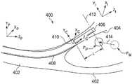
图4的示例示出了目标结构PM(例如,肿瘤、病变、结节)和附近的解剖通路402的虚拟图像400。通路402包括通路壁404。通路402位于具有坐标系(Xp、Yp、Zp)的患者参考系中。患者参考系可以是固定的参考系(即,在医疗程序中不会移动的参考系)。可以使用先前参考图1描述的方法将多个通路402的图像(例如,通过术前或术中建模获得)配准到患者参考系。目标结构PM的位置是在术前或术中成像中确定的,因此在患者参考系中是已知的。在本实施例中,解剖通路是肺部的支气管通路,但是本公开的系统和方法可以适用于在例如循环系统、消化系统、肾脏系统和生殖系统(包括诸如结肠、肠、肾、心脏等解剖系统)中的其他自然或手术创建的通路中使用。The example of FIG. 4 shows a
可以将柔性导管主体408(基本上类似于柔性主体216)导航到允许接近目标结构的导管停放位置。导管可以被定位在导管停放位置处,其取向允许导管的远端部分指向朝着目标结构的方向。以此方式,穿过柔性导管主体408插入的工具将沿着指向向量(pointing vector)插入到目标结构。可以使用例如视觉内窥镜、EM传感器和/或基于光纤形状的导航技术来对导管进行导航。成像探头406可以穿过柔性导管主体408插入。在一个实施例中,成像探头406是超声探头406。超声探头406可以使用超声换能器,例如侧面换能器、前向换能器、弯曲换能器、径向换能器等。在一个示例中,超声探头使用包括旋转超声换能器的侧成像换能器,以在基本垂直于换能器的旋转轴线的方向上成像。侧成像探头沿着成像平面412生成横截面(即径向)图像。可选地,超声探头406可以与导管成一整体,而不是如图4所示是可互换的。导管参考系和坐标系(Xc、Yc、Zc)被限定在导管408的远端部分410处,并且使用先前参考图1描述的方法与患者坐标系配准。在图4的实施例中,换能器的旋转轴线大致沿着导管参考系的Zc方向。Flexible catheter body 408 (substantially similar to flexible body 216) can be navigated to a catheter park location that allows access to the target structure. The catheter may be positioned at the catheter park position in an orientation that allows the distal portion of the catheter to point in the direction of the target structure. In this manner, a tool inserted through the
在一些实施例中,侧成像探头生成距旋转轴线的某一径向距离处的组织的图像,包括位于解剖通路之外的组织。在其他实施例中,可以使用前视超声探头来对换能器的远侧处的组织进行成像。超声探头可以相对较小以导航狭窄的解剖通路。例如,超声探头可以具有大约1.4mm的远端直径。In some embodiments, the side imaging probe generates images of tissue at some radial distance from the axis of rotation, including tissue located outside the anatomical pathway. In other embodiments, a forward looking ultrasound probe may be used to image tissue distal to the transducer. Ultrasound probes can be relatively small to navigate narrow anatomical pathways. For example, the ultrasound probe may have a distal diameter of approximately 1.4 mm.
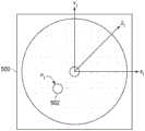
图5示出了由超声探头406在图4所示的成像平面412中生成的图像500。图像500具有图像参考系和坐标系(XI、YI、ZI)。目标结构502(PI)在图像参考系中被识别。例如,可以由临床医生、图像分析算法或两者的组合来识别。可以针对呼吸和/或心脏周期对超声扫描进行门控。尽管图像500是二维的,但是可以根据多个二维超声扫描来构造三维图像。与目标结构PI在图像参考系中的位置相关的数据被转换到导管坐标系或患者坐标系(已与导管坐标系配准)作为PP。可以将由超声探头确定的目标结构PP的位置与从术前或术中成像确定的目标结构PM在导管参考系或患者参考系中的位置进行比较,以确定校正向量414。校正向量414是目标结构PM的位置与目标结构PP的位置之间的偏移值。FIG. 5 shows an
在各种实施例中,为了将图像坐标系转换到导管坐标系,确定图像坐标系与导管坐标系之间的相对三维姿态。在一些实施例中,它由导管和成像探头上的传感器直接测量。此类传感器可以包括EM传感器、光纤形状传感器等。导管和成像探头上的传感器不需要是相同的类型。In various embodiments, to convert the image coordinate system to the catheter coordinate system, a relative three-dimensional pose between the image coordinate system and the catheter coordinate system is determined. In some embodiments, it is measured directly by sensors on the catheter and imaging probe. Such sensors may include EM sensors, fiber optic shape sensors, and the like. The sensors on the catheter and imaging probe do not need to be the same type.
在一些实施例中,假设成像探头笔直地伸出导管的尖端并且导管末端的姿态是已知的,则可以通过测量插入长度L和/或图像坐标系相对于导管坐标系的滚转角来计算图像坐标系(XI、YI、ZI)与导管坐标系(XC、YC、ZC)之间的相对姿态。在一些实施例中,基于目标相对于导管远端的相对位置的假设(例如,导管末端指向目标)来确定相对姿态。在这些实施例中,假设由导管递送的图像探头沿着导管的指向方向放置,因此,只需要确定与导管远端的距离。这样的距离可以是假定的距离,或者可以使用外部成像来确定。在一个示例中,在确定导管参考系中的目标位置和图像参考系中的目标位置(例如,来自捕获的超声图像)之后,可以确定图像参考系与导管参考系之间的转换。In some embodiments, the image may be calculated by measuring the insertion length L and/or the roll angle of the image coordinate system relative to the catheter coordinate system, assuming the imaging probe is straight out of the catheter tip and the pose of the catheter tip is known The relative pose between the coordinate system (XI , YI , ZI ) and the catheter coordinate system (XC , YC , ZC ). In some embodiments, the relative pose is determined based on an assumption of the relative position of the target with respect to the distal end of the catheter (eg, the catheter tip is pointing toward the target). In these embodiments, it is assumed that the image probe delivered by the catheter is placed along the direction in which the catheter is pointed, thus only the distance to the distal end of the catheter needs to be determined. Such distances may be assumed distances, or may be determined using external imaging. In one example, after determining the target position in the catheter reference frame and the target position in the image reference frame (eg, from a captured ultrasound image), a transformation between the image reference frame and the catheter reference frame can be determined.
在一些示例中,插入长度L可以使用例如编码器或步进马达来确定。可以使用多种技术来确定滚转角。例如,超声探头可以包括键合(keyed)在导管上的滚转对准特征件,其中滚转对准特征件使超声探头保持关于延伸穿过导管的导管滚转轴线(Zc)的固定取向。滚转对准特征件允许图像参考系和坐标系(XI、YI、ZI)的滚转角相对于导管参考系和坐标系(XC、YC、ZC)进行配准。在一些实施例中,滚转对准特征件是被键合以匹配导管中类似形状的通道的定形突出物。在替代实施例中,滚转对准特征件可以是形状与导管中的突出物相匹配的通道。可以使用多于一个滚转对准特征件来保持探头关于导管滚转轴线的固定取向。在另一可替代实施例中,可以由位于患者解剖体外部的滚转传感器来确定图像坐标系相对于导管坐标系的滚转角。在另一可替代实施例中,可以通过查看在由成像探头记录的图像中相对于导管具有已知角度的一个或多个标记或其他特征件来确定滚转角。例如,该特征件或标记可以位于导管的周界上,并且具有相当于导管的对比度(例如超声对比度)。在另一可替代实施例中,可以通过观察围绕导管的近端的探头上的图案或通过观察围绕探头的近端的导管上的图案来确定组合的滚转和插入长度。可以使用各种配准技术(例如光流)来配准图像坐标系和导管坐标系。In some examples, the insertion length L may be determined using, for example, an encoder or a stepper motor. A variety of techniques can be used to determine the roll angle. For example, the ultrasound probe may include a roll alignment feature keyed on the catheter, wherein the roll alignment feature maintains the ultrasound probe in a fixed orientation about the catheter roll axis (Zc) extending through the catheter. The roll alignment feature allows the roll angles of the image reference frame and coordinate system (XI , YI , ZI ) to be registered relative to the catheter reference frame and coordinate system (XC , YC , ZC ). In some embodiments, the roll alignment features are shaped protrusions that are keyed to match similarly shaped channels in the catheter. In alternative embodiments, the roll alignment feature may be a channel shaped to match a protrusion in the catheter. More than one roll alignment feature may be used to maintain a fixed orientation of the probe with respect to the catheter roll axis. In another alternative embodiment, the roll angle of the image coordinate system relative to the catheter coordinate system may be determined by a roll sensor located outside the patient's anatomy. In another alternative embodiment, the roll angle may be determined by looking at one or more markers or other features that have a known angle relative to the catheter in the image recorded by the imaging probe. For example, the feature or marker may be located on the perimeter of the catheter and have a contrast (eg, ultrasound contrast) equivalent to that of the catheter. In another alternative embodiment, the combined roll and insertion length can be determined by observing the pattern on the probe around the proximal end of the catheter or by observing the pattern on the catheter around the proximal end of the probe. Various registration techniques (eg, optical flow) can be used to register the image coordinate system and the catheter coordinate system.
参考图6,在一些实施例中,使用一个或多个外部图像来确定图像坐标系与导管坐标系之间的相对姿态,其中每个外部图像包括导管图像和成像探头图像。此类外部图像可以由计算机断层扫描(CT)、磁共振成像(MRI)、荧光透视法、热像仪、超声、光学相干断层扫描(OCT)、热成像、阻抗成像、激光成像、纳米管X射线成像和/或类似技术(例如,荧光镜)来提供。在图6的示例中,显示系统110显示来自外部荧光镜成像装置的患者解剖体的并发或实时外部图像602。外部图像602包括患者解剖体中的导管408、超声探头406和骨骼(例如肋骨604-1、604-2)的图像。在一些实施例中,操作者可以提供输入(例如,使用输入装置)以识别超声探头406和导管408的远端410的位置。在图6的示例中,显示系统110包括触摸屏,并且操作者可以使用触摸屏来识别外部图像602中的导管408的远端410(例如,通过使用标记“X”)和超声探头406(例如,通过使用标记“Δ”)。操作者可以通过选择按钮606将识别的位置提交给控制系统。6, in some embodiments, the relative pose between the image coordinate system and the catheter coordinate system is determined using one or more external images, wherein each external image includes a catheter image and an imaging probe image. Such external images can be obtained from computed tomography (CT), magnetic resonance imaging (MRI), fluoroscopy, thermal imaging, ultrasound, optical coherence tomography (OCT), thermal imaging, impedance imaging, laser imaging, nanotube X Radiographic and/or similar techniques (eg, fluoroscopy) are provided. In the example of FIG. 6,
在一些实施例中,控制系统可以通过使用图像分析算法来分析图像602以确定图像坐标系与导管坐标系之间的相对姿态,从而自动检测导管408的远端410和超声探头406在图像602中的位置。在一些示例中,图像602中已知的解剖标志尺度(例如,连续肋骨604-1与604-2之间的距离d1)可以用于确定导管408的远端410和超声探头406在图像602中的位置之间的距离d2。In some embodiments, the control system may automatically detect that the
在一些实施例中,使用两个或更多个外部图像来确定超声探头406和引导导管408的远端410的位置和/或相对位置。通过使用两个或更多个外部图像,可以基于超声探头406和导管408的远端410在每个外部图像上的位置从多个二维外部图像构建包括超声探头406和导管408的患者解剖体的三维图形。超声探头406和导管408的远端410在每个外部图像上的位置可以基于操作者输入或由控制系统执行的数字成像处理来识别。在一些实施例中,从不同观察方向由同一外部成像装置(例如,荧光镜成像装置)提供两个或更多个外部图像。在可替代实施例中,使用不同的成像技术(计算机断层扫描(CT)、磁共振成像(MRI)、荧光透视法、热像仪、超声、光学相干断层扫描(OCT)、热成像、阻抗成像、激光成像,或纳米管X射线成像等)向两个或更多个外部成像装置提供两个或更多个外部图形。In some embodiments, two or more external images are used to determine the position and/or relative position of the
参考图7、图8和图9,在一些实施例中,导管可以同时提供成像探头(例如,超声探头)和工具。在这些实施例中,来自成像探头的第一图像可以包括工具和目标结构两者,其可以用于确认或确定工具的尖端和目标结构的位置。在一些实施例中,可以基于不同于第一图像的来源(例如,患者解剖体的外部图像、导管的远端的已知姿态)来确定工具的尖端的附加位置数据,其可以用于确定目标结构的位置。通过使用来自成像探头的第一图像和工具的尖端的位置数据,可以在医疗过程(例如,活检、消融等)期间确定目标结构的位置。在一个示例中,可以在活检程序期间向操作者提供患者解剖体的虚拟可视化图像,其包括活检器械的图像和目标结构的图像,并提供将活检器械插入目标结构内的可视化效果。Referring to Figures 7, 8, and 9, in some embodiments, the catheter may provide both an imaging probe (eg, an ultrasound probe) and a tool. In these embodiments, the first image from the imaging probe may include both the tool and the target structure, which may be used to confirm or determine the position of the tool's tip and the target structure. In some embodiments, additional position data for the tip of the tool may be determined based on sources other than the first image (eg, external images of the patient's anatomy, known pose of the distal end of the catheter), which may be used to determine the target the location of the structure. Using the first image from the imaging probe and the position data of the tip of the tool, the position of the target structure can be determined during a medical procedure (eg, biopsy, ablation, etc.). In one example, the operator may be provided with a virtual visualization of the patient's anatomy, including an image of the biopsy instrument and an image of the target structure, and a visualization of the insertion of the biopsy instrument into the target structure, to the operator during the biopsy procedure.
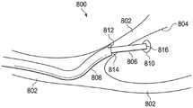
参考图7的示例,其示出了目标结构810和附近的解剖通路802的虚拟图像800。通路802包括通路壁804。如图7所示,在活检程序期间将活检器械806插入导管808的通道中。导管808可以被转向到提供接近目标结构810的位置和/或取向。可以通过导管的主动转向控制来直接完成导管的转向,或者通过导航可转向活检器械806来间接完成导管的转向。活检器械806从导管808延伸,穿过解剖通路802的壁804并与目标结构810接触,以允许获取组织样本,尽管在一些示例中,活检器械860的延伸可能被延迟,直到导管808的远端814被正确地定位。在可替代示例中,活检器械806可以由例如消融工具或解剖工具的治疗装置代替。Referring to the example of FIG. 7 , a
在图7的示例中,导管808包括位于导管808的远端814处的集成成像探头812(例如,超声探头)。在可替代实施例中,成像探头(例如,超声探头)可以同时穿过导管的第二通道被插入,而活检器械穿过导管的第一通道被插入。成像探头812位于通路802中,用于拍摄活检器械806和目标结构810的术中和实时图像。在各种实施例中,活检器械806和目标结构810的那些图像可以用于进一步帮助配准由成像探头812捕获的图像和/或相对于目标结构810、活检器械806和活检器械806的工具尖端816定位成像探头812。In the example of FIG. 7 ,
在图7的示例中,成像探头812是前向超声探头,其被用于捕获位于成像探头812的远侧的目标结构810和活检器械806(例如,当活检器械806穿透目标结构810时)的图像。在可替代实施例中,成像探头812包括侧成像探头812,该侧成像探头812通过沿侧成像探头812的成像平面(例如,图4中的成像探头406的成像平面412)生成横截面(即径向)图像来捕获目标结构810和活检器械806的图像。在各种实施例中,通过使用超声探头,可以捕获位于解剖通路之外的对象(例如,目标结构810、活检器械806的一部分)的图像。In the example of FIG. 7 ,
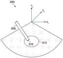
参考图8的示例,其示出了由图7所示的前向超声探头812生成的图像850。图像850具有图像参考系和坐标系(XI、YI、ZI),并且包括目标结构810的图像和包含其工具尖端816的活检器械806的图像。在各种实施例中,在图像参考系中识别目标结构810、活检器械806和工具尖端816。例如,可以由操作者(例如临床医生)、图像分析算法或两者的组合来识别。尽管图像850是二维的,但可以从多个二维超声图像构造三维图像。与图像参考系中的目标结构810和工具尖端816的位置相关联的数据被转换到导管坐标系或患者坐标系(已与导管坐标系配准)。目标结构810和工具尖端816在导管坐标系或患者坐标系中的位置数据可以用于在显示系统110上提供视觉虚拟化图像。Referring to the example of FIG. 8, an
在各种实施例中,除了基于由成像探头812提供的图像850确定的工具尖端816的第一位置数据之外,还可以使用基于来源(例如,导管808的远端814的已知姿态、来自外部成像装置的外部图像)的工具尖端816的第二位置数据来确定目标结构810的位置。在一些实施例中,基于导管808的远端814的已知姿态来确定工具尖端816的这种第二位置数据。例如,工具尖端816的第二位置数据可以指示工具尖端816沿着与导管808的远端814相同的方向。作为进一步的示例,工具尖端816的第二位置数据可以指示工具尖端816与导管808的远端814处于预定距离(例如,15mm)。In various embodiments, in addition to the first position data of the
参考图9,在一些实施例中,可以基于由外部成像装置提供的患者解剖体的外部图像来确定工具尖端816的第二位置数据。图9示出显示系统110显示来自外部荧光透视成像装置的患者解剖体的并发或实时外部图像902。外部图像902包括导管808、集成在导管808的远端814处的超声探头812、活检器械806以及活检器械806的工具尖端816的图像。Referring to Figure 9, in some embodiments, the second position data for the
在一些实施例中,操作者(例如,临床医生)可以提供输入(例如,使用输入装置)以识别外部图像902中的导管808的远端814和工具尖端816的位置。在图9的示例中,显示系统110包括触摸屏,并且操作者可以使用触摸屏来识别导管808的远端814的位置(例如,使用标记“X”),并且在外部图像902上识别工具尖端816的位置(例如,使用标记“Δ”)。然后,操作者可以将识别的位置提交给控制系统(例如,使用按钮906)。In some embodiments, an operator (eg, a clinician) may provide input (eg, using an input device) to identify the position of the
在一些实施例中,控制系统可以通过使用图像分析算法来识别外部图像902中的导管808的远端814和工具尖端816的位置。例如,图像分析算法可以用于在外部图像902中自动检测导管808的远端814和工具尖端816。在一些实例中,外部图像902中的已知的解剖标志尺度(例如,连续肋骨904-1与904-2之间的距离d3)可以用于确定导管808的远端814与工具尖端816之间的距离d4。In some embodiments, the control system may identify the position of the
参考图10的示例,其示出了根据一些实施例的用于使用成像探头来确定目标结构位置的方法1000。方法1000被示出为一组操作或过程1002至1014。并非所有示出的过程1002至1014都可以在方法1000的所有实施例中执行。另外,图10中未明确示出的一个或多个过程可以被包括在过程1002到1014之前、之后、之间或作为其一部分。在一些实施例中,一个或多个过程可以至少部分地以存储在非暂时的有形的机器可读介质上的可执行代码的形式实现,该可执行代码在由一个或多个处理器(例如,控制系统112的处理器)运行时可以促使一个或多个处理器执行一个或多个处理。Referring to the example of FIG. 10, a
方法1000开始于过程1002,其中从位于患者解剖体内部的成像探头(例如,超声探头)接收解剖结构的第一图像。在一些实施例中,如图4所示,成像探头406可以向远侧延伸超过导管408的远端410。在过程1002中,控制系统112从图4的成像探头406接收包括目标结构PI的解剖结构的图5的图像500。在可替代实施例中,如图7所示,成像探头812与导管808集成在一起并位于导管808的远端812处。在过程1002中,控制系统112接收包括目标结构810的解剖结构的图8的图像850,该图像由图7的成像探头806捕获。在其它可替代实施例中,成像探头可以同时穿过导管的第二通道插入,而器械(例如,活检器械)穿过导管的第一通道插入。
在过程1004中,控制系统112从位于患者解剖体之外的外部成像装置接收患者解剖体的一个或多个外部图像,其中这些外部图像包括导管、成像探头和/或器械的图像。在一些实施例中,如图6所示,控制系统112从位于患者解剖体之外的外部成像装置接收图6的一个或多个外部图像602。每个外部图像包括图4的导管408的图像和成像探头406的图像。在一些实施例中,如图9所示,控制系统112从位于患者解剖体之外的外部成像装置接收图9的一个或多个外部图像902。每个外部图像902包括导管808的图像、成像探头812的图像以及图8的工具806。In process 1004, the
方法1000随后可以进行到过程1010,其中确定与成像探头相关联的图像参考系和与导管的远端相关联的导管参考系之间的相对姿态。这样的相对姿态可以用于将图像参考系的第一图像中的目标结构和器械(例如,尖端)的位置数据转换到导管参考系。在一些实施例中,可以通过在导管和成像探头上的传感器直接测量相对姿态。此类传感器可以包括EM传感器、光纤形状传感器等。在可替代实施例中,可以通过使用两个或更多个外部图像(例如,由相对于患者解剖体具有不同观察方向的外部成像装置提供)来确定相对姿态。在这些实施例中,可以使用两个或更多个外部图像来确定成像探头和导管的三维位置,并且可以使用成像探头和导管的这些三维位置来确定相对姿态。
在一些实施例中,过程1010使用过程1006基于一个或多个外部图像来确定成像探头和导管的远端之间的相对位置,并且使用过程1008来确定成像探头和导管的远端之间的相对取向。在这些实施例中,过程1010使用在过程1006中确定的相对位置和在过程1008中确定的相对取向来确定相对姿态。In some embodiments,
在一些实施例中,在过程1006中,通过假设成像探头与导管的远端之间的恒定距离(例如,15mm)并通过假设成像探头沿着与导管的远端相同的方向,由此提供成像探头与导管的远端之间的相对位置。在另一可替代实施例中,如图6和图9所示,基于一个或多个外部图像(例如,使用操作者输入、图像分析算法和/或其组合)来确定成像探头与导管的远端之间的相对位置。例如,如图6所示,导管408的远端410和成像探头406在外部图像602中的位置可以通过操作者输入、图像分析算法和/或其组合来识别。In some embodiments, in
在过程1008中,确定成像探头与导管的远端之间的相对取向。在一些实施例中,在过程1008中,导管被导航到导管停放位置,在此处,导管的远端与解剖标志(例如,分叉)对齐。在这些实施例中,基于在来自成像探头的第一图像中检测到的相同解剖标志(例如,使用操作者输入、图像分析算法和/或其组合)来确定成像探头与导管的远端之间的相对取向。在可替代实施例中,成像探头被直接集成在导管中以保持固定取向。在一个示例中,成像探头可以嵌入在导管的远端。在另一示例中,成像探头可以包括键合(keyed)至导管的滚转对准特征件,以使成像探头保持关于延伸穿过导管的导管滚转轴线(Zc)的固定取向。在又一示例中,成像探头至少部分地被相对于导管可旋转地固定(例如,键控)的护套围绕。键控护套可以包括用于在第一图像中生成可识别区域的一个或多个标记(例如,发出回声的特征件),然后可以将其用作成像探头与导管的远端之间的参考滚转角。在其它可替代实施例中,可以使用位于患者解剖体之外的滚转传感器来确定成像探头与导管之间的滚转角。在另一实施例中,导管被引导以使得目标大致位于图像的中间。在该实施例中,导管被引导以使得目标沿着导管轴笔直向前,并且可能不需要成像探头与导管的远端之间的相对取向。In
在过程1012中,对于同时提供成像探头和工具的导管(例如,在活检期间),确定工具的尖端的第一位置数据和第二位置数据。如图8所示,使用由图7的成像探头812提供的图像850来确定工具尖端的第一位置数据。如图9所示,基于由外部成像装置提供的外部图像902(例如,使用操作者输入、图像分析算法和/或其组合)来确定工具尖端的第二位置数据。In process 1012, for a catheter that provides both an imaging probe and a tool (eg, during a biopsy), first position data and second position data for the tip of the tool are determined. As shown in FIG. 8, the
在过程1014中,可以基于目标结构在图像参考系中的位置数据、成像探头与导管的远端之间的相对姿态、第一工具尖端位置数据、第二工具尖端位置数据和/或其组合来确定目标结构在导管参考系和/或患者参考系中的位置数据。例如,可以基于相对姿态将目标结构在第一图像中的位置数据从图像参考系转换到导管参考系。作为进一步的示例,可以将目标结构在导管参考系中的位置数据转换到患者参考系。目标结构在导管参考系和/或患者参考系中的那些位置数据可以用于向操作者提供包括目标结构的患者解剖体的虚拟可视化图像。In process 1014, the target structure may be determined based on the position data of the target structure in the image reference frame, the relative pose between the imaging probe and the distal end of the catheter, the first tool tip position data, the second tool tip position data, and/or combinations thereof Position data of the target structure in the catheter reference frame and/or the patient reference frame is determined. For example, the positional data of the target structure in the first image can be transformed from the image reference frame to the catheter reference frame based on the relative pose. As a further example, the positional data of the target structure in the catheter reference frame may be converted to the patient reference frame. Those positional data of the target structure in the catheter reference frame and/or the patient reference frame can be used to provide the operator with a virtual visualization of the patient's anatomy including the target structure.
参考图11、图12A、图12B、图13和图14,可以使用目标结构在导管参考系和/或患者参考系中的位置数据向操作者提供各种视觉虚拟化图像。图11示出了用于使用基于来自成像探头的第一图像确定的目标结构的位置数据在显示系统上的虚拟可视化图像中呈现目标结构的方法1100。图12A-图12B示出了各种虚拟可视化图像,包括目标结构在患者解剖体的解剖模型中的虚拟表征。图13和图14示出了各种虚拟可视化图像,包括目标结构在患者解剖体的外部图像中的虚拟表征。11, 12A, 12B, 13, and 14, various visual virtualized images may be provided to the operator using positional data of the target structure in the catheter reference frame and/or the patient reference frame. 11 illustrates a
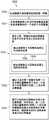
参考图11,其示出了一种方法1100,该方法使用基于来自成像探头的第一图像确定的目标结构的位置数据在显示系统上的虚拟可视化图像中呈现目标结构。方法1100被示出为一组操作或过程1102至1110。并非所有示出的过程1102至1110都可以在方法1100的所有实施例中执行。另外,图11中未明确示出的一个或多个过程可以被包括在过程1102至1110之前、之后、之间或作为其一部分。在一些实施例中,一个或多个过程可以至少部分地以存储在非暂时的有形的机器可读介质上的可执行代码的形式实现,该可执行代码在由一个或多个处理器(例如,控制系统112的处理器)运行时可以促使一个或多个处理器执行一个或多个处理。Referring to Figure 11, a
方法1100开始于过程1102,其中接收被转换到可视化参考系(例如,与解剖模型相关联的模型参考系或与外部图像相关联的患者参考系)的目标结构的位置数据。如方法1000中所描述,可以基于由成像探头提供的图像来确定可视化参考系中的目标结构的位置数据。The
在过程1104中,在一些实施例中,向操作者提供包括患者解剖体的解剖模型的图像和目标结构的图像的虚拟可视化图像。在这些实施例中,可视化参考系是模型参考系。参考图12A,在一些示例中,虚拟可视化图像包括解剖模型的全局视图。具体地,如图12A所示,在一些示例中,显示系统110将患者解剖体的虚拟可视化图像1202显示为包括通路的解剖模型1204。可以从使用如前所述的外部成像源收集的术前或术中图像来生成解剖模型1204。虚拟可视化图像1202还可以使用目标结构1214在模型参考系中的位置数据来提供目标结构1214的并发、更新或实时图像的视觉表征。在一些实施例中,目标结构1214的图像是使用由成像探头提供的多个图像生成的三维图像。通过基于由成像探头提供的一个或多个图像在虚拟可视化图像1202中投射具有正确位置和取向的目标结构1214的图像,虚拟可视化图像1202为操作者提供了对病变所在的目标结构的位置的改进的空间感知。另外,虚拟可视化图像1202可以包括解剖模型1204的通路1208中的导管1206以及从导管1206的远端1210延伸的工具1212的并发或实时虚拟图像。In
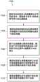
如图12B所示,在一些示例中,显示系统110显示患者解剖体的并发或实时虚拟可视化图像1250,该图像包括图12A的解剖模型1204的通路1208的内部视图。虚拟可视化图像1250提供导管1206和从导管1206的远端1210延伸的工具1212的虚拟图像。As shown in Figure 12B, in some examples,
在过程1106中,在一些实施例中,虚拟可视化图像包括患者解剖体的解剖模型上的图像,该图像包括基于由成像探头提供的图像确定的目标结构的更新目标位置。这种更新的目标位置可以进一步提供更好的瞄准方向,以实现对目标结构的最佳进入。In
在一些实施例中,在过程1106中,虚拟可视化图像包括基于由成像探头提供的图像来实现对目标结构的最佳进入的最佳导管停放位置的指示。在一些实施例中,当成像探头位于通路1208的多个不同位置处(例如,在允许捕获目标结构的图像的通路1208的区段的不同位置处)和/或处于不同的取向时,基于由成像探头捕获的多个顺序图像来确定最佳导管停放位置。对于那些顺序图像中的每一个,计算目标结构表面积测量值(例如,使用目标结构像素数量与图像的像素的总数量的比率)。在一些实施例中,目标结构表面积测量值可以将成像探头引导到使目标结构表面测量值最大化的最佳姿态。在一些实施例中,基于最佳成像探头姿态来确定最佳导管停放位置和/或最佳导管取向(例如,用于执行活检)。In some embodiments, in
在一些实施例中,可以使用自动优化来生成基于目标结构表面积测量值确定的导管驱动路径。导管驱动路径可以允许导管沿着目标结构表面积测量值的梯度驱动,以实现最佳目标结构表面测量值。在一些示例中,最佳导管停放位置和最佳导管取位可以用于驱动导管的尖端在某个区域内的自动扫描。In some embodiments, automatic optimization can be used to generate a catheter drive path determined based on target structure surface area measurements. The catheter drive path may allow the catheter to be driven along a gradient of target structure surface area measurements to achieve optimal target structure surface measurements. In some examples, the optimal catheter parking position and optimal catheter positioning may be used to drive automated scanning of the catheter tip within a certain area.
在过程1108中,向操作者提供包括来自患者解剖体之外的外部成像装置的外部图像和目标结构的图像的虚拟可视化图像。利用目标结构在患者参考系中的位置数据在虚拟可视化图像中提供目标结构的图像。例如,如图13所示,显示系统110包括虚拟可视化图像1300,该图像包括活检期间的实时外部图像1302。该实时外部图像1302包括导管808、集成到导管808的远端814的成像探头812、工具806和工具尖端816的图像。使用由成像探头在患者参考系中提供的目标结构的位置数据在虚拟可视化图像中提供目标结构1304的图像。在图13的示例中,通过使用捕获目标结构1304和工具尖端816的图像的成像探头来实现在活检期间将工具尖端816插入目标结构1304中的虚拟可视化。In
在过程1110中,向操作者提供虚拟可视化图像,该虚拟可视化图像包括来自患者解剖体之外的外部成像装置的外部图像和基于成像探头的位置数据的参考导管图像。在图14的示例中,显示系统110包括虚拟可视化图像1402。虚拟可视化图像1402包括活检期间的实时外部图像1404,该实时外部图像1404包括用于导管1406的实时图像。在过程1110中,从导管的通道移除成像探头,并将工具1410(例如,活检针)插入该通道中。在图14的示例中,基于目标结构在患者参考系中的位置数据在外部图像1404中提供目标结构1408的图像。此外,当成像探头被驱动以捕获目标结构的图像时,基于先前收集的成像探头和导管的位置数据,在外部图像1404中提供导管1412的参考图像。In
本公开的系统和方法可以用于连接的肺部支气管通路。该系统和方法也可以适用于在包括结肠、肠、肾、脑、心脏、循环系统等的各种解剖系统中的任何一种中经由自然或手术创建的连接通路来导航和治疗其它组织。该系统和方法也可以适用于在器官的可追踪表面周围进行导航。本公开的方法和实施例也适用于非手术应用。The systems and methods of the present disclosure may be used for connected pulmonary bronchial access. The systems and methods may also be adapted to navigate and treat other tissues via naturally or surgically created connecting pathways in any of a variety of anatomical systems including colon, intestine, kidney, brain, heart, circulatory system, and the like. The system and method may also be adapted for navigating around trackable surfaces of organs. The methods and embodiments of the present disclosure are also suitable for non-surgical applications.
本发明的实施例中的一个或多个元件可以用软件实现以在计算机系统(例如控制系统112)的处理器上执行。当以软件实现时,本发明的实施例的元件基本上是执行必要任务的代码段。程序或代码段可以被存储在处理器可读存储介质或装置中,其可能已经通过在传输介质或通信链路上以载波形式体现的计算机数据信号的形式来下载。处理器可读存储介质可以包括能够存储信息的任何介质,包括光学介质、半导体介质和磁介质。处理器可读存储介质示例包括:电子电路;半导体器件,半导体存储器器件、只读存储器(ROM)、闪速存储器、可擦除可编程只读存储器(EPROM);软盘、CD-ROM、光盘、硬盘或其他存储装置。代码段可以通过诸如因特网、内联网等计算机网络来下载。One or more elements of an embodiment of the invention may be implemented in software to execute on a processor of a computer system (eg, control system 112). When implemented in software, the elements of an embodiment of the invention are essentially code segments that perform the necessary tasks. The program or code segments may be stored in a processor-readable storage medium or device, which may have been downloaded in the form of a computer data signal embodied in the form of a carrier wave over a transmission medium or communication link. Processor-readable storage media may include any media capable of storing information, including optical media, semiconductor media, and magnetic media. Examples of processor-readable storage media include: electronic circuits; semiconductor devices, semiconductor memory devices, read only memory (ROM), flash memory, erasable programmable read only memory (EPROM); floppy disks, CD-ROMs, optical disks, hard disk or other storage device. Code segments may be downloaded over a computer network such as the Internet, an intranet, or the like.
应注意,所呈现的过程和显示器可能不固有地与任何特定计算机或其他设备相关。各种通用系统可以与根据本文的教导的程序一起使用,或者可以证明能够方便地构造更专用的设备来执行所描述的操作。各种此类系统所需的结构将作为权利要求中的元件出现。另外,不参考任何特定编程语言来描述本发明的实施例。应当理解,可以使用各种编程语言来实现如本文所述的本发明的教导。It should be noted that the processes and displays presented may not be inherently related to any particular computer or other device. Various general-purpose systems may be used with programs in accordance with the teachings herein, or it may prove convenient to construct more specialized apparatus to perform the described operations. The required structure for a variety of such systems will appear as elements in the claims. Additionally, embodiments of the present invention are not described with reference to any particular programming language. It should be understood that various programming languages may be used to implement the teachings of the present invention as described herein.
虽然已经在附图中描述和示出了本发明的某些示例性实施例,但是应该理解,这些实施例仅仅是对宽泛发明的说明而非限制,并且本发明的实施例不限于所示和所述的具体构造和布置,因为本领域普通技术人员可以想到各种其他修改。While certain exemplary embodiments of the invention have been described and illustrated in the accompanying drawings, it is to be understood that these embodiments are merely illustrative of the broad invention and not limiting and that the embodiments of the invention are not limited to those shown and The specific constructions and arrangements are described, as various other modifications will occur to those of ordinary skill in the art.
Claims (34)
Applications Claiming Priority (3)
| Application Number | Priority Date | Filing Date | Title |
|---|---|---|---|
| US201862662440P | 2018-04-25 | 2018-04-25 | |
| US62/662,440 | 2018-04-25 | ||
| PCT/US2019/028617WO2019209767A1 (en) | 2018-04-25 | 2019-04-23 | Systems and methods related to elongate devices |
Publications (2)
| Publication Number | Publication Date |
|---|---|
| CN112004496Atrue CN112004496A (en) | 2020-11-27 |
| CN112004496B CN112004496B (en) | 2024-10-18 |
Family
ID=66677209
Family Applications (1)
| Application Number | Title | Priority Date | Filing Date |
|---|---|---|---|
| CN201980027428.6AActiveCN112004496B (en) | 2018-04-25 | 2019-04-23 | Systems and methods relating to elongate devices |
Country Status (6)
| Country | Link |
|---|---|
| US (1) | US20210100627A1 (en) |
| EP (1) | EP3784161A1 (en) |
| JP (2) | JP2021521959A (en) |
| KR (1) | KR102843196B1 (en) |
| CN (1) | CN112004496B (en) |
| WO (1) | WO2019209767A1 (en) |
Cited By (7)
| Publication number | Priority date | Publication date | Assignee | Title |
|---|---|---|---|---|
| CN112741692A (en)* | 2020-12-18 | 2021-05-04 | 上海卓昕医疗科技有限公司 | Rapid navigation method and system for realizing device navigation to target tissue position |
| CN113017702A (en)* | 2021-03-05 | 2021-06-25 | 深圳英美达医疗技术有限公司 | Method and system for identifying extension length of small probe of ultrasonic endoscope and storage medium |
| CN114376625A (en)* | 2022-01-14 | 2022-04-22 | 上海立升医疗科技有限公司 | Biopsy data visualization system and biopsy device |
| CN114452508A (en)* | 2021-10-20 | 2022-05-10 | 上海微创微航机器人有限公司 | Catheter motion control method, interventional operation system, electronic device, and storage medium |
| CN115444573A (en)* | 2022-08-10 | 2022-12-09 | 上海优医基医学科技有限公司 | Flexible instrument control method, system and surgical robot |
| CN116570375A (en)* | 2023-06-27 | 2023-08-11 | 上海博动医疗科技股份有限公司 | Control method and device of interventional operation system, interventional operation system and medium |
| WO2024114021A1 (en)* | 2022-11-29 | 2024-06-06 | 深圳心寰科技有限公司 | 4d intracardiac echocardiography imaging system, echocardiography imaging method and echocardiography imaging apparatus |
Families Citing this family (26)
| Publication number | Priority date | Publication date | Assignee | Title |
|---|---|---|---|---|
| EP3328308B1 (en)* | 2016-09-27 | 2019-05-29 | Brainlab AG | Efficient positioning of a mechatronic arm |
| CN112826497B (en) | 2019-11-25 | 2025-09-09 | 巴德阿克塞斯系统股份有限公司 | Optical tip tracking system and method thereof |
| US20210169583A1 (en)* | 2019-12-04 | 2021-06-10 | Covidien Lp | Method for maintaining localization of distal catheter tip to target during ventilation and/or cardiac cycles |
| CN113842536A (en) | 2020-06-26 | 2021-12-28 | 巴德阿克塞斯系统股份有限公司 | Dislocation detection system |
| US20210401399A1 (en)* | 2020-06-26 | 2021-12-30 | Xenter, Inc. | Nanoparticle-based imaging and therapy |
| WO2022005870A1 (en)* | 2020-06-29 | 2022-01-06 | Bard Access Systems, Inc. | Automatic dimensional frame reference for fiber optic |
| KR102423825B1 (en)* | 2020-07-14 | 2022-07-22 | 서울대학교병원 | Processing Method for Tailored Laser Ablation System and Automatic Laser Ablation Device using it |
| US11844567B2 (en)* | 2020-08-28 | 2023-12-19 | Biosense Webster (Israel) Ltd. | Fitting and directing an expandable catheter based on automatic pulmonary veins anatomical characterization |
| DE102020212086A1 (en)* | 2020-09-25 | 2022-03-31 | Siemens Healthcare Gmbh | Determining the quality of a positioning of an object introduced into a patient's body |
| US12426954B2 (en) | 2021-01-26 | 2025-09-30 | Bard Access Systems, Inc. | Fiber optic shape sensing system associated with port placement |
| US20240153113A1 (en)* | 2021-03-10 | 2024-05-09 | Intuitive Surgical Operations, Inc. | Systems and methods for registering intraoperative image data |
| WO2022237787A1 (en)* | 2021-05-10 | 2022-11-17 | 武汉联影智融医疗科技有限公司 | Robot positioning and pose adjustment method and system |
| US11857273B2 (en)* | 2021-07-06 | 2024-01-02 | Globus Medical, Inc. | Ultrasonic robotic surgical navigation |
| US12419694B2 (en) | 2021-10-25 | 2025-09-23 | Bard Access Systems, Inc. | Reference plane for medical device placement |
| EP4292510A1 (en) | 2022-06-16 | 2023-12-20 | Lys Medical SA | Navigation catheter assembly with endoscopic vision probe |
| EP4298984A3 (en) | 2022-06-27 | 2024-02-28 | Cook Medical Technologies LLC | Endoscope lighting control with camera extension |
| US12343117B2 (en) | 2022-06-28 | 2025-07-01 | Bard Access Systems, Inc. | Fiber optic medical systems and methods for identifying blood vessels |
| US12349984B2 (en) | 2022-06-29 | 2025-07-08 | Bard Access Systems, Inc. | System, method, and apparatus for improved confirm of an anatomical position of a medical instrument |
| EP4437992A1 (en)* | 2023-03-30 | 2024-10-02 | Koninklijke Philips N.V. | Elongated device tracking |
| WO2024126639A1 (en)* | 2022-12-16 | 2024-06-20 | Koninklijke Philips N.V. | Elongated device tracking |
| US12127804B1 (en) | 2023-04-29 | 2024-10-29 | Syncrobotix, Inc. | Simplified highly maneuverable surgical catheter and bronchoscope |
| US12127737B1 (en)* | 2023-04-29 | 2024-10-29 | Syncrobotix, Inc. | System and method for operating a highly maneuverable surgical catheter and bronchoscope |
| US12433693B2 (en) | 2023-04-29 | 2025-10-07 | Syncrobotix, Inc. | Rotary and linear actuated robotic catheter steering system |
| US12127805B1 (en) | 2023-04-29 | 2024-10-29 | Syncrobotix, Inc. | Highly maneuverable surgical catheter and drive system |
| US11950765B1 (en) | 2023-04-29 | 2024-04-09 | Syncrobotix, Inc. | Highly maneuverable surgical catheter and bronchoscope |
| CN119214691A (en)* | 2024-12-05 | 2024-12-31 | 上海冰座晶依科技有限公司 | Control method, control device and electronic equipment for intracardiac ultrasonic catheter |
Citations (8)
| Publication number | Priority date | Publication date | Assignee | Title |
|---|---|---|---|---|
| US5307816A (en)* | 1991-08-21 | 1994-05-03 | Kabushiki Kaisha Toshiba | Thrombus resolving treatment apparatus |
| US20100256558A1 (en)* | 2008-03-27 | 2010-10-07 | Olson Eric S | Robotic catheter system |
| CN103619278A (en)* | 2011-06-17 | 2014-03-05 | 皇家飞利浦有限公司 | System and method for guided injection during endoscopic surgery |
| CN103648361A (en)* | 2011-05-13 | 2014-03-19 | 直观外科手术操作公司 | Medical system providing dynamic registration of a model of an anatomical structure for image-guided surgery |
| WO2014106249A1 (en)* | 2012-12-31 | 2014-07-03 | Intuitive Surgical Operations, Inc. | Systems and methods for interventional procedure planning |
| US20150305612A1 (en)* | 2014-04-23 | 2015-10-29 | Mark Hunter | Apparatuses and methods for registering a real-time image feed from an imaging device to a steerable catheter |
| CN105208960A (en)* | 2013-05-16 | 2015-12-30 | 直观外科手术操作公司 | Systems and methods for robotic medical systems integrated with external imaging |
| US20180064415A1 (en)* | 2016-09-07 | 2018-03-08 | Siemens Medical Solutions Usa, Inc. | Acoustic ablation assisted intra-cardiac echocardiography catheter |
Family Cites Families (17)
| Publication number | Priority date | Publication date | Assignee | Title |
|---|---|---|---|---|
| FR2567149B1 (en) | 1984-07-06 | 1986-12-05 | Solvay | PROCESS FOR THE EXTRACTION OF POLY-BETA-HYDROXYBUTYRATES USING A SOLVENT FROM AN AQUEOUS SUSPENSION OF MICROORGANISMS |
| US5740808A (en)* | 1996-10-28 | 1998-04-21 | Ep Technologies, Inc | Systems and methods for guilding diagnostic or therapeutic devices in interior tissue regions |
| US5797849A (en)* | 1995-03-28 | 1998-08-25 | Sonometrics Corporation | Method for carrying out a medical procedure using a three-dimensional tracking and imaging system |
| US5792135A (en) | 1996-05-20 | 1998-08-11 | Intuitive Surgical, Inc. | Articulated surgical instrument for performing minimally invasive surgery with enhanced dexterity and sensitivity |
| WO1998036236A1 (en) | 1997-02-13 | 1998-08-20 | Super Dimension Ltd. | Six-degree tracking system |
| ES2247685T3 (en)* | 1997-02-25 | 2006-03-01 | Biosense Webster, Inc. | TORAX THERAPY EQUIPMENT GUIDED BY IMAGE. |
| GB9713018D0 (en) | 1997-06-20 | 1997-08-27 | Secr Defence | Optical fibre bend sensor |
| JP4095729B2 (en)* | 1998-10-26 | 2008-06-04 | 株式会社日立製作所 | Therapeutic ultrasound system |
| US20040034297A1 (en)* | 2002-08-13 | 2004-02-19 | General Electric Company | Medical device positioning system and method |
| US8364242B2 (en)* | 2007-05-17 | 2013-01-29 | General Electric Company | System and method of combining ultrasound image acquisition with fluoroscopic image acquisition |
| JP2009297346A (en)* | 2008-06-16 | 2009-12-24 | Fujifilm Corp | Ultrasonic observation apparatus, ultrasonic endoscopic apparatus, image processing method, and image processing program |
| US8460236B2 (en)* | 2010-06-24 | 2013-06-11 | Hansen Medical, Inc. | Fiber optic instrument sensing system |
| US10588595B2 (en)* | 2011-07-01 | 2020-03-17 | Koninklijke Philips N.V. | Object-pose-based initialization of an ultrasound beamformer |
| US10758198B2 (en)* | 2014-02-25 | 2020-09-01 | DePuy Synthes Products, Inc. | Systems and methods for intra-operative image analysis |
| CN107660134B (en) | 2015-05-22 | 2021-06-29 | 直观外科手术操作公司 | System and method for image-guided surgical recording |
| EP3413830B1 (en)* | 2016-02-12 | 2022-06-15 | Intuitive Surgical Operations, Inc. | Computer program for using registered fluoroscopic images in image-guided surgery |
| US9675319B1 (en)* | 2016-02-17 | 2017-06-13 | Inneroptic Technology, Inc. | Loupe display |
- 2019
- 2019-04-23WOPCT/US2019/028617patent/WO2019209767A1/ennot_activeCeased
- 2019-04-23CNCN201980027428.6Apatent/CN112004496B/enactiveActive
- 2019-04-23EPEP19727765.0Apatent/EP3784161A1/enactivePending
- 2019-04-23JPJP2020558890Apatent/JP2021521959A/enactivePending
- 2019-04-23USUS17/044,354patent/US20210100627A1/enactivePending
- 2019-04-23KRKR1020207033475Apatent/KR102843196B1/enactiveActive
- 2023
- 2023-08-04JPJP2023127865Apatent/JP2023133606A/enactivePending
Patent Citations (10)
| Publication number | Priority date | Publication date | Assignee | Title |
|---|---|---|---|---|
| US5307816A (en)* | 1991-08-21 | 1994-05-03 | Kabushiki Kaisha Toshiba | Thrombus resolving treatment apparatus |
| US20100256558A1 (en)* | 2008-03-27 | 2010-10-07 | Olson Eric S | Robotic catheter system |
| CN103648361A (en)* | 2011-05-13 | 2014-03-19 | 直观外科手术操作公司 | Medical system providing dynamic registration of a model of an anatomical structure for image-guided surgery |
| CN105919547A (en)* | 2011-05-13 | 2016-09-07 | 直观外科手术操作公司 | Medical system providing dynamic registration of a model of an anatomical structure of operating for image-guided surgery |
| CN103619278A (en)* | 2011-06-17 | 2014-03-05 | 皇家飞利浦有限公司 | System and method for guided injection during endoscopic surgery |
| WO2014106249A1 (en)* | 2012-12-31 | 2014-07-03 | Intuitive Surgical Operations, Inc. | Systems and methods for interventional procedure planning |
| US20140187949A1 (en)* | 2012-12-31 | 2014-07-03 | Intuitive Surgical Operations, Inc. | Systems and Methods For Interventional Procedure Planning |
| CN105208960A (en)* | 2013-05-16 | 2015-12-30 | 直观外科手术操作公司 | Systems and methods for robotic medical systems integrated with external imaging |
| US20150305612A1 (en)* | 2014-04-23 | 2015-10-29 | Mark Hunter | Apparatuses and methods for registering a real-time image feed from an imaging device to a steerable catheter |
| US20180064415A1 (en)* | 2016-09-07 | 2018-03-08 | Siemens Medical Solutions Usa, Inc. | Acoustic ablation assisted intra-cardiac echocardiography catheter |
Cited By (10)
| Publication number | Priority date | Publication date | Assignee | Title |
|---|---|---|---|---|
| CN112741692A (en)* | 2020-12-18 | 2021-05-04 | 上海卓昕医疗科技有限公司 | Rapid navigation method and system for realizing device navigation to target tissue position |
| CN112741692B (en)* | 2020-12-18 | 2021-12-14 | 上海卓昕医疗科技有限公司 | Rapid navigation method and system for realizing device navigation to target tissue position |
| CN113017702A (en)* | 2021-03-05 | 2021-06-25 | 深圳英美达医疗技术有限公司 | Method and system for identifying extension length of small probe of ultrasonic endoscope and storage medium |
| WO2022184154A1 (en)* | 2021-03-05 | 2022-09-09 | 深圳英美达医疗技术有限公司 | Method and system for recognizing extension length of miniature endoscopic ultrasonography probe, and storage medium |
| CN114452508A (en)* | 2021-10-20 | 2022-05-10 | 上海微创微航机器人有限公司 | Catheter motion control method, interventional operation system, electronic device, and storage medium |
| CN114452508B (en)* | 2021-10-20 | 2024-01-23 | 上海微创微航机器人有限公司 | Catheter motion control method, interventional operation system, electronic device, and storage medium |
| CN114376625A (en)* | 2022-01-14 | 2022-04-22 | 上海立升医疗科技有限公司 | Biopsy data visualization system and biopsy device |
| CN115444573A (en)* | 2022-08-10 | 2022-12-09 | 上海优医基医学科技有限公司 | Flexible instrument control method, system and surgical robot |
| WO2024114021A1 (en)* | 2022-11-29 | 2024-06-06 | 深圳心寰科技有限公司 | 4d intracardiac echocardiography imaging system, echocardiography imaging method and echocardiography imaging apparatus |
| CN116570375A (en)* | 2023-06-27 | 2023-08-11 | 上海博动医疗科技股份有限公司 | Control method and device of interventional operation system, interventional operation system and medium |
Also Published As
| Publication number | Publication date |
|---|---|
| JP2023133606A (en) | 2023-09-22 |
| CN112004496B (en) | 2024-10-18 |
| US20210100627A1 (en) | 2021-04-08 |
| KR20210005901A (en) | 2021-01-15 |
| KR102843196B1 (en) | 2025-08-08 |
| EP3784161A1 (en) | 2021-03-03 |
| JP2021521959A (en) | 2021-08-30 |
| WO2019209767A1 (en) | 2019-10-31 |
Similar Documents
| Publication | Publication Date | Title |
|---|---|---|
| CN112004496B (en) | Systems and methods relating to elongate devices | |
| US11871898B2 (en) | Systems and methods for interventional procedure planning | |
| US12343094B2 (en) | Systems and methods for using tracking in image-guided medical procedure | |
| US12369980B2 (en) | Systems and methods for intelligently seeding registration | |
| US20240041531A1 (en) | Systems and methods for registering elongate devices to three-dimensional images in image-guided procedures | |
| CN110225710B (en) | System and method for registration of image-guided procedures | |
| CN107690302B (en) | System and method for registration compensation in image-guided surgery | |
| JP2018515253A (en) | Registration system and method for image guided surgery | |
| US20210259783A1 (en) | Systems and Methods Related to Registration for Image Guided Surgery | |
| CN113710145A (en) | System for enhanced registration of patient anatomy | |
| US20220054202A1 (en) | Systems and methods for registration of patient anatomy |
Legal Events
| Date | Code | Title | Description |
|---|---|---|---|
| PB01 | Publication | ||
| PB01 | Publication | ||
| SE01 | Entry into force of request for substantive examination | ||
| SE01 | Entry into force of request for substantive examination | ||
| GR01 | Patent grant | ||
| GR01 | Patent grant |