CN112003485A - Current continuous control method based on bridgeless SEPIC-PFC circuit - Google Patents
Current continuous control method based on bridgeless SEPIC-PFC circuitDownload PDFInfo
- Publication number
- CN112003485A CN112003485ACN202010930238.XACN202010930238ACN112003485ACN 112003485 ACN112003485 ACN 112003485ACN 202010930238 ACN202010930238 ACN 202010930238ACN 112003485 ACN112003485 ACN 112003485A
- Authority
- CN
- China
- Prior art keywords
- integrator
- circuit
- output voltage
- current
- duty cycle
- Prior art date
- Legal status (The legal status is an assumption and is not a legal conclusion. Google has not performed a legal analysis and makes no representation as to the accuracy of the status listed.)
- Granted
Links
Images


Classifications
- H—ELECTRICITY
- H02—GENERATION; CONVERSION OR DISTRIBUTION OF ELECTRIC POWER
- H02M—APPARATUS FOR CONVERSION BETWEEN AC AND AC, BETWEEN AC AND DC, OR BETWEEN DC AND DC, AND FOR USE WITH MAINS OR SIMILAR POWER SUPPLY SYSTEMS; CONVERSION OF DC OR AC INPUT POWER INTO SURGE OUTPUT POWER; CONTROL OR REGULATION THEREOF
- H02M7/00—Conversion of AC power input into DC power output; Conversion of DC power input into AC power output
- H02M7/02—Conversion of AC power input into DC power output without possibility of reversal
- H02M7/04—Conversion of AC power input into DC power output without possibility of reversal by static converters
- H02M7/12—Conversion of AC power input into DC power output without possibility of reversal by static converters using discharge tubes with control electrode or semiconductor devices with control electrode
- H02M7/21—Conversion of AC power input into DC power output without possibility of reversal by static converters using discharge tubes with control electrode or semiconductor devices with control electrode using devices of a triode or transistor type requiring continuous application of a control signal
- H02M7/217—Conversion of AC power input into DC power output without possibility of reversal by static converters using discharge tubes with control electrode or semiconductor devices with control electrode using devices of a triode or transistor type requiring continuous application of a control signal using semiconductor devices only
- H—ELECTRICITY
- H02—GENERATION; CONVERSION OR DISTRIBUTION OF ELECTRIC POWER
- H02M—APPARATUS FOR CONVERSION BETWEEN AC AND AC, BETWEEN AC AND DC, OR BETWEEN DC AND DC, AND FOR USE WITH MAINS OR SIMILAR POWER SUPPLY SYSTEMS; CONVERSION OF DC OR AC INPUT POWER INTO SURGE OUTPUT POWER; CONTROL OR REGULATION THEREOF
- H02M1/00—Details of apparatus for conversion
- H02M1/42—Circuits or arrangements for compensating for or adjusting power factor in converters or inverters
- H02M1/4208—Arrangements for improving power factor of AC input
- Y—GENERAL TAGGING OF NEW TECHNOLOGICAL DEVELOPMENTS; GENERAL TAGGING OF CROSS-SECTIONAL TECHNOLOGIES SPANNING OVER SEVERAL SECTIONS OF THE IPC; TECHNICAL SUBJECTS COVERED BY FORMER USPC CROSS-REFERENCE ART COLLECTIONS [XRACs] AND DIGESTS
- Y02—TECHNOLOGIES OR APPLICATIONS FOR MITIGATION OR ADAPTATION AGAINST CLIMATE CHANGE
- Y02B—CLIMATE CHANGE MITIGATION TECHNOLOGIES RELATED TO BUILDINGS, e.g. HOUSING, HOUSE APPLIANCES OR RELATED END-USER APPLICATIONS
- Y02B70/00—Technologies for an efficient end-user side electric power management and consumption
- Y02B70/10—Technologies improving the efficiency by using switched-mode power supplies [SMPS], i.e. efficient power electronics conversion e.g. power factor correction or reduction of losses in power supplies or efficient standby modes
Landscapes
- Engineering & Computer Science (AREA)
- Power Engineering (AREA)
- Rectifiers (AREA)
Abstract
Translated fromChinese
Description
Translated fromChinese技术领域technical field
本发明涉及电路控制领域,尤其是一基于无桥SEPIC-PFC电路的电流连续控制方法。The invention relates to the field of circuit control, in particular to a current continuous control method based on a bridgeless SEPIC-PFC circuit.
背景技术Background technique
由于开关电源具有体积小、功率密度大和工作效率高的一系列优点,因此得到了越来越广泛的应用。但是作为AC/DC变换的高频开关电源或一些交流市电的非线性负载,由于会使交流输入市电的正弦输入电流波形发生畸变,产生了大量的谐波电流成分,直接影响到电网供电质量和用户使用的安全性,尤其是传统的用于电子设备前端的单相二极管整流桥。近年来,国内外学者提出了许多基于SEPIC电路的带隔离变压器无桥式PFC电路,但基本都是以交流侧电流断续状态工作,导致功率开关器件的电流应力增大,电磁干扰严重。Due to the advantages of small size, high power density and high working efficiency, switching power supplies have been widely used. However, as a high-frequency switching power supply of AC/DC conversion or some nonlinear loads of AC mains, since the sinusoidal input current waveform of AC input mains will be distorted, a large amount of harmonic current components will be generated, which will directly affect the power supply of the grid. Quality and user safety, especially for traditional single-phase diode rectifier bridges used in the front end of electronic equipment. In recent years, scholars at home and abroad have proposed many bridgeless PFC circuits with isolation transformers based on SEPIC circuits, but they basically work in the state of intermittent current on the AC side, resulting in increased current stress of power switching devices and serious electromagnetic interference.
单周期控制技术(one-cycle control,OCC)是20世纪90年代美国加州大学的Keyue M Smedley提出的,它是一种不需要乘法器的新颖控制方法。单周期控制的理念是基于实时控制开关的占空比,使每个周期内被控量波形的平均值恰好等于或者正比于控制参考量,平均输入电流跟踪参考电流且不受负载电流的约束,即使负载电流具有很大的谐波也不会使输入电流发生畸变。One-cycle control (OCC) was proposed by Keyue M Smedley of the University of California in the 1990s. It is a novel control method that does not require multipliers. The concept of single-cycle control is based on real-time control of the duty cycle of the switch, so that the average value of the waveform of the controlled variable in each cycle is exactly equal to or proportional to the control reference value, and the average input current tracks the reference current and is not constrained by the load current. Even if the load current has large harmonics, the input current will not be distorted.
近年来,单周期控制技术广泛应用于BOOST-PFC电路中,如专利号为CN104638900A的“一种应用于无桥式SEPIC-PFC电路的单周期控制方法”中是断续电流的控制技术,而在电流连续型带隔离的无桥SEPIC-PFC的应用中未见报道,因此研究单周期控制技术在电流连续型带隔离的无桥SEPIC-PFC中的应用有重要意义。In recent years, single-cycle control technology has been widely used in BOOST-PFC circuits. For example, the "Single-cycle control method applied to bridgeless SEPIC-PFC circuit" with the patent number of CN104638900A is the control technology of discontinuous current. There is no report on the application of the current continuous type bridgeless SEPIC-PFC with isolation, so it is of great significance to study the application of single-cycle control technology in the current continuous type bridgeless SEPIC-PFC with isolation.
发明内容SUMMARY OF THE INVENTION
本发明是提供一基于无桥SEPIC-PFC电路的电流连续控制方法,将单周期控制技术应用到电流连续型带隔离的无桥SEPIC-PFC电路中,以获得交流侧电流连续以及更高的功率因数,适用于大功率PFC应用场合。The invention provides a current continuous control method based on a bridgeless SEPIC-PFC circuit, and applies the single-cycle control technology to the current continuous bridgeless SEPIC-PFC circuit with isolation to obtain continuous current on the AC side and higher power. factor, suitable for high power PFC applications.
为解决上述技术问题,本发明所采用的技术方案是:For solving the above-mentioned technical problems, the technical scheme adopted in the present invention is:
一种基于无桥SEPIC-PFC电路的电流连续控制方法,步骤如下:A current continuous control method based on a bridgeless SEPIC-PFC circuit, the steps are as follows:
S1:计算无桥SEPIC-PFC电路主电路的静态电压增益S1: Calculate the static voltage gain of the main circuit of the bridgeless SEPIC-PFC circuit


S2:求占空比表达式S2: Find the duty cycle expression
校正功率因数,

令

(iL×Rs+n×Um)×D=n×Um(6)(iL ×Rs +n×Um )×D=n×Um (6)
其中,Ui为输入电压,Uo为输出电压,n为变压器初级与次级匝数比,D为一个开关周期内的占空比,iL为输入电流,Re为等效输入电阻,Rs为采样电阻;S3:搭建电路,构建占空比D的表达式,检测主电路的输入电流iL,输出电压Uo,构造占空比D,构造中使用一个积分器,根据单周期控制在CCM(continuous conduction mode)电路中的原理,积分器的输出应为
S4:利用步骤S3中检测的主电路的输入电流iL,输出电压Uo通过加法器、积分器实现占空比D的表达,输出电压误差经过PI调节器、复位积分器后得到(iL×Rs+n×Um)×D,将其与n×Um的值通过比较器,再经过RS触发器,输出的是PWM脉冲序列;用以控制主电路中开关的通断,PWM信号为高电平时,控制主电路中的开关导通,PWM信号为低电平时,控制主电路中的开关关断,通过单周期控制,实现了交流电流连续,与交流电压同相位。S4: Using the input current iL of the main circuit detected in step S3, the output voltage Uo is expressed by the adder and the integrator to realize the duty cycle D, and the output voltage error is obtained after the PI regulator and the reset integrator (iL ×Rs +n×Um )×D, pass it and the value of n×Um through the comparator, and then through the RS flip-flop, the output is a PWM pulse sequence; it is used to control the on-off of the switch in the main circuit, PWM When the signal is high, the switch in the main circuit is controlled to be turned on, and when the PWM signal is low, the switch in the main circuit is controlled to be turned off. Through single-cycle control, the continuous alternating current is realized, which is in the same phase as the alternating voltage.
由于采用了上述技术方案,本发明取得的技术进步是:Owing to having adopted the above-mentioned technical scheme, the technical progress that the present invention obtains is:
将单周期控制方法应用在了一种实用性很高的带隔离的无桥SEPIC-PFC电路中,实现了交流输入电流的连续工作,并且使得输入电流自动跟踪输入电压以及相位能达到单位功率因数校正的效果;且输入电流是连续的,降低了功率器件的电流应力,使得该PFC电路适合功率较大的场合,也为单周期控制理论的进一步发展和广泛应用提供了实践性。The single-cycle control method is applied to a highly practical isolated bridgeless SEPIC-PFC circuit, which realizes the continuous operation of the AC input current, and enables the input current to automatically track the input voltage and phase to achieve unity power factor. And the input current is continuous, which reduces the current stress of the power device, making the PFC circuit suitable for occasions with high power, and also provides practicality for the further development and wide application of single-cycle control theory.
附图说明Description of drawings
图1是本发明中采用的带隔离的无桥SEPIC-PFC主电路图;Fig. 1 is the main circuit diagram of the bridgeless SEPIC-PFC with isolation adopted in the present invention;
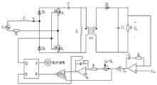
图2是电流连续模式单周期控制的带隔离的无桥SEPIC-PFC电路;Figure 2 is a bridgeless SEPIC-PFC circuit with isolation for current continuous mode single-cycle control;
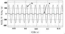
图3是电路中输出电压400V时交流侧输入电压与输入电流波形;Figure 3 is the AC side input voltage and input current waveforms when the output voltage is 400V in the circuit;
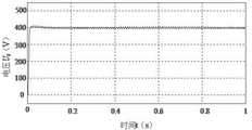
图4是电路中输出电压400V波形;Figure 4 is the output voltage 400V waveform in the circuit;
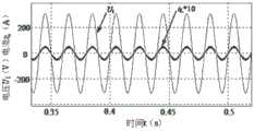
图5是电路中输出电压400V时交流侧输入电流放大波形;Figure 5 is the amplified waveform of the input current on the AC side when the output voltage in the circuit is 400V;
图6是电路中输出电压200V时交流侧输入电压与输入电流波形;Figure 6 is the AC side input voltage and input current waveforms when the output voltage is 200V in the circuit;
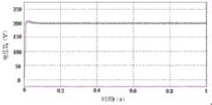
图7是电路中输出电压200V波形;Figure 7 is the output voltage 200V waveform in the circuit;
图8是电路中输出电压200V时交流侧输入电流放大波形。Figure 8 is the amplified waveform of the input current on the AC side when the output voltage is 200V in the circuit.
具体实施方式Detailed ways
以下结合附图和技术方案,进一步说明本发明的具体实施方式。The specific embodiments of the present invention will be further described below with reference to the accompanying drawings and technical solutions.
(1)积分器的搭建(1) Construction of the integrator
构造关于占空比D的一次函数,构造中使用一个积分器,实际电路中可使用LF412芯片和相应的电阻电容组成积分器。根据单周期控制在CCM(continuous conductionmode)电路中的原理,积分器的输出应为
占空比D的表达式计算过程如下:The calculation process of the expression of the duty cycle D is as follows:
计算电流连续型带隔离的无桥SEPIC-PFC电路的静态电压增益:Calculate the quiescent voltage gain of a current continuous bridgeless SEPIC-PFC circuit with isolation:


功率因数校正的目的是让交流输入电流跟随输入电压,即达到Ui=iL×ReThe purpose of power factor correction is to make the AC input current follow the input voltage, that is to achieve Ui =iL ×Re


令

iL×Rs×D=n×Um-n×Um×D (6)iL ×Rs ×D=n×Um -n×Um ×D (6)
(iL×Rs+n×Um)×D=n×Um (7)(iL ×Rs +n×Um )×D=n×Um (7)
式(7)为占空比D的表达式。Equation (7) is an expression of the duty ratio D.
在每个开关周期内均需要改变电路的占空比,为满足此条件,积分器在每个开关周期的起始时刻都要复位为单周期控制0,需要对控制电路添加复位开关,复位开关和积分器组成复位积分器,实际中可选用DG308作为复位开关。In each switching cycle, the duty cycle of the circuit needs to be changed. In order to meet this condition, the integrator must be reset to single-
(2)采样输出电压与电压基准值进行比较得到误差,将误差进行PI调节,通过选择合适的参数得到Um;搭建电路,构建占空比D的表达式,检测主电路的输入电流iL,输出电压Uo,构造占空比D,构造中使用一个积分器,根据单周期控制在CCM(continuous conductionmode)电路中的原理,积分器的输出应为
(3)脉冲宽度调制PWM信号(3) Pulse width modulation PWM signal
将积分器的输出(iL×Rs+n×Um)×D与n×Um相比较,差值作为RS触发器R端的输入信号,S端信号可由NE555构成多谐振荡器来得到50kHz的信号,RS触发器的输出端Q输出的信号用来控制主电路中开关的通断,
(4)为验证步骤(1)(2)(3)中分析的单周期控制方法的正确性,对电路进行PSIM仿真,可以根据下面的条件得到主电路中各个元件的参数,Ui=311sin(2π50t),Uo=400V,P=3000W,fs=50kHz,ΔiL=10%iL,n=1;仿真结果如附图3、附图4、附图5、附图6、附图7和附图8所示,其中附图3是交流输入电压波形与电流波形,从图3可以看到输入电流跟随输入电压变化,电路可以实现单位功率因数校正的目的;附图4是输出电压波形,可以得出输出电压能保持为稳定的400V直流电压;附图5是交流侧输入电流放大波形,可以得出变换器工作在电流连续模式;附图6、附图7、附图8是输出电压低于输入电压峰值(311V)情况下的仿真,附图6是在此种情况下交流输入电流iL和输出电压Ui的仿真波形,同样可以实现单位功率因数校正;附图7为输出电压波形,其输出直流电压为稳定的200V;附图8是交流侧输入电流放大波形,可以得出变换器工作在电流连续模式。(4) In order to verify the correctness of the single-cycle control method analyzed in steps (1) (2) (3), PSIM simulation is performed on the circuit, and the parameters of each element in the main circuit can be obtained according to the following conditions, Ui =311sin (2π50t), Uo =400V, P=3000W, fs =50kHz, ΔiL =10%iL , n=1; the simulation results are shown in Figure 3, Figure 4, Figure 5, Figure 6, and Figure 6 As shown in Figure 7 and Figure 8, Figure 3 shows the AC input voltage waveform and current waveform. It can be seen from Figure 3 that the input current changes with the input voltage, and the circuit can achieve the purpose of unity power factor correction; Figure 4 is the output Voltage waveform, it can be concluded that the output voltage can be maintained as a stable 400V DC voltage; Figure 5 is the AC side input current amplification waveform, it can be concluded that the converter works in the current continuous mode; Figure 6, Figure 7, Figure 8 It is the simulation under the situation that the output voltage is lower than the peak value of the input voltage (311V). Figure 6 is the simulation waveform of the AC input current iL and the output voltage Ui in this case, which can also achieve unity power factor correction; Figure 7 is the output voltage waveform, the output DC voltage is a stable 200V; Figure 8 is the AC side input current amplification waveform, it can be concluded that the converter works in the current continuous mode.
Claims (1)
Translated fromChinese


Priority Applications (1)
| Application Number | Priority Date | Filing Date | Title |
|---|---|---|---|
| CN202010930238.XACN112003485B (en) | 2020-09-07 | 2020-09-07 | Current Continuous Control Method Based on Bridgeless SEPIC-PFC Circuit |
Applications Claiming Priority (1)
| Application Number | Priority Date | Filing Date | Title |
|---|---|---|---|
| CN202010930238.XACN112003485B (en) | 2020-09-07 | 2020-09-07 | Current Continuous Control Method Based on Bridgeless SEPIC-PFC Circuit |
Publications (2)
| Publication Number | Publication Date |
|---|---|
| CN112003485Atrue CN112003485A (en) | 2020-11-27 |
| CN112003485B CN112003485B (en) | 2024-04-26 |
Family
ID=73469097
Family Applications (1)
| Application Number | Title | Priority Date | Filing Date |
|---|---|---|---|
| CN202010930238.XAActiveCN112003485B (en) | 2020-09-07 | 2020-09-07 | Current Continuous Control Method Based on Bridgeless SEPIC-PFC Circuit |
Country Status (1)
| Country | Link |
|---|---|
| CN (1) | CN112003485B (en) |
Cited By (4)
| Publication number | Priority date | Publication date | Assignee | Title |
|---|---|---|---|---|
| CN112953264A (en)* | 2021-03-18 | 2021-06-11 | 上海大学 | Bridgeless isolated switched capacitor SEPIC PFC converter |
| CN116581821A (en)* | 2023-07-12 | 2023-08-11 | 深圳天邦达科技有限公司 | Method for improving running stability of PFC weak current network |
| CN117060708A (en)* | 2023-08-21 | 2023-11-14 | 哈尔滨工业大学 | Single-stage bridgeless PFC converter and control method |
| CN119362902A (en)* | 2024-12-25 | 2025-01-24 | 西安麦格米特电气有限公司 | Power supply regulation circuit and method, power supply conversion circuit, and electronic equipment |
Citations (7)
| Publication number | Priority date | Publication date | Assignee | Title |
|---|---|---|---|---|
| US20060245219A1 (en)* | 2005-04-28 | 2006-11-02 | Yong Li | Digital implementation of power factor correction |
| US20130223119A1 (en)* | 2012-02-29 | 2013-08-29 | Silergy Semiconductor Technology (Hangzhou) Ltd | Boost pfc controller |
| CN103368421A (en)* | 2012-03-28 | 2013-10-23 | 株式会社万都 | Control circuit for discontinuous conduction mode power factor correction converter using harmonic modulation |
| US20140097808A1 (en)* | 2012-10-09 | 2014-04-10 | Delta-Q Technologies Corp. | Digital controller based detection methods for adaptive mixed conduction mode power factor correction circuit |
| CN104638900A (en)* | 2015-01-27 | 2015-05-20 | 大连理工大学 | One-cycle control method applied to bridgeless SEPIC-PFC (single-ended primary-inductor converter-power factor correction) circuit |
| TW201526699A (en)* | 2013-12-18 | 2015-07-01 | Univ Lunghwa Sci & Technology | Single-stage SEPIC LED driver with PFC function |
| US10027221B1 (en)* | 2017-09-14 | 2018-07-17 | Hua Cao | Method of generating a feedback signal in a switching regulator |
- 2020
- 2020-09-07CNCN202010930238.XApatent/CN112003485B/enactiveActive
Patent Citations (7)
| Publication number | Priority date | Publication date | Assignee | Title |
|---|---|---|---|---|
| US20060245219A1 (en)* | 2005-04-28 | 2006-11-02 | Yong Li | Digital implementation of power factor correction |
| US20130223119A1 (en)* | 2012-02-29 | 2013-08-29 | Silergy Semiconductor Technology (Hangzhou) Ltd | Boost pfc controller |
| CN103368421A (en)* | 2012-03-28 | 2013-10-23 | 株式会社万都 | Control circuit for discontinuous conduction mode power factor correction converter using harmonic modulation |
| US20140097808A1 (en)* | 2012-10-09 | 2014-04-10 | Delta-Q Technologies Corp. | Digital controller based detection methods for adaptive mixed conduction mode power factor correction circuit |
| TW201526699A (en)* | 2013-12-18 | 2015-07-01 | Univ Lunghwa Sci & Technology | Single-stage SEPIC LED driver with PFC function |
| CN104638900A (en)* | 2015-01-27 | 2015-05-20 | 大连理工大学 | One-cycle control method applied to bridgeless SEPIC-PFC (single-ended primary-inductor converter-power factor correction) circuit |
| US10027221B1 (en)* | 2017-09-14 | 2018-07-17 | Hua Cao | Method of generating a feedback signal in a switching regulator |
Non-Patent Citations (3)
| Title |
|---|
| 吕小刚;刘崇义;杨旭东;: "无桥PFC单周期控制技术", 科技创新导报, no. 13, pages 109 - 110* |
| 羊绛军;王立伟;王书强;贲洪奇;: "基于单周期控制策略的高效率无桥PFC电路", 电力电子技术, no. 07, pages 17 - 33* |
| 邱金燕, 单周期控制 的无桥式S EP IC 电路研究, pages 11 - 30* |
Cited By (6)
| Publication number | Priority date | Publication date | Assignee | Title |
|---|---|---|---|---|
| CN112953264A (en)* | 2021-03-18 | 2021-06-11 | 上海大学 | Bridgeless isolated switched capacitor SEPIC PFC converter |
| CN116581821A (en)* | 2023-07-12 | 2023-08-11 | 深圳天邦达科技有限公司 | Method for improving running stability of PFC weak current network |
| CN116581821B (en)* | 2023-07-12 | 2024-02-23 | 深圳天邦达科技有限公司 | Method for improving running stability of PFC weak current network |
| CN117060708A (en)* | 2023-08-21 | 2023-11-14 | 哈尔滨工业大学 | Single-stage bridgeless PFC converter and control method |
| CN117060708B (en)* | 2023-08-21 | 2024-05-24 | 哈尔滨工业大学 | Single-stage bridgeless PFC converter and control method |
| CN119362902A (en)* | 2024-12-25 | 2025-01-24 | 西安麦格米特电气有限公司 | Power supply regulation circuit and method, power supply conversion circuit, and electronic equipment |
Also Published As
| Publication number | Publication date |
|---|---|
| CN112003485B (en) | 2024-04-26 |
Similar Documents
| Publication | Publication Date | Title |
|---|---|---|
| CN112003485B (en) | Current Continuous Control Method Based on Bridgeless SEPIC-PFC Circuit | |
| CN108377102B (en) | Method for reducing capacitance in single-phase pulse load AC-DC power supply | |
| CN101986542B (en) | PFC (power factor correction) control method with high input power factor and control circuit thereof | |
| CN101764528B (en) | High power factor DCM Boost PFC converter | |
| US11601043B2 (en) | Control method and control circuit for an AC-DC power supply | |
| CN102355130A (en) | Double-tube Buck-Boost type PFC (Power Factor Correction) converter based on one-cycle control | |
| CN104038045B (en) | high power factor correction control circuit and device | |
| CN103166445A (en) | Power factor correction circuit capable of estimating input current and its control method | |
| CN104638900A (en) | One-cycle control method applied to bridgeless SEPIC-PFC (single-ended primary-inductor converter-power factor correction) circuit | |
| CN203933384U (en) | A kind of high power factor correction control circuit and device | |
| CN101951139B (en) | Power Factor Correction Circuit for Power Converter | |
| Naraharisetti et al. | Design and modeling of CCM average current control PFC AC-DC Boost converter | |
| CN102801301B (en) | Frequency control system and method applied to power factor corrector | |
| Shen et al. | A novel high-efficiency single-stage PFC converter with reduced voltage stress | |
| CN114448251B (en) | A Digitally Controlled Harmonic Compensation Circuit | |
| Powniker et al. | Development of active power factor correction controller using boost converter | |
| CN103475209A (en) | Non-electrolytic-capacitor high-power-factor correction device and method | |
| CN109309447B (en) | Constant switching frequency controlled CRM buck PFC converter | |
| CN203039585U (en) | Critical continuous mode unity power factor flyback converter | |
| Lin et al. | Digital control of boost PFC AC/DC converters with low THD and fast dynamic response | |
| CN116961400A (en) | High-efficiency bridgeless buck PFC converter without input diode | |
| CN207135002U (en) | A kind of ON time adjustment circuit and SEPIC power factor correcting converters | |
| CN116436282A (en) | Boost power factor correction circuit adopting coupling inductor | |
| de Souza et al. | Comparison of control techniques used in power factor correction rectifiers | |
| Qi et al. | Dual-boost PFC converter control without input current sensing |
Legal Events
| Date | Code | Title | Description |
|---|---|---|---|
| PB01 | Publication | ||
| PB01 | Publication | ||
| SE01 | Entry into force of request for substantive examination | ||
| SE01 | Entry into force of request for substantive examination | ||
| GR01 | Patent grant | ||
| GR01 | Patent grant |