CN112002243A - Modular pull-out exercise mechanism - Google Patents
Modular pull-out exercise mechanismDownload PDFInfo
- Publication number
- CN112002243A CN112002243ACN202010988534.5ACN202010988534ACN112002243ACN 112002243 ACN112002243 ACN 112002243ACN 202010988534 ACN202010988534 ACN 202010988534ACN 112002243 ACN112002243 ACN 112002243A
- Authority
- CN
- China
- Prior art keywords
- seat
- casing
- movable seat
- pull
- fixedly connected
- Prior art date
- Legal status (The legal status is an assumption and is not a legal conclusion. Google has not performed a legal analysis and makes no representation as to the accuracy of the status listed.)
- Granted
Links
- 230000007246mechanismEffects0.000titleclaimsabstractdescription29
- 230000033001locomotionEffects0.000claimsabstractdescription38
- 230000005540biological transmissionEffects0.000claimsabstractdescription27
- 238000006073displacement reactionMethods0.000claimsabstractdescription15
- 230000001360synchronised effectEffects0.000claimsabstractdescription14
- 238000011084recoveryMethods0.000claimsabstractdescription10
- 230000002146bilateral effectEffects0.000claimsabstractdescription4
- 238000000926separation methodMethods0.000claimsdescription6
- 238000004064recyclingMethods0.000claimsdescription2
- 238000000034methodMethods0.000abstractdescription10
- 230000009471actionEffects0.000abstractdescription5
- 230000008569processEffects0.000abstractdescription3
- 238000010586diagramMethods0.000description3
- 230000009286beneficial effectEffects0.000description2
- 238000004519manufacturing processMethods0.000description2
- 238000005034decorationMethods0.000description1
- 230000007812deficiencyEffects0.000description1
- 230000006872improvementEffects0.000description1
- 238000009776industrial productionMethods0.000description1
- 230000035515penetrationEffects0.000description1
Images


Classifications
- G—PHYSICS
- G09—EDUCATION; CRYPTOGRAPHY; DISPLAY; ADVERTISING; SEALS
- G09F—DISPLAYING; ADVERTISING; SIGNS; LABELS OR NAME-PLATES; SEALS
- G09F9/00—Indicating arrangements for variable information in which the information is built-up on a support by selection or combination of individual elements
- G09F9/30—Indicating arrangements for variable information in which the information is built-up on a support by selection or combination of individual elements in which the desired character or characters are formed by combining individual elements
- G09F9/301—Indicating arrangements for variable information in which the information is built-up on a support by selection or combination of individual elements in which the desired character or characters are formed by combining individual elements flexible foldable or roll-able electronic displays, e.g. thin LCD, OLED
Landscapes
- Physics & Mathematics (AREA)
- General Physics & Mathematics (AREA)
- Engineering & Computer Science (AREA)
- Theoretical Computer Science (AREA)
- Seats For Vehicles (AREA)
Abstract
Translated fromChinese
Description
Translated fromChinese技术领域technical field
本发明涉及柔性屏应用技术领域,尤其涉及一种模块化的抽拉式运动机构。The invention relates to the technical field of flexible screen applications, in particular to a modular pull-out motion mechanism.
背景技术Background technique
柔性屏幕,指的是柔性OLED。柔性屏幕的成功量产不仅重大利好于新一代高端智能手机的制造,也因其低功耗、可弯曲的特性对可穿戴式设备的应用带来深远的影响,未来柔性屏幕将随着个人智能终端的不断渗透而广泛应用。柔性屏手机是指采用可弯曲、柔韧性佳屏幕的手机,因为形似芒卷,又被称为卷芒手机。相较于传统屏幕,柔性屏幕优势明显,不仅在体积上更加轻薄,功耗上也低于原有器件,有助于提升设备的续航能力,同时基于其可弯曲、柔韧性佳的特性,其耐用程度也大大高于以往屏幕,降低设备意外损伤的概率。Flexible screen refers to flexible OLED. The successful mass production of flexible screens is not only beneficial to the manufacture of a new generation of high-end smartphones, but also has a profound impact on the application of wearable devices due to its low power consumption and bendable characteristics. The continuous penetration of the terminal is widely used. Flexible screen mobile phone refers to a mobile phone with a bendable and flexible screen. Compared with traditional screens, flexible screens have obvious advantages. They are not only lighter and thinner in size, but also lower in power consumption than original devices, which helps to improve the battery life of the device. The degree of durability is also much higher than that of previous screens, reducing the probability of accidental damage to the equipment.
要实现柔性屏折叠功能,除了屏幕本身之外,实现折叠的连接组件,即折弯处的连接轴设计亦是最大的技术难题。柔性屏的打开方式除了外折及内折外,还有多种方式,其中抽拉式的展开方式为其中之一,为了满足结构简化,使其工业化生产的成本降低,并降低工业化难度,需要考虑模块化的设计来实现不同环节的合理化加工,因此需要将整个执行抽拉的运动机构独立出来,执行抽拉动作的机构完全模块化实现才能满足需求。To realize the folding function of the flexible screen, in addition to the screen itself, the connecting components to realize the folding, that is, the design of the connecting shaft at the bend is also the biggest technical problem. In addition to outward folding and inward folding, there are many ways to open the flexible screen, among which the pull-out unfolding method is one of them. In order to simplify the structure, reduce the cost of industrial production, and reduce the difficulty of industrialization, it is necessary to Considering the modular design to realize the rational processing of different links, it is necessary to separate the entire motion mechanism for performing the pulling action, and the mechanism for performing the pulling action is completely modularized to meet the needs.
发明内容SUMMARY OF THE INVENTION
本发明的目的在于克服现有技术中的不足之处而提供一种模块化的抽拉式运动机构。The purpose of the present invention is to overcome the deficiencies in the prior art and provide a modular pull-out motion mechanism.
为实现上述目的,本发明采用如下的技术方案:For achieving the above object, the present invention adopts the following technical scheme:
一种模块化的抽拉式运动机构,包括抽拉式的结构主体,所述结构主体由双边的机壳及与所述机壳固定连接并实现独立同步抽拉的运动组件组成,所述运动组件由固定座及与之抽拉滑动的活动座组成;所述固定座及活动座之间设有传动单元及相对位移单元,所述相对位移单元由导轨轴及实现相对运动的第二导轨轴及第三导轨轴组成,或所述相对位移单元由一组导轨轴及实现相对位移的第一滑轨及第二滑轨组成,所述第二滑轨内设有多组与所述第一滑轨相对滑动的滑轮;A modular pull-out motion mechanism, comprising a pull-out structure main body, the structure main body is composed of a bilateral casing and a moving component that is fixedly connected to the casing and realizes independent synchronous pull-out. The assembly consists of a fixed seat and a movable seat that pulls and slides with it; a transmission unit and a relative displacement unit are arranged between the fixed seat and the movable seat, and the relative displacement unit consists of a guide rail shaft and a second guide rail shaft that realizes relative movement. and a third guide rail shaft, or the relative displacement unit is composed of a set of guide rail shafts and a first slide rail and a second slide rail that realize relative displacement. A pulley that slides relative to each other;
所述固定座上设有实现卡点座,所述卡点座上设有实现拉开和闭合时卡点定位的卡点弹簧,所述导轨轴上设有实现弹力及张力的张力弹簧。The fixing seat is provided with a snap-point seat, the snap-point seat is provided with a snap-point spring for realizing snap-point positioning when opening and closing, and a tension spring for realizing elastic force and tension is provided on the guide rail shaft.
特别的,所述传动单元由活动座上纵向设置的第一定位板、第二定位板、传动轴及横向设置的链轮及传动带组成,所述传动带包括组合连接的皮带及皮带板;In particular, the transmission unit is composed of a first positioning plate, a second positioning plate, a transmission shaft, a sprocket and a transmission belt arranged longitudinally on the movable seat, and the transmission belt includes a combined belt and a belt plate;
所述皮带一端与与所述第一定位板固定,另一端与所述链轮组合实现固定座及活动座的分离与回收;One end of the belt is fixed with the first positioning plate, and the other end is combined with the sprocket to realize the separation and recovery of the fixed seat and the movable seat;
所述皮带板与所述传动轴同步连接,且所述皮带板一端与所述第一定位板及第二定位板固定连接,所述皮带板与所述皮带组成闭合回路实现固定座及活动座的分离与回收。The belt plate is synchronously connected with the transmission shaft, and one end of the belt plate is fixedly connected with the first positioning plate and the second positioning plate. The belt plate and the belt form a closed loop to realize a fixed seat and a movable seat separation and recycling.
特别的,所述传动轴两端与所述固定座连接处分别设有电机座,所述电机座内设有连接、定位并驱动所述运动组件转动的马达,所述马达为正反转马达。In particular, two ends of the transmission shaft are connected with the fixed seat respectively with a motor seat, the motor seat is provided with a motor for connecting, positioning and driving the rotation of the moving component, and the motor is a forward and reverse rotation motor .
特别的,所述第二滑轨与所述滑轮之间设有实现连接定位的定位销。In particular, a positioning pin for connecting and positioning is provided between the second slide rail and the pulley.
特别的,所述机壳包括第一机壳及第二机壳,所述第一机壳与所述固定座固定连接并同步,所述第二机壳与所述活动座固定连接并同步,所述第一机壳与第二机壳之间固定设有实现同步抽拉的柔性屏组件。In particular, the casing includes a first casing and a second casing, the first casing is fixedly connected and synchronized with the fixed base, and the second casing is fixedly connected and synchronized with the movable base, A flexible screen assembly for realizing synchronous pulling and pulling is fixed between the first casing and the second casing.
特别的,所述导轨轴设置于所述活动座上,所述第二导轨轴一端与所述活动座固定连接,另一端与所述固定座相对滑动,所述第三导轨轴一端与所述固定座连接,另一端与所述活动座相对滑动。In particular, the guide rail shaft is arranged on the movable seat, one end of the second guide rail shaft is fixedly connected to the movable seat, the other end slides relatively with the fixed seat, and one end of the third guide rail shaft is connected to the movable seat. The fixed seat is connected, and the other end slides relatively with the movable seat.
特别的,所述导轨轴设置于所述活动座上,所述第一滑轨与所述活动座固定连接,所述第二滑轨与所述固定座固定连接,所述第一滑轨与所述第二滑轨相对滑动带动所述活动座与所述固定座相对运动。In particular, the guide rail shaft is arranged on the movable seat, the first sliding rail is fixedly connected to the movable seat, the second sliding rail is fixedly connected to the fixed seat, and the first sliding rail is fixedly connected to the movable seat. The relative sliding of the second slide rail drives the relative movement of the movable seat and the fixed seat.
本发明的有益效果在于:本发明提供的模块化的抽拉式运动机构,通过电机带动传动带与链轮同步并产生相对运动,从而带动固定座与活动座的展开与回收,机壳与运动组件固定,且运动组件模块式实现独立的抽拉,即机壳与柔性屏组件通过活动座与固定座实现被动抽拉传动,本身不参与动作执行,使其运动组件作为独立的运动模块,实现了机壳的替换式装配使用,使其工业化难度大大降低,装配过程更加简单,使用更加方便。The beneficial effects of the present invention are: the modular pull-out motion mechanism provided by the present invention drives the transmission belt and the sprocket to synchronize and produce relative motion through the motor, thereby driving the unfolding and recovery of the fixed seat and the movable seat, and the casing and the moving assembly. Fixed, and the moving component is modular to achieve independent pulling, that is, the chassis and the flexible screen component realize passive pulling and transmission through the movable seat and the fixed seat, and do not participate in the execution of the action itself, so that the moving component acts as an independent motion module, realizing the The replacement assembly of the casing greatly reduces the difficulty of industrialization, the assembly process is simpler, and the use is more convenient.
附图说明Description of drawings
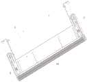
图1是本发明模块化的抽拉式运动机构展开状态图。FIG. 1 is a state view of the modularized pull-out motion mechanism of the present invention in an unfolded state.
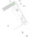
图2 是本发明模块化的抽拉式运动机构回收状态图。FIG. 2 is a recovery state diagram of the modular pull-out motion mechanism of the present invention.
图3 是本发明模块化的抽拉式运动机构内部展开图之一。FIG. 3 is one of the internal development views of the modular pull-out motion mechanism of the present invention.
图4是本发明模块化的抽拉式运动机构内部展开图之二。Figure 4 is the second internal development view of the modular pull-out motion mechanism of the present invention.
图5是本发明模块化的抽拉式运动机构外部分解图之一。Fig. 5 is one of the external exploded views of the modular pull-out motion mechanism of the present invention.
图6是本发明模块化的抽拉式运动机构外部分解图之二。FIG. 6 is the second exploded view of the exterior of the modular pull-out motion mechanism of the present invention.
图7是本发明模块化的抽拉式运动机构内部分解图之一。FIG. 7 is one of the internal exploded views of the modular pull-out motion mechanism of the present invention.
图8是本发明模块化的抽拉式运动机构内部分解图之二。Fig. 8 is the second exploded view of the interior of the modular pull-out motion mechanism of the present invention.
图9是本发明模块化的抽拉式运动机构中运动组件回收结构图之一。FIG. 9 is one of the structural diagrams of the recovery of moving components in the modular pull-out motion mechanism of the present invention.
图10是本发明模块化的抽拉式运动机构中运动组件回收结构图之二。Fig. 10 is the second structural diagram of the recovery structure of the moving components in the modular pull-out moving mechanism of the present invention.
图11是本发明模块化的抽拉式运动机构中运动组件展开结构图之一。FIG. 11 is one of the unfolded structural views of the movement components in the modular pull-out movement mechanism of the present invention.
图12是本发明模块化的抽拉式运动机构中运动组件展开结构图之二。Fig. 12 is the second expanded structural view of the moving components in the modular pull-out moving mechanism of the present invention.
具体实施方式Detailed ways
以下结合说明书附图对本发明作进一步说明:The present invention will be further described below in conjunction with the accompanying drawings:
实施例1:Example 1:
如图1-12所示,本实施例公开的一种模块化的抽拉式运动机构,包括抽拉式的结构主体1,所述结构主体1由双边的机壳2及与所述机壳2固定连接并实现独立同步抽拉的运动组件3组成,所述运动组件3由固定座4及与之抽拉滑动的活动座5组成;所述固定座4及活动座5之间设有传动单元6及相对位移单元7,所述相对位移单元7由导轨轴8及实现相对运动的第二导轨轴9及第三导轨轴10组成,或所述相对位移单元7由一组导轨轴8及实现相对位移的第一滑轨11及第二滑轨12组成,所述第二滑轨12内设有多组与所述第一滑轨11相对滑动的滑轮13;As shown in FIGS. 1-12 , a modular pull-out motion mechanism disclosed in this embodiment includes a pull-out structure
所述固定座4上设有实现卡点座14,所述卡点座14上设有实现拉开和闭合时卡点定位的卡点弹簧15,所述导轨轴8上设有实现弹力及张力的张力弹簧16。The fixed
申请人声明,所属技术领域的技术人员在上述实施例的基础上,将上述实施例某步骤,与发明内容部分的技术方案相组合,从而产生的新的方法,也是本发明的记载范围之一,本申请为使说明书简明,不再罗列这些步骤的其它实施方式。The applicant declares that, on the basis of the above-mentioned embodiments, those skilled in the art combine a certain step of the above-mentioned embodiments with the technical solutions in the content of the invention, thereby generating a new method, which is also one of the recording scopes of the present invention. , this application will not list other implementations of these steps for the sake of simplicity of the description.
上述实施例中,所述传动单元6由活动座5上纵向设置的第一定位板17、第二定位板18、传动轴19及横向设置的链轮20及传动带21组成,所述传动带21包括组合连接的皮带211及皮带板212;In the above embodiment, the
所述皮带211一端与与所述第一定位板17固定,另一端与所述链轮20组合实现固定座4及活动座5的分离与回收;One end of the
所述皮带板212与所述传动轴19同步连接,且所述皮带板212一端与所述第一定位板17及第二定位板18固定连接,所述皮带板212与所述皮带211组成闭合回路实现固定座4及活动座5的分离与回收。The
所述传动轴19两端与所述固定座4连接处分别设有电机座22,所述电机座22内设有连接、定位并驱动所述运动组件3转动的马达23,所述马达23为正反转马达。The two ends of the
所述第二滑轨12与所述滑轮13之间设有实现连接定位的定位销24。所述机壳2包括第一机壳251及第二机壳252,所述第一机壳251与所述固定座4固定连接并同步,所述第二机壳252与所述活动座5固定连接并同步,所述第一机壳251与第二机壳252之间固定设有实现同步抽拉的柔性屏组件253。所述导轨轴8设置于所述活动座5上,所述第二导轨轴9一端与所述活动座5固定连接,另一端与所述固定座4相对滑动,所述第三导轨轴10一端与所述固定座4连接,另一端与所述活动座相5对滑动。所述导轨轴9设置于所述活动座5上,所述第一滑轨11与所述活动座5固定连接,所述第二滑轨12与所述固定座4固定连接,所述第一滑轨11与所述第二滑轨12相对滑动带动所述活动座5与所述固定座4相对运动。A
申请人又一声明,本发明通过上述实施例来说明本发明的实现方法及装置结构,但本发明并不局限于上述实施方式,即不意味着本发明必须依赖上述方法及结构才能实施。所属技术领域的技术人员应该明了,对本发明的任何改进,对本发明所选用实现方法等效替换及步骤的添加、具体方式的选择等,均落在本发明的保护范围和公开范围之内。The applicant further declares that the present invention illustrates the implementation method and device structure of the present invention through the above-mentioned embodiments, but the present invention is not limited to the above-mentioned embodiments, that is, it does not mean that the present invention must rely on the above-mentioned method and structure to be implemented. Those skilled in the art should understand that any improvement of the present invention, the equivalent replacement of the selected implementation method of the present invention, the addition of steps, the selection of specific methods, etc., all fall within the protection scope and disclosure scope of the present invention.
本实施例技术原理:The technical principle of this embodiment:
本实施例提供的模块化的抽拉式运动机构,通过电机带动传动带与链轮同步并产生相对运动,从而带动固定座与活动座的展开与回收,机壳与运动组件固定,且运动组件模块式实现独立的抽拉,即机壳与柔性屏组件通过活动座与固定座实现被动抽拉传动,本身不参与动作执行,使其运动组件作为独立的运动模块,实现了机壳的替换式装配使用,使其工业化难度大大降低,装配过程更加简单,使用更加方便。The modular pull-out motion mechanism provided in this embodiment uses the motor to drive the transmission belt and the sprocket to synchronize and generate relative motion, thereby driving the expansion and recovery of the fixed seat and the movable seat, the casing and the moving component are fixed, and the moving component module It realizes independent pulling and pulling, that is, the casing and the flexible screen assembly realize passive pulling and pulling transmission through the movable seat and the fixed seat, and do not participate in the execution of the action itself, so that the moving assembly can be used as an independent movement module to realize the replacement assembly of the casing. Use, the difficulty of industrialization is greatly reduced, the assembly process is simpler, and the use is more convenient.
以上所述仅是对本发明的较佳实施例,并非对本发明的范围进行限定,故在不脱离本发明设计精神的前提下,本领域普通工程技术人员对本发明所述的构造、特征及原理所做的等效变化或装饰,均应落入本发明申请专利的保护范围内。The above descriptions are only preferred embodiments of the present invention, and do not limit the scope of the present invention. Therefore, without departing from the design spirit of the present invention, those skilled in the art can understand the structure, features and principles of the present invention. The equivalent changes or decorations made shall fall within the protection scope of the patent application of the present invention.
Claims (7)
Translated fromChinesePriority Applications (1)
| Application Number | Priority Date | Filing Date | Title |
|---|---|---|---|
| CN202010988534.5ACN112002243B (en) | 2020-09-18 | 2020-09-18 | Modular pull-out kinematics |
Applications Claiming Priority (1)
| Application Number | Priority Date | Filing Date | Title |
|---|---|---|---|
| CN202010988534.5ACN112002243B (en) | 2020-09-18 | 2020-09-18 | Modular pull-out kinematics |
Publications (2)
| Publication Number | Publication Date |
|---|---|
| CN112002243Atrue CN112002243A (en) | 2020-11-27 |
| CN112002243B CN112002243B (en) | 2024-11-15 |
Family
ID=73474302
Family Applications (1)
| Application Number | Title | Priority Date | Filing Date |
|---|---|---|---|
| CN202010988534.5AActiveCN112002243B (en) | 2020-09-18 | 2020-09-18 | Modular pull-out kinematics |
Country Status (1)
| Country | Link |
|---|---|
| CN (1) | CN112002243B (en) |
Citations (5)
| Publication number | Priority date | Publication date | Assignee | Title |
|---|---|---|---|---|
| CN206557661U (en)* | 2017-02-28 | 2017-10-13 | 宇龙计算机通信科技(深圳)有限公司 | The telescopic terminal of screen |
| EP3525436A1 (en)* | 2018-02-09 | 2019-08-14 | Guangdong Oppo Mobile Telecommunications Corp., Ltd. | Mobile terminal |
| CN110428732A (en)* | 2019-07-20 | 2019-11-08 | 张拥银 | A kind of drawing and pulling type flexible screen |
| CN110545342A (en)* | 2019-09-03 | 2019-12-06 | 深圳传音控股股份有限公司 | a mobile terminal |
| CN213123614U (en)* | 2020-09-18 | 2021-05-04 | 东莞市劲丰电子有限公司 | Modular pull-out exercise mechanism |
- 2020
- 2020-09-18CNCN202010988534.5Apatent/CN112002243B/enactiveActive
Patent Citations (5)
| Publication number | Priority date | Publication date | Assignee | Title |
|---|---|---|---|---|
| CN206557661U (en)* | 2017-02-28 | 2017-10-13 | 宇龙计算机通信科技(深圳)有限公司 | The telescopic terminal of screen |
| EP3525436A1 (en)* | 2018-02-09 | 2019-08-14 | Guangdong Oppo Mobile Telecommunications Corp., Ltd. | Mobile terminal |
| CN110428732A (en)* | 2019-07-20 | 2019-11-08 | 张拥银 | A kind of drawing and pulling type flexible screen |
| CN110545342A (en)* | 2019-09-03 | 2019-12-06 | 深圳传音控股股份有限公司 | a mobile terminal |
| CN213123614U (en)* | 2020-09-18 | 2021-05-04 | 东莞市劲丰电子有限公司 | Modular pull-out exercise mechanism |
Also Published As
| Publication number | Publication date |
|---|---|
| CN112002243B (en) | 2024-11-15 |
Similar Documents
| Publication | Publication Date | Title |
|---|---|---|
| WO2021259340A1 (en) | Folding apparatus and electronic device | |
| CN111882994A (en) | Manual-automatic flexible screen drawing mechanism based on gear and rack application | |
| CN111968508B (en) | Manual and automatic flexible screen pulling mechanism | |
| CN110442196A (en) | Rotating mechanism, Folding display terminal | |
| CN113194179B (en) | Electronic equipment | |
| CN113194180B (en) | Electronic equipment | |
| CN111899647A (en) | Automatic drawing type stretching and contracting mechanism applied to flexible screen | |
| CN217849479U (en) | Rotating shaft mechanism and foldable equipment | |
| CN114338875B (en) | Electronic devices | |
| CN112901649B (en) | A three-section inner folding hinge | |
| CN110131299A (en) | Flexible screen internal and external double-fold synchronous rotation mechanism | |
| CN113194178B (en) | Electronic equipment | |
| CN217152623U (en) | An inner folding hinge and terminal device applied to a mobile terminal | |
| CN118855839A (en) | A rotating shaft mechanism and electronic equipment | |
| CN112863331B (en) | Display device | |
| CN112002243A (en) | Modular pull-out exercise mechanism | |
| CN115875355A (en) | Hinge components and electronics | |
| CN216519159U (en) | Synchronous turnover damping mechanism for folding flexible screen and folding hinge | |
| CN211123830U (en) | Rotating mechanism and folding display terminal | |
| CN112911038B (en) | Electronic equipment | |
| CN213123614U (en) | Modular pull-out exercise mechanism | |
| CN117128229B (en) | Folding mechanism and foldable electronic equipment | |
| CN211474655U (en) | Inward-folding drop-shaped synchronous rotating mechanism | |
| CN114373383A (en) | Foldable display device | |
| CN216951255U (en) | Double groove nail support rod water drop rotation mechanism |
Legal Events
| Date | Code | Title | Description |
|---|---|---|---|
| PB01 | Publication | ||
| PB01 | Publication | ||
| SE01 | Entry into force of request for substantive examination | ||
| SE01 | Entry into force of request for substantive examination | ||
| CB02 | Change of applicant information | ||
| CB02 | Change of applicant information | Address after:No. 2, Shangli Road, Shipai Town, Dongguan City, Guangdong Province, 523000 Applicant after:DONGGUAN JINFENG ELECTRONIC Co.,Ltd. Address before:523000 Puxin Industrial Zone, Shipai Town, Dongguan City, Guangdong Province Applicant before:DONGGUAN JINFENG ELECTRONIC Co.,Ltd. | |
| GR01 | Patent grant | ||
| GR01 | Patent grant |