CN111999583B - Fault trip judging method of safety and stability control device suitable for alternating current power grid - Google Patents
Fault trip judging method of safety and stability control device suitable for alternating current power gridDownload PDFInfo
- Publication number
- CN111999583B CN111999583BCN202010854327.0ACN202010854327ACN111999583BCN 111999583 BCN111999583 BCN 111999583BCN 202010854327 ACN202010854327 ACN 202010854327ACN 111999583 BCN111999583 BCN 111999583B
- Authority
- CN
- China
- Prior art keywords
- phase
- fault
- voltage
- current
- tripping
- Prior art date
- Legal status (The legal status is an assumption and is not a legal conclusion. Google has not performed a legal analysis and makes no representation as to the accuracy of the status listed.)
- Active
Links
- 238000000034methodMethods0.000titleclaimsabstractdescription35
- 230000008859changeEffects0.000claimsabstractdescription47
- 239000002131composite materialSubstances0.000claimsabstractdescription25
- 238000004088simulationMethods0.000claimsabstractdescription21
- 230000002159abnormal effectEffects0.000claimsabstractdescription7
- 230000016507interphaseEffects0.000claimsabstract2
- 230000009471actionEffects0.000claimsdescription9
- 230000001965increasing effectEffects0.000claimsdescription9
- 230000035772mutationEffects0.000claimsdescription7
- 230000010355oscillationEffects0.000abstractdescription31
- 230000005540biological transmissionEffects0.000abstractdescription11
- 230000008569processEffects0.000abstractdescription10
- 230000007423decreaseEffects0.000abstractdescription7
- 230000000694effectsEffects0.000abstractdescription2
- 238000010586diagramMethods0.000description24
- 238000004458analytical methodMethods0.000description7
- 238000011161developmentMethods0.000description5
- 230000000737periodic effectEffects0.000description5
- 238000012795verificationMethods0.000description4
- 238000013508migrationMethods0.000description3
- 230000005012migrationEffects0.000description3
- 230000009467reductionEffects0.000description3
- 101000827703Homo sapiens Polyphosphoinositide phosphataseProteins0.000description2
- 101100499229Mus musculus Dhrsx geneProteins0.000description2
- 102100023591Polyphosphoinositide phosphataseHuman genes0.000description2
- 230000009286beneficial effectEffects0.000description2
- 238000012850discrimination methodMethods0.000description2
- 238000012986modificationMethods0.000description2
- 230000004048modificationEffects0.000description2
- 101100012902Saccharomyces cerevisiae (strain ATCC 204508 / S288c) FIG2 geneProteins0.000description1
- 101100233916Saccharomyces cerevisiae (strain ATCC 204508 / S288c) KAR5 geneProteins0.000description1
- 238000004364calculation methodMethods0.000description1
- 238000007405data analysisMethods0.000description1
- 238000013480data collectionMethods0.000description1
- 230000003247decreasing effectEffects0.000description1
- 230000005611electricityEffects0.000description1
- 238000005516engineering processMethods0.000description1
- 230000001939inductive effectEffects0.000description1
- 238000002955isolationMethods0.000description1
- 238000012423maintenanceMethods0.000description1
- 238000011160researchMethods0.000description1
- 230000006641stabilisationEffects0.000description1
- 238000011105stabilizationMethods0.000description1
- 230000001360synchronised effectEffects0.000description1
- 230000009885systemic effectEffects0.000description1
Images


Classifications
- G—PHYSICS
- G01—MEASURING; TESTING
- G01R—MEASURING ELECTRIC VARIABLES; MEASURING MAGNETIC VARIABLES
- G01R31/00—Arrangements for testing electric properties; Arrangements for locating electric faults; Arrangements for electrical testing characterised by what is being tested not provided for elsewhere
- G—PHYSICS
- G01—MEASURING; TESTING
- G01R—MEASURING ELECTRIC VARIABLES; MEASURING MAGNETIC VARIABLES
- G01R19/00—Arrangements for measuring currents or voltages or for indicating presence or sign thereof
- G01R19/165—Indicating that current or voltage is either above or below a predetermined value or within or outside a predetermined range of values
- G01R19/16566—Circuits and arrangements for comparing voltage or current with one or several thresholds and for indicating the result not covered by subgroups G01R19/16504, G01R19/16528, G01R19/16533
- G01R19/16571—Circuits and arrangements for comparing voltage or current with one or several thresholds and for indicating the result not covered by subgroups G01R19/16504, G01R19/16528, G01R19/16533 comparing AC or DC current with one threshold, e.g. load current, over-current, surge current or fault current
- G—PHYSICS
- G01—MEASURING; TESTING
- G01R—MEASURING ELECTRIC VARIABLES; MEASURING MAGNETIC VARIABLES
- G01R19/00—Arrangements for measuring currents or voltages or for indicating presence or sign thereof
- G01R19/165—Indicating that current or voltage is either above or below a predetermined value or within or outside a predetermined range of values
- G01R19/16566—Circuits and arrangements for comparing voltage or current with one or several thresholds and for indicating the result not covered by subgroups G01R19/16504, G01R19/16528, G01R19/16533
- G01R19/16576—Circuits and arrangements for comparing voltage or current with one or several thresholds and for indicating the result not covered by subgroups G01R19/16504, G01R19/16528, G01R19/16533 comparing DC or AC voltage with one threshold
- G—PHYSICS
- G01—MEASURING; TESTING
- G01R—MEASURING ELECTRIC VARIABLES; MEASURING MAGNETIC VARIABLES
- G01R23/00—Arrangements for measuring frequencies; Arrangements for analysing frequency spectra
- G01R23/005—Circuits for comparing several input signals and for indicating the result of this comparison, e.g. equal, different, greater, smaller (comparing phase or frequency of 2 mutually independent oscillations in demodulators)
- G—PHYSICS
- G01—MEASURING; TESTING
- G01R—MEASURING ELECTRIC VARIABLES; MEASURING MAGNETIC VARIABLES
- G01R25/00—Arrangements for measuring phase angle between a voltage and a current or between voltages or currents
- H—ELECTRICITY
- H02—GENERATION; CONVERSION OR DISTRIBUTION OF ELECTRIC POWER
- H02H—EMERGENCY PROTECTIVE CIRCUIT ARRANGEMENTS
- H02H7/00—Emergency protective circuit arrangements specially adapted for specific types of electric machines or apparatus or for sectionalised protection of cable or line systems, and effecting automatic switching in the event of an undesired change from normal working conditions
- H02H7/26—Sectionalised protection of cable or line systems, e.g. for disconnecting a section on which a short-circuit, earth fault, or arc discharge has occured
- H02H7/28—Sectionalised protection of cable or line systems, e.g. for disconnecting a section on which a short-circuit, earth fault, or arc discharge has occured for meshed systems
Landscapes
- Physics & Mathematics (AREA)
- General Physics & Mathematics (AREA)
- Engineering & Computer Science (AREA)
- Power Engineering (AREA)
- Supply And Distribution Of Alternating Current (AREA)
Abstract
Translated fromChinese
Description
Translated fromChinese技术领域Technical Field
本发明属于电力系统安全稳定控制技术领域,具体涉及一种适应交流电网的安全稳定控制装置故障跳闸判别方法。The invention belongs to the technical field of power system safety and stability control, and in particular relates to a fault tripping judgment method for a safety and stability control device adapted to an alternating current power grid.
背景技术Background Art
随着大型电网的发展,世界各国为了满足本国电力需求,电网的发展趋势从单一孤立走向互联互通,从小规模转向大规模,从国内地区互联转为跨国互联,跨国互联电网的发展势在必行。为保证跨国互联电网系统的安全稳定运行,对安全稳定控制安全性的要求达到了一个空前的高度。如果不及时处理电力系统中的扰动,可能会发展成系统性事故,甚至可能造成区域大面积停电。因此,安全稳定控制装置作为维持电力系统安全稳定和可靠运行的必备装置,是否正确动作将直接影响到电网的安全稳定运行。With the development of large-scale power grids, in order to meet the electricity needs of various countries in the world, the development trend of power grids has changed from single isolation to interconnection, from small scale to large scale, and from domestic regional interconnection to cross-border interconnection. The development of cross-border interconnected power grids is imperative. In order to ensure the safe and stable operation of cross-border interconnected power grid systems, the requirements for safety and stability control have reached an unprecedented level. If the disturbance in the power system is not handled in time, it may develop into a systemic accident and may even cause a large-scale power outage in the region. Therefore, as a necessary device to maintain the safe, stable and reliable operation of the power system, the correct operation of the safety and stability control device will directly affect the safe and stable operation of the power grid.
南方电网跨国输电技术的迅猛发展,使得区域电网间联系更加紧密。南方电网即将与东南亚一些国家电网交流互联,如中老两国即将在2021年左右实施500kV交流互联,这将是国内首次进行跨国交流电网互联。跨国电网运行的安全性事关国家形象及政治民生,必须超前分析跨国交流互联可能带来的安全风险,提前防范,在通报相关国家取得共识后,共防和共担风险。而电网详细的拓扑结构、网络参数、实时运行信息等均为国家机密,国家间不可能相互完全共享。而大容量、远距离等新形式电力输电方式的发展,使电力系统的稳定问题比以往更加突出,一旦出现危及系统稳定的事故,将波及多个区域电网,其危害性更大。因此,电网的安全稳定运行必须快速、准确识别电网中的故障并迅速及时采取措施。The rapid development of the cross-border power transmission technology of the Southern Power Grid has made the connection between regional power grids closer. The Southern Power Grid is about to interconnect with the power grids of some Southeast Asian countries. For example, China and Laos will implement 500kV AC interconnection around 2021. This will be the first cross-border AC power grid interconnection in China. The safety of cross-border power grid operation is related to the national image and political livelihood. It is necessary to analyze the security risks that may be brought about by cross-border exchange and interconnection in advance, take precautions in advance, and jointly prevent and share risks after informing the relevant countries and reaching a consensus. The detailed topological structure, network parameters, and real-time operation information of the power grid are all state secrets, and it is impossible for countries to fully share them with each other. The development of new forms of power transmission such as large capacity and long distance has made the stability of the power system more prominent than before. Once an accident that endangers the stability of the system occurs, it will affect multiple regional power grids, which is more harmful. Therefore, the safe and stable operation of the power grid must quickly and accurately identify faults in the power grid and take prompt and timely measures.
跨国交流电网初期为弱联系系统,且东南亚国家中不少潜在交流联网国家的电网结构均较弱。在初期就需要考虑到频率超限、振荡、过电流、过电压、低电压等问题对己方电网造成的影响。本发明针对不完备信息下的跨国交流互联电网,通过仿真模拟联络线上发生的故障跳闸状态进行数据采集分析,制定适用于中国-老挝边境某一特定区域目标场景下的联络线故障跳闸判据。The transnational AC power grid is a weakly connected system in the early stage, and the power grid structures of many potential AC interconnected countries in Southeast Asia are relatively weak. In the early stage, it is necessary to consider the impact of frequency over-limit, oscillation, overcurrent, overvoltage, low voltage and other problems on one's own power grid. The present invention targets the transnational AC interconnected power grid under incomplete information, simulates the fault tripping state occurring on the interconnection line to perform data collection and analysis, and formulates the interconnection line fault tripping criterion applicable to a target scenario in a specific area of the China-Laos border.
发明内容Summary of the invention
发明目的:针对现有技术中存在的问题,本发明公开了一种适应交流电网的安全稳定控制装置故障跳闸判别方法,基于现有的交流输电线路故障跳闸判据,针对云南-老挝边界特定场景下的交流互联电网,进行仿真分析,设置不同情况下的故障,制定适用于特定区域目标场景下的联络线故障跳闸判据。Purpose of the invention: In view of the problems existing in the prior art, the present invention discloses a fault tripping judgment method for a safety and stability control device adapted to an AC power grid. Based on the existing AC transmission line fault tripping judgment criteria, a simulation analysis is performed on the AC interconnected power grid in a specific scenario of the Yunnan-Laos border, faults under different circumstances are set, and a tie line fault tripping judgment criteria suitable for target scenarios in specific areas is formulated.
技术方案:本发明采用如下技术方案:一种适应交流电网的安全稳定控制装置故障跳闸判别方法,其特征在于,采集三相电流、电压、有功功率、联络线两端的电压相角差和频差,检测是否发生突变量启动、三相中是否发生电流增加、三相中是否发生电压降低、是否发生跳闸信号以及是否满足联络线两端的电压相角差和频差的复合判据,进行安全稳定控制装置故障跳闸判别,判别方法包括:Technical solution: The present invention adopts the following technical solution: a method for distinguishing the fault tripping of a safety and stability control device adapted to an AC power grid, characterized in that the three-phase current, voltage, active power, voltage phase angle difference and frequency difference at both ends of the tie line are collected, and whether a sudden start occurs, whether a current increase occurs in the three phases, whether a voltage decrease occurs in the three phases, whether a tripping signal occurs, and whether the composite criteria of the voltage phase angle difference and frequency difference at both ends of the tie line are met are detected to distinguish the fault tripping of the safety and stability control device, and the distinguishing method includes:
若突变量启动、仅有一相电流增加、仅有一相电压降低、仅有一相跳闸信号并在15ms内查找不到其它相跳闸信号以及满足联络线两端的电压相角差和频差的复合判据,则联络线发生单相瞬时故障;If the sudden change is started, only one phase current increases, only one phase voltage decreases, only one phase trip signal is found and no other phase trip signal can be found within 15ms, and the composite criteria of voltage phase angle difference and frequency difference at both ends of the tie line are met, a single-phase instantaneous fault occurs in the tie line;
若突变量启动、至少有一相电流增加、至少有一相电压降低、有两相跳闸信号且两相跳闸信号之间的时间差大于或等于重合闸时间以及满足联络线两端的电压相角差和频差的复合判据,则联络线发生单相永久故障;If the sudden change is initiated, at least one phase current increases, at least one phase voltage decreases, there are two-phase trip signals and the time difference between the two-phase trip signals is greater than or equal to the reclosing time, and the composite criterion of the voltage phase angle difference and frequency difference at both ends of the tie line is met, a single-phase permanent fault occurs in the tie line;
若突变量启动、至少有两相电流增加、至少有两相电压降低、有两相跳闸信号且两相跳闸信号之间的时间差小于重合闸时间以及满足联络线两端的电压相角差和频差的复合判据,则联络线发生相间故障;If the sudden change is initiated, at least two phase currents increase, at least two phase voltages decrease, there are two phase trip signals and the time difference between the two phase trip signals is less than the reclosing time, and the composite criteria of the voltage phase angle difference and frequency difference at both ends of the tie line are met, then a phase-to-phase fault occurs in the tie line;
若突变量启动、有三相跳闸信号或者三相断路器位置接点变化、三相电压均降低、三相电流均增加以及满足联络线两端的电压相角差和频差的复合判据,则联络线发生三相故障。If the sudden change is initiated, there is a three-phase trip signal or the position contacts of the three-phase circuit breaker change, the three-phase voltages are all reduced, the three-phase currents are all increased, and the composite criteria of the voltage phase angle difference and frequency difference at both ends of the tie line are met, a three-phase fault occurs in the tie line.
优选地,所述判别方法的建立包括如下步骤:Preferably, the establishment of the discrimination method comprises the following steps:
S1、建立目标场景下交流电网的仿真模型,基于现有的故障跳闸判据,模拟出对应的故障跳闸状态;S1. Establish a simulation model of the AC power grid under the target scenario, and simulate the corresponding fault tripping state based on the existing fault tripping criteria;
S2、采集仿真模型中不同故障跳闸状态下的电压值、电流值、有功功率、联络线两端的电压相角差和频差,针对采集的数据判别异常事件类型;S2. Collect the voltage value, current value, active power, voltage phase angle difference and frequency difference at both ends of the tie line under different fault tripping states in the simulation model, and identify the type of abnormal event based on the collected data;
S3、根据不同的异常事件类型制定适用于目标场景的故障跳闸判别方法;S3. Formulate a fault tripping identification method suitable for the target scenario according to different abnormal event types;
S4、根据制定的故障跳闸判别方法,识别交流电网的故障跳闸状态;S4. Identify the fault tripping state of the AC power grid according to the established fault tripping identification method;
其中,步骤S3包括如下步骤:Wherein, step S3 comprises the following steps:
S31、制定触发条件:根据有功功率与电流值的突变以及联络线两端电压相角差确定故障跳闸判据的触发条件,即是否发生突变量启动;S31, formulating trigger conditions: determining the trigger conditions of the fault tripping criterion according to the sudden changes in active power and current values and the voltage phase angle difference at both ends of the tie line, that is, whether a sudden change occurs to start;
S32、制定动作条件判断:根据故障跳闸发生前后电压值、电流值、有功功率、联络线两端电压相角差和频差的变化情况初步确定所属的故障跳闸状态;S32, formulate action condition judgment: preliminarily determine the fault tripping state according to the changes of voltage value, current value, active power, voltage phase angle difference and frequency difference at both ends of the tie line before and after the fault tripping occurs;
S33、制定控制措施:根据动作条件,分配各元素之间的逻辑关系与公式,然后针对电压值、电流值、有功功率、联络线两端电压相角差和频差制定出适用于联络线上的跳闸故障判别方法。S33. Formulate control measures: According to the action conditions, assign the logical relationship and formula between the elements, and then formulate a tripping fault identification method suitable for the interconnection line based on the voltage value, current value, active power, voltage phase difference and frequency difference at both ends of the interconnection line.
优选地,若满足|Pt-Pt-Δt|≥ΔPs,或者满足任意相|it-it-Δt|≥ΔIs,或者满足联络线两端电压的相角差Δθ<130°,则发生了突变量启动;Preferably, if |Pt -Pt-Δt |≥ΔPs , or any phase |it -it-Δt |≥ΔIs , or the phase angle difference Δθ of the voltage at both ends of the tie line is <130°, a sudden start occurs;
其中,Pt表示当前有功功率值,Pt-Δt表示Δt时刻前的有功功率值,ΔPs表示有功功率触发定值;it表示当前电流瞬时值,it-Δt表示Δt时刻前电流瞬时值,ΔIs表示电流触发定值。Among them,Pt represents the current active power value, Pt-Δt represents the active power value before Δt, andΔPs represents the active power trigger value;it represents the current instantaneous current value, it-Δt represents the instantaneous current value before Δt, andΔIs represents the current trigger value.
优选地,在500kV的系统电压级别下,ΔPs=0.1,ΔIs=1,ΔPs和ΔIs均为整定值。Preferably, at a system voltage level of 500 kV, ΔPs = 0.1, ΔIs = 1, and both ΔPs and ΔIs are set values.
优选地,若满足:Preferably, if:
It-I-Δt≥InIt -I-Δt ≥In
则三相中发生了电流增加,其中,It为当前电流有效值,I-Δt为突变量启动前Δt时刻的电流有效值,In为电流突变定值。Then the current increases in the three phases, where It is the current effectivevalue , I-Δt is the effective value of the current at time Δt before the sudden change starts, andIn is the current sudden change constant.
优选地,在500kV的系统电压级别下,In=100A;在其他的系统电压级别下,In可按比例计算。Preferably, at a system voltage level of 500 kV,In = 100 A; at other system voltage levels,In can be calculated in proportion.
优选地,若满足:Preferably, if:
U-Δt-Ut≥20%UnU-Δt- Ut≥20%Un
则三相中发生了电压降低,其中,Ut为当前电压有效值,U-Δt为突变量启动前Δt时刻的电压有效值,20%Un为电压突变定值,Un为系统额定电压。Then a voltage reduction occurs in the three phases, whereUt is the current voltage effective value, U-Δt is the voltage effective value at time Δt before the sudden change is started, 20%Un is the voltage sudden change constant, andUn is the rated voltage of the system.
优选地,若满足联络线两端电压相角差在0°-360°连续变化,或者满足联络线两端频差的绝对值|Δωt|≤0.1,或者满足联络线两端频差极大值的绝对值|Δωt|max>Δωset,则满足联络线两端的电压相角差和频差的复合判据;Preferably, if the voltage phase angle difference at both ends of the tie line changes continuously between 0° and 360°, or the absolute value of the frequency difference at both ends of the tie line |Δωt |≤0.1, or the absolute value of the maximum value of the frequency difference at both ends of the tie line |Δωt |max >Δωset , then the composite criterion of the voltage phase angle difference and the frequency difference at both ends of the tie line is met;
其中,Δωset为联络线两端频差阈值。Among them, Δωset is the frequency difference threshold at both ends of the tie line.
优选地,Δωset=0.1,其中0.1为标幺值,基准值为50Hz。Preferably, Δωset =0.1, wherein 0.1 is a per-unit value, and the reference value is 50 Hz.
有益效果:本发明具有如下有益效果:Beneficial effects: The present invention has the following beneficial effects:
(1)、本发明改进了安全稳定控制的故障跳闸判据,通过建立仿真模型,使其适用于特定场景下的具有不完备信息的跨国交流互联电网,提高了判据的适用范围;(1) The present invention improves the fault tripping criterion of safe and stable control. By establishing a simulation model, it is applicable to a transnational AC interconnected power grid with incomplete information in a specific scenario, thereby increasing the scope of application of the criterion.
(2)、本发明中的故障跳闸判据能够有效识别系统中频率超限、功率振荡等异常事件,包括低压过压、失步振荡、低频振荡和频压越限等;(2) The fault tripping criterion in the present invention can effectively identify abnormal events such as frequency over-limit and power oscillation in the system, including low voltage over-voltage, out-of-step oscillation, low frequency oscillation and frequency and voltage over-limit;
(3)、本发明的故障跳闸判据能够对电网安全运行有参考作用,提高了安全稳定控制装置的可靠性和工作效率;(3) The fault tripping criterion of the present invention can serve as a reference for the safe operation of the power grid, thereby improving the reliability and working efficiency of the safety and stability control device;
(4)、当系统发生单一严重故障(故障处理不及时)或者连锁故障时,振荡中心会发生迁移,此时系统的稳定性较差,而现有的失步解列判据均是通过某些电气量的轨迹变化进行失步状态的判断,当振荡中心在不同的线路上来回迁移时,这些电气量轨迹也快速变化,导致判据的整定存在问题;而本发明所提判据采用了电压相角差和频差的复合判据,不受振荡中心迁移和轨迹变化的限制,在振荡中心迁移时可以准确定位并判断失步状态;(4) When a single serious fault (fault handling is not timely) or a cascading fault occurs in the system, the oscillation center will migrate. At this time, the stability of the system is poor. The existing out-of-step decoupling criteria all judge the out-of-step state by the trajectory changes of certain electrical quantities. When the oscillation center migrates back and forth on different lines, the trajectories of these electrical quantities also change rapidly, resulting in problems in the setting of the criteria. The criterion proposed in the present invention adopts a composite criterion of voltage phase angle difference and frequency difference, which is not limited by the migration of the oscillation center and the trajectory change. When the oscillation center migrates, the out-of-step state can be accurately located and judged.
(5)、随着电网稳定性不断恶化,失步周期会越来越短,意味着失步过程将越来越快,失步断面的捕捉会非常困难,对失步解列装置的要求会越来越高;而本发明所提判据采用了电压相角差和频差的复合判据,不受失步周期的影响;对此具有良好的适应性;(5) As the stability of the power grid continues to deteriorate, the out-of-step cycle will become shorter and shorter, which means that the out-of-step process will become faster and faster, and it will be very difficult to capture the out-of-step section, and the requirements for the out-of-step decoupling device will become higher and higher; however, the criterion proposed in the present invention adopts a composite criterion of voltage phase angle difference and frequency difference, which is not affected by the out-of-step cycle; it has good adaptability to this;
(6)、与现有失步解列判据的协调配合。当电网失步周期较长,振荡中心未发生迁移时,现有失步解列判据可以有效的判断失步状态;而本发明所提判据采用了电压相角差和频差的复合判据,通过频差的大小与现有失步解列判据进行协调配合,可以更加准确的判断失步状态。(6) Coordination with existing out-of-step and disconnection criteria. When the out-of-step period of the power grid is long and the oscillation center has not migrated, the existing out-of-step and disconnection criteria can effectively determine the out-of-step state; while the criterion proposed in the present invention adopts a composite criterion of voltage phase angle difference and frequency difference, and coordinates with the existing out-of-step and disconnection criteria by the size of the frequency difference, so that the out-of-step state can be determined more accurately.
附图说明BRIEF DESCRIPTION OF THE DRAWINGS
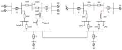
图1为500kV跨国交流互联电网系统示意图;Figure 1 is a schematic diagram of a 500kV transnational AC interconnected power grid system;
图2为电网联络线两端系统的连接示意图;FIG2 is a schematic diagram showing the connection of the systems at both ends of the grid tie line;
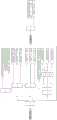
图3为故障跳闸判据的触发条件和动作条件示意图;FIG3 is a schematic diagram of the triggering conditions and action conditions of the fault tripping criterion;
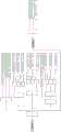
图4为故障跳闸判据的制定过程图;FIG4 is a diagram showing the process of formulating the fault tripping criterion;
图5为系统模拟单相瞬时故障下的波形图,其中,(5a)为电压的波形图,(5b)为电流的波形图,(5c)为有功功率的波形图;FIG5 is a waveform diagram of a system simulating a single-phase instantaneous fault, wherein (5a) is a waveform diagram of voltage, (5b) is a waveform diagram of current, and (5c) is a waveform diagram of active power;
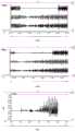
图6为系统模拟单相永久故障下的波形图,其中,(6a)为电压的波形图,(6b)为电流的波形图,(6c)为有功功率的波形图;FIG6 is a waveform diagram of a system simulating a single-phase permanent fault, wherein (6a) is a waveform diagram of voltage, (6b) is a waveform diagram of current, and (6c) is a waveform diagram of active power;
图7为系统模拟相间故障下的波形图,其中,(7a)为电压的波形图,(7b)为电流的波形图,(7c)为有功功率的波形图;FIG7 is a waveform diagram of a system simulating a phase-to-phase fault, wherein (7a) is a waveform diagram of voltage, (7b) is a waveform diagram of current, and (7c) is a waveform diagram of active power;
图8为系统模拟三相故障下的波形图,其中,(8a)为电压的波形图,(8b)为电流的波形图,(8c)为有功功率的波形图;FIG8 is a waveform diagram of a system simulating a three-phase fault, wherein (8a) is a waveform diagram of voltage, (8b) is a waveform diagram of current, and (8c) is a waveform diagram of active power;
图9为本发明中改进的安全稳定控制装置的单相瞬时故障跳闸判据的逻辑图;FIG9 is a logic diagram of the single-phase instantaneous fault tripping criterion of the improved safety and stability control device of the present invention;
图10为本发明中改进的安全稳定控制装置的单相永久故障跳闸判据的逻辑图;FIG10 is a logic diagram of a single-phase permanent fault tripping criterion of an improved safety and stability control device in the present invention;
图11为本发明中改进的安全稳定控制装置的相间故障跳闸判据的逻辑图;FIG11 is a logic diagram of the phase-to-phase fault tripping criterion of the improved safety and stability control device of the present invention;
图12为本发明中改进的安全稳定控制装置的三相故障跳闸判据的逻辑图。FIG. 12 is a logic diagram of the three-phase fault tripping criterion of the improved safety and stability control device in the present invention.
具体实施方式DETAILED DESCRIPTION
下面结合附图对本发明作更进一步的说明。The present invention will be further described below in conjunction with the accompanying drawings.
本发明公开了一种适应交流电网的安全稳定控制装置故障跳闸判别方法,搭建具有不完备信息的跨国交流互联电网的PSCAD仿真模型,基于现有的安全稳定控制装置的线路故障跳闸判据,即DL 755-2001电力系统安全稳定导则,模拟出对应的跳闸故障状态,改进现有的跳闸故障判据,使其适用于跨国交流输电电力系统。其中,搭建仿真模型时必需的信息包括电压、电流和有功功率,非必需的信息包括相角和无功功率。The invention discloses a fault tripping discrimination method for a safety and stability control device adapted to an AC power grid, builds a PSCAD simulation model of a transnational AC interconnected power grid with incomplete information, simulates a corresponding tripping fault state based on the existing line fault tripping criterion of the safety and stability control device, i.e., DL 755-2001 power system safety and stability guideline, improves the existing tripping fault criterion, and makes it applicable to a transnational AC power transmission power system. Wherein, the necessary information when building the simulation model includes voltage, current and active power, and the non-necessary information includes phase angle and reactive power.
如图1所示是本发明的一种实施例中特定场景下的500kV跨国交流互联电网,该跨国交流输电系统电压等级为±500kV,传输容量为2500MW,联络线长度为100km。图1中,设置左侧为云南电网,G1、G21、G31为汽轮发电机,G1的电压为166.6kV,输出电流为10kA,G22、G32为水轮发电机,电压为83.3kV,输出电流为5kA;设置右侧为老挝电网,G4为汽轮发电机,G5、G6为水轮发电机,电压为83.3kV,输出电流为5kA。针对特定场景下的500kV跨国交流互联电网构建PSCAD仿真模型,用来模拟联络线上的四类跳闸故障:单相瞬时故障、单相永久故障、相间故障和三相短路故障,通过设置不同的故障来观测联络线上的电压、电流、有功功率的波形,采集不同故障跳闸状态下的交流输电线路上的电压值、电流值、有功功率、相角差和频率。As shown in Figure 1, a 500kV transnational AC interconnected power grid in a specific scenario in an embodiment of the present invention is shown. The voltage level of the transnational AC power transmission system is ±500kV, the transmission capacity is 2500MW, and the length of the interconnection line is 100km. In Figure 1, the left side is set as the Yunnan power grid, G1, G21, and G31 are steam turbine generators, the voltage of G1 is 166.6kV, the output current is 10kA, G22 and G32 are hydro-turbine generators, the voltage is 83.3kV, and the output current is 5kA; the right side is set as the Laos power grid, G4 is a steam turbine generator, G5 and G6 are hydro-turbine generators, the voltage is 83.3kV, and the output current is 5kA. A PSCAD simulation model is constructed for a 500kV transnational AC interconnected power grid in a specific scenario to simulate four types of tripping faults on the interconnection line: single-phase instantaneous fault, single-phase permanent fault, phase-to-phase fault and three-phase short-circuit fault. By setting different faults to observe the waveforms of voltage, current and active power on the interconnection line, the voltage, current, active power, phase angle difference and frequency on the AC transmission line under different fault tripping states are collected.
图5是单相瞬时故障仿真波形,设置联络线故障启动时间为2s,持续故障时间为200ms,短路相设置在A相。单相瞬时故障后联络线上的电压、电流、有功功率、频率见图5。在A相短路之前,三相电压、电流无变化,有功功率小幅震荡,频率维持在50Hz左右;在A相短路后的200ms内,即2s~2.20s时,故障相电压跳为0,非故障相电压瞬间降低至
图6是单相永久故障仿真波形。设置联络线故障启动时间为2s,持续故障时间为2s,短路相设置在A相。单相永久故障后联络线上的电压、电流、有功功率、频率见图6。故障相电压在故障发生后跳为0,故障结束后发生周期性失步振荡,非故障相电压瞬间下降1.5kV,非故障相电压在故障生成后发生衰减振荡至0,随后发生周期性失步振荡;故障相电流在故障发生期间升为2倍后衰减为0,故障结束后发生周期性失步振荡,非故障相电流在故障生成后发生衰减振荡至0,随后发生周期性失步振荡;在发生故障后,有功功率发生衰减振荡,衰减为0后发生失步振荡。Figure 6 is the simulation waveform of a single-phase permanent fault. The tie line fault start time is set to 2s, the fault duration is 2s, and the short-circuit phase is set to phase A. The voltage, current, active power, and frequency on the tie line after a single-phase permanent fault are shown in Figure 6. The fault phase voltage jumps to 0 after the fault occurs, and periodic out-of-step oscillation occurs after the fault ends. The non-fault phase voltage drops 1.5kV instantly, and the non-fault phase voltage attenuates and oscillates to 0 after the fault is generated, followed by periodic out-of-step oscillation; the fault phase current rises to 2 times during the fault and then decays to 0, and periodic out-of-step oscillation occurs after the fault ends. The non-fault phase current attenuates and oscillates to 0 after the fault is generated, and then periodic out-of-step oscillation occurs; after the fault occurs, the active power attenuates and oscillates, and out-of-step oscillation occurs after decaying to 0.
图7是相间故障仿真波形,设置联络线故障启动时间为2s,持续故障时间为200ms,短路相设置在A、B相。相间故障后联络线上的电压、电流、有功功率、频率见图7。故障前电压、电流没有变化。在发生A、B相间短路后,故障相电压跳为0,非故障相电压瞬间降为
图8是三相故障仿真波形,设置联络线故障启动时间为2s,持续故障时间为200ms,短路相设置在A、B、C相。三相故障联络线上的电压、电流、有功功率、频率见图8。在发生故障前各相电压、电流均无变化。发生三相故障后,在故障持续的200ms内,三相电压均跳为0,三相电流均升为2倍后衰减为0,有功功率逐渐减小为0;故障结束后,三相电压均发生失步振荡,周期约为150ms,三相电流也均发生失步振荡,周期约为150ms,有功功率也发生失步振荡。Figure 8 is a three-phase fault simulation waveform. The tie line fault start time is set to 2s, the fault duration is 200ms, and the short-circuit phase is set to phases A, B, and C. The voltage, current, active power, and frequency on the three-phase fault tie line are shown in Figure 8. Before the fault occurred, the voltage and current of each phase did not change. After the three-phase fault occurred, within 200ms of the fault duration, the three-phase voltages all jumped to 0, the three-phase currents all increased by 2 times and then decayed to 0, and the active power gradually decreased to 0; after the fault ended, the three-phase voltages all oscillated out of step with a period of about 150ms, the three-phase currents also oscillated out of step with a period of about 150ms, and the active power also oscillated out of step.
如图4所示,本发明制定故障跳闸判据的具体分析步骤如下:As shown in FIG4 , the specific analysis steps for formulating the fault tripping criterion of the present invention are as follows:
步骤一:制定故障跳闸判据的触发条件Step 1: Establish the triggering conditions for fault tripping criteria
触发条件反映了系统故障状态,一般由运行方式、故障元件和故障类型的单个或多个元素组成。如图3所示,运行方式包括正常方式和检修方式等,故障元件包括联络线、输电线路和母线等,在交流线路中,故障类型包括相间故障、单相永久故障和无故障跳闸等。触发条件中的突变量一般是针对有功功率、电流与联络线两端电压的相角差来判断,根据图5至图8的仿真模型的波形分析,如果发生|Pt-Pt-200ms|≥ΔPs,或者任意一相|it-it-200ms|≥ΔIs,或者依据稳控装置的失步解列判据得到Δθ<130°,即可以判断为突变量启动,其中,Pt表示当前有功功率值;Pt-200ms表示200ms前的有功功率值;ΔPs表示有功功率触发定值;it表示当前电流瞬时值;it-200ms表示200ms前电流瞬时值;ΔIs表示电流触发定值;Δθ表示线路两端母线电压的相角差。有功功率触发定值ΔPs和电流触发定值ΔIs依据现有的安全稳定控制导则设定。200ms仅是依据本实施例中的仿真模型设定,为了方便观测波形,在不同故障条件下可以设置不同的数值。The trigger condition reflects the system fault state, which is generally composed of one or more elements of operation mode, fault element and fault type. As shown in Figure 3, the operation mode includes normal mode and maintenance mode, the fault element includes tie line, transmission line and busbar, and in AC line, the fault type includes phase-to-phase fault, single-phase permanent fault and no-fault tripping. The mutation in the trigger condition is generally judged by the phase angle difference of active power, current and voltage at both ends of the tie line. According to the waveform analysis of the simulation model of Figures 5 to 8, if |Pt -Pt-200ms |≥ΔPs , or any phase |it-it-200ms |≥ΔIs , or Δθ<130° is obtained according to the out-of-step decoupling criterion of the stabilization device, it can be judged as a mutation start, wherePt represents the current active power value; Pt-200ms represents the active power value 200ms ago;ΔPs represents the active power trigger value;it represents the current current instantaneous value;it-200ms represents the current instantaneous value 200ms ago;ΔIs represents the current trigger value; Δθ represents the phase angle difference of the bus voltage at both ends of the line. The active power trigger valueΔPs and the current trigger valueΔIs are set according to the existing safety and stability control guidelines. 200ms is only set according to the simulation model in this embodiment. In order to facilitate the observation of waveforms, different values can be set under different fault conditions.
在本发明实施例中,以500kV正常状态运行为例,依据安全稳定控制导则,Ps取0.1,ΔIs取1,均为整定值;其他系统电压级别下,可依据安全稳定控制导则计算。In the embodiment of the present invention, taking 500kV normal operation as an example, according to the safety and stability control guidelines,Ps is taken as 0.1 andΔIs is taken as 1, both of which are set values; at other system voltage levels, it can be calculated according to the safety and stability control guidelines.
步骤二:制定故障跳闸判据的动作条件判断Step 2: Formulate the action condition judgment of fault tripping criterion
动作条件判断作为判断环节,一般由断面潮流、功率门槛等元素组成。这里针对交流输电线路故障跳闸分为单相瞬时故障、单相永久故障、相间故障和三相故障四种,依据仿真模型的波形,依次进行分析判别。As a judgment link, the action condition judgment is generally composed of elements such as section flow and power threshold. Here, the AC transmission line fault tripping is divided into four types: single-phase instantaneous fault, single-phase permanent fault, phase-to-phase fault and three-phase fault. According to the waveform of the simulation model, they are analyzed and judged in turn.
根据图5至图8的波形,可以初步归纳出动作条件判据:According to the waveforms in Figures 5 to 8, the action condition criteria can be preliminarily summarized as follows:
单相瞬时故障:Single-phase instantaneous fault:
1、仅有一相电流增加;1. Only one phase current increases;
2、仅有一相电压降低;2. Only one phase voltage is reduced;
3、有一相跳闸信号,并在15ms内查找不到其它相跳闸信号。3. There is a phase trip signal, and no other phase trip signals can be found within 15ms.
单相永久故障:Single-phase permanent fault:
1、至少有一相电流增加;1. At least one phase current increases;
2、至少有一相电压降低;2. At least one phase voltage is reduced;
3、有两相跳闸信号;3. There are two-phase tripping signals;
4、两相跳闸信号之间的时间差大于重合闸时间。4. The time difference between the two-phase tripping signals is greater than the reclosing time.
相间故障:Phase-to-phase fault:
1、至少有两相电流增加;1. At least two phases of current increase;
2、至少有两相电压降低;2. At least two phases of voltage are reduced;
3、有两相跳闸信号;3. There are two-phase tripping signals;
4、两相跳闸信号之间的时间差小于重合闸时间。4. The time difference between the two-phase tripping signals is less than the reclosing time.
三相故障:Three-phase fault:
1、发生三相跳闸信号或者三相断路器位置接点变化;1. A three-phase trip signal occurs or the position contact of the three-phase circuit breaker changes;
2、三相电压均降低;2. All three-phase voltages are reduced;
3、三相电流均增加。3. All three-phase currents increase.
步骤三:制定控制措施Step 3: Develop control measures
控制措施作为执行环节,一般由切机、速降直流等元素组成。可以根据动作条件,分配各元素之间的逻辑关系与公式,然后针对各个对象(电压、电流、有功功率、相角差等)制定出适用于跨国交流输电电力系统联络线上的跳闸故障判据。制定的跳闸故障判据如图9至图12所示,具体如下:As the execution link, the control measures are generally composed of elements such as cutting the machine and reducing the DC. According to the action conditions, the logical relationship and formula between the elements can be allocated, and then the trip fault criterion applicable to the interconnection line of the cross-border AC transmission power system can be formulated for each object (voltage, current, active power, phase angle difference, etc.). The formulated trip fault criterion is shown in Figures 9 to 12, and is as follows:
单相瞬时故障,如图9所示,满足:Single-phase instantaneous fault, as shown in Figure 9, satisfies:
1、突变量启动;1. Mutation quantity starts;
2、仅有一相电流增加,对于该相电流,存在It-I-200ms≥In,其中,It为当前电流有效值,I200ms为突变量启动前200ms电流有效值,In为电流突变定值,在本实施例中500kV的系统电压级别下优选In=100A,在其他的系统电压级别下,可按比例计算;2. Only one phase current increases. For this phase current, It-I -200ms≥In exists, whereIt is the current effective value, I200ms is the effective value of the current 200ms before the sudden change is started, andIn is the current sudden change constant value. In this embodiment,In = 100A is preferred at a system voltage level of 500kV. At other system voltage levels, it can be calculated proportionally;
3、仅有一相电压降低,对于该相电压,存在U-200ms-Ut≥20%Un,其中,Ut为当前电压有效值,U-200ms为突变量启动前200ms电压有效值,20%Un为电压突变定值,Un为额定电压,在本发明实施例中500kV的系统电压级别下,Un=500kV;3. Only one phase voltage decreases. For this phase voltage, U-200ms -Ut ≥ 20%Un , where Ut is the current voltage effective value, U-200ms is the voltage effective value 200ms before the sudden change is started, 20%Un is the voltage sudden change fixed value, andUn is the rated voltage. In the embodiment of the present invention, at the system voltage level of 500kV,Un = 500kV;
4、仅有一相跳闸信号,并在15ms内查找不到其它相跳闸信号;4. There is only one phase trip signal, and no other phase trip signals can be found within 15ms;
5、基于联络线两端电压相角差和频差的复合判据:5. Composite criterion based on voltage phase angle difference and frequency difference at both ends of the tie line:
联络线两端电压相角差在0°-360°连续变化;The voltage phase angle difference at both ends of the tie line changes continuously from 0° to 360°;
或者联络线两端频差的绝对值|Δωt|≤0.1;Or the absolute value of the frequency difference between the two ends of the tie line |Δωt |≤0.1;
或者联络线两端频差极大值的绝对值|Δωt|max>Δωset,其中,Δωset为联络线两端频差阈值,等于正常运行情况下联络线首端频率减去末端频率,可以根据实际电网的特性分析、统计数据、实际运行经验进行具体整定,在本发明实施例中通过大量的仿真验证将频差阈值Δωset定为0.1(标幺值,基准值为50Hz),表明失步振荡过程中联络线两端频差至少为5Hz。Or the absolute value of the maximum frequency difference between the two ends of the tie line |Δωt |max >Δωset , where Δωset is the frequency difference threshold between the two ends of the tie line, which is equal to the frequency at the first end of the tie line minus the terminal frequency under normal operation. It can be specifically set according to the characteristic analysis, statistical data, and actual operation experience of the actual power grid. In the embodiment of the present invention, the frequency difference threshold Δωset is set to 0.1 (per-unit value, the reference value is 50 Hz) through a large number of simulation verifications, indicating that the frequency difference between the two ends of the tie line during the out-of-step oscillation process is at least 5 Hz.
单相永久故障,如图10所示,满足:Single-phase permanent fault, as shown in Figure 10, satisfies:
1、突变量启动;1. Mutation quantity starts;
2、至少有一相电流增加,对于该相电流,存在It-I-200ms≥In,其中,It为当前电流有效值,I200ms为突变量启动前200ms电流有效值,In为电流突变定值,在本实施例中500kV的系统电压级别下优选In=100A,在其他的系统电压级别下,可按比例计算;2. At least one phase current increases. For this phase current, It-I -200ms≥In exists, whereIt is the current effective value, I200ms is the effective value of the current 200ms before the sudden change is started, andIn is the current sudden change constant value. In this embodiment,In = 100A is preferred at a system voltage level of 500kV. At other system voltage levels, it can be calculated proportionally;
3、至少有一相电压降低,对于该相电压,存在U-200ms-Ut≥20%Un,其中,Ut为当前电压有效值,U-200ms为突变量启动前200ms电压有效值,20%Un为电压突变定值,Un为额定电压,在本实施例中500kV的系统电压级别下,Un=500kV;3. At least one phase voltage is reduced. For this phase voltage, U-200ms -Ut ≥ 20%Un , where Ut is the current voltage effective value, U-200ms is the voltage effective value 200ms before the sudden change is started, 20%Un is the voltage sudden change fixed value, andUn is the rated voltage. In this embodiment, at the system voltage level of 500kV,Un = 500kV;
4、有两相跳闸信号;4. There are two-phase tripping signals;
5、两相跳闸信号之间的时间差大于或等于重合闸时间,即t2-t1≥Tchz,其中,t2为第2相跳闸输入时刻,t1为第1相跳闸输入时刻,Tchz为重合闸时间,重合闸时间为固定时间,一般选取0.2s到0.5s;5. The time difference between the two-phase tripping signals is greater than or equal to the reclosing time, that is, t2 -t1 ≥Tchz , where t2 is the second phase tripping input time, t1 is the first phase tripping input time, and Tchz is the reclosing time. The reclosing time is a fixed time, generally selected from 0.2s to 0.5s;
6、基于联络线两端电压相角差和频差的复合判据:6. Composite criterion based on voltage phase difference and frequency difference at both ends of the tie line:
联络线两端电压相角差在0°-360°连续变化;The voltage phase angle difference at both ends of the tie line changes continuously from 0° to 360°;
或者联络线两端频差的绝对值|Δωt|≤0.1;Or the absolute value of the frequency difference between the two ends of the tie line |Δωt |≤0.1;
或者联络线两端频差极大值的绝对值|Δωt|max>Δωset,其中,Δωset为联络线两端频差阈值,等于正常运行情况下联络线首端频率减去末端频率,可以根据实际电网的特性分析、统计数据、实际运行经验进行具体整定,在本发明实施例中通过大量的仿真验证将频差阈值Δωset定为0.1(标幺值,基准值为50Hz),表明失步振荡过程中联络线两端频差至少为5Hz。Or the absolute value of the maximum frequency difference between the two ends of the tie line |Δωt |max >Δωset , where Δωset is the frequency difference threshold between the two ends of the tie line, which is equal to the frequency at the first end of the tie line minus the terminal frequency under normal operation. It can be specifically set according to the characteristic analysis, statistical data, and actual operation experience of the actual power grid. In the embodiment of the present invention, the frequency difference threshold Δωset is set to 0.1 (per-unit value, the reference value is 50 Hz) through a large number of simulation verifications, indicating that the frequency difference between the two ends of the tie line during the out-of-step oscillation process is at least 5 Hz.
相间故障,如图11所示,满足:Phase-to-phase fault, as shown in Figure 11, satisfies:
1、突变量启动;1. Mutation quantity starts;
2、至少有两相电流增加,对于该相电流,存在It-I-200ms≥In,其中,It为当前电流有效值,I200ms为突变量启动前200ms电流有效值,In为电流突变定值,在本实施例中500kV的系统电压级别下优选In=100A,在其他的系统电压级别下,可按比例计算;2. At least two phase currents increase. For the phase currents, It-I -200ms≥In exists, whereIt is the current effective value, I200ms is the effective value of the current 200ms before the sudden change is started, andIn is the current sudden change constant value. In this embodiment,In = 100A is preferred at a system voltage level of 500kV. At other system voltage levels, it can be calculated proportionally;
3、至少有两相电压降低,对于该相电压,存在U-200ms-Ut≥20%Un,其中,Ut为当前电压有效值,U-200ms为突变量启动前200ms电压有效值,20%Un为电压突变定值,Un为额定电压,在本实施例中500kV的系统电压级别下,Un=500kV;3. At least two phases have voltage reductions. For the phase voltages, U-200ms -Ut ≥ 20%Un , where Ut is the current voltage effective value, U-200ms is the voltage effective value 200ms before the sudden change is started, 20%Un is the voltage sudden change fixed value, andUn is the rated voltage. In this embodiment, at a system voltage level of 500kV,Un = 500kV;
4、有两相跳闸信号;4. There are two-phase tripping signals;
5、两相跳闸信号之间的时间差小于重合闸时间,即t2-t1<Tchz,其中,t2为第2相跳闸输入时刻,t1为第1相跳闸输入时刻,Tchz为重合闸时间,重合闸时间为固定时间,一般选取0.2s到0.5s;5. The time difference between the two-phase tripping signals is less than the reclosing time, that is, t2 -t1 <Tchz , where t2 is the second phase tripping input time, t1 is the first phase tripping input time, and Tchz is the reclosing time. The reclosing time is a fixed time, generally selected from 0.2s to 0.5s;
6、基于联络线两端电压相角差和频差的复合判据:6. Composite criterion based on voltage phase difference and frequency difference at both ends of the tie line:
联络线两端电压相角差在0°-360°连续变化;The voltage phase angle difference at both ends of the tie line changes continuously from 0° to 360°;
或者联络线两端频差的绝对值|Δωt|≤0.1;Or the absolute value of the frequency difference between the two ends of the tie line |Δωt |≤0.1;
或者联络线两端频差极大值的绝对值|Δωt|max>Δωset,其中,Δωset为联络线两端频差阈值,等于正常运行情况下联络线首端频率减去末端频率,可以根据实际电网的特性分析、统计数据、实际运行经验进行具体整定,在本发明实施例中通过大量的仿真验证将频差阈值Δωset定为0.1(标幺值,基准值为50Hz),表明失步振荡过程中联络线两端频差至少为5Hz。Or the absolute value of the maximum frequency difference between the two ends of the tie line |Δωt |max >Δωset , where Δωset is the frequency difference threshold between the two ends of the tie line, which is equal to the frequency at the first end of the tie line minus the terminal frequency under normal operation. It can be specifically set according to the characteristic analysis, statistical data, and actual operation experience of the actual power grid. In the embodiment of the present invention, the frequency difference threshold Δωset is set to 0.1 (per-unit value, the reference value is 50 Hz) through a large number of simulation verifications, indicating that the frequency difference between the two ends of the tie line during the out-of-step oscillation process is at least 5 Hz.
三相故障,如图12所示,满足:The three-phase fault, as shown in Figure 12, satisfies:
1、突变量启动;1. Mutation quantity starts;
2、发生三相跳闸信号或者三相断路器位置接点变化;2. A three-phase trip signal occurs or the position contacts of the three-phase circuit breaker change;
3、三相电压均降低,对于每相电压,存在U-200ms-Ut≥20%Un,其中,Ut为当前电压有效值,U-200ms为突变量启动前200ms电压有效值,20%Un为电压突变定值,Un为额定电压,在本实施例中500kV的系统电压级别下,Un=500kV;3. The three-phase voltages are all reduced. For each phase voltage, U-200ms -Ut ≥ 20%Un , where Ut is the current voltage effective value, U-200ms is the voltage effective value 200ms before the sudden change is started, 20%Un is the voltage sudden change fixed value, andUn is the rated voltage. In this embodiment, at the system voltage level of 500kV,Un = 500kV;
4、三相电流均增加,对于每相电流,存在It-I-200ms≥In,其中,It为当前电流有效值,I200ms为突变量启动前200ms电流有效值,In为电流突变定值,在本实施例中500kV的系统电压级别下优选In=100A,在其他的系统电压级别下,可按比例计算;4. The three-phase currents all increase. For each phase current, there exists It-I -200ms ≥In , whereIt is the current effective value, I200ms is the effective value of the current 200ms before the sudden change is started, and In is the current sudden change constant value. In this embodiment, at the system voltage level of 500kV, In =100A is preferred. At other system voltage levels, it can be calculated proportionally;
5、基于联络线两端电压相角差和频差的复合判据:5. Composite criterion based on voltage phase angle difference and frequency difference at both ends of the tie line:
联络线两端电压相角差在0°-360°连续变化;The voltage phase angle difference at both ends of the tie line changes continuously from 0° to 360°;
或者联络线两端频差的绝对值|Δωt|≤0.1;Or the absolute value of the frequency difference between the two ends of the tie line |Δωt |≤0.1;
或者联络线两端频差极大值的绝对值|Δωt|max>Δωset,其中,Δωset为联络线两端频差阈值,等于正常运行情况下联络线首端频率减去末端频率,可以根据实际电网的特性分析、统计数据、实际运行经验进行具体整定,在本发明实施例中通过大量的仿真验证将频差阈值Δωset定为0.1(标幺值,基准值为50Hz),表明失步振荡过程中联络线两端频差至少为5Hz。Or the absolute value of the maximum frequency difference between the two ends of the tie line |Δωt |max >Δωset , where Δωset is the frequency difference threshold between the two ends of the tie line, which is equal to the frequency at the first end of the tie line minus the terminal frequency under normal operation. It can be specifically set according to the characteristic analysis, statistical data, and actual operation experience of the actual power grid. In the embodiment of the present invention, the frequency difference threshold Δωset is set to 0.1 (per-unit value, the reference value is 50 Hz) through a large number of simulation verifications, indicating that the frequency difference between the two ends of the tie line during the out-of-step oscillation process is at least 5 Hz.
研究发现基于联络线两端相角差的失步解列判据在失步周期较长时,其轨迹便于定位振荡中心并判断失步状态,当失步周期较短时,该判据需要多个周期进行整定;而基于联络线两端频差的失步解列判据对于振荡中心迁移具有良好的适用性,且失步周期较短对该判据的整定不存在影响。因此,本发明采用基于联络线两端电压相角差和频差的复合判据,结合各个判据的优点,可以有效区分同步故障、短路故障、失步振荡,不受失步周期的影响,不受振荡中心迁移的影响,可以准确定位振荡中心,快速判断失步状态并实施解列。其中,当联络线两端频差小于或等于0.1时,即可判断出此状态为失步振荡状态,采用电压相角差判据进行振荡中心定位;当两端母线频差大于0.1时,采用频差判据进行失步状态的判断。The study found that the out-of-step decoupling criterion based on the phase angle difference at both ends of the interconnection line is convenient for locating the oscillation center and judging the out-of-step state when the out-of-step period is long. When the out-of-step period is short, the criterion needs multiple periods for adjustment; while the out-of-step decoupling criterion based on the frequency difference at both ends of the interconnection line has good applicability for the migration of the oscillation center, and the short out-of-step period has no effect on the adjustment of the criterion. Therefore, the present invention adopts a composite criterion based on the voltage phase angle difference and frequency difference at both ends of the interconnection line, and combines the advantages of each criterion to effectively distinguish synchronous faults, short-circuit faults, and out-of-step oscillations. It is not affected by the out-of-step period and the migration of the oscillation center. It can accurately locate the oscillation center, quickly judge the out-of-step state and implement decoupling. Among them, when the frequency difference at both ends of the interconnection line is less than or equal to 0.1, it can be judged that this state is an out-of-step oscillation state, and the voltage phase angle difference criterion is used to locate the oscillation center; when the frequency difference of the busbars at both ends is greater than 0.1, the frequency difference criterion is used to judge the out-of-step state.
如图2所示,令联络线两端的系统为M和N,M端系统的电压幅值为EM,N端系统的电压幅值为EN,其中EM是EN的Ke倍,两系统间的等值功角差为δ,则当电网异步运行时,联络线上C点处电压幅值的表达式为:As shown in Figure 2, let the systems at both ends of the tie line be M and N, the voltage amplitude of the M-end system isEM , and the voltage amplitude of the N-end system isEN , whereEM isKe times that ofEN , and the equivalent power angle difference between the two systems is δ. When the power grid is asynchronously operated, the expression of the voltage amplitude at point C on the tie line is:

其中,
当电网失步运行时,联络线上各点电压与电流的频率不再是一个与工频差不多的常数,而是随着时间和空间的不同而改变;当频率发生变化时,系统感抗和容抗也会发生变化;同时由于电压、电流变化很大,元件的非线性也不容忽视。依据研究需要,可以认为在很短的时间内,失步振荡是一个相对稳定的过程,假设计算过程中各个系统的频率不变,令M端系统频率为ωM,N端系统频率为ωN,初始相角为零,则等值功角差可表示为:When the power grid is out of step, the frequency of the voltage and current at each point on the tie line is no longer a constant similar to the power frequency, but changes with time and space; when the frequency changes, the system inductive reactance and capacitive reactance will also change; at the same time, due to the large changes in voltage and current, the nonlinearity of the components cannot be ignored. According to the research needs, it can be considered that in a very short period of time, the out-of-step oscillation is a relatively stable process. Assuming that the frequency of each system remains unchanged during the calculation process, let the system frequency at the M end be ωM , the system frequency at the N end be ωN , and the initial phase angle be zero, then the equivalent power angle difference can be expressed as:
δ=(ωM-ωN)*tδ=(ωM -ωN )*t
结合上面两个公式可得:Combining the above two formulas, we can get:

可以看出:当电网异步运行时两侧系统频率差就是电压幅值包络线的频率,每个周期内,当等值功角差δ为0或2π时,电压幅值会达到最大值UCmax=EN|Ke(1-k)+k|;当等值功角差δ为π时,电压幅值会达到最小值UCmin=EN|Ke(1-k)-k|;由失步中心电压为零,即Ke(1-k)-k=0可知,失步中心的位置为
因此,近似的使用联络线两端频差表示失步中心出现的时间间隔,由于失步振荡是一个较快的过程,其频率较大,所以可以用联络线两端频差的大小进行失步状态的检测。Therefore, the frequency difference at both ends of the tie line is used to approximately represent the time interval of the out-of-step center. Since the out-of-step oscillation is a faster process with a larger frequency, the magnitude of the frequency difference at both ends of the tie line can be used to detect the out-of-step state.
以系统电压等级为500kV的交流互联电网为例,说明本发明所述的安全稳定控制装置故障跳闸判别方法的有效性。Taking an AC interconnected power grid with a system voltage level of 500 kV as an example, the effectiveness of the fault tripping judgment method of the safety and stability control device described in the present invention is explained.
1、单相瞬时故障,其中A相在2秒时刻发生短路故障,持续200ms1. Single-phase instantaneous fault, where phase A has a short circuit fault at 2 seconds and lasts for 200ms
表1为500kV的交流互联电网单相瞬时故障前后三相电流与电压的统计表;表2为500kV的交流互联电网单相瞬时故障后联络线两端的电压相角差与频差的统计表。Table 1 is a statistical table of three-phase current and voltage before and after a single-phase instantaneous fault in a 500kV AC interconnected power grid; Table 2 is a statistical table of voltage phase angle difference and frequency difference at both ends of the interconnecting line after a single-phase instantaneous fault in a 500kV AC interconnected power grid.
表1Table 1

表2Table 2
发生单相瞬时故障前后,存在|Pt-Pt-200ms|=14.5-(-38)≥ΔPs,满足突变量启动;Before and after the single-phase instantaneous fault occurs, |Pt -Pt-200ms |=14.5-(-38)≥ΔPs exists, which satisfies the sudden change startup;
对于三相电流,仅有A相电流满足It-I-200ms=1.021kA≥In=100A,满足仅有一相电流增加;For three-phase current, only the A-phase current satisfies It -I-200ms = 1.021kA ≥I n = 100A, which means that only one-phase current increases;
对于三相电压,仅有A相电压满足U-200ms-Ut=183.0028kV≥20%Un=100kV,满足仅有一相电压降低;For the three-phase voltage, only the A-phase voltage satisfies U-200ms -Ut =183.0028kV≥20%Un =100kV, which satisfies that only one phase voltage is reduced;
对于联络线两端的电压相角差与频差,有联络线两端频差极大值的绝对值|Δωt|max=0.12>Δωset=0.1,满足基于联络线两端电压相角差和频差的复合判据。For the voltage phase angle difference and frequency difference at both ends of the tie line, the absolute value of the maximum frequency difference at both ends of the tie line |Δωt |max =0.12>Δωset =0.1, which satisfies the composite criterion based on the voltage phase angle difference and frequency difference at both ends of the tie line.
2、单相永久故障,其中A相在2秒时刻发生短路故障,持续2s2. Single-phase permanent fault, where phase A has a short circuit fault at 2 seconds and lasts for 2 seconds
表3为500kV的交流互联电网单相永久故障前后三相电流与电压的统计表;表4为500kV的交流互联电网单相永久故障后联络线两端的电压相角差与频差的统计表;表5为500kV的交流互联电网单相永久故障后跳闸信号的时间统计表。Table 3 is a statistical table of three-phase current and voltage before and after a single-phase permanent fault in a 500kV AC interconnected power grid; Table 4 is a statistical table of voltage phase angle difference and frequency difference at both ends of the interconnecting line after a single-phase permanent fault in a 500kV AC interconnected power grid; Table 5 is a time statistical table of tripping signals after a single-phase permanent fault in a 500kV AC interconnected power grid.
表3Table 3

表4Table 4
表5Table 5
发生单相永久故障前后,存在|Pt-Pt-200ms|=15.2-(-42)≥ΔPs,满足突变量启动;Before and after the single-phase permanent fault occurs, |Pt -Pt-200ms |=15.2-(-42)≥ΔPs exists, which satisfies the sudden change startup;
对于三相电流,A相电流满足It-I-200ms=3.375kA≥In=100A,满足至少有一相电流增加;For three-phase current, the current of phase A satisfies It -I-200ms = 3.375kA ≥I n = 100A, and at least one phase current increases;
对于三相电压,A相电压满足U-200ms-Ut=215.992kV≥20%Un=100kV,满足至少有一相电压降低;For three-phase voltage, the voltage of phase A satisfies U-200ms -Ut = 215.992kV ≥ 20% Un = 100kV, and at least one phase voltage is reduced;
对于跳闸信号,两相跳闸信号之间的时间差t2-t1=0.07≥Tchz=0.05s,满足两相跳闸信号之间的时间差大于或等于重合闸时间;For the trip signal, the time difference between the two-phase trip signals is t2 -t1 =0.07≥Tchz =0.05s, satisfying that the time difference between the two-phase trip signals is greater than or equal to the reclosing time;
对于联络线两端的电压相角差与频差,有联络线两端频差极大值的绝对值|Δωt|max=0.117>Δωset=0.1,满足基于联络线两端电压相角差和频差的复合判据。For the voltage phase angle difference and frequency difference at both ends of the tie line, the absolute value of the maximum frequency difference at both ends of the tie line |Δωt |max =0.117>Δωset =0.1, which satisfies the composite criterion based on the voltage phase angle difference and frequency difference at both ends of the tie line.
3、相间故障,其中AB相发生相间故障3. Phase-to-phase fault, where phase-to-phase fault occurs in AB phase
表6为500kV的交流互联电网相间故障前后三相电流与电压的统计表;表7为500kV的交流互联电网相间故障后联络线两端的电压相角差与频差的统计表;表8为500kV的交流互联电网相间故障后跳闸信号的时间统计表。Table 6 is a statistical table of three-phase current and voltage before and after the phase-to-phase fault of the 500kV AC interconnected power grid; Table 7 is a statistical table of voltage phase angle difference and frequency difference at both ends of the interconnecting line after the phase-to-phase fault of the 500kV AC interconnected power grid; Table 8 is a time statistical table of tripping signals after the phase-to-phase fault of the 500kV AC interconnected power grid.
表6Table 6

表7Table 7
表8Table 8
发生相间故障前后,存在|Pt-Pt-200ms|≥ΔPs,满足突变量启动;Before and after the phase-to-phase fault occurs, |Pt -Pt-200ms |≥ΔPs exists, which satisfies the sudden change startup;
对于三相电流,A相电流满足It-I-200ms=2.744kA≥In=100A,B相电流满足It-I-200ms=1.03kA≥In=100A,满足至少有两相电流增加;For the three-phase current, the A-phase current satisfies It- I-200ms = 2.744kA≥ I n = 100A, and the B-phase current satisfies It- I-200ms = 1.03kA ≥I n = 100A, which means that at least two phases have increased currents.
对于三相电压,A相电压满足U-200ms-Ut=200.8kV≥20%Un=100kV,B相电压满足U-200ms-Ut=226kV≥20%Un=100kV,满足至少有两相电压降低;For the three-phase voltage, the voltage of phase A satisfies U-200ms -Ut =200.8kV≥20%Un =100kV, and the voltage of phase B satisfies U-200ms -Ut =226kV≥20%Un =100kV, which satisfies that at least two phases have voltage reduction;
对于跳闸信号,两相跳闸信号之间的时间差t2-t1=0<Tchz=2.25s,满足两相跳闸信号之间的时间差小于重合闸时间;For the tripping signal, the time difference between the two-phase tripping signals is t2 -t1 =0<Tchz =2.25s, which satisfies that the time difference between the two-phase tripping signals is less than the reclosing time;
对于联络线两端的电压相角差与频差,有联络线两端频差极大值的绝对值|Δωt|max=0.121>Δωset=0.1,满足基于联络线两端电压相角差和频差的复合判据。For the voltage phase angle difference and frequency difference at both ends of the tie line, the absolute value of the maximum frequency difference at both ends of the tie line |Δωt |max =0.121>Δωset =0.1, which satisfies the composite criterion based on the voltage phase angle difference and frequency difference at both ends of the tie line.
4、三相故障4. Three-phase fault
表9为500kV的交流互联电网三相故障前后三相电流与电压的统计表;表10为500kV的交流互联电网三相故障后联络线两端的电压相角差与频差的统计表。Table 9 is a statistical table of three-phase current and voltage before and after a three-phase fault in a 500kV AC interconnected power grid; Table 10 is a statistical table of voltage phase angle difference and frequency difference at both ends of the interconnecting line after a three-phase fault in a 500kV AC interconnected power grid.
表9Table 9

表10Table 10
发生三相故障前后,存在|Pt-Pt-200ms|≥ΔPs,满足突变量启动;Before and after the three-phase fault occurs, |Pt -Pt-200ms |≥ΔPs exists, which satisfies the sudden change startup;
对于三相电流,A相电流满足It-I-200ms=0.9993kA≥In=100A,B相电流满足It-I-200ms=1.2198kA≥In=100A,C相电流满足It-I-200ms=1.218kA≥In=100A,满足三相电流均增加;For the three-phase current, the A-phase current satisfies It- I-200ms = 0.9993kA ≥I n = 100A, the B-phase current satisfies It-I -200ms = 1.2198kA≥ I n = 100A, and the C-phase current satisfies It- I-200ms = 1.218kA ≥I n = 100A, satisfying that the three-phase currents all increase;
对于三相电压,A相电压满足U-200ms-Ut=224.1kV≥20%Un=100kV,B相电压满足U-200ms-Ut=195.5kV≥20%Un=100kV,C相电压满足U-200ms-Ut=206.8kV≥20%Un=100kV,满足三相电压均降低;For the three-phase voltage, the A-phase voltage satisfies U-200ms -Ut =224.1kV≥20%Un =100kV, the B-phase voltage satisfies U-200ms -Ut =195.5kV≥20%Un =100kV, and the C-phase voltage satisfies U-200ms -Ut =206.8kV≥20%Un =100kV, so that the three-phase voltages are all reduced;
对于联络线两端的电压相角差与频差,有联络线两端频差极大值的绝对值|Δωt|max=0.1189>Δωset=0.1,满足基于联络线两端电压相角差和频差的复合判据。For the voltage phase angle difference and frequency difference at both ends of the tie line, the absolute value of the maximum frequency difference at both ends of the tie line |Δωt |max =0.1189>Δωset =0.1, which satisfies the composite criterion based on the voltage phase angle difference and frequency difference at both ends of the tie line.
以上所述仅是本发明的优选实施方式,应当指出:对于本技术领域的普通技术人员来说,在不脱离本发明原理的前提下,还可以做出若干改进和润饰,这些改进和润饰也应视为本发明的保护范围。The above is only a preferred embodiment of the present invention. It should be pointed out that for ordinary technicians in this technical field, several improvements and modifications can be made without departing from the principle of the present invention. These improvements and modifications should also be regarded as the scope of protection of the present invention.
Claims (8)
Priority Applications (1)
| Application Number | Priority Date | Filing Date | Title |
|---|---|---|---|
| CN202010854327.0ACN111999583B (en) | 2020-08-24 | 2020-08-24 | Fault trip judging method of safety and stability control device suitable for alternating current power grid |
Applications Claiming Priority (1)
| Application Number | Priority Date | Filing Date | Title |
|---|---|---|---|
| CN202010854327.0ACN111999583B (en) | 2020-08-24 | 2020-08-24 | Fault trip judging method of safety and stability control device suitable for alternating current power grid |
Publications (2)
| Publication Number | Publication Date |
|---|---|
| CN111999583A CN111999583A (en) | 2020-11-27 |
| CN111999583Btrue CN111999583B (en) | 2023-03-28 |
Family
ID=73473108
Family Applications (1)
| Application Number | Title | Priority Date | Filing Date |
|---|---|---|---|
| CN202010854327.0AActiveCN111999583B (en) | 2020-08-24 | 2020-08-24 | Fault trip judging method of safety and stability control device suitable for alternating current power grid |
Country Status (1)
| Country | Link |
|---|---|
| CN (1) | CN111999583B (en) |
Families Citing this family (9)
| Publication number | Priority date | Publication date | Assignee | Title |
|---|---|---|---|---|
| CN113013927B (en)* | 2021-03-15 | 2024-12-03 | 华能南通燃机发电有限公司 | A three-phase reclosing control method and system for generator |
| CN113447760B (en)* | 2021-06-24 | 2022-11-29 | 积成电子股份有限公司 | Modeling method and system for composite fault element in full electromagnetic transient fault scanning |
| CN113640620B (en)* | 2021-08-25 | 2024-01-23 | 云南电网有限责任公司电力科学研究院 | Method for judging states of circuit and element after fault |
| CN113986647A (en)* | 2021-09-23 | 2022-01-28 | 通号城市轨道交通技术有限公司 | Equipment monitoring method and system |
| CN114295887B (en)* | 2021-12-22 | 2023-07-18 | 科德数控股份有限公司 | Power failure detection method |
| CN115117875B (en)* | 2022-06-09 | 2025-07-15 | 重庆大学 | Method for improving the reclosing success rate of weakly connected local power grids taking into account new energy sources |
| CN116404611B (en)* | 2023-06-07 | 2023-09-08 | 佳源科技股份有限公司 | Leakage current protection method and leakage current protection system for photovoltaic grid-connected circuit breaker |
| CN116760001B (en)* | 2023-08-21 | 2023-12-05 | 国网江西省电力有限公司电力科学研究院 | Distribution network phase fault isolation method and system based on rapid opening of magnetic switches |
| CN117595258B (en)* | 2023-12-12 | 2024-07-05 | 西安兴汇电力科技有限公司 | Method for improving automatic closing transfer safety of tie switch |
Citations (7)
| Publication number | Priority date | Publication date | Assignee | Title |
|---|---|---|---|---|
| JPH08154335A (en)* | 1994-11-28 | 1996-06-11 | Tokyo Electric Power Co Inc:The | Phase angle difference, frequency difference and frequency calculation method in digital protective relay |
| CN102570454A (en)* | 2012-01-10 | 2012-07-11 | 中国电力科学研究院 | Simulation collocation method for oscillation disconnection device of power system |
| CN105004959A (en)* | 2015-04-09 | 2015-10-28 | 南京南瑞集团公司 | Wind farm sending-out line inter-phase fault determination method adaptive to stability control device |
| CN109149757A (en)* | 2018-09-26 | 2019-01-04 | 国电南瑞科技股份有限公司 | A kind of automatic closing method suitable for distributed new power grid |
| CN109274078A (en)* | 2018-09-28 | 2019-01-25 | 国电南瑞科技股份有限公司 | Method, device and device for line fault stability control criterion of safety and stability control device |
| CN110601140A (en)* | 2019-06-03 | 2019-12-20 | 史栓保 | Differential protection device and algorithm of variable frequency motor |
| WO2020162937A1 (en)* | 2019-02-07 | 2020-08-13 | General Electric Company | Automated model validation system for electrical grid |
Family Cites Families (1)
| Publication number | Priority date | Publication date | Assignee | Title |
|---|---|---|---|---|
| US10739396B2 (en)* | 2016-10-03 | 2020-08-11 | General Electric Technology Gmbh | Enhanced disturbance management of a power grid system |
- 2020
- 2020-08-24CNCN202010854327.0Apatent/CN111999583B/enactiveActive
Patent Citations (7)
| Publication number | Priority date | Publication date | Assignee | Title |
|---|---|---|---|---|
| JPH08154335A (en)* | 1994-11-28 | 1996-06-11 | Tokyo Electric Power Co Inc:The | Phase angle difference, frequency difference and frequency calculation method in digital protective relay |
| CN102570454A (en)* | 2012-01-10 | 2012-07-11 | 中国电力科学研究院 | Simulation collocation method for oscillation disconnection device of power system |
| CN105004959A (en)* | 2015-04-09 | 2015-10-28 | 南京南瑞集团公司 | Wind farm sending-out line inter-phase fault determination method adaptive to stability control device |
| CN109149757A (en)* | 2018-09-26 | 2019-01-04 | 国电南瑞科技股份有限公司 | A kind of automatic closing method suitable for distributed new power grid |
| CN109274078A (en)* | 2018-09-28 | 2019-01-25 | 国电南瑞科技股份有限公司 | Method, device and device for line fault stability control criterion of safety and stability control device |
| WO2020162937A1 (en)* | 2019-02-07 | 2020-08-13 | General Electric Company | Automated model validation system for electrical grid |
| CN110601140A (en)* | 2019-06-03 | 2019-12-20 | 史栓保 | Differential protection device and algorithm of variable frequency motor |
Non-Patent Citations (2)
| Title |
|---|
| 大电网紧急控制系统实验验证评估体系;杨丽 等;《电气技术》;20161231(第06期);第56-61页* |
| 泰安电网安全稳定性分析及对策研究;李雅文;《中国优秀硕士学位论文全文数据库 工程科技II辑》;20190215(第02期);全文* |
Also Published As
| Publication number | Publication date |
|---|---|
| CN111999583A (en) | 2020-11-27 |
Similar Documents
| Publication | Publication Date | Title |
|---|---|---|
| CN111999583B (en) | Fault trip judging method of safety and stability control device suitable for alternating current power grid | |
| Zamani et al. | A communication-assisted protection strategy for inverter-based medium-voltage microgrids | |
| CN102231517B (en) | Method and system for determining and isolating power distribution network fault | |
| CN113484665B (en) | Fault point positioning method in single-phase earth fault | |
| Shi et al. | The comparison and analysis for loss of excitation protection schemes in generator protection | |
| WO2023060705A1 (en) | Bus/line grounding line selection alternate removal method based on scada data | |
| CN103633630A (en) | Protection method for identifying fault braches based on zero-sequence active ratio | |
| CN104377642A (en) | Method for setting reclosing time on basis of secondary arc currents and recovery voltages | |
| CN102624090B (en) | Based on the intelligent high-pressure panel switches of electronic mutual inductor | |
| CN112421615A (en) | Power distribution station self-healing control method and system based on intelligent breaker action | |
| CN104578013A (en) | Directional protection method for distribution network comprising DFIG based on current frequency difference | |
| CN106786427A (en) | Based on the related wind power plant current collection line current guard method of waveform | |
| CN103354354A (en) | Impedance protection method and apparatus suitable for micro-electrical network | |
| Nayak et al. | Detecting fault during power swing for a series compensated line | |
| CN106684822A (en) | Transformer dead-zone fault protection method and breaker failure protection method | |
| CN112731211A (en) | Grounding transformer low-voltage winding turn-to-turn short circuit fault and phase identification method | |
| CN114123136B (en) | Protection method for power distribution network under distributed energy condition | |
| CN206977038U (en) | A kind of route protection measure and control device of integrated earthing wire-selecting function | |
| CN105375447A (en) | A three-phase reclosing time sequence setting method for reducing distance protection misoperation rate in alternating current and direct current systems | |
| Zin et al. | Effect of 132kV cross-country fault on distance protection system | |
| CN108241105A (en) | A test method of arc light grounding line selection device based on RTDS | |
| Kumar et al. | Fault detection in a series compensated line during power swing using superimposed apparent power | |
| CN115144700B (en) | New energy grid-connected system fault protection method based on injection signal amplitude | |
| CN107328981B (en) | Method for analyzing fault voltage of neutral point of transformer | |
| Xu et al. | Research on current transfer arc-extinguishing technology of distribution network |
Legal Events
| Date | Code | Title | Description |
|---|---|---|---|
| PB01 | Publication | ||
| PB01 | Publication | ||
| SE01 | Entry into force of request for substantive examination | ||
| SE01 | Entry into force of request for substantive examination | ||
| CB03 | Change of inventor or designer information | ||
| CB03 | Change of inventor or designer information | Inventor after:Li Xianyun Inventor after:Tang Li Inventor after:Wang Shuzheng Inventor after:Xie Chenxi Inventor before:Tang Li Inventor before:Li Xianyun Inventor before:Wang Shuzheng Inventor before:Xie Chenxi | |
| GR01 | Patent grant | ||
| GR01 | Patent grant |