CN111989542B - Spirit level having removable end cap with wall catch - Google Patents
Spirit level having removable end cap with wall catchDownload PDFInfo
- Publication number
- CN111989542B CN111989542BCN201980026408.7ACN201980026408ACN111989542BCN 111989542 BCN111989542 BCN 111989542BCN 201980026408 ACN201980026408 ACN 201980026408ACN 111989542 BCN111989542 BCN 111989542B
- Authority
- CN
- China
- Prior art keywords
- wall
- frame
- protrusion
- level
- aperture
- Prior art date
- Legal status (The legal status is an assumption and is not a legal conclusion. Google has not performed a legal analysis and makes no representation as to the accuracy of the status listed.)
- Active
Links
Images


Classifications
- G—PHYSICS
- G01—MEASURING; TESTING
- G01C—MEASURING DISTANCES, LEVELS OR BEARINGS; SURVEYING; NAVIGATION; GYROSCOPIC INSTRUMENTS; PHOTOGRAMMETRY OR VIDEOGRAMMETRY
- G01C9/00—Measuring inclination, e.g. by clinometers, by levels
- G01C9/02—Details
- G—PHYSICS
- G01—MEASURING; TESTING
- G01C—MEASURING DISTANCES, LEVELS OR BEARINGS; SURVEYING; NAVIGATION; GYROSCOPIC INSTRUMENTS; PHOTOGRAMMETRY OR VIDEOGRAMMETRY
- G01C9/00—Measuring inclination, e.g. by clinometers, by levels
- G01C9/18—Measuring inclination, e.g. by clinometers, by levels by using liquids
- G01C9/24—Measuring inclination, e.g. by clinometers, by levels by using liquids in closed containers partially filled with liquid so as to leave a gas bubble
- G01C9/26—Details
- G01C9/28—Mountings
- G—PHYSICS
- G01—MEASURING; TESTING
- G01C—MEASURING DISTANCES, LEVELS OR BEARINGS; SURVEYING; NAVIGATION; GYROSCOPIC INSTRUMENTS; PHOTOGRAMMETRY OR VIDEOGRAMMETRY
- G01C9/00—Measuring inclination, e.g. by clinometers, by levels
- G01C9/18—Measuring inclination, e.g. by clinometers, by levels by using liquids
- G01C9/24—Measuring inclination, e.g. by clinometers, by levels by using liquids in closed containers partially filled with liquid so as to leave a gas bubble
- G01C9/34—Measuring inclination, e.g. by clinometers, by levels by using liquids in closed containers partially filled with liquid so as to leave a gas bubble of the tubular type, i.e. for indicating the level in one direction only
Landscapes
- Physics & Mathematics (AREA)
- Engineering & Computer Science (AREA)
- General Physics & Mathematics (AREA)
- Radar, Positioning & Navigation (AREA)
- Remote Sensing (AREA)
- Connection Of Plates (AREA)
- Clamps And Clips (AREA)
Abstract
Translated fromChinese
Description
Translated fromChinese相关申请的交叉引用CROSS-REFERENCE TO RELATED APPLICATIONS
本申请要求于2018年4月27日提交的美国临时申请No.62/663,538的权益和优先权,该美国临时申请的全部内容通过参引并入本文中。This application claims the benefit of and priority to US Provisional Application No. 62/663,538, filed April 27, 2018, the entire contents of which are incorporated herein by reference.
背景技术Background technique
本公开总体上涉及水平仪的领域。本公开具体地涉及具有可移除端盖的水平仪。The present disclosure generally relates to the field of spirit levels. The present disclosure particularly relates to spirit levels with removable end caps.
水平仪用于多种应用、尤其是在建筑和建造行业中。传统上,为了测量取向,水平仪使用包含有液体(例如乙醇)和小的气体(例如空气)气泡的一个或更多个指管(vial)。指管的壁是弓形的,使得当水平仪放置在足够水平或竖直的表面上时,空气气泡在指管中的至少一个指管的中心处或在指管中的至少一个指管的中心附近对准。Spirit levels are used in a variety of applications, especially in the building and construction industry. Traditionally, to measure orientation, spirit levels use one or more vias containing liquid (eg, ethanol) and small gas (eg, air) bubbles. The walls of the vials are arcuate so that when the spirit level is placed on a sufficiently horizontal or vertical surface, the air bubbles are at or near the center of at least one of the vials alignment.
发明内容SUMMARY OF THE INVENTION
本公开的一种实施方式涉及水平仪,该水平仪包括纵向轴线、框架、诸如酒精指管或加速度计之类的取向测量部件、以及夹持件。框架包括上壁、下壁、由下壁限定的平坦的基部表面、以及在上壁与下壁之间延伸的相反的两个侧壁。内部通道由上壁、下壁和侧壁的内部表面限定。框架在框架的一个端部附近限定孔。夹持件包括第一壁、第二壁、孔和突出部,第一壁具有在夹持件联接至框架时接近框架的端部的第一端部,所述孔限定在第一壁内。夹持件被接纳在通道内,并且突出部接合框架的孔。突出部从第一壁向外延伸。突出部定位成使得存在与水平仪的平坦的基部表面平行的至少一条线,所述至少一条线从孔穿过突出部延伸至第一壁的第一端部。One embodiment of the present disclosure relates to a spirit level that includes a longitudinal axis, a frame, an orientation measurement component such as a spirit vial or accelerometer, and a holder. The frame includes an upper wall, a lower wall, a flat base surface defined by the lower wall, and two opposing side walls extending between the upper and lower walls. The interior channel is defined by the interior surfaces of the upper, lower and side walls. The frame defines an aperture near one end of the frame. The clip includes a first wall, a second wall, a hole defined in the first wall, and a projection, the first wall having a first end proximate an end of the frame when the clip is coupled to the frame. The clip is received within the channel and the protrusion engages the aperture of the frame. A protrusion extends outwardly from the first wall. The protrusion is positioned such that there is at least one line parallel to the flat base surface of the level, the at least one line extending from the hole through the protrusion to the first end of the first wall.
在特定实施方式中,第一壁的孔具有高度(例如,沿着与平坦的基部表面垂直的轴线测量)。第一壁的突出部限定第二高度(例如,沿着与平坦的基部表面垂直的轴线测量)。突出部的高度大于孔的高度。突出部限定凹陷表面和凸起表面,凹陷表面和凸起表面两者从第一壁面向外,并且凸起表面比凹陷表面从第一壁突出得远。水平仪还包括外部构件和锁定构件。外部构件接纳在夹持件的第一壁与第二壁之间,并且外部构件包括可移动突部。锁定构件布置在外部构件内,并且使可移动突部偏置成接合夹持件的第一壁的孔。第二壁限定孔,并且外部构件包括与第二壁的孔接合的第二可移动突部。夹持件的第一壁和第二壁偏置成抵靠框架。夹持件包括在第一壁与第二壁之间延伸的端部壁。In certain embodiments, the aperture of the first wall has a height (eg, measured along an axis perpendicular to the flat base surface). The protrusion of the first wall defines a second height (eg, measured along an axis perpendicular to the flat base surface). The height of the protrusion is greater than the height of the hole. The protrusion defines a concave surface and a convex surface, both of which face outward from the first wall, and the convex surface protrudes farther from the first wall than the concave surface. The level also includes an outer member and a locking member. An outer member is received between the first and second walls of the clamp, and the outer member includes a movable tab. A locking member is disposed within the outer member and biases the movable tab into engagement with the aperture of the first wall of the clip. The second wall defines an aperture, and the outer member includes a second movable tab that engages the aperture of the second wall. The first and second walls of the clip are biased against the frame. The clip includes an end wall extending between the first wall and the second wall.
在另一实施方式中,水平仪包括纵向轴线、框架、取向测量部件和夹持件。框架在框架的端部处限定中空腔,并且框架包括上壁、下壁、由下壁限定的平坦的基部表面以及相反的第一侧壁和第二侧壁,第一侧壁和第二侧壁两者在上壁与下壁之间延伸。在框架的第一端部附近在第一侧壁内限定孔。夹持件包括第一壁、第二壁、限定在第一壁内的孔、以及突出部。突出部从第一壁向外延伸,接合第一侧壁的孔,并且突出部限定凸起表面,该凸起表面至少延伸至框架的第一侧壁的最外侧部表面。In another embodiment, a spirit level includes a longitudinal axis, a frame, an orientation measuring member and a holder. The frame defines a hollow cavity at ends of the frame, and the frame includes an upper wall, a lower wall, a flat base surface defined by the lower wall, and opposing first and second side walls, the first and second sides Both walls extend between the upper wall and the lower wall. A hole is defined in the first side wall near the first end of the frame. The clip includes a first wall, a second wall, an aperture defined in the first wall, and a protrusion. A protrusion extends outwardly from the first wall, engages the aperture of the first side wall, and defines a raised surface extending at least to an outermost surface of the first side wall of the frame.
在另一实施方式中,水平仪包括框架、取向测量部件和夹持件。框架包括上壁、下壁、纵向轴线、由下壁限定的平坦的基部表面、以及相反的第一侧壁和第二侧壁,第一侧壁和第二侧壁两者在上壁与下壁之间延伸。第一侧壁限定长形孔。取向测量部件由框架支撑。夹持件包括第一壁、第二壁、限定在第一壁内的孔、以及长形突出部。突出部从第一壁向外延伸并且接合第一侧壁的长形孔。In another embodiment, a spirit level includes a frame, an orientation measurement component and a holder. The frame includes an upper wall, a lower wall, a longitudinal axis, a flat base surface defined by the lower wall, and opposing first and second side walls, both in the upper and lower walls extending between the walls. The first sidewall defines an elongated hole. The orientation measurement part is supported by the frame. The clip includes a first wall, a second wall, an aperture defined in the first wall, and an elongated projection. A protrusion extends outward from the first wall and engages the elongated hole of the first side wall.
本公开的一种实施方式涉及具有可移除端盖的水平仪。端盖包括夹持件、外部构件和锁定构件。夹持件包括穿过水平仪框架壁中的开口被接纳的突出部、比如壁卡持部。One embodiment of the present disclosure relates to a spirit level with a removable end cap. The end cap includes a clip, an outer member, and a locking member. The clip includes a projection, such as a wall catch, that is received through an opening in the level frame wall.
本公开的一些实施方式涉及具有放置在水平仪框架的纵向端部中的可移除端盖的水平仪。夹持件通过壁卡持部联接至水平仪框架,壁卡持部穿过接近水平仪框架的端部的孔被接纳。夹持件包括端部壁以及从端部壁延伸的两个侧壁。端部壁和侧壁一起部分地限定夹持件的内部,端盖的其他部件放置在夹持件的内部内。壁卡持部从侧壁的外部表面延伸并且构造成减少水平仪与工件(例如,壁)之间的滑移。壁卡持部定尺寸成使得其最外侧向表面延伸超过水平仪框架或本体的最外侧向表面,使得壁卡持部限定最外表面,该最外表面在水平仪邻近于工件或壁放置时将接触工件或壁。Some embodiments of the present disclosure relate to spirit levels having removable end caps placed in longitudinal ends of a spirit level frame. The clip is coupled to the level frame by a wall catch that is received through an aperture near the end of the level frame. The clip includes an end wall and two side walls extending from the end wall. The end walls and side walls together partially define the interior of the clip into which the other components of the end cap are placed. The wall catch extends from the exterior surface of the side wall and is configured to reduce slippage between the level and the workpiece (eg, the wall). The wall catch is dimensioned such that its outermost lateral surface extends beyond the outermost lateral surface of the level frame or body such that the wall catch defines an outermost surface that will contact when the level is placed adjacent to the workpiece or wall workpiece or wall.
外部构件部件放置在夹持件的内部。外部构件通过可移动壁联接至夹持件,所述可移动壁具有从可移动壁的外部表面延伸的突出部。突出部穿过夹持件的侧壁中的孔被接纳。外部构件包括可移动壁部分地限定的内部腔。当将锁定构件设置在外部构件的内部腔内时,锁定构件防止可移动壁的突出部与夹持件的孔断开接合。The outer member components are placed inside the holder. The outer member is coupled to the clamp by a movable wall having protrusions extending from an outer surface of the movable wall. The protrusions are received through holes in the side walls of the clip. The outer member includes an interior cavity partially defined by the movable wall. When the locking member is disposed within the interior cavity of the outer member, the locking member prevents the protrusion of the movable wall from disengaging with the aperture of the clip.
附加的特征和优点将在以下详细描述中阐述,并且这些特征和优点从说明书部分地对于本领域技术人员将是容易明显的,或者通过实施如本发明的书面描述内容和权利要求书以及附图中所描述的实施方式而被认识。应当理解的是,前面的一般描述和下面的详细描述都是示例性的。Additional features and advantages will be set forth in the following detailed description, and which will in part be readily apparent to those skilled in the art from the specification, or by practice such as the written description and claims of the invention and the accompanying drawings. be recognized by the implementation described in . It is to be understood that both the foregoing general description and the following detailed description are exemplary.
包括有附图以提供进一步的理解,并且附图被结合在该说明书中并且构成该说明书的一部分。附图示出了一种或更多种实施方式,并且与说明书一起用来解释各种实施方式的原理和操作。The accompanying drawings are included to provide a further understanding, and are incorporated in and constitute a part of this specification. The drawings illustrate one or more embodiments, and together with the description serve to explain the principles and operation of the various embodiments.
附图说明Description of drawings
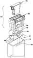
图1是根据实施方式的水平仪的立体图。FIG. 1 is a perspective view of a spirit level according to an embodiment.
图2是图1的根据示例性实施方式的水平仪的本体的横截面图。FIG. 2 is a cross-sectional view of the body of the spirit level of FIG. 1 according to an exemplary embodiment.
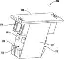
图3是根据实施方式的水平仪端盖的分解立体图。3 is an exploded perspective view of a level end cap according to an embodiment.
图4是根据示例性实施方式的端盖锁定构件的立体图。4 is a perspective view of an end cap locking member according to an exemplary embodiment.
图5是根据示例性实施方式的端盖外部构件的立体图。5 is a perspective view of an end cap outer member according to an exemplary embodiment.
图6是图5的根据示例性实施方式的端盖外部构件的立体截面图。FIG. 6 is a perspective cross-sectional view of the end cap outer member of FIG. 5 according to an exemplary embodiment.
图7是根据实施方式的水平仪端盖的分解立体图。7 is an exploded perspective view of a level end cap according to an embodiment.
具体实施方式Detailed ways
总体上参照附图,示出了水平仪的各种实施方式。本文所讨论的水平仪的各种实施方式包括创新的可移除端盖,该可移除端盖易于制造并且是抗震的,并且该可移除端盖包括壁卡持部结构,以当可移除端盖邻近于工件或壁放置时限制/防止水平仪滑动。Referring generally to the drawings, various embodiments of a spirit level are shown. Various embodiments of the spirit levels discussed herein include innovative removable end caps that are easy to manufacture and shock resistant, and that include wall catch structures for when removable Limit/prevent the level from sliding except when the end cap is placed adjacent to the workpiece or wall.
对于一些水平仪,水平仪框架或本体由金属材料形成,该金属材料已经形成为内部大部分为空的大体上中空的形状。盖放置在水平仪的任一端部以覆盖水平仪框架的端部处的开口。在本公开中描述的盖提供了有效的结构以牢固地封闭水平仪的端部。For some spirit levels, the spirit level frame or body is formed from a metallic material that has been formed into a generally hollow shape with a mostly hollow interior. Covers are placed on either end of the spirit level to cover the openings at the ends of the spirit level frame. The caps described in this disclosure provide an effective structure to securely close the ends of the spirit level.
在一种实施方式中,壁盖包括夹持件、放置在夹持件的内部内的外部构件和锁定构件。夹持件包括具有一个或更多个壁卡持部的侧壁,所述一个或更多个壁卡持部穿过水平仪的侧壁中的开口被接纳,以突出至卡持部可以与工作表面或壁接合的位置。在将夹持件放置在水平仪内时,夹持件侧壁远离彼此偏置。结果,在壁卡持部穿过水平仪框架孔被接纳之后,夹持件侧壁抵抗将壁卡持部从水平仪框架孔移除的尝试。In one embodiment, the wall cover includes a clip, an outer member placed within the interior of the clip, and a locking member. The clip includes a sidewall having one or more wall catches that are received through openings in the sidewall of the spirit level to protrude so that the catches can work with The location of the surface or wall joint. When the clamp is placed in the level, the clamp side walls are offset away from each other. As a result, after the wall catch is received through the level frame hole, the clip sidewall resists attempts to remove the wall catch from the level frame hole.
一旦夹持件紧固至水平仪的端部,则将外部构件放置在夹持件的内部内。外部构件包括具有突出部的可移动壁,该突出部穿过夹持件侧壁中的孔被接纳。在外部构件紧固至夹持件之后,将锁定构件放置在外部构件的内部内。当锁定构件插入到外部构件的内部中时,锁定构件推动可移动壁并且将可移动壁上的突出部固定至夹持件的孔。锁定构件包括拉拔部分,该拉拔部分提供用以移除锁定构件的卡持解除部(purchase)。Once the clamp is fastened to the end of the level, the outer member is placed within the interior of the clamp. The outer member includes a movable wall having a projection that is received through an aperture in the side wall of the clip. After the outer member is fastened to the clip, the locking member is placed within the interior of the outer member. When the locking member is inserted into the interior of the outer member, the locking member pushes the movable wall and secures the protrusion on the movable wall to the hole of the clip. The locking member includes a pull-out portion that provides a purchase for removing the locking member.
参照图1至图2,示出了根据示例性实施方式的水平仪、比如酒精水平仪100。通常,水平仪100包括框架102、第一手柄和第二手柄104、第一取向测量部件比如水平的酒精指管106、第二取向测量部件比如竖直或铅垂的酒精指管108、以及可移除端盖110。1-2, a spirit level, such as an
水平仪100包括位于水平仪100的顶部和底部上(从图1的角度来看)的沿着主轴线98从第一端部94延伸至第二端部96的测量表面112,测量表面112此处示出为上平坦表面112和下平坦表面112。水平仪100的测量表面112提供非常平坦的表面(例如,平的表面),非常平坦的表面允许水平仪100通过将水平仪100的测量表面中的一个测量表面放置成抵靠被测量的其他物体而测量物体的取向。考虑水平仪100可以具有任何数量的取向测量表面(例如,1至4个取向测量表面)。水平仪100在水平仪100的每个端部处包括示出为端盖110的端盖组件。端盖110布置成保护水平仪100的端部并且是可移除的。The
在所示的实施方式中,如图2所示,水平仪100是箱式水平仪,其中,框架102是大致箱形的。水平仪框架102包括上壁310、下壁312以及相反的侧壁314。顶部测量表面和底部测量表面112分别外围地位于上壁310和下壁312的外部。这些壁的内部表面316限定了示出为通道的框架内部302。框架102包括沿着内部表面316延伸并且邻近于框架102的拐角布置的肋状突出部304。In the illustrated embodiment, as shown in FIG. 2, the
参照图3至图7,夹持件402将端盖110紧固至水平仪100的第一端部94或第二端部96中的一者。夹持件402的侧壁404远离彼此偏置,使得侧壁404需要朝向彼此推动以将夹持件402插入水平仪100的框架102中。当将夹持件402插入框架102中时,首先将夹持件402的端部壁412插入,随后将侧壁404插入。夹持件402经由壁卡持部414联接至框架102,该壁卡持部414穿过水平仪框架102的孔202被接纳。Referring to FIGS. 3-7 , the
壁卡持部414从侧壁404的外表面沿远离夹持件402的另一个侧壁404的方向突出。在各种实施方式中,壁卡持部414通过共模制或包覆模制而联接至侧壁。壁卡持部414包括背向夹持件侧壁404的表面,该表面包括两个凸起的卡持表面416以及位于凸起的卡持表面416之间的凹陷部418(在图3中最佳地示出)。凹陷部418的宽度与夹持件侧壁404中的孔406的直径大致相同。如果需要,可以采用除矩形以外的形状的壁卡持部414。夹持件402中的孔406位于壁卡持部414与夹持件端部壁412之间。在一种或更多种实施方式中,壁卡持部414是由减轻滑移的材料、比如橡胶和/或弹性体、比如TPE、硅树脂、TPV等制成的单件。在各种实施方式中,壁卡持部414通过共模制或包覆模制而联接至侧壁。The
参照图2,凸起的卡持表面416超过框架102的最外侧向表面318延伸了水平距离320。该距离320允许壁卡持部414与被测量的工件的表面接合。在替代实施方式中,距离320为0(零)或接近零,并且壁卡持部和最外侧向表面318共同与被测量的工件的表面接合。在图2中所示的实施方式中,壁卡持部414的凹陷表面418没有延伸超过最外侧向表面318(图2中最佳地示出),然而,还考虑壁卡持部414的凹陷表面418延伸超过最外侧向表面318。Referring to FIG. 2 , the raised
夹持件402安装在水平仪框架102中,其中,夹持件侧壁404沿着侧壁314的内部表面316伸延并且总体上平行于侧壁314的内部表面316。夹持件侧壁404朝向彼此变形,并且这有助于将夹持件402保持在框架102内。在各种实施方式中,粘合剂施加在夹持件侧壁404与内部表面316之间,以补充夹持件402与框架102之间的紧固力。
在一种实施方式中,外部构件206的可移动壁604构造成相对于第一端部610偏转,该第一端部610本身联接至外部构件206的顶部结构612。当外部构件206插入到夹持件402中时,可移动壁604上的示出为可移动突部的锁定按钮606压靠于夹持件侧壁404,因此使可移动壁604朝向彼此变形。当锁定按钮606与夹持件侧壁404中的夹持件孔406对准时,锁定按钮606穿过夹持件孔406被接纳。In one embodiment, the
可移动壁604的挠性允许锁定按钮606选择性地与夹持件孔406接合和断开接合。锁定构件208插入腔602中导致锁定构件208的阻挡部分504压靠于可移动壁604。由于锁定构件208放置在外部构件206的腔602内,限制了可移动壁604朝向彼此充分弯曲而使锁定按钮606与夹持件孔406断开接合。以这种方式,锁定构件208能够在外部构件206内在锁定位置与解锁位置之间移动,在锁定位置中,阻挡部分504防止锁定按钮606与夹持件侧壁404的孔406断开接合,在解锁位置中,端盖110最终能够从框架102移除。The flexibility of the
锁定构件208包括拉拔部分502和从拉拔部分502延伸的阻挡部分504。拉拔部分502布置成保持在外部构件206的外部,并且提供了用于使锁定构件208向解锁位置移动(即,使得锁定构件208从外部构件206的腔602部分地或完全地移除)的表面。一个或更多个接合凸部508、突部506以及导引构件510从外部构件206的侧向表面512延伸。突部506与外部构件206的锁定表面704接合,以将锁定构件208紧固在外部构件206的腔602中。导引构件510与外部构件206的导引槽702接合以在锁定构件208完全定位在外部构件206的腔602内时将锁定构件208安置在锁定位置中。The locking
如图5至图6中所示的,外部构件206是具有盖部分601的长形构件,该盖部分601在外部构件206安装在夹持件402中时保持在框架102的外部,并且远离盖部分601延伸的侧臂608布置成当侧臂608沿着水平仪框架102的上壁310和下壁312的内部表面定位时接合框架102的内部表面316。示出为第一可移动壁604的可移动部分包括示出为锁定按钮606的突出部,该突出部相对于可移动壁604固定,并且优选地与可移动壁604形成为一个件。第二可移动壁604(在图6中最佳地示出)定位成与第一可移动壁604相反,并且与第一可移动壁604大致相同。通常,可移动壁604通过间隙603与侧臂608分开。该分开允许侧臂608被锁定构件208向外推动以产生将端盖110紧固至水平仪框架102的联接。As shown in FIGS. 5-6 , the
外部构件206包括导引槽702,该导引槽702定位成并且定尺寸成接纳锁定构件208的导引构件510。外部构件206还限定示出为锁定表面704的协作表面,该协作表面操作成在端盖110移除时维持锁定构件208与外部构件206之间的连接。通常,锁定构件208包括与外部构件206的协作表面接合的止挡结构,使得当锁定构件处于锁定位置时阻止锁定构件从外部构件的完全移除(即,外部构件206和锁定构件208在端盖110从框架102移除时保持在一起)。The
在一种或更多种实施方式中,夹持件402包括位于框架102的端部114附近且接近框架102的端部114的端部422,也就是说,夹持件402的端部422和框架102的端部114分开得小于5英寸,或更具体地分开得小于3英寸,这两个距离都是沿着框架102的纵向轴线98测量的。壁卡持部414布置在侧壁404内的孔406之间,使得存在与纵向轴线98平行的相交线424,该相交线424从孔406穿过壁卡持部414延伸至夹持件402的端部422。侧壁404的孔406限定高度426,该高度426沿着与平坦的基部表面112垂直的轴线被测量,而壁卡持部414限定高度428,该高度428也沿着与平坦的基部表面112垂直的轴线被测量。框架102在基部表面112与上表面112之间限定与平坦的基部表面112垂直的高度116。在一种或更多种实施方式中,壁卡持部414的高度428为框架102的高度116的至少40%。In one or more embodiments, the
壁卡持部414限定凸起的表面416,该凸起的表面416比凹陷表面418从侧壁404突出得远。壁卡持部414还限定沿着纵向轴线98测量的长度430。The
在一种实施方式中,仅一个侧壁404包括孔406。在另一实施方式中,两个侧壁404都包括孔406。在一种实施方式中,仅一个侧壁404包括壁卡持部414。在另一实施方式中,两个侧壁404都包括壁卡持部414。In one embodiment, only one
在一种或更多种实施方式中,框架102的孔202是长形的并且壁卡持部414也是长形的,使得壁卡持部414在孔202内配合。框架102的孔202包括垂直于平坦的基部表面112的纵向轴线。类似地,壁卡持部414包括垂直于平坦的基部表面112的纵向轴线。概括地描述,壁卡持部414限定框架的高度116的至少30%的高度,并且更具体地,壁卡持部414限定框架的高度116的至少45%的高度。In one or more embodiments, the
应当理解的是,附图详细地示出了说明性实施方式,并且应当理解的是,本申请不限于说明书中阐述的或在附图中示出的细节或方法。还应当理解的是,术语仅出于描述的目的,而不应该被认为是限制性的。It is to be understood that the drawings show illustrative embodiments in detail and that it is to be understood that the application is not limited to the details or methodology set forth in the specification or illustrated in the drawings. It is also to be understood that the terminology is for the purpose of description only and should not be regarded as limiting.
鉴于该描述,本公开的各个方面的进一步改型和替代实施方式对于本领域技术人员将是明显的。因此,该描述应当被解释为仅是说明性的。在各种示例性实施方式中示出的构型和布置仅是说明性的。尽管在本公开中仅详细描述了一些实施方式,但是许多改型是可能的(例如,在各种元件的大小、尺寸、结构、形状和比例、参数值、安装布置结构、材料的使用、颜色、取向等方面的变型),而不会在实质上脱离本文中所描述的主题事物的新颖教示和优点。示出为一体形成的一些元件可以由多个部件或元件构造,可以颠倒或者以其他方式改变元件的位置,并且离散元件或位置的性质或数目可以改变或变化。根据替代实施方式,任何过程、逻辑算法或方法步骤的顺序或次序可以改变或重新排序。在不脱离本公开的范围的情况下还可以对各种示例性实施方式的设计、操作状况和布置结构进行其他替换、改型、改变以及省略。Further modifications and alternative implementations of the various aspects of the present disclosure will be apparent to those skilled in the art in view of this description. Accordingly, the description should be construed as illustrative only. The configurations and arrangements shown in the various exemplary embodiments are illustrative only. Although only some embodiments have been described in detail in this disclosure, many modifications are possible (eg, in the size, dimensions, configuration, shape and proportions of various elements, parameter values, mounting arrangements, use of materials, colors , orientation, etc.) without materially departing from the novel teachings and advantages of the subject matter described herein. Some elements shown as integrally formed may be constructed from multiple parts or elements, the positions of elements may be reversed or otherwise varied, and the nature or number of discrete elements or positions may be altered or varied. The order or sequence of any process, logic algorithm, or method steps may be varied or re-sequenced according to alternative embodiments. Other substitutions, modifications, changes and omissions may also be made in the design, operating conditions and arrangement of the various exemplary embodiments without departing from the scope of the present disclosure.
除非另有明确说明,否则决不意味着本文中阐述的任何方法被解释为要求其步骤以特定的顺序执行。因此,在方法权利要求实际上不叙述其步骤所遵循的顺序或者在权利要求或描述内容中没有另外具体阐述步骤被限制为特定顺序的情况下,决不意味着能够推断出任何特定的顺序。另外,如本文中所使用的,冠词“一”意在包括一个或更多个部件或元件,并且并不意在被解释为仅意味着一个。如本文中所使用的,刚性联接是指两个部件以使得所述部件当受到力作用时能够以固定的位置关系一起移动的方式相联接。Unless explicitly stated otherwise, it is in no way intended that any method set forth herein be construed as requiring that its steps be performed in a particular order. Thus, in the event that a method claim does not actually recite the order in which the steps are followed or that the steps are not limited to a specific order as otherwise specifically recited in the claims or description, it is in no way meant that any specific order can be inferred. Additionally, as used herein, the article "a" is intended to include one or more components or elements, and is not intended to be construed to mean only one. As used herein, rigidly coupled refers to two components that are coupled in a manner that enables the components to move together in a fixed positional relationship when subjected to a force.
本公开的各种实施方式涉及任何特征的任何组合,并且在本申请或将来的申请中可以要求保护特征的任何这种组合。上述说明性实施方式的任何说明性实施方式的任何特征、元件或部件可以单独使用,或者与上述说明性实施方式的任何说明性实施方式的任何特征、元件或部件结合使用。Various embodiments of the present disclosure relate to any combination of any features, and any such combination of features may be claimed in this or a future application. Any feature, element or component of any of the above illustrative embodiments may be used alone or in combination with any feature, element or component of any of the above illustrative embodiments.
Claims (20)
Priority Applications (1)
| Application Number | Priority Date | Filing Date | Title |
|---|---|---|---|
| CN202211167416.3ACN115615399A (en) | 2018-04-27 | 2019-04-25 | Level meter |
Applications Claiming Priority (3)
| Application Number | Priority Date | Filing Date | Title |
|---|---|---|---|
| US201862663538P | 2018-04-27 | 2018-04-27 | |
| US62/663,538 | 2018-04-27 | ||
| PCT/US2019/029157WO2019210076A1 (en) | 2018-04-27 | 2019-04-25 | Level with removable end cap with wall grip |
Related Child Applications (1)
| Application Number | Title | Priority Date | Filing Date |
|---|---|---|---|
| CN202211167416.3ADivisionCN115615399A (en) | 2018-04-27 | 2019-04-25 | Level meter |
Publications (2)
| Publication Number | Publication Date |
|---|---|
| CN111989542A CN111989542A (en) | 2020-11-24 |
| CN111989542Btrue CN111989542B (en) | 2022-10-25 |
Family
ID=68295466
Family Applications (2)
| Application Number | Title | Priority Date | Filing Date |
|---|---|---|---|
| CN201980026408.7AActiveCN111989542B (en) | 2018-04-27 | 2019-04-25 | Spirit level having removable end cap with wall catch |
| CN202211167416.3APendingCN115615399A (en) | 2018-04-27 | 2019-04-25 | Level meter |
Family Applications After (1)
| Application Number | Title | Priority Date | Filing Date |
|---|---|---|---|
| CN202211167416.3APendingCN115615399A (en) | 2018-04-27 | 2019-04-25 | Level meter |
Country Status (3)
| Country | Link |
|---|---|
| US (1) | US12163805B2 (en) |
| CN (2) | CN111989542B (en) |
| WO (1) | WO2019210076A1 (en) |
Families Citing this family (1)
| Publication number | Priority date | Publication date | Assignee | Title |
|---|---|---|---|---|
| WO2017222855A1 (en)* | 2016-06-24 | 2017-12-28 | Milwaukee Electric Tool Corporation | Level with metal frame supporting protective outer body |
Citations (6)
| Publication number | Priority date | Publication date | Assignee | Title |
|---|---|---|---|---|
| GB2407382A (en)* | 2003-10-22 | 2005-04-27 | Alec Thornton | Bubble level having extension portions |
| JP5092041B1 (en)* | 2011-06-09 | 2012-12-05 | 株式会社エビス | Level |
| CN203337137U (en)* | 2013-07-22 | 2013-12-11 | 深圳市中测计量检测技术有限公司 | Portable gradienter |
| CN204881612U (en)* | 2015-05-14 | 2015-12-16 | 浙江金华托派特工具有限公司 | Novel I shape level bar end cover structure |
| CN206161001U (en)* | 2016-11-21 | 2017-05-10 | 张文军 | Fixed knot of level bar end cover constructs |
| CN110088570A (en)* | 2016-12-21 | 2019-08-02 | 米沃奇电动工具公司 | spirit level with removable end cap |
Family Cites Families (151)
| Publication number | Priority date | Publication date | Assignee | Title |
|---|---|---|---|---|
| US232982A (en) | 1880-10-05 | Spirit-level | ||
| US675464A (en) | 1900-07-13 | 1901-06-04 | Edwin Carlson | Combination-square. |
| US730790A (en) | 1902-09-24 | 1903-06-09 | Naftaly Newman | Combination-tool. |
| US1033742A (en) | 1911-05-16 | 1912-07-23 | John Skates | Square. |
| US1145195A (en) | 1914-07-25 | 1915-07-06 | Francis J Heisler | Umbrella. |
| US2171971A (en) | 1937-12-07 | 1939-09-05 | Nat Silver Deposit Ware Co | Illuminated level |
| US2535791A (en) | 1947-05-31 | 1950-12-26 | Buckeye Plastic Corp | Level with magnetic securing means |
| US2695949A (en) | 1952-01-17 | 1954-11-30 | James L Cuningham | Illuminated spirit level |
| US2634509A (en) | 1952-03-26 | 1953-04-14 | Sinclair T Roberts | Spirit level |
| US2789363A (en) | 1953-07-06 | 1957-04-23 | George E Miley | Magnetic level |
| US2939947A (en) | 1958-10-13 | 1960-06-07 | Edward H Schultz | Utility pocket level |
| US3046672A (en) | 1959-01-19 | 1962-07-31 | Harry S Lace | Level |
| US3036791A (en) | 1960-02-10 | 1962-05-29 | Hal P Kibbey | Tape or chalk line with magnetic holder |
| US3116563A (en) | 1960-11-02 | 1964-01-07 | Gelbman Burton | Installation fixture |
| US3100937A (en) | 1961-08-08 | 1963-08-20 | Archie E Burch | Tape measure |
| US3110115A (en) | 1961-09-05 | 1963-11-12 | Richard T Hubbard | Spirit level |
| US3213545A (en) | 1961-12-21 | 1965-10-26 | Empire Level Mfg Corp | Level with magnetic working surface |
| US3180036A (en) | 1962-07-26 | 1965-04-27 | Sr James E Meeks | Galvanized bead setter |
| US3187437A (en) | 1962-10-11 | 1965-06-08 | Ellis Hampton | Combined measuring and scribing device |
| US3279080A (en) | 1964-06-08 | 1966-10-18 | Edmund J Stepshinski | Gang outlet template |
| US3832782A (en) | 1972-01-14 | 1974-09-03 | V Johnson | All-craft level |
| DE7233283U (en) | 1972-09-09 | 1973-02-08 | Contrachoc Gmbh | SPIRIT LEVEL |
| US3881259A (en) | 1973-08-07 | 1975-05-06 | Gerard Pigeon | Level Indicating device |
| GB1529608A (en) | 1973-10-11 | 1978-10-25 | Ullrich Stabila Messgeraete | Spirit level |
| US4099331A (en) | 1976-05-17 | 1978-07-11 | Peterson Wallace W | Plumb-rule |
| US4126944A (en) | 1977-12-08 | 1978-11-28 | Burkhart David H | Disposable switch plate and receptacle cover spirit level |
| US4338725A (en) | 1981-01-06 | 1982-07-13 | Martin Larry J | Pipe fitter's quick square |
| US4407075A (en) | 1981-12-03 | 1983-10-04 | Louis Rains | Illuminated spirit vial and level |
| US4463501A (en) | 1982-01-25 | 1984-08-07 | Empire Level Mfg. Corp. | Level construction and methods of constructing a level |
| US4546774A (en) | 1983-02-24 | 1985-10-15 | Haught Robert M | Leveling device for hemodynamic monitoring transducer assembly |
| DE3314509A1 (en) | 1983-04-21 | 1984-10-25 | Stabila-Messgeräte Gustav Ullrich GmbH & Co KG, 6747 Annweiler | Spirit level with a hollow box-shaped spirit level |
| US4589213A (en) | 1985-03-11 | 1986-05-20 | William Woodward | Conduit bending level |
| US4593475A (en) | 1985-04-15 | 1986-06-10 | Great Neck Saw Manufacturing, Inc. | Level with slotted magnet support |
| US4793069A (en) | 1987-06-15 | 1988-12-27 | Mcdowell Kenneth H | Device for installing electric outlet boxes |
| US4888880A (en) | 1989-01-10 | 1989-12-26 | Parker Michael A | Electrician's level |
| US5033199A (en) | 1989-10-11 | 1991-07-23 | The Stanley Works | Level vial holder assembly |
| DE9001732U1 (en) | 1990-02-14 | 1991-06-13 | Stabila-Messgeräte Gustav Ullrich GmbH & Co KG, 6747 Annweiler | Tape measure |
| US5119936A (en) | 1990-04-30 | 1992-06-09 | Johnson Level And Tool Mfg. Co., Inc. | Structure and method for protectively encasing a level |
| US5165650A (en) | 1990-12-17 | 1992-11-24 | Letizia Louis S | Picture anchoring apparatus |
| US5080317A (en) | 1990-12-17 | 1992-01-14 | Letizia Louis S | Picture anchoring assembly |
| US5188234A (en) | 1992-03-06 | 1993-02-23 | Dart Industries Inc. | Lunchbox with carrying pouch |
| US5199177A (en) | 1992-05-14 | 1993-04-06 | Stanley Tools, A Division Of The Stanley Works | Level |
| DE9300224U1 (en) | 1993-01-10 | 1993-03-18 | Stabila-Messgeräte Gustav Ullrich GmbH & Co KG, 6747 Annweiler | Spirit level |
| AT398846B (en) | 1993-05-19 | 1995-02-27 | Scheyer Dietmar Ing | LEVEL |
| US5388338A (en) | 1993-10-18 | 1995-02-14 | Majors; Kevin R. | Interlocking screed level |
| US5535523A (en) | 1994-11-16 | 1996-07-16 | Endris; Matthew K. | Carpenter's square |
| US5495673A (en) | 1994-12-08 | 1996-03-05 | Imperial Schrade Corp. | Knife with detachable support |
| US5505001A (en) | 1994-12-22 | 1996-04-09 | Schaver, Jr.; James | Switch level |
| IL112882A0 (en)* | 1995-03-05 | 1995-06-29 | Kapro Ind Ltd | Spirit level |
| US5749152A (en) | 1995-07-10 | 1998-05-12 | Goss; William A. | Spirit level vial construction |
| US5659967A (en) | 1995-07-14 | 1997-08-26 | Johnson Level & Tool Mfg. Co., Inc. | Line level |
| US5940978A (en) | 1995-08-10 | 1999-08-24 | Empire Level Mfg. Corp. | Builder's level with hand-grip feature |
| US5722477A (en) | 1995-10-31 | 1998-03-03 | The Children's Factory | Pipe connector assembly with internal locking mechanism |
| US5755037A (en) | 1996-03-18 | 1998-05-26 | Great Neck Saw Manufactures, Inc. | Level |
| US5784792A (en) | 1996-05-13 | 1998-07-28 | Smith; James A. | Hand-held laser level grade checking device |
| US5671856A (en) | 1996-05-28 | 1997-09-30 | Lisch; Scott | Universal stackable locking container |
| US6029360A (en) | 1996-11-13 | 2000-02-29 | Koch; Robert E. | Multi-angle pocket level |
| US6173507B1 (en) | 1997-03-06 | 2001-01-16 | Frank Catallo | Arrangement and operation of improved dryer between shrinkage compactors to control residual shrinkage of wet knitted web to below that produced by tumble drying |
| US6003234A (en) | 1997-03-10 | 1999-12-21 | Seibert; John R. | Receptacle level |
| US5813130A (en) | 1997-05-05 | 1998-09-29 | Macdowell; Robert P. | Electrical gem box leveling template |
| US6213672B1 (en) | 1997-10-21 | 2001-04-10 | George J. Varga | Telescoping pole & cleaning tool |
| EP0919786A1 (en) | 1997-12-01 | 1999-06-02 | Stabila-Messgeräte Gustav Ullrich GmbH & Co.KG | Spirit level |
| JP3571894B2 (en) | 1997-12-08 | 2004-09-29 | 株式会社エビス | Level |
| JP3162010B2 (en) | 1997-12-25 | 2001-04-25 | 株式会社エビス | Magnet mounting structure for level |
| US6070336A (en) | 1998-03-12 | 2000-06-06 | Rodgers; Ron D. | Framing tool |
| DE29814656U1 (en) | 1998-08-14 | 1999-12-23 | Stabila-Messgeräte Gustav Ullrich GmbH & Co KG, 76855 Annweiler | Spirit level |
| EP1126239B1 (en) | 2000-02-19 | 2006-07-12 | SOLA-Messwerkzeuge GmbH | Spirit level |
| FR2807511B1 (en) | 2000-04-06 | 2003-01-24 | Lacroix Soc E | LOCK FOR IGNITION PLUG LEVER |
| US6675490B1 (en) | 2000-06-28 | 2004-01-13 | The Stanley Works | Level |
| DE20011458U1 (en) | 2000-06-29 | 2000-09-14 | RECA NORM GmbH & Co KG, 74635 Kupferzell | Leveling instrument |
| GB2364950A (en) | 2000-07-26 | 2002-02-13 | Graham Francis Pimbley | Template for use in electrical switch or socket box installation |
| DE10050656C1 (en)* | 2000-10-13 | 2002-01-24 | Hilti Ag | Self-leveling optical display device, has suspension unit for freely-suspended measuring system carrier provided with flexible fixings with rotationally symmetrical flexure resistance |
| FR2819947B1 (en) | 2001-01-19 | 2004-12-10 | Eddy Juric | DEVICE FOR FACILITATING THE HORIZONTALITY OF ELECTRICAL CONNECTORS DURING INSTALLATION |
| US20020148126A1 (en) | 2001-02-27 | 2002-10-17 | Smith Ronald Dean | Slope master |
| US7278218B2 (en) | 2003-06-18 | 2007-10-09 | Irwin Industrial Tool Company | Laser line generating device with swivel base |
| DE20109656U1 (en) | 2001-06-11 | 2002-10-24 | Stabila-Messgeräte Gustav Ullrich GmbH & Co KG, 76855 Annweiler | spirit level |
| US6568095B2 (en) | 2001-07-03 | 2003-05-27 | David H. Snyder | Magnetic torpedo level |
| US6785977B1 (en) | 2001-09-25 | 2004-09-07 | Michael P. Crichton | Measuring and leveling device |
| US6732441B2 (en) | 2002-01-24 | 2004-05-11 | Dale J. Charay | Leveling tool |
| US6839973B1 (en) | 2002-02-15 | 2005-01-11 | Christopher Woodward | Multiple axis leveling device |
| DE20203233U1 (en) | 2002-03-01 | 2003-07-10 | Stabila-Meßgeräte Gustav Ullrich GmbH, 76855 Annweiler | spirit level |
| US6760975B1 (en) | 2002-10-01 | 2004-07-13 | Great Neck Saw Manufacturers, Inc. | Vial holding level |
| US6782628B2 (en) | 2002-11-27 | 2004-08-31 | Vincent Liao | Level having rotatable vial support device |
| US7028413B2 (en) | 2003-06-24 | 2006-04-18 | Filipescu Louis F | Level stamp |
| US20050005947A1 (en) | 2003-07-11 | 2005-01-13 | Schweitzer-Mauduit International, Inc. | Smoking articles having reduced carbon monoxide delivery |
| ATE395574T1 (en) | 2003-12-31 | 2008-05-15 | Kapro Ind Ltd | POCKET SPIRIT LEVEL |
| DE202004000780U1 (en) | 2004-01-19 | 2004-05-13 | Sola-Messwerkzeuge Gmbh | Dragonfly for a spirit level |
| AT414044B (en)* | 2004-01-28 | 2006-08-15 | Sola Messwerkzeuge Gmbh | SPIRIT LEVEL |
| US6818824B1 (en) | 2004-03-19 | 2004-11-16 | Cooper Wiring Devices, Inc. | Wiring device ganging tool |
| US20050223577A1 (en) | 2004-04-13 | 2005-10-13 | Dane Scarborough | Removable level end caps |
| US7073270B2 (en) | 2004-04-16 | 2006-07-11 | Empire Level Mfg. Corp. | Impact-absorbing end caps for levels |
| US7343692B2 (en) | 2004-06-17 | 2008-03-18 | Schuyler Gould | Wiring device/wallplate installation tool |
| US7117606B2 (en) | 2004-07-27 | 2006-10-10 | Brown David A | Pocket-sized leveling tool |
| US7162758B2 (en) | 2004-09-14 | 2007-01-16 | Skinner Lyle J | Multipurpose gripping tool |
| US7089676B2 (en) | 2004-11-23 | 2006-08-15 | Sigifredo Godinez | Attaching level |
| US7406773B2 (en) | 2004-12-23 | 2008-08-05 | Irwin Industrial Tool Company | Magnet assembly |
| US7152335B2 (en) | 2005-03-05 | 2006-12-26 | Nichols Michael P | Omnidirectional torpedo level having magnetic mounts and adjustable protractor |
| US7409772B1 (en) | 2005-04-22 | 2008-08-12 | Kc Holdings, Llc | Apparatus and methods for level and/or straight edge tools |
| US7204029B2 (en) | 2005-05-04 | 2007-04-17 | The Stanley Works | Level |
| CN2804798Y (en) | 2005-06-21 | 2006-08-09 | 吴东明 | Horizon measuring means with magnetic device |
| JP4275112B2 (en) | 2005-07-20 | 2009-06-10 | 株式会社エビス | Level |
| US7360316B2 (en) | 2005-08-31 | 2008-04-22 | Irwin Industrial Tool Company | Level |
| US7513055B2 (en) | 2005-11-16 | 2009-04-07 | Montgomery Matthew C | Slope Level |
| US7281335B2 (en) | 2005-11-18 | 2007-10-16 | Pedro Feliciano | Carpenter's level |
| DE202005018286U1 (en) | 2005-11-21 | 2007-03-29 | Stabila-Meßgeräte Gustav Ullrich GmbH | laser measuring device |
| GB2436432B (en) | 2006-03-23 | 2010-07-21 | Michael Keith Ching | Spirit level |
| US7472486B2 (en) | 2006-05-19 | 2009-01-06 | The Stanley Works | Level with vial and manufacturing method therefor |
| US7472487B2 (en) | 2006-05-26 | 2009-01-06 | The Stanley Works | Level |
| US7392594B2 (en) | 2006-07-28 | 2008-07-01 | Fred Kesler | Electrical device-mounting tool |
| US7484307B2 (en) | 2006-10-16 | 2009-02-03 | The Stanley Works | Level with uninterrupted marking surface with high-visibility center vial |
| US7530175B2 (en) | 2006-12-15 | 2009-05-12 | Black & Decker Inc. | Twin level |
| DE202007001753U1 (en) | 2006-12-29 | 2007-06-06 | STABILA Messgeräte Gustav Ullrich GmbH | Measuring device e.g. construction laser apparatus, has housing surrounded by cover that is pivoted around axis crossing housing, where cover has section that covers or uncovers radiation emission hole based on pivoting position of cover |
| US7748128B2 (en) | 2007-03-23 | 2010-07-06 | Steven Ross Martin | Slab doctor level |
| CA2681652C (en) | 2007-04-10 | 2015-03-31 | James S. Allemand | Level tool |
| CN101711344B (en) | 2007-05-04 | 2013-05-01 | 詹姆斯·S·阿利曼德 | Clamping level instrument tool |
| CA2685604A1 (en) | 2007-05-18 | 2008-11-27 | James S. Allemand | Composite level tool |
| US7536798B2 (en) | 2007-05-30 | 2009-05-26 | Precision Designed Products, Inc. | Multiple angle compact spirit level |
| US7520065B2 (en) | 2007-06-07 | 2009-04-21 | Bryan Vernola | Level with integral clamp for mounting conduit apparatus and method |
| US7467475B1 (en) | 2007-07-11 | 2008-12-23 | Cheek Attila G | Leveling device |
| US7513056B1 (en) | 2007-11-01 | 2009-04-07 | Black & Decker Inc. | Spirit level with sliding measurement system |
| US7669342B1 (en)* | 2007-12-07 | 2010-03-02 | Seco Manufacturing Company, Inc. | Level for a geomatics target device |
| US7827699B2 (en) | 2007-12-21 | 2010-11-09 | Montgomery Matthew C | Environmentally-friendly levels |
| CN101487701B (en) | 2008-01-19 | 2011-08-10 | 庄成荣 | Multifunctional vibration damping end cap for leveler |
| US7644506B2 (en) | 2008-02-14 | 2010-01-12 | Harry Wong | Edge level with side magnets and velcro(hook and loop fastener) |
| US8011108B2 (en) | 2008-04-04 | 2011-09-06 | Robert Upthegrove | Leveling device |
| US7770298B1 (en) | 2008-04-11 | 2010-08-10 | Johnson Level & Tool Mfg. Co., Inc. | Securement arrangement for a level end cap |
| CN201221945Y (en) | 2008-07-07 | 2009-04-15 | 南京德朔实业有限公司 | Horizontal rule |
| CN201221946Y (en) | 2008-07-07 | 2009-04-15 | 南京德朔实业有限公司 | Horizontal rule with shock resistance end cap |
| US8109005B2 (en) | 2008-07-11 | 2012-02-07 | Hudson Robert B | Dual-globe level |
| US20100095543A1 (en) | 2008-10-21 | 2010-04-22 | Santana Inthavong | Tool for Installing an Electrical Outlet Box |
| US7832112B2 (en) | 2008-11-10 | 2010-11-16 | Empire Level Mfg. Co. | Vial-mounting structure |
| US8011109B2 (en) | 2009-02-27 | 2011-09-06 | Empire Level Mfg. Corp. | Casing mount for a cylindrical vial |
| US8336221B2 (en) | 2009-10-27 | 2012-12-25 | Milwaukee Electric Tool Corporation | Level |
| WO2011059475A1 (en) | 2009-10-29 | 2011-05-19 | Empire Level Mfg. Co. | Box level |
| AU2011248348B2 (en) | 2010-05-03 | 2014-12-18 | Swanson Tool Company, Inc. | Lighted level tool |
| US8910390B2 (en) | 2010-10-26 | 2014-12-16 | Milwaukee Electric Tool Corporation | Level |
| US9546867B2 (en) | 2010-12-31 | 2017-01-17 | The Regular Guys, Llc | Multi-function level with a joinable end |
| US8677636B2 (en)* | 2011-02-11 | 2014-03-25 | Jentra Llc | Door installation tool and method |
| US8413342B2 (en) | 2011-03-03 | 2013-04-09 | Empire Level Mfg. Corp. | Level with a magnet-mounting structure |
| US8826554B2 (en) | 2011-03-29 | 2014-09-09 | Ronald Bariteau | Custom baluster level |
| US8850710B1 (en) | 2011-12-06 | 2014-10-07 | Timothy J. Rodrigue | Interconnectable construction level system |
| US9243907B2 (en) | 2012-06-20 | 2016-01-26 | Mark L Silberberg | Bubble level |
| US9021710B2 (en) | 2012-06-20 | 2015-05-05 | Mark L. Silberberg | Bubble level |
| US9234751B2 (en) | 2012-06-20 | 2016-01-12 | Mark L Silberberg | Bubble level |
| US9360315B2 (en) | 2013-06-24 | 2016-06-07 | Mark L. Silberberg | Bubble level |
| US9909870B2 (en)* | 2014-11-13 | 2018-03-06 | Milwaukee Electric Tool Corporation | Level including removable end caps |
| US9885572B2 (en) | 2014-11-13 | 2018-02-06 | Milwaukee Electric Tool Corporation | Level including a slot for receiving a straight edge |
| CN113607133B (en) | 2014-11-13 | 2024-08-23 | 米沃奇电动工具公司 | Level |
| US10591297B2 (en)* | 2016-10-05 | 2020-03-17 | Milwaukee Electric Tool Corporation | Level with removable and/or interchangeable sleeve |
| US10458791B2 (en) | 2017-08-16 | 2019-10-29 | Stanley & Black & Decker, Inc. | Level with quick-disconnect end cap |
| US11085762B2 (en)* | 2018-04-27 | 2021-08-10 | Milwaukee Electric Tool Corporation | Level with removable end cap with wall grip |
- 2019
- 2019-04-25CNCN201980026408.7Apatent/CN111989542B/enactiveActive
- 2019-04-25CNCN202211167416.3Apatent/CN115615399A/enactivePending
- 2019-04-25WOPCT/US2019/029157patent/WO2019210076A1/ennot_activeCeased
- 2023
- 2023-03-16USUS18/185,168patent/US12163805B2/enactiveActive
Patent Citations (6)
| Publication number | Priority date | Publication date | Assignee | Title |
|---|---|---|---|---|
| GB2407382A (en)* | 2003-10-22 | 2005-04-27 | Alec Thornton | Bubble level having extension portions |
| JP5092041B1 (en)* | 2011-06-09 | 2012-12-05 | 株式会社エビス | Level |
| CN203337137U (en)* | 2013-07-22 | 2013-12-11 | 深圳市中测计量检测技术有限公司 | Portable gradienter |
| CN204881612U (en)* | 2015-05-14 | 2015-12-16 | 浙江金华托派特工具有限公司 | Novel I shape level bar end cover structure |
| CN206161001U (en)* | 2016-11-21 | 2017-05-10 | 张文军 | Fixed knot of level bar end cover constructs |
| CN110088570A (en)* | 2016-12-21 | 2019-08-02 | 米沃奇电动工具公司 | spirit level with removable end cap |
Also Published As
| Publication number | Publication date |
|---|---|
| US12163805B2 (en) | 2024-12-10 |
| US20230221114A1 (en) | 2023-07-13 |
| WO2019210076A1 (en) | 2019-10-31 |
| CN111989542A (en) | 2020-11-24 |
| CN115615399A (en) | 2023-01-17 |
Similar Documents
| Publication | Publication Date | Title |
|---|---|---|
| US11441898B2 (en) | Level with removable end cap | |
| US11629956B2 (en) | Level with removable end cap with wall grip | |
| US11982543B2 (en) | Level with removable end cap | |
| US10849247B2 (en) | Vehicle-mounted electronic device including a substrate inside a housing | |
| JP2009545760A (en) | Device for holding the camera on a support | |
| JP2018071789A (en) | Pin and grommet fastener accommodating bidirectional offset and related method | |
| US11002610B2 (en) | Temperature detection module | |
| US20150180168A1 (en) | Connector Assembly | |
| TWI634062B (en) | Substrate storage container | |
| CN111989542B (en) | Spirit level having removable end cap with wall catch | |
| ES2974676T3 (en) | Fixing structure | |
| US8123545B1 (en) | Latch and extractor for electronic module | |
| TWI628126B (en) | Substrate storage container | |
| JP5346530B2 (en) | Holding frame for connector module | |
| US9741631B2 (en) | Substrate storage container with handling members | |
| KR101408669B1 (en) | Thin plate storage container | |
| CN222272691U (en) | Pipette tip box | |
| CN104244623A (en) | Electronic device shell | |
| JP2014095632A (en) | Level | |
| JP5827884B2 (en) | Glass holder | |
| US8690361B2 (en) | Case structure and optical device having such case structure | |
| JP2014095683A (en) | Spirit level | |
| TWI428510B (en) | Fixing apparatus for fan | |
| KR101526580B1 (en) | Camera module assembly | |
| JP6506618B2 (en) | Fire detector attachment |
Legal Events
| Date | Code | Title | Description |
|---|---|---|---|
| PB01 | Publication | ||
| PB01 | Publication | ||
| SE01 | Entry into force of request for substantive examination | ||
| SE01 | Entry into force of request for substantive examination | ||
| GR01 | Patent grant | ||
| GR01 | Patent grant |