CN111982028A - A laser radar scanning galvanometer three-dimensional angle measurement device and method - Google Patents
A laser radar scanning galvanometer three-dimensional angle measurement device and methodDownload PDFInfo
- Publication number
- CN111982028A CN111982028ACN202010716357.5ACN202010716357ACN111982028ACN 111982028 ACN111982028 ACN 111982028ACN 202010716357 ACN202010716357 ACN 202010716357ACN 111982028 ACN111982028 ACN 111982028A
- Authority
- CN
- China
- Prior art keywords
- laser
- scanning galvanometer
- spot
- positive
- zero
- Prior art date
- Legal status (The legal status is an assumption and is not a legal conclusion. Google has not performed a legal analysis and makes no representation as to the accuracy of the status listed.)
- Pending
Links
- 238000005259measurementMethods0.000titleclaimsabstractdescription32
- 238000000034methodMethods0.000titleclaimsabstractdescription16
- 238000001514detection methodMethods0.000claimsdescription15
- 230000008859changeEffects0.000claimsdescription6
- 230000007246mechanismEffects0.000claimsdescription4
- 230000003287optical effectEffects0.000claimsdescription3
- 238000006073displacement reactionMethods0.000abstractdescription13
- 238000010586diagramMethods0.000description8
- 230000008569processEffects0.000description6
- 238000000691measurement methodMethods0.000description3
- 238000009434installationMethods0.000description2
- 238000012545processingMethods0.000description2
- 230000009286beneficial effectEffects0.000description1
- 238000004891communicationMethods0.000description1
- 230000007613environmental effectEffects0.000description1
- 238000003384imaging methodMethods0.000description1
- 238000012986modificationMethods0.000description1
- 230000004048modificationEffects0.000description1
- 230000010287polarizationEffects0.000description1
- 238000002366time-of-flight methodMethods0.000description1
Images


Classifications
- G—PHYSICS
- G01—MEASURING; TESTING
- G01B—MEASURING LENGTH, THICKNESS OR SIMILAR LINEAR DIMENSIONS; MEASURING ANGLES; MEASURING AREAS; MEASURING IRREGULARITIES OF SURFACES OR CONTOURS
- G01B11/00—Measuring arrangements characterised by the use of optical techniques
- G01B11/26—Measuring arrangements characterised by the use of optical techniques for measuring angles or tapers; for testing the alignment of axes
- G—PHYSICS
- G01—MEASURING; TESTING
- G01S—RADIO DIRECTION-FINDING; RADIO NAVIGATION; DETERMINING DISTANCE OR VELOCITY BY USE OF RADIO WAVES; LOCATING OR PRESENCE-DETECTING BY USE OF THE REFLECTION OR RERADIATION OF RADIO WAVES; ANALOGOUS ARRANGEMENTS USING OTHER WAVES
- G01S17/00—Systems using the reflection or reradiation of electromagnetic waves other than radio waves, e.g. lidar systems
- G01S17/02—Systems using the reflection of electromagnetic waves other than radio waves
- G01S17/06—Systems determining position data of a target
Landscapes
- Physics & Mathematics (AREA)
- Electromagnetism (AREA)
- Engineering & Computer Science (AREA)
- General Physics & Mathematics (AREA)
- Computer Networks & Wireless Communication (AREA)
- Radar, Positioning & Navigation (AREA)
- Remote Sensing (AREA)
- Length Measuring Devices By Optical Means (AREA)
Abstract
Translated fromChinese
Description
Translated fromChinese技术领域technical field
本发明涉及角度测量领域,具体涉及一种激光雷达扫描振镜三维角度测量装置和方法。The invention relates to the field of angle measurement, in particular to a three-dimensional angle measurement device and method of a laser radar scanning galvanometer.
背景技术Background technique
激光雷达是一种集探测目标、远程测距、面阵成像等功能于一体的激光传感系统,其具有比较高的距离和角度测量分辨率,比较大的测量范围和工作距离,以及优异的抗干扰能力。近年来,激光雷达的应用场景逐渐从军事用途转向民用领域,在资源勘探,交通通讯,环境检测等方面发挥越来越重要的作用。激光雷达系统主要由激光发射系统、振镜扫描系统、激光接收系统和信号处理系统组成,其中振镜扫描系统是激光雷达系统的重要组成部分,其决定了激光雷达的探测范围和角位置测量精度。Lidar is a laser sensing system that integrates the functions of target detection, long-range ranging, and area array imaging. It has relatively high distance and angle measurement resolution, relatively large measurement range and working distance, and excellent Anti-interference ability. In recent years, the application scenario of lidar has gradually shifted from military use to civilian use, and has played an increasingly important role in resource exploration, transportation and communication, and environmental detection. The lidar system is mainly composed of a laser transmitting system, a galvanometer scanning system, a laser receiving system and a signal processing system. The galvanometer scanning system is an important part of the lidar system, which determines the detection range and angular position measurement accuracy of the lidar. .
传统的振镜扫描系统包括反射镜和扫描振镜,扫描振镜由扫描电机和伺服电路组成。扫描电机内部集成了电容式角位置传感器,控制程序会根据待扫描物体的空间位置,发送指令给伺服电路,控制和驱动扫描电机将发射井旋转到相应的角位置。如上所述,振镜扫描系统的角位置精度决定了激光雷达的角度测量分辨率,因此在激光雷达工作过程中精确测量扫描振镜的角位置是十分必要的。The traditional galvanometer scanning system includes a mirror and a scanning galvanometer, and the scanning galvanometer is composed of a scanning motor and a servo circuit. The scanning motor is integrated with a capacitive angular position sensor, and the control program will send commands to the servo circuit according to the spatial position of the object to be scanned, and control and drive the scanning motor to rotate the silo to the corresponding angular position. As mentioned above, the angular position accuracy of the galvanometer scanning system determines the angular measurement resolution of the lidar, so it is very necessary to accurately measure the angular position of the scanning galvanometer during the working process of the lidar.
一般的激光雷达是利用扫描电机内部集成的电容式角位置传感器,然而这种传感器只是测量扫描电机转轴的角位置,并不是直接测量反射镜的偏转角度,因此反射镜和扫描电机的安装误差以及转动过程中的迟滞现象都会导致偏振转角测量误差,另外扫描电机内部集成的电容式角位置传感器是一种接触式角度测量方式,会给测量系统带来额外的负载,影响测量精度。The general lidar uses the capacitive angular position sensor integrated inside the scanning motor. However, this sensor only measures the angular position of the rotating shaft of the scanning motor, and does not directly measure the deflection angle of the mirror. Therefore, the installation error of the mirror and the scanning motor and the The hysteresis in the rotation process will lead to the measurement error of the polarization rotation angle. In addition, the capacitive angular position sensor integrated in the scanning motor is a contact angle measurement method, which will bring extra load to the measurement system and affect the measurement accuracy.
发明内容SUMMARY OF THE INVENTION
为了克服现有技术中由于激光雷达采用电容式角位移传感器等接触式测量方法,导致激光雷达的测量精度有限的问题,本发明提供了一种激光雷达扫描振镜三维角度测量装置和方法,采用特制的扫描振镜,其前表面为镀膜反射镜,用于对激光雷达的测量激光实现有效的偏转,其后表面为反射式衍射光栅。准直后的激光光束照射到扫描振镜后表面的反射式衍射光栅上,零级衍射光束和正一级衍射光束以不同的角度反射并透射光分光棱镜和聚焦透镜,平行的照射到两个激光光斑探测器上,计算两个激光光斑探测器上的零级衍射光斑和正一级衍射光斑的位移,即可得到扫描振镜在三个维度上的偏转角度。In order to overcome the problem of limited measurement accuracy of laser radar due to the use of contact measurement methods such as capacitive angular displacement sensors in the prior art, the present invention provides a laser radar scanning galvanometer three-dimensional angle measurement device and method. The special scanning galvanometer has a coated mirror on its front surface, which is used to effectively deflect the measuring laser of the lidar, and its rear surface is a reflective diffraction grating. The collimated laser beam is irradiated on the reflective diffraction grating on the rear surface of the scanning galvanometer. The zero-order diffracted beam and the positive first-order diffracted beam are reflected at different angles and transmitted through the beam splitting prism and focusing lens, and are irradiated to the two lasers in parallel. On the spot detector, calculating the displacement of the zero-order diffraction spot and the positive first-order diffraction spot on the two laser spot detectors, the deflection angles of the scanning galvanometer in three dimensions can be obtained.
为了实现上述目的,本发明采用的技术方案如下:In order to achieve the above object, the technical scheme adopted in the present invention is as follows:
一种激光雷达扫描振镜三维角度测量装置,所述测量装置集成安装在激光雷达内部,测量装置包括:激光器、准直透镜、分光棱镜、聚焦透镜、衍射光栅和激光光斑探测元件;A laser radar scanning galvanometer three-dimensional angle measuring device, the measuring device is integrated and installed inside the laser radar, and the measuring device comprises: a laser, a collimating lens, a beam splitting prism, a focusing lens, a diffraction grating and a laser spot detection element;
所述的衍射光栅位于激光雷达的扫描振镜的后表面上,从激光器发射的激光经准直透镜后入射至分光棱镜,通过分光棱镜反射至扫描振镜后表面的衍射光栅上,形成零级衍射光束和正一级衍射光束;所述的零级衍射光束和正一级衍射光束分别穿过分光棱镜,经聚焦透镜聚焦后入射至激光光斑探测元件上,由激光光斑探测元件接收到零级衍射光斑和正一级衍射光斑。The diffraction grating is located on the rear surface of the scanning galvanometer of the lidar, and the laser light emitted from the laser is incident on the beam splitter prism through the collimating lens, and is reflected to the diffraction grating on the rear surface of the scanning galvanometer through the beam splitter prism, forming a zero-order Diffraction beam and positive first-order diffracted beam; the zero-order diffracted beam and positive first-order diffracted beam respectively pass through the beam splitter, are focused by the focusing lens and then incident on the laser spot detection element, and the zero-order diffraction spot is received by the laser spot detection element and positive first order diffraction spot.
根据反射式衍射光栅的性质:当一束平行光照射到反射式衍射光栅时,由于光栅每个缝和各缝间的干涉,会形成明暗相间的条纹图样。反射式衍射光栅的衍射角θ,波长λ,光栅常数d遵循如下公式:d*sin(θ)=k*λ,其中k=0,±1,±2,…。当一束准直激光照射到扫描振镜的后表面时,不同级数的衍射光斑会以不同衍射角反射,利用聚焦透镜将零级衍射光斑(即k=0)和正一级衍射光斑(即k=+1)分别引导至两个PSD上。通过测量两个PSD上零级衍射光斑和正一级衍射光斑的相对于初始位置的位移,即可计算得到扫描振镜的角位置信息。According to the properties of the reflective diffraction grating: when a beam of parallel light irradiates the reflective diffraction grating, a light and dark fringe pattern will be formed due to the interference between each slit and each slit of the grating. The diffraction angle θ, wavelength λ, and grating constant d of the reflective diffraction grating follow the following formula: d*sin(θ)=k*λ, where k=0, ±1, ±2, . . . When a beam of collimated laser irradiates the back surface of the scanning galvanometer, diffracted spots of different orders will be reflected at different diffraction angles. The zero-order diffraction spot (ie k=0) and the positive first-order diffraction spot (ie, k=+1) leads to the two PSDs respectively. By measuring the displacement of the zero-order diffraction spot and the positive first-order diffraction spot on the two PSDs relative to the initial position, the angular position information of the scanning galvanometer can be calculated.
与现有的技术方案相比,本发明的有益效果:Compared with the existing technical solutions, the beneficial effects of the present invention:
(1)本发明采用特制的扫描振镜,振镜的前表面为镀膜反射镜,后表面为反射式衍射光栅,衍射光栅是由无数多个等间距狭缝的反射膜,因此扫描振镜前表面用于反射和接收借激光雷达的激光信号,扫描振镜后表面可以借助于激光光束和PSD产生零级衍射光斑和正一级衍射光斑用于测量振镜本身的偏转角度,能够根据零级衍射光斑和正一级衍射光斑的变化实现旋转角度的实时测量。(1) The present invention adopts a special scanning galvanometer. The front surface of the galvanometer is a coated mirror, and the rear surface is a reflective diffraction grating. The diffraction grating is a reflective film composed of countless equal-spaced slits. The surface is used to reflect and receive laser signals from lidar. The rear surface of the scanning galvanometer can generate zero-order diffraction spots and positive first-order diffraction spots with the help of laser beams and PSD to measure the deflection angle of the galvanometer itself, which can be based on zero-order diffraction. The change of the light spot and the positive first-order diffraction light spot realizes the real-time measurement of the rotation angle.
(2)本发明采用零级衍射光栅和正一级衍射光栅测量角度信息可以同时测得扫描振镜的三维角度信息,因此本发明的扫描振镜可以同时在三个维度偏转。而现有激光雷达扫描振镜技术方案是一个扫描振镜只能在一个维度偏转,采用三个扫描振镜和三个角位置传感器才能有效实现三个维度的偏转。(2) The present invention adopts the zero-order diffraction grating and the positive first-order diffraction grating to measure the angle information, and can simultaneously measure the three-dimensional angle information of the scanning galvanometer, so the scanning galvanometer of the present invention can deflect in three dimensions simultaneously. However, the existing LiDAR scanning galvanometer technical solution is that a scanning galvanometer can only be deflected in one dimension, and three scanning galvanometers and three angular position sensors can be used to effectively achieve three-dimensional deflection.
(3)本发明利用扫描振镜后表面的反射式衍射光栅产生的零级衍射光斑和正一级衍射光斑测量扫描振镜的角位置是一种非接触式测量方式,并且直接测量振镜本身的角位置,可以避免外加负载的影响,测量精度高。(3) The present invention utilizes the zero-order diffraction spot and positive first-order diffraction spot produced by the reflective diffraction grating on the back surface of the scanning galvanometer to measure the angular position of the scanning galvanometer, which is a non-contact measurement method, and directly measures the The angular position can avoid the influence of external load, and the measurement accuracy is high.
附图说明Description of drawings
图1为一种激光雷达的原理示意图;Figure 1 is a schematic diagram of the principle of a lidar;
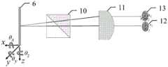
图2为本发明的激光雷达扫描振镜三维角度测量装置;Fig. 2 is the three-dimensional angle measuring device of the laser radar scanning galvanometer of the present invention;
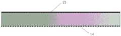
图3为本发明的激光雷达扫描振镜的结构示意图;3 is a schematic structural diagram of a laser radar scanning galvanometer of the present invention;
图4是本发明的激光雷达扫描振镜三维角度测量示意图;4 is a schematic diagram of the three-dimensional angle measurement of the laser radar scanning galvanometer of the present invention;
图5是本发明的激光雷达扫描振镜三维角度测量装置在激光雷达内部的安装示意图;5 is a schematic diagram of the installation of the laser radar scanning galvanometer three-dimensional angle measuring device of the present invention inside the laser radar;
图中:激光器1、准直透镜2、分光棱镜3、聚焦透镜4、探测器5、扫描振镜6、目标物体7、激光器8、准直透镜9、分光棱镜10、聚焦透镜11、激光光斑探测器12、13。In the figure: laser 1,
具体实施方式Detailed ways
以下结合附图和实施例对本发明作进一步阐述。The present invention will be further elaborated below with reference to the accompanying drawings and embodiments.
激光雷达可以探测一定范围内的空间目标物体,其具有比较高的距离测量和角度测量分辨率,距离测量的工作原理一般是基于飞行时间法或者相位法,通过计算在发射激光信号和接收到回波信号的时间内激光的飞行距离测得激光雷达和目标物体之间的距离;角度测量一般是利用角位置传感器测量激光雷达扫描振镜偏转的角度。同时确定目标物体相对于激光雷达的距离和角度,才能准确的确定目标物体。Lidar can detect space target objects within a certain range, and it has relatively high resolution of distance measurement and angle measurement. The working principle of distance measurement is generally based on the time-of-flight method or the phase method. The distance between the laser radar and the target object is measured by the flying distance of the laser within the time of the wave signal; the angle measurement generally uses the angular position sensor to measure the deflection angle of the laser radar scanning galvanometer. At the same time, the distance and angle of the target object relative to the lidar can be determined to accurately determine the target object.
图1是一种激光雷达的原理示意图,所述激光雷达包括:激光器1、准直透镜2、分光棱镜3、聚焦透镜4、探测器5和扫描振镜6。所述激光器1出射激光光束,其初始发散角比较大不能直接用于激光雷达测量,利用准直透镜2对激光光束准直,减小激光光束的发散角,分光棱镜3放置在准直透镜后面,光强为50%的激光光束透射过分光棱镜3经过扫描振镜前表面反射镜反射到远处目标物体7上,其余光强约为50%的激光光束经过分光棱镜3的反射而损耗掉;由于漫反射作用,远处目标物体7产生激光回波信号,部分激光回波信号会照射到扫描振镜6前表面的反射镜上,反射回到分光棱镜3,光强约为50%的激光回波信号经过分光棱镜3的反射面反射到聚焦透镜4,其余光强约为50%的激光回波信号投射过分光棱镜3而损耗掉,探测器5放置在聚焦透镜4的焦点处,经过聚焦透镜4的汇聚作用,激光回波信号照射到探测器5的感光面上,产生相应的电信号,通过信号处理解算出远处目标物体相对于激光雷达的距离信息,扫描振镜的角度信息由其驱动机构扫描电机内部的角位置传感器得到。FIG. 1 is a schematic diagram of the principle of a laser radar. The laser radar includes: a laser 1 , a
图2是本发明的激光雷达扫描振镜三维角度测量装置的结构示意图。所述角度测量装置包括激光器8、准直透镜9、分光棱镜10、聚焦透镜11、和激光光斑探测元件。FIG. 2 is a schematic structural diagram of the three-dimensional angle measuring device of the laser radar scanning galvanometer according to the present invention. The angle measuring device includes a
激光器,用于生成并发射激光光束;a laser for generating and emitting a laser beam;
准直透镜,用于准直激光光束,减小激光光束的发散角;The collimating lens is used to collimate the laser beam and reduce the divergence angle of the laser beam;
分光棱镜,用于偏转激光传播方向,使得激光照射到扫描振镜后表面的反射式衍射光栅上;The beam splitter prism is used to deflect the propagation direction of the laser light, so that the laser light is irradiated on the reflective diffraction grating on the rear surface of the scanning galvanometer;
聚焦透镜,用于将反射式衍射光栅反射的零级衍射光束和正一级衍射光束会聚,使其可以平行入射到两个激光光斑探测器上;The focusing lens is used to converge the zero-order diffracted beam and the positive first-order diffracted beam reflected by the reflective diffraction grating, so that it can be incident on the two laser spot detectors in parallel;
激光光斑探测元件,用于测量零级衍射光斑和正一级衍射光斑的位置。The laser spot detection element is used to measure the position of the zero-order diffraction spot and the positive first-order diffraction spot.
所述的衍射光栅14位于激光雷达的扫描振镜的后表面上,从激光器8发射的激光经准直透镜9后入射至分光棱镜10,通过分光棱镜10反射至扫描振镜后表面的衍射光栅14上,形成零级衍射光束和正一级衍射光束;所述的零级衍射光束和正一级衍射光束分别穿过分光棱镜10,经聚焦透镜11聚焦后入射至激光光斑探测元件上,由激光光斑探测元件接收到零级衍射光斑和正一级衍射光斑。所述的激光光斑探测元件包括并排设置的第一激光光斑探测器12和第二激光光斑探测器13,所述第一激光光斑探测器12设置于聚焦透镜11的焦点处,第二激光光斑探测器13沿正一级衍射光束的偏转方向设置在第一激光光斑探测器12一侧,且所述的扫描振镜6、分光棱镜10、聚焦透镜11和第一激光探测器12沿光轴设置在同一条直线上。The
在本发明的一项具体实施中,所述激光器8发出激光光束,准直透镜9减小激光光束的发散角,光强约为50%的激光光束经过分光棱镜10反射面反射到扫描振镜6后表面的反射式衍射光栅14上,由于衍射作用,零级衍射光束和正一级衍射光束以不同的出射角反射,出射角度与光栅常数和激光波长有关,光强约为50%的零级衍射光束和正一级衍射光束投射过分光棱镜10,由聚焦透镜11分别将零级衍射光束和正一级衍射光束汇聚到激光光斑探测器12和13上,聚焦透镜11与扫描振镜6之间的距离等于聚焦透镜11的焦距。In a specific implementation of the present invention, the
图3是本发明的激光雷达扫描振镜的结构示意图。如图所示,衍射光栅14和激光雷达的扫描振镜6为一体式结构,扫描振镜6前表面为镀膜反射镜,对所选用激光波段具有高反特性,用于偏转激光雷达的测量激光信号以及目标物体漫反射返回的激光回波信号,扫描振镜6后表面镀有反射式衍射光栅,用于实时测量激光雷达工作过程中扫描振镜的三维角位置,反射式衍射光栅是由无数多个等间距狭缝的反射膜,狭缝之间的间距记为d,称为光栅常数。所述的扫描振镜能够在空间转动,在初始状态下,从激光器8发射的激光经准直透镜9和分光棱镜10后垂直入射至扫描振镜后表面的衍射光栅14上,从聚焦透镜11出射的零级衍射光束和正一级衍射光束平行。FIG. 3 is a schematic structural diagram of the laser radar scanning galvanometer of the present invention. As shown in the figure, the
激光雷达工作过程中,扫描振镜激光测量激光信号以一定的角度反射到远处目标物体上,由于漫反射现象,目标物体反射激光回波信号,部分激光信号经过扫描振镜和其他光学元件聚焦到探测器上,计算发射激光信号和接收到激光回波信号的时间差即可得到远处目标物体相对于激光雷达的距离,远处目标物体相对于激光雷达的角度为此时扫描振镜的偏转角度,因此远处目标物体相对于激光雷达便可以唯一确定。如图5所示,本发明的激光雷达扫描振镜三维角度测量装置集成安装在激光雷达内部,可以测量激光雷达工作过程中扫描振镜三个维度的偏转角度。During the working process of the lidar, the laser signal measured by the scanning galvanometer is reflected to the distant target object at a certain angle. Due to the phenomenon of diffuse reflection, the target object reflects the laser echo signal, and part of the laser signal is focused by the scanning galvanometer and other optical components. Go to the detector, calculate the time difference between the transmitted laser signal and the received laser echo signal, and then the distance of the distant target object relative to the laser radar can be obtained. The angle of the distant target object relative to the laser radar is the deflection of the scanning galvanometer at this time. angle, so the distant target object can be uniquely determined relative to the lidar. As shown in FIG. 5 , the three-dimensional angle measurement device of the laser radar scanning galvanometer of the present invention is integrated and installed inside the laser radar, and can measure the deflection angles of the scanning galvanometer in three dimensions during the working process of the laser radar.
图4是本发明扫描振镜三维角度测量示意图。默认状态下,即所述扫描振镜6没有偏转时,零级衍射光斑和正一级衍射光斑分别照射在两个激光光斑探测器12和13的中心位置分别记为A0和B0,两个光斑中心的距离可以计算得到:


假定扫描振镜6某一时刻只绕x轴旋转了θx角度,激光光斑探测器12上的衍射光斑的中心位置不会发生变化,仍为A0,而激光光斑探测器13上的衍射光斑的中心位置偏移到新位置B3。不考虑其他因素干扰,则零级衍射光斑在激光光斑探测器12上的位移为0,而正一级衍射光斑在激光光斑探测器13上的位移|B0B3|,且有|B0B3|=2*f*tanθx。Assuming that the
假定扫描振镜6某一时刻只绕y轴旋转了θy角度,激光光斑探测器12和13上的衍射光斑的中心位置偏移到新位置A2和B2。不考虑其他因素干扰,则零级衍射光斑在激光光斑探测器12上的位移|A0A2|和正一级衍射光斑在激光光斑探测器13上的位移|B0B2|相等,且有|A0A2|=|B0B2|=2*f*tanθy。Assuming that the
假定扫描振镜6某一时刻只绕z轴旋转了θz角度,激光光斑探测器12和13上的衍射光斑的中心位置偏移到新位置A1和B1。不考虑其他因素干扰,则零级衍射光斑在激光光斑探测器12上的位移|A0A1|和正一级衍射光斑在激光光斑探测器13上的位移|B0B1|相等,且有|A0A1|=|B0B1|=2*f*tanθz。Assuming that the
在激光雷达工作过程中,扫描振镜的绕动方向是预先设置的,根据上述推理可知,通过激光光斑探测器12上零级衍射光斑的位移和激光光斑探测器13上正一级衍射光斑的位移,即可计算得到扫描振镜绕某一轴旋转的角度。During the working process of the laser radar, the orbiting direction of the scanning galvanometer is preset. According to the above reasoning, it can be known that the displacement of the zero-order diffraction spot on the
在本发明的一项具体实施中,扫描振镜旋转角度的测量方法具体为:In a specific implementation of the present invention, the measuring method of the rotation angle of the scanning galvanometer is specifically:
步骤1:初始状态下,从激光器8发射的激光经准直透镜9后入射至分光棱镜10,通过分光棱镜10反射至扫描振镜后表面的衍射光栅14上,形成零级衍射光束和正一级衍射光束,从衍射光栅反射的正一级衍射光束与零级衍射光束之间形成一定的偏转角;Step 1: In the initial state, the laser light emitted from the
步骤2:所述零级衍射光束垂直反射至分光棱镜10,并穿过分光棱镜10后垂直入射至聚焦透镜11,经会聚后在第一激光探测器12的中心位置处形成零级衍射光斑,记录初始状态下的零级衍射光斑位置A0;Step 2: The zero-order diffracted beam is vertically reflected to the
所述正一级衍射光束以一定角度反射至分光棱镜10,并穿过分光棱镜10后入射至聚焦透镜11,经会聚后的正一级衍射光束与零级衍射光束平行,在第二激光探测器13的中心位置处形成正一级衍射光斑,记录初始状态下的正一级衍射光斑位置B0;The positive first-order diffracted beam is reflected to the
步骤3:设置扫描振镜的绕动方向,所述扫描振镜在驱动机构带动下绕定轴转动,记录实时转动过程中的零级衍射光斑和正一级衍射光斑的位置变化实现旋转角度的实时测量。所述扫描振镜绕定轴旋转的角度计算公式为:Step 3: Set the orbiting direction of the scanning galvanometer. The scanning galvanometer rotates around a fixed axis under the drive of the drive mechanism, and records the positional changes of the zero-order diffraction spot and the positive first-order diffraction spot during the real-time rotation to realize the real-time rotation angle. Measurement. The calculation formula of the angle of rotation of the scanning galvanometer around the fixed axis is:

d=|B0Bt|d=|B0 Bt |
其中,Bt为t时刻正一级衍射光斑的位置,d=|B0Bt|为t时间段内正一级衍射光斑变化的距离,θt为t时刻扫描振镜绕定轴旋转的角度,f为聚焦透镜11的焦距。Among them, Bt is the position of the positive first-order diffraction spot at time t, d=|B0 Bt | is the change distance of the positive first-order diffraction spot in the t time period, θt is the rotation of the scanning galvanometer around the fixed axis at time t angle, f is the focal length of the focusing
在本发明的一项具体实施中,为了使得角度测量结果更加准确,当预设扫描振镜的绕动方向为沿x轴绕动时,d为正一级衍射光斑变化的距离;当预设扫描振镜的绕动方向为沿y轴或者z轴绕动时,可以令d为正一级衍射光斑变化的距离和零级衍射光斑变化的距离的均值。具体为:In a specific implementation of the present invention, in order to make the angle measurement result more accurate, when the orbiting direction of the scanning galvanometer is preset to orbit along the x-axis, d is the distance of the change of the positive first-order diffraction spot; When the orbiting direction of the scanning galvanometer is along the y-axis or the z-axis, d can be set to be the average value of the variation distance of the positive first-order diffraction spot and the variation distance of the zero-order diffraction spot. Specifically:

其中,At为t时刻零级衍射光斑的位置,|A0 At|为t时间段内零级衍射光斑变化的距离,Bt为t时刻正一级衍射光斑的位置,|B0 Bt|为t时间段内正一级衍射光斑变化的距离,θt为t时刻扫描振镜绕定轴旋转的角度,f为聚焦透镜11的焦距。Among them, At is the position of the zero-order diffraction spot at time t, |A0 At | is the variation distance of the zero-order diffraction spot in the t time period, Bt is the position of the positive first-order diffraction spot at time t, |B0 Bt | is the change distance of the positive first-order diffraction spot in the t time period, θt is the rotation angle of the scanning galvanometer around the fixed axis at time t, and f is the focal length of the focusing
零级衍射光斑的设置一方面用于降低测量误差,另一方面用于测量系统的初始化校正,使得初始状态下的零级衍射光束会聚后在第一激光探测器12的中心位置处。The setting of the zero-order diffracted light spot is used to reduce the measurement error on the one hand, and to initialize and correct the measurement system on the other hand, so that the zero-order diffracted light beam in the initial state converges at the center position of the
以上列举的仅是本发明的具体实施例。显然,本发明不限于以上实施例,还可以有许多变形。本领域的普通技术人员能从本发明公开的内容直接导出或联想到的所有变形,均应认为是本发明的保护范围。The foregoing enumerations are merely specific embodiments of the present invention. Obviously, the present invention is not limited to the above embodiments, and many modifications are possible. All deformations that those of ordinary skill in the art can directly derive or associate from the disclosure of the present invention shall be considered as the protection scope of the present invention.
Claims (9)
Translated fromChinese
Priority Applications (1)
| Application Number | Priority Date | Filing Date | Title |
|---|---|---|---|
| CN202010716357.5ACN111982028A (en) | 2020-07-23 | 2020-07-23 | A laser radar scanning galvanometer three-dimensional angle measurement device and method |
Applications Claiming Priority (1)
| Application Number | Priority Date | Filing Date | Title |
|---|---|---|---|
| CN202010716357.5ACN111982028A (en) | 2020-07-23 | 2020-07-23 | A laser radar scanning galvanometer three-dimensional angle measurement device and method |
Publications (1)
| Publication Number | Publication Date |
|---|---|
| CN111982028Atrue CN111982028A (en) | 2020-11-24 |
Family
ID=73438087
Family Applications (1)
| Application Number | Title | Priority Date | Filing Date |
|---|---|---|---|
| CN202010716357.5APendingCN111982028A (en) | 2020-07-23 | 2020-07-23 | A laser radar scanning galvanometer three-dimensional angle measurement device and method |
Country Status (1)
| Country | Link |
|---|---|
| CN (1) | CN111982028A (en) |
Cited By (14)
| Publication number | Priority date | Publication date | Assignee | Title |
|---|---|---|---|---|
| CN112630748A (en)* | 2020-12-11 | 2021-04-09 | 中国空空导弹研究院 | Laser pulse time interval processing method and laser radar detection system |
| CN112683198A (en)* | 2020-12-01 | 2021-04-20 | 江西省中久光电产业研究院 | Three-degree-of-freedom angle photoelectric measuring device and measuring method thereof |
| CN112710256A (en)* | 2020-12-19 | 2021-04-27 | 重庆大学 | Electromechanical performance test system and method for scanning grating micro-mirror |
| CN112833823A (en)* | 2021-02-23 | 2021-05-25 | 北方民族大学 | A new type of sensor based on time measuring angle and its angle measuring method |
| CN112923873A (en)* | 2021-03-11 | 2021-06-08 | 北方民族大学 | A laser scanning device and angle measuring sensor and method based on laser scanning |
| CN113188454A (en)* | 2021-05-22 | 2021-07-30 | 北方民族大学 | Displacement sensor based on time difference and measuring method thereof |
| CN113281720A (en)* | 2021-05-13 | 2021-08-20 | 北京理工大学 | Laser three-dimensional imaging scanning method based on dielectric elastic drive |
| CN113932908A (en)* | 2021-09-29 | 2022-01-14 | 北京理工大学 | Measuring system and measuring method for vibration parameters of MEMS scanning galvanometer |
| CN115061116A (en)* | 2022-06-08 | 2022-09-16 | 北京理工大学 | Area array block scanning lidar launch system based on MEMS galvanometer |
| CN115077392A (en)* | 2022-06-14 | 2022-09-20 | 郑州轻工业大学 | Light beam spot displacement amplification measuring system and measuring method |
| CN116183012A (en)* | 2022-11-18 | 2023-05-30 | 中国船舶重工集团公司七五0试验场 | Laser non-contact type object vibration detection and monitoring method |
| CN116540211A (en)* | 2023-04-27 | 2023-08-04 | 华中科技大学 | A Polarization Spectral Imaging LiDAR System |
| CN117968582A (en)* | 2024-02-07 | 2024-05-03 | 中国科学院长春光学精密机械与物理研究所 | A grating line error detection device and method |
| WO2025175882A1 (en)* | 2024-02-19 | 2025-08-28 | 华为技术有限公司 | Angle measurement apparatus and lidar scanning system |
Citations (4)
| Publication number | Priority date | Publication date | Assignee | Title |
|---|---|---|---|---|
| US20110090317A1 (en)* | 2009-10-20 | 2011-04-21 | Industrial Technology Research Institute | Stereovision system and method for calcualting distance between object and diffractive optical element |
| CN105865637A (en)* | 2016-04-01 | 2016-08-17 | 中北大学 | A spaceborne high-angle-resolution laser warning detection method and device |
| CN109470177A (en)* | 2018-12-05 | 2019-03-15 | 哈尔滨工业大学 | Three-dimensional angle measurement method and device based on double grating |
| CN109579744A (en)* | 2018-12-05 | 2019-04-05 | 哈尔滨工业大学 | Trailing type three-dimensional photoelectric auto-collimation method and apparatus based on grating |
- 2020
- 2020-07-23CNCN202010716357.5Apatent/CN111982028A/enactivePending
Patent Citations (4)
| Publication number | Priority date | Publication date | Assignee | Title |
|---|---|---|---|---|
| US20110090317A1 (en)* | 2009-10-20 | 2011-04-21 | Industrial Technology Research Institute | Stereovision system and method for calcualting distance between object and diffractive optical element |
| CN105865637A (en)* | 2016-04-01 | 2016-08-17 | 中北大学 | A spaceborne high-angle-resolution laser warning detection method and device |
| CN109470177A (en)* | 2018-12-05 | 2019-03-15 | 哈尔滨工业大学 | Three-dimensional angle measurement method and device based on double grating |
| CN109579744A (en)* | 2018-12-05 | 2019-04-05 | 哈尔滨工业大学 | Trailing type three-dimensional photoelectric auto-collimation method and apparatus based on grating |
Cited By (19)
| Publication number | Priority date | Publication date | Assignee | Title |
|---|---|---|---|---|
| CN112683198B (en)* | 2020-12-01 | 2023-02-21 | 江西省中久光电产业研究院 | Three-degree-of-freedom angle photoelectric measuring device and measuring method thereof |
| CN112683198A (en)* | 2020-12-01 | 2021-04-20 | 江西省中久光电产业研究院 | Three-degree-of-freedom angle photoelectric measuring device and measuring method thereof |
| CN112630748B (en)* | 2020-12-11 | 2023-05-23 | 中国空空导弹研究院 | Laser pulse time interval processing method and laser radar detection system |
| CN112630748A (en)* | 2020-12-11 | 2021-04-09 | 中国空空导弹研究院 | Laser pulse time interval processing method and laser radar detection system |
| CN112710256A (en)* | 2020-12-19 | 2021-04-27 | 重庆大学 | Electromechanical performance test system and method for scanning grating micro-mirror |
| CN112833823A (en)* | 2021-02-23 | 2021-05-25 | 北方民族大学 | A new type of sensor based on time measuring angle and its angle measuring method |
| CN112923873A (en)* | 2021-03-11 | 2021-06-08 | 北方民族大学 | A laser scanning device and angle measuring sensor and method based on laser scanning |
| CN113281720B (en)* | 2021-05-13 | 2023-02-28 | 北京理工大学 | A laser three-dimensional imaging scanning method based on dielectric elastic drive |
| CN113281720A (en)* | 2021-05-13 | 2021-08-20 | 北京理工大学 | Laser three-dimensional imaging scanning method based on dielectric elastic drive |
| CN113188454A (en)* | 2021-05-22 | 2021-07-30 | 北方民族大学 | Displacement sensor based on time difference and measuring method thereof |
| CN113932908A (en)* | 2021-09-29 | 2022-01-14 | 北京理工大学 | Measuring system and measuring method for vibration parameters of MEMS scanning galvanometer |
| CN113932908B (en)* | 2021-09-29 | 2023-02-28 | 北京理工大学 | Measuring system and measuring method for vibration parameters of MEMS scanning galvanometer |
| CN115061116A (en)* | 2022-06-08 | 2022-09-16 | 北京理工大学 | Area array block scanning lidar launch system based on MEMS galvanometer |
| CN115061116B (en)* | 2022-06-08 | 2025-08-19 | 北京理工大学 | Area array block scanning laser radar transmitting system based on MEMS vibrating mirror |
| CN115077392A (en)* | 2022-06-14 | 2022-09-20 | 郑州轻工业大学 | Light beam spot displacement amplification measuring system and measuring method |
| CN116183012A (en)* | 2022-11-18 | 2023-05-30 | 中国船舶重工集团公司七五0试验场 | Laser non-contact type object vibration detection and monitoring method |
| CN116540211A (en)* | 2023-04-27 | 2023-08-04 | 华中科技大学 | A Polarization Spectral Imaging LiDAR System |
| CN117968582A (en)* | 2024-02-07 | 2024-05-03 | 中国科学院长春光学精密机械与物理研究所 | A grating line error detection device and method |
| WO2025175882A1 (en)* | 2024-02-19 | 2025-08-28 | 华为技术有限公司 | Angle measurement apparatus and lidar scanning system |
Similar Documents
| Publication | Publication Date | Title |
|---|---|---|
| CN111982028A (en) | A laser radar scanning galvanometer three-dimensional angle measurement device and method | |
| US10444361B2 (en) | Laser tracker having two measurement functionalities | |
| CN106595480B (en) | For measuring the laser measurement system and method for shaft six degree of freedom geometric error | |
| JP4601798B2 (en) | Position measurement setting system | |
| JP4531965B2 (en) | Vibration detection device, rotating laser device with vibration detection device, and position measurement setting system with vibration detection correction device | |
| US4897536A (en) | Optical axis displacement sensor with cylindrical lens means | |
| JP2020508457A (en) | Sensor system and method | |
| CN107643055B (en) | Self-referenced collimation optical path system based on polarized beam and method for calculating measured angle | |
| US4483618A (en) | Laser measurement system, virtual detector probe and carriage yaw compensator | |
| CN111412832B (en) | Semiconductor laser six-degree-of-freedom error measurement system based on interferometer module | |
| CN210015229U (en) | Distance detection device | |
| CN109579780A (en) | One kind being based on polarization spectro auto-collimation three-dimensional perspective measuring device and method | |
| CN109579777B (en) | Double-light-source high-precision anti-interference large-working-distance auto-collimation device and method | |
| EP0208276B1 (en) | Optical measuring device | |
| TWI452262B (en) | Interferometer system for simultaneous measurement of linear displacement and tilt angle | |
| CN109470177A (en) | Three-dimensional angle measurement method and device based on double grating | |
| CN102645178A (en) | Dual-frequency interference based facial contour measuring device and method | |
| CN109579744B (en) | Following type three-dimensional photoelectric auto-collimation method and device based on grating | |
| TWI502170B (en) | Optical measurement system and method for measuring linear displacement, rotation and rolling angles | |
| CN102645179A (en) | Surface type measuring device and method based on double-frequency interference | |
| CN114894124B (en) | Interference type angle measurement system and measurement method | |
| Chen et al. | Effects of incident beam deviation from the center of a cat's eye retro-reflector on the measurement accuracy of a laser tracing system | |
| CN218066329U (en) | Ultra-long-distance high-precision micro-nano displacement measuring device | |
| JPH02501958A (en) | Focus detection system for use in optical measurement systems | |
| JPH095059A (en) | Flatness measuring device |
Legal Events
| Date | Code | Title | Description |
|---|---|---|---|
| PB01 | Publication | ||
| PB01 | Publication | ||
| SE01 | Entry into force of request for substantive examination | ||
| SE01 | Entry into force of request for substantive examination | ||
| RJ01 | Rejection of invention patent application after publication | Application publication date:20201124 | |
| RJ01 | Rejection of invention patent application after publication |