CN111977551A - Elevator trolley and continuous elevator - Google Patents
Elevator trolley and continuous elevatorDownload PDFInfo
- Publication number
- CN111977551A CN111977551ACN202010758402.3ACN202010758402ACN111977551ACN 111977551 ACN111977551 ACN 111977551ACN 202010758402 ACN202010758402 ACN 202010758402ACN 111977551 ACN111977551 ACN 111977551A
- Authority
- CN
- China
- Prior art keywords
- hoist
- frame
- flexible member
- trolley
- hoist trolley
- Prior art date
- Legal status (The legal status is an assumption and is not a legal conclusion. Google has not performed a legal analysis and makes no representation as to the accuracy of the status listed.)
- Granted
Links
Images


Classifications
- B—PERFORMING OPERATIONS; TRANSPORTING
- B66—HOISTING; LIFTING; HAULING
- B66F—HOISTING, LIFTING, HAULING OR PUSHING, NOT OTHERWISE PROVIDED FOR, e.g. DEVICES WHICH APPLY A LIFTING OR PUSHING FORCE DIRECTLY TO THE SURFACE OF A LOAD
- B66F7/00—Lifting frames, e.g. for lifting vehicles; Platform lifts
- B66F7/02—Lifting frames, e.g. for lifting vehicles; Platform lifts with platforms suspended from ropes, cables, or chains or screws and movable along pillars
- B—PERFORMING OPERATIONS; TRANSPORTING
- B65—CONVEYING; PACKING; STORING; HANDLING THIN OR FILAMENTARY MATERIAL
- B65G—TRANSPORT OR STORAGE DEVICES, e.g. CONVEYORS FOR LOADING OR TIPPING, SHOP CONVEYOR SYSTEMS OR PNEUMATIC TUBE CONVEYORS
- B65G17/00—Conveyors having an endless traction element, e.g. a chain, transmitting movement to a continuous or substantially-continuous load-carrying surface or to a series of individual load-carriers; Endless-chain conveyors in which the chains form the load-carrying surface
- B65G17/06—Conveyors having an endless traction element, e.g. a chain, transmitting movement to a continuous or substantially-continuous load-carrying surface or to a series of individual load-carriers; Endless-chain conveyors in which the chains form the load-carrying surface having a load-carrying surface formed by a series of interconnected, e.g. longitudinal, links, plates, or platforms
- B—PERFORMING OPERATIONS; TRANSPORTING
- B65—CONVEYING; PACKING; STORING; HANDLING THIN OR FILAMENTARY MATERIAL
- B65G—TRANSPORT OR STORAGE DEVICES, e.g. CONVEYORS FOR LOADING OR TIPPING, SHOP CONVEYOR SYSTEMS OR PNEUMATIC TUBE CONVEYORS
- B65G29/00—Rotary conveyors, e.g. rotating discs, arms, star-wheels or cones
- B65G29/02—Rotary conveyors, e.g. rotating discs, arms, star-wheels or cones for inclined or vertical transit
- B—PERFORMING OPERATIONS; TRANSPORTING
- B65—CONVEYING; PACKING; STORING; HANDLING THIN OR FILAMENTARY MATERIAL
- B65G—TRANSPORT OR STORAGE DEVICES, e.g. CONVEYORS FOR LOADING OR TIPPING, SHOP CONVEYOR SYSTEMS OR PNEUMATIC TUBE CONVEYORS
- B65G47/00—Article or material-handling devices associated with conveyors; Methods employing such devices
- B65G47/34—Devices for discharging articles or materials from conveyor
- B—PERFORMING OPERATIONS; TRANSPORTING
- B66—HOISTING; LIFTING; HAULING
- B66F—HOISTING, LIFTING, HAULING OR PUSHING, NOT OTHERWISE PROVIDED FOR, e.g. DEVICES WHICH APPLY A LIFTING OR PUSHING FORCE DIRECTLY TO THE SURFACE OF A LOAD
- B66F7/00—Lifting frames, e.g. for lifting vehicles; Platform lifts
- B66F7/28—Constructional details, e.g. end stops, pivoting supporting members, sliding runners adjustable to load dimensions
Landscapes
- Engineering & Computer Science (AREA)
- Mechanical Engineering (AREA)
- Life Sciences & Earth Sciences (AREA)
- Geology (AREA)
- Structural Engineering (AREA)
- Intermediate Stations On Conveyors (AREA)
Abstract
Translated fromChinese
Description
Translated fromChinese技术领域technical field
本发明涉及一种提升机小车以及连续提升机,主要应用在物流输送的技术领域。The invention relates to a hoist trolley and a continuous hoist, which are mainly used in the technical field of logistics transportation.
背景技术Background technique
目前在物流输送的相关技术领域,连续式提升机的小车主要有链板结构和叉式结构,均存在结构强度一般,移动过程中稳定性平衡性一般的问题,由此会导致分流货物风险大的问题,另外对于易碎品货物的保护性较差。At present, in the related technical field of logistics transportation, the trolleys of the continuous hoist mainly have chain plate structure and fork structure, both of which have the problems of general structural strength and general stability and balance during the movement process, which will lead to high risk of diverting goods. problem, and poor protection for fragile goods.
例如现有技术公开号CN207107628U公开了一种连续提升机,包括升降架、进货输送装置、出货输送装置、链轮传动机构,所述升降架内位于进货通道口处的前后侧分别设有第一转动轴装置和第二转动轴装置,第一转动轴装置下方设置有主传动轴装置,第二转动轴装置下方设置有涨紧轴装置;出货通道口处的前后侧设有第三转动轴装置和第四转动轴装置,第三转动轴装置的上方安装有上过渡转动轴装置,下方设置有下过渡转动轴装置;升降架内侧顶部设有第五转动轴装置和第六转动轴装置,升降架内对称布置有绕接相应链轮的两条前回转链条和两条后回转链条,并在回转链条上相接有可平置的链板。该连续提升机在使用时,链板随着链条带动货物垂直上升到高处,然后链条继续上升后下降,下侧的链板继续输送货物,周而复始,可以连续作业。链板作为承载货物的部件,结构极为简易与链条固定连接后保持水平稳定性较弱,容易出现晃动的情况,容易造成小件货物运输风险,另外进货与出货必须在链板保持水平状态的移动路径,因此提升机的成本也相对较高。For example, prior art publication number CN207107628U discloses a continuous hoist, including a lifting frame, an incoming conveying device, an outgoing conveying device, and a sprocket transmission mechanism. A rotating shaft device and a second rotating shaft device, a main transmission shaft device is arranged below the first rotating shaft device, a tensioning shaft device is arranged below the second rotating shaft device; A shaft device and a fourth rotating shaft device, an upper transitional rotating shaft device is installed above the third rotating shaft device, and a lower transitional rotating shaft device is installed below; the inner top of the lifting frame is provided with a fifth rotating shaft device and a sixth rotating shaft device In the lifting frame, two front slewing chains and two rear slewing chains are arranged symmetrically around the corresponding sprockets, and the slewing chains are connected with chain plates that can be placed horizontally. When the continuous hoist is in use, the chain plate drives the goods vertically to a high place with the chain, then the chain continues to rise and then descend, and the chain plate on the lower side continues to transport the goods, and it can work continuously. The chain plate, as the part that carries the goods, has a very simple structure and is fixedly connected to the chain to maintain horizontal stability, which is prone to shaking, which is easy to cause the risk of small cargo transportation. The moving path, so the cost of the hoist is also relatively high.
发明内容SUMMARY OF THE INVENTION
本发明要解决的技术问题是提供一种提升机小车以及连续提升机,提升机小车具有牢固的结构强度以及移动过程中较高的稳定性,并具备送出货物的能力,连续提升机以多进多出的设置提高了分流能力。The technical problem to be solved by the present invention is to provide a hoist trolley and a continuous hoist. The hoist trolley has firm structural strength and high stability during movement, and has the ability to send out goods. The extra settings improve the diversion capability.
本发明是通过以下技术方案来实现的。The present invention is achieved through the following technical solutions.
一种提升机小车,包括车架以及水平设置的分流承载部,所述分流承载部固定连接在所述车架并用以承载货物,所述车架具有四个相互平行且水平设置的轴,并且用以连接传动机构。A hoist trolley includes a frame and a horizontally arranged split bearing portion, the split bearing portion is fixedly connected to the frame and used to carry goods, the frame has four mutually parallel and horizontally arranged shafts, and Used to connect the transmission mechanism.
作为本发明的进一步改进,所述车架呈U型结构,所述车架中部的两侧分别具有一个轴,所述车架的两端分别具有一个轴,所述分流承载部位于车架所围区域的中间位置。As a further improvement of the present invention, the frame has a U-shaped structure, two sides of the middle of the frame are respectively provided with a shaft, both ends of the frame are respectively provided with a shaft, and the split bearing portion is located at the position of the frame. the middle of the surrounding area.
作为本发明的进一步改进,所述车架包括两个连杆、相互平行的第一连接轴以及两个第二连接轴,两个所述连杆的一端分别固定连接在所述第一连接轴的两端,两个所述连杆的另一端分别固定连接两个第二连接轴,所述分流承载部与所述第一连接轴固定连接,所述第一连接轴的两侧以及两个第二连接轴用即作为与传动机构连接的四个轴。As a further improvement of the present invention, the frame includes two connecting rods, a first connecting shaft parallel to each other, and two second connecting shafts, and one ends of the two connecting rods are respectively fixedly connected to the first connecting shafts two ends of the connecting rod, the other ends of the two connecting rods are respectively fixedly connected to two second connecting shafts, the shunt bearing part is fixedly connected to the first connecting shaft, the two sides of the first connecting shaft and the two The second connecting shaft is used as the four shafts connected with the transmission mechanism.
作为本发明的进一步改进,所述承载部设置为皮带机。As a further improvement of the present invention, the carrying portion is configured as a belt conveyor.
作为本发明的进一步改进,所述提升机小车设有传感器,用以测量皮带机所载货物沿其输送方向的长度。As a further improvement of the present invention, the hoist trolley is provided with a sensor to measure the length of the goods carried by the belt conveyor along its conveying direction.
一种连续提升机,包括传动机构以及由传动机构驱动的至少一个所述提升机小车,所述提升机小车在传动机构的驱动下,其移动的总路径呈闭环状且包括两个竖向路径,对应两个竖向路径分别设有多层入口输送道、多层出口输送道,并可分别与移动至相应位置的提升机小车货物对接。A continuous hoist includes a transmission mechanism and at least one of the hoist trolleys driven by the transmission mechanism. The hoist trolley is driven by the transmission mechanism, and the total moving path of the hoist trolley is a closed loop and includes two vertical paths Corresponding to the two vertical paths, there are respectively multi-layer inlet conveying lanes and multi-layer outlet conveying lanes, which can be respectively docked with the goods of the hoist trolley that move to the corresponding position.
作为本发明的进一步改进,所述传动机构包括两个平行间隔且并排的由多个传动轮传动连接且呈环型的第一挠性件、以及两个平行间隔且并排的由多个传动轮传动连接且呈环型的第二挠性件,所述第一挠性件与所述第二挠性件形状大小相同并且均具有两个竖向部分,所述第一挠性件与所述第二挠性件平行间隔且不并排,所述提升机小车同时与两个第一挠性件、两个第二挠性件活动连接。As a further improvement of the present invention, the transmission mechanism includes two parallel spaced and side-by-side transmission-connected and annular first flexible members by a plurality of transmission wheels, and two parallel spaced and side by side by a plurality of transmission wheels A transmission-connected and annular second flexible member, the first flexible member and the second flexible member have the same shape and size and both have two vertical portions, the first flexible member and the second flexible member have the same shape and size The second flexible members are spaced apart in parallel and not side by side, and the hoist trolley is movably connected with the two first flexible members and the two second flexible members at the same time.
作为本发明的进一步改进,所述第一挠性件与所述第二挠性件为由连续的链节连接而成的链条,对应所述第一挠性件以及第二挠性件的所有传动轮均为链轮。As a further improvement of the present invention, the first flexible member and the second flexible member are chains connected by continuous chain links, corresponding to all of the first flexible member and the second flexible member. The transmission wheels are all sprockets.
作为本发明的进一步改进,两个所述第一挠性件或第二挠性件的链节滑动套设在提升机小车的第一连接轴的两侧并且关于第一连接轴对称,两个所述第二挠性件或第一挠性件的链节分别滑动套设在提升机小车的两个第二连接轴。As a further improvement of the present invention, the chain links of the two first flexible members or the second flexible members are slidably sleeved on both sides of the first connecting shaft of the hoist trolley and are symmetrical about the first connecting shaft, and the two The second flexible member or the chain links of the first flexible member are respectively slidably sleeved on the two second connecting shafts of the hoist trolley.
作为本发明的进一步改进,所述入口输送道设置有传感器,用以测量入口输送道所载货物沿其输送方向的长度。As a further improvement of the present invention, a sensor is provided on the entrance conveying lane to measure the length of the goods carried in the entrance conveying lane along its conveying direction.
本发明的有益效果:Beneficial effects of the present invention:
本发明的提升机小车,其车架具有较好的结构强度,通过四个位于车架本体的连接点作为支撑可以提高其移动过程中的稳定性,维持水平状态避免出现倾斜的现象,另外其分流承载部具有动力,适合于小件货物或软包装货物的分流;本发明的连续提升机实现了货物的多进多出,并且将货物分流进行路径分流至分拣机对应层,并最终分拣至目标格口,连续提升机通过巧妙且合理的传动机构,实现了提升机小车最短路径的循环移动,配合多进多出的分流模式,达到了提高效率的技术目的,另外通过两个分别设置在入口输送道以及分流承载部的感应器,可适应于不同长度货物的输送,起到保护货物尤其是易碎品货物的作用。The hoist trolley of the present invention has a frame with good structural strength, and the four connection points located on the frame body can be used as supports to improve the stability during its movement, maintain a horizontal state, and avoid the phenomenon of tilting. The diversion carrying part has power and is suitable for diversion of small goods or soft packaged goods; the continuous elevator of the present invention realizes multiple in and multiple out of goods, and diverts the goods to the corresponding layer of the sorter, and finally sorts To the target grid, the continuous hoist realizes the shortest path of the hoist trolley through the ingenious and reasonable transmission mechanism, and cooperates with the multi-in and multi-out diversion mode to achieve the technical purpose of improving efficiency. The sensors in the inlet conveying channel and the shunt bearing part can be adapted to the transportation of goods of different lengths, and play a role in protecting the goods, especially the fragile goods.
附图说明Description of drawings
下面将通过附图详细描述本发明中优选实施案例,以助于理解本发明的目的和优点,其中:The preferred embodiments of the present invention will be described in detail below through the accompanying drawings to help understand the purpose and advantages of the present invention, wherein:
图1为多层分拣总成的正视示意图;Figure 1 is a schematic front view of a multi-layer sorting assembly;
图2为多层分拣总成的俯视示意图;Figure 2 is a schematic top view of a multi-layer sorting assembly;
图3为连续提升机、入口输送道、出口输送道布置情况的第一种实施案例示意图;Figure 3 is a schematic diagram of the first implementation case of the arrangement of the continuous hoist, the inlet conveying path and the exit conveying path;
图4为连续提升机、入口输送道、出口输送道布置情况的第二种实施案例示意图;Figure 4 is a schematic diagram of the second implementation case of the arrangement of the continuous hoist, the inlet conveying path and the exit conveying path;
图5为连续提升机、入口输送道、出口输送道布置情况的第三种实施案例示意图;Figure 5 is a schematic diagram of the third implementation case of the arrangement of the continuous hoist, the inlet conveying path and the exit conveying path;
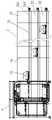
图6为连续提升机的正视示意图;6 is a schematic front view of a continuous hoist;
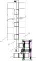
图7为连续提升机的俯视示意图;Fig. 7 is the top view schematic diagram of continuous elevator;
图8为入口输送道与连续提升机的侧视示意图;Figure 8 is a schematic side view of the inlet conveying channel and the continuous elevator;
图9为出口输送道与连续提升机的侧视示意图;Figure 9 is a schematic side view of the outlet conveying channel and the continuous elevator;
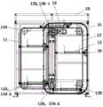
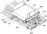
图10为提升机小车的正视示意图;Figure 10 is a schematic front view of the hoist trolley;
图11为提升机小车的俯视示意图;Figure 11 is a schematic top view of the hoist trolley;
图12为取电刷与供电滑触线的关系示意图;Figure 12 is a schematic diagram of the relationship between the brush and the power supply trolley;
图13为分拣机的侧视示意图;Figure 13 is a schematic side view of the sorter;
图14为出口输送道、分拣机布置情况的第一种实施案例示意图;Figure 14 is a schematic diagram of the first implementation case of the arrangement of the outlet conveying lane and the sorter;
图15为出口输送道、分拣机布置情况的第二种实施案例示意图;Figure 15 is a schematic diagram of the second implementation case of the arrangement of the outlet conveying lane and the sorter;
图16为往复式小车的轴测示意图;Fig. 16 is the axonometric schematic diagram of the reciprocating trolley;
图17为格口、目的地布置情况的第一种实施案例示意图;Fig. 17 is a schematic diagram of the first implementation case of the arrangement of grid ports and destinations;
图18为格口、目的地布置情况的第二种实施案例示意图。FIG. 18 is a schematic diagram of the second implementation case of the arrangement of grid ports and destinations.
具体实施方式Detailed ways
下面根据附图和实施案例对本发明作进一步详细说明。The present invention will be further described in detail below according to the accompanying drawings and implementation examples.
在本说明书中提到或者可能提到的上、下、左、右、前、后、正面、背面、顶部、底部等方位用语是相对于各附图中所示的构造进行定义的,词语“内”和“外”分别指的是朝向或远离特定部件几何中心的方向它们是相对的概念,因此有可能会根据其所处不同位置、不同使用状态而进行相应地变化。所以,也不应当将这些或者其他的方位用语解释为限制性用语。Orientation terms such as upper, lower, left, right, front, rear, front, back, top, bottom, etc. mentioned or possibly mentioned in this specification are defined relative to the configurations shown in the drawings, the word "" "Inner" and "outer" refer to directions toward or away from the geometric center of a particular component, respectively, and they are relative concepts, so they may vary accordingly according to their different positions and different states of use. Therefore, these and other terms of orientation should not be construed as limiting.
参照图1、图2,一种多层分拣总成,包括:连续提升机1、分拣机2、多层入口输送道3、多层出口输送道4,在一竖向范围内设有多层所述入口输送道3,在另一竖向范围内设有多层所述出口输送道4,所述连续提升机1分别与多层入口输送道3以及多层出口输送道4货物对接,多层出口输送道4同时与分拣机2货物对接,即连续提升机1的工作模式为多进多出,多层分拣总成大致的输送流程如下:多层入口输送道3输将各自层的货物送入连续提升机1,连续提升机1将货物分流至对应的出口输送道4,再由分拣机2分层分拣。Referring to Figure 1 and Figure 2, a multi-layer sorting assembly includes: a
关于连续提升机1与入口输送道3、出口输送道4的具体布置,在第一种实施案例中,如图3所示,连续提升机1的两侧均设有入口输送道3以及多层出口输送道4,在第二种实施案例中,如图4所示,连续提升机1的两侧设有入口输送道3、单侧设由出口输送道4,在第三种实施案例中,如图5所示,连续提升机1的单侧设有入口输送道3、两侧设有出口输送道4。具体如何设置根据具体应用情况而定。Regarding the specific arrangement of the
参照图6、图7,所述连续提升机1包括提升机框架10以及安装设置在所述提升机框架10内的第一挠性件11、第二挠性件12、多个提升机小车13,所述第一挠性件11与第二挠性件12均由四个链轮110、120传动连接,并且为相同的环型构件,两者在形状以及运行方向均是相同的,具体的,两者大致呈矩形的形状。第一挠性件11与第二挠性件12是平行间隔,并且不并排的位置关系。另外,第一挠性件11具有两个竖向部分,一为上升部分,另一为下降部分,以图2视角为参考,第一挠性件11沿顺时针方向运行,其左侧的竖向部分为上升部分,右侧的竖向部分为下降部分,同样的,第二挠性件12左侧的竖向部分为上升部分,右侧的竖向部分为下降部分。所述提升机小车13是连续排列设置的,其整体维持水平状态,并且同时与第一挠性件11、第二挠性件12活动连接。因此提升机小车13移动的总路径匹配第一挠性件11、第二挠性件12的形状,为矩形的循环总路径,对应第一挠性件11、第二挠性件12的运行方向,提升机小车13移动的总路径由左侧竖向上升路径、上方平向右移路径、右侧竖向下降路径、下方平向左移路径衔接而成。6 and 7 , the
参照图6、图7并结合图8、图9,多层所述入口输送道3对应提升机小车13的左侧竖向上升路径,多层所述出口输送道4对应提升机小车13的右侧竖向下降路径,由于提升机小车13是沿其移动总路径持续移动的,因此其在上升的过程中与所述入口输送道3货物对接,在此过程中,入口输送道3开始输送货物时其所在的水平高度要高于提升机小车13所在的水平高度,在入口输送道3设置传感器(图中未显示)以测量货物的长度(货物沿输送方向的长度),并根据货物长度设计对接时的高度落差,基本原则是货物越短则高度落差越小,货物越长则高度落差越大,这样可减轻货物掉落的冲击力度以保护货物,尤其对于易碎品货物,同样的,提升机小车13下降的过程中与所述出口输送道4货物对接,在此过程中,提升机小车13输送货物时其所在的水平高度要高于提出口输送道4所在的水平高度,在提升机小车13设置传感器(图中未显示)以测量货物的长度,并根据货物长度设计对接时的高度落差。Referring to FIGS. 6 and 7 in conjunction with FIGS. 8 and 9 , the
参照图8、图9,所述入口输送道3包括独立运行并且衔接的输送段31以及缓存段32,所述缓存段32与所述提升机小车13货物对接。所述输送段31以及所述缓存段32均设置为皮带机,两者的输送速度以及两者之间的速度差根据实际应用情况设定。另外,所述出口输送道4也设置为皮带机。Referring to FIGS. 8 and 9 , the
继续参照图6、图7,进一步的,所述第一挠性件11与所述第二挠性件12均设置为两个,两个第一挠性件11为并排设置的位置关系,两个第二挠性件12为并排设置的位置关系,以位置最近的单个的第一挠性件11、第二挠性件12为一组传动机构,两组传动机构呈镜像对称关系,参照图3,两个第一挠性件11之间的间距要大于两个第二挠性件12之间的间距,反之亦可。提升机小车13同时与两个第一挠性件11、两个第二挠性件12活动连接,即提升机小车13通过四个连接点作为支撑可以提高其移动过程中的稳定性,维持水平状态避免出现倾斜的现象。另外,第一挠性件11与第二挠性件12形成的矩形投影面部分重合,由于同组传动机构的第一挠性件11与第二挠性件12是有间隔的,因此投影面部分重合这一设置不会出现机械干涉的问题,而且还可以压缩连续提升机1所占的空间体积,使得连续提升机具有合理并且紧凑的结构。Continue to refer to FIG. 6 and FIG. 7 , further, the number of the first
对应所述第一挠性件11以及所述第二挠性件12的所有传动轮中,任意选择一个作为主动轮,其余的所有传动轮均为从动轮。在本实施案例中,所述提升机框架10固定安装有电机14,将第二挠性件12的其中一个传动轮作为主动轮120-1并将其装配在所述电机14。另外,对应所述第一挠性件11传动轮中至少一个传动轮为位置可调节的张紧轮110-A,对应所述第二挠性件12传动轮中至少一个传动轮为位置可调节的张紧轮120-A,可通过调节第一挠性件11、第二挠性件12的张紧度以提高提升机小车13运行的稳定性。Among all the transmission wheels corresponding to the first
参照图10、图11,所述提升机小车13包括车架131、分流承载部132,所述分流承载部132呈水平状并且固定连接在所述车架131,所述车架131具有四个水平设置并且垂直于第一挠性件11、第二挠性件12所在平面的轴,分别活动连接在两个第一挠性件11以及第二挠性件12。具体的,车架131的四个轴与第一挠性件11、第二挠性件12结合并且可绕其中轴线转动,即提升机小车13在移动转向时四个轴相对第一挠性件11以及第二挠性件12转动,从而使得提升机小车13始终保持水平状态。更为具体的,第一挠性件11与第二挠性件12为链条,对应的传动轮110、120为链轮,车架131的轴垂直于第一挠性件11、第二挠性件12所处平面,所述链条的链节滑动套设在轴。首先,相比于其他传动方式,本实施案例选用链条传动,无弹性滑动和打滑现象,平均传动比的准确度较高,符合提升机小车移动精准的要求,运行的可靠性较佳,效率高;传递功率大,过载能力强,对于货物重量限制性较低。其次,链条与车架的轴之间活动连接稳定性较好,提升机小车移动转向时,轴相对链条转动,过渡平稳不易晃动,并且此过程中轴由于转动与链条之间产生的摩擦较小,传动力的损耗也相对较低。Referring to FIGS. 10 and 11 , the hoist
进一步的,所述车架131包括第一连接轴1311、两个第二连接轴1312以及两个连杆1313,所述第一连接轴1311的两端分别垂直固定连接两个连杆1313的一端,所述连杆1313的另一端垂直固定连接所述第二连接轴1312,两个第一挠性件11的链节滑动套设在第一连接轴1311并且两个第一挠性件11关于第一连接轴1311位置对称,两个第二挠性件12的链节分别滑动套设在两个所述第二连接轴1312。第一连接轴1311、两个第二连接轴1312以及两个连杆1313构成的车架131呈U型结构,所述分流承载部132位于该U型结构的中心位置,其与第一连接轴1311通过两个支撑杆1314固定连接。所述车架131呈U型结构使其整体结构具有较强的刚性,因此所述分流承载部132的安装固定环境是相对较为稳定的,而车架131的四个与第一挠性件11、第二挠性件12的连接位置分别位于U型结构的两个端点位置以及两个靠近转弯的位置,即四个连接位置均位于U型结构的主体部分,一方面,四个连接位置相互的实际受力差值较小,对于提升机小车13的重量分摊相对均衡,可保持提升机小车13整体呈水平状而不出现倾斜的现象,另一方面,对于第一挠性件11、第二挠性件12、第一连接轴1311、第二连接轴1312的损耗程度也相差不大,从而避免局部损耗过大所导致的提升机小车13失衡的情况。Further, the
所述分流承载部132设置为皮带机并由电机133驱动,皮带机可正反双向运行,当提升机小车13与出口输送道4货物对接时皮带机运行,货物由提升机小车13掉落至出口输送道4上,另外当提升机小车13与入口输送道3货物对接,接收由入口输送道3掉落至提升机小车13的货物后,可以运行皮带机调节货物在提升机小车13的位置,一方面可以使得货物与提升机小车13的重心保持平稳,另一方面通过微调货物位置为与出口输送道4货物对接做好准备。The
参照图10-12并结合图6、图7,提升机小车13还包括供电滑触线15,所述供电滑触线15固定安装在提升机框架10内并且形状大致呈闭合的矩形,其与第一挠性件11、第二挠性件12形状相同并且略大于两者,所述供电滑触线15与任意一个第一挠性件11或第二挠性件12共平面并且设置在其外围,在本实施案例中具体的,所述供电滑触线15与其中一个第二挠性件12共平面并且设置在其外围,并且供电滑触线15任意一点至该第二挠性件12的间距均相同。所述提升机小车13的车架131设有取电刷16,所述取电刷16活动连接在车架可在供电滑触线15所在平面内转动,并且取电刷16与供电滑触线15滑动接触,所述提升机小车13的车架131还设置有导电滑环17,取电刷16从供电滑触线15上取电通过导电滑环17,供应提升机小车13。具体的,所述取电刷16包括连接部161以及电刷部162,两者固定连接,所述连接部161滑动套设在车架131的第一连接轴1311,所述电刷部162与供电滑触线15滑动接触,所述导电滑环17套设安装在所述第一连接轴1311,并连接取电刷16以及皮带机的电机133。10-12 in conjunction with FIGS. 6 and 7 , the hoist
提升机小车13沿其路径移动,取电刷16也随之在供电滑触线15上滑动,当提升机小车13转向例如由左侧竖向上升路径转向至上方平向右移路径时,所述取电刷16的连接部161相对于第一连接轴1311转动从而使得电刷部162始终保持与供电滑触线15稳定的滑动接触状态,即提升机小车13沿其移动路径移动中,取电刷16可始终保持取电供电的状态,提升机小车13不会出现供电中断,也不会由于其转向而发生供电不稳定的现象。另外,所述取电刷16设置为两个与供电滑触线15滑动接触的部分作为优选方案,这两个部分与连接部161构成支撑性较好的Y型整体结构,提高取电刷16随提升机小车13在供电滑触线15滑动的稳定性以获得稳定的电力输送状态。The hoist
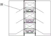
参照图1、图13,所述分拣机2包括分拣机框架20以及多层分拣输送道21,所述分拣输送道21呈长型结构并按层设置在分拣机框架20内,可以根据实际场地设置为直线型或者弯曲型,其与出口输送道4一一对应并且货物对接,在第一种实施案中,例如图14所示,分拣输送道21与出口输送道4的对接位置为出口输送道4的端部,在第二种实施案例中,如图15所示,分拣输送道21与出口输送道4的对接位置为出口输送道4中部的任意位置。每层分拣输送道21的一侧或两侧沿其长度方向设置有多个格口22,所述格口22与分拣输送道21货物对接。每层分拣输送道21均设置一个往复式小车23,所述往复式小车23可沿分拣输送道21的长度方向往复行走,并与出口输送道4以及格口22货物对接。Referring to FIGS. 1 and 13 , the
现有技术的分拣机也有多层结构的,其内设有小车,小车是通过变轨的方式移动至其他层面,不同小车的移动轨迹必然有重叠的部分,因此分拣时需设定分拣顺序以规避撞车现象的发生,分拣逻辑相对较为复杂。另外,小车由接收货物至格口送出货物之间的路程并非直线的最短距离,而且由于逻辑设定小车需减速甚至停止以规避撞车情况,因此其分拣效率相对较低,本发明则解决了上问题,因此对于本发明而言,往复式小车23输送货物的路程为直线最短距离,而且也无需考虑撞车的现象,在分拣模式上相对于现有技术在效率上得到大幅度提升,从另一个角度考虑,提高往复式小车23在分拣输送道21的移动速度可以在优化的分拣模式基础之上进一步提高分拣效率。The sorting machine in the prior art also has a multi-layer structure, and there are trolleys inside. Sorting order to avoid the occurrence of crashes, sorting logic is relatively complex. In addition, the distance between the trolley from receiving the goods to the delivery of the goods from the grid is not the shortest distance in a straight line, and because the logic sets the trolley to decelerate or even stop to avoid a collision, its sorting efficiency is relatively low, and the present invention solves the problem. Therefore, for the present invention, the distance of the reciprocating
参照图13、16并结合图1,因此进一步的,所述分拣输送道21包括两个平行的轨道211以及传动机构,所述轨道211沿分拣输送道21的长度方向设置,往复式小车23设置在轨道211并由传动机构带动其往复移动,具体的,往复式小车23包括车架231以及分拣承载部232,所述车架231底部安装有四个行走在轨道211的行走轮2311,相比现有技术行走时摩擦阻力小,可实现往复式小车23沿轨道211高速行走。所述传动机构包括同步带241、两个传动轴242以及电机243,两个传动轴242分别设置在分拣输送道21的两个端部,所述同步带241沿分拣输送道21长度方向设置,其由两个所述传动轴242传动连接,其中一个传动轴242由电机243驱动,所述往复式小车23的车架231与同步带241固定连接。13 and 16 in combination with FIG. 1, further, the sorting
进一步的,所述同步带241是断开的,并且其宽度小于车架231的宽度,所述车架231的前端以及后端分别固定连接所述同步带241断开的两端,具体的,所述车架231的前端以及后端分别设置有夹块2312用以夹持固定同步带241的两端,这种设置方式安装相对较为方便,另外便于调节同步带241的张紧度,因此在实际应用时时对同步带241的长度计算不需要太精确,通过微调即可解决,便于维护或更换往复式小车23。Further, the
另外,为提高往复式小车23在轨道211行走的稳定性,在所述车架231的底部对应每个轨道211分别至少安装一个导向轮2313,所述导向轮2313与对应的轨道211的内侧面滑动配合,优选各安装两个导向轮2313,四个导向轮2313的位置一一对应四个行走轮2311。In addition, in order to improve the walking stability of the reciprocating
所述分拣承载部232设置为可双向运行的皮带机,并且皮带机的输送方向垂直于往复式小车23的行走方向,当往复式小车23行走并停至对应的格口22时,皮带机启动运行将装载的货物推送至对应的格口22完成货物对接,另外皮带机由设置在分拣输送道21的拖链(图中未显示)供电。The sorting and carrying
考虑到本发明的往复式小车23其行走速度较快,在启动或停止时的惯性也相对较大,为避免货物由于惯性从分拣承载部232脱落,往复式小车23的车架231在前端以及后端分别设置有高于分拣承载部232的挡板2314,两个挡板2314将货物限制在分流承载部132的装载范围内,即可避免上述情况发生。Considering that the reciprocating
对于格口22,在第一种实施案例中,如图17所示,位于分拣输送道同侧且互为上下位置关系的多个所述格口22分别对应不同目的地,应对一般分拣情况。在第二种实施案例中,如图18所示,位于分拣输送道同侧且互为上下位置关系的多个所述格口22对应相同目的地,这种方式可以提高大批同目的地货物的分拣效率。As for the
最后应说明的是:以上实施案例仅用以说明本发明的技术方案,而非对其限制;尽管参照前述实施案例对本发明进行了详细的说明,本领域的普通技术人员应当理解:其依然可以对前述各实施案例所记载的技术方案进行修改,或者对其中部分技术特征进行等同替换;而这些修改或者替换,并不使相应技术方案的本质脱离本发明各实施案例技术方案的范围。Finally, it should be noted that the above implementation cases are only used to illustrate the technical solutions of the present invention, but not to limit them; although the present invention has been described in detail with reference to the foregoing implementation cases, those of ordinary skill in the art should understand that it can still be Modifications are made to the technical solutions recorded in the foregoing embodiments, or equivalent replacements are made to some of the technical features; and these modifications or replacements do not make the essence of the corresponding technical solutions depart from the scope of the technical solutions of the embodiments of the present invention.
Claims (10)
Translated fromChinesePriority Applications (1)
| Application Number | Priority Date | Filing Date | Title |
|---|---|---|---|
| CN202010758402.3ACN111977551B (en) | 2020-07-31 | 2020-07-31 | A hoist trolley and a continuous hoist |
Applications Claiming Priority (1)
| Application Number | Priority Date | Filing Date | Title |
|---|---|---|---|
| CN202010758402.3ACN111977551B (en) | 2020-07-31 | 2020-07-31 | A hoist trolley and a continuous hoist |
Publications (2)
| Publication Number | Publication Date |
|---|---|
| CN111977551Atrue CN111977551A (en) | 2020-11-24 |
| CN111977551B CN111977551B (en) | 2025-05-16 |
Family
ID=73444862
Family Applications (1)
| Application Number | Title | Priority Date | Filing Date |
|---|---|---|---|
| CN202010758402.3AActiveCN111977551B (en) | 2020-07-31 | 2020-07-31 | A hoist trolley and a continuous hoist |
Country Status (1)
| Country | Link |
|---|---|
| CN (1) | CN111977551B (en) |
Cited By (1)
| Publication number | Priority date | Publication date | Assignee | Title |
|---|---|---|---|---|
| CN116750503A (en)* | 2023-01-05 | 2023-09-15 | 宁国恒基伟业建材有限公司 | Gypsum board stacking and transporting equipment |
Citations (6)
| Publication number | Priority date | Publication date | Assignee | Title |
|---|---|---|---|---|
| CN1970408A (en)* | 2006-12-07 | 2007-05-30 | 昆明欧迈科技有限公司 | Transfer apparatus for material circulation and lifting |
| CN102730370A (en)* | 2012-07-13 | 2012-10-17 | 湖州双力自动化科技装备有限公司 | Chain type vertical continuous lifting machine |
| CN103950675A (en)* | 2014-04-04 | 2014-07-30 | 无锡普智联科高新技术有限公司 | Logistics storage system capable of improving cargo sorting speed |
| CN205891895U (en)* | 2016-06-29 | 2017-01-18 | 浙江德马科技股份有限公司 | Vertical elevator sprocket device |
| CN111891643A (en)* | 2020-07-31 | 2020-11-06 | 浙江德马科技股份有限公司 | A power supply mechanism for a continuous hoist |
| CN213294552U (en)* | 2020-07-31 | 2021-05-28 | 浙江德马科技股份有限公司 | Elevator trolley and continuous elevator |
- 2020
- 2020-07-31CNCN202010758402.3Apatent/CN111977551B/enactiveActive
Patent Citations (6)
| Publication number | Priority date | Publication date | Assignee | Title |
|---|---|---|---|---|
| CN1970408A (en)* | 2006-12-07 | 2007-05-30 | 昆明欧迈科技有限公司 | Transfer apparatus for material circulation and lifting |
| CN102730370A (en)* | 2012-07-13 | 2012-10-17 | 湖州双力自动化科技装备有限公司 | Chain type vertical continuous lifting machine |
| CN103950675A (en)* | 2014-04-04 | 2014-07-30 | 无锡普智联科高新技术有限公司 | Logistics storage system capable of improving cargo sorting speed |
| CN205891895U (en)* | 2016-06-29 | 2017-01-18 | 浙江德马科技股份有限公司 | Vertical elevator sprocket device |
| CN111891643A (en)* | 2020-07-31 | 2020-11-06 | 浙江德马科技股份有限公司 | A power supply mechanism for a continuous hoist |
| CN213294552U (en)* | 2020-07-31 | 2021-05-28 | 浙江德马科技股份有限公司 | Elevator trolley and continuous elevator |
Cited By (2)
| Publication number | Priority date | Publication date | Assignee | Title |
|---|---|---|---|---|
| CN116750503A (en)* | 2023-01-05 | 2023-09-15 | 宁国恒基伟业建材有限公司 | Gypsum board stacking and transporting equipment |
| CN116750503B (en)* | 2023-01-05 | 2024-07-19 | 宁国恒基伟业建材有限公司 | Gypsum board stacking and transporting equipment |
Also Published As
| Publication number | Publication date |
|---|---|
| CN111977551B (en) | 2025-05-16 |
Similar Documents
| Publication | Publication Date | Title |
|---|---|---|
| CN103419794B (en) | Article transport facility | |
| KR101943928B1 (en) | Article transport facility | |
| CN102341326B (en) | Device and method for transferring goods between conveyors | |
| CN105358459B (en) | Pallet trucks and pallet sorting equipment | |
| EP3046801A1 (en) | Linear motor transport for packaging and other uses | |
| CN113830485B (en) | Loading and unloading equipment fixed on the rack | |
| CN112340336A (en) | Sorting equipment and sorting method | |
| KR20140087293A (en) | Carrier and overhead hoist system including the same | |
| US7959396B2 (en) | Automated warehouse and method for controlling stacker crane in automated warehouse | |
| CN111977551A (en) | Elevator trolley and continuous elevator | |
| PL181835B1 (en) | Load hadling system conveyor | |
| US6851543B2 (en) | Conveying machine | |
| CN111891643A (en) | A power supply mechanism for a continuous hoist | |
| CN213294552U (en) | Elevator trolley and continuous elevator | |
| CN212474933U (en) | Power supply mechanism of continuous elevator | |
| CN112058674A (en) | Multilayer letter sorting assembly | |
| CN213293621U (en) | Sorting machine | |
| CN213287696U (en) | Multilayer letter sorting assembly | |
| US12280959B2 (en) | Carrier basket transporter with self-damping carrier basket pivot connection | |
| CN112721722A (en) | Rotation type battery replacement station and battery replacement method in rotation | |
| CN112158509B (en) | Intelligent warehouse access system and method | |
| US20230192403A1 (en) | Article sorting device | |
| KR20230099435A (en) | freight sorting device including a plurality of wheel sorters | |
| JP6507728B2 (en) | Lifting and conveying device | |
| US20250206547A1 (en) | Conveyor track and pallet for a conveyor track |
Legal Events
| Date | Code | Title | Description |
|---|---|---|---|
| PB01 | Publication | ||
| PB01 | Publication | ||
| SE01 | Entry into force of request for substantive examination | ||
| SE01 | Entry into force of request for substantive examination | ||
| CB02 | Change of applicant information | ||
| CB02 | Change of applicant information | Address after:313023 shangqiang Industrial Park, Daixi Town, Wuxing District, Huzhou City, Zhejiang Province Applicant after:Dema Technology Group Co.,Ltd. Applicant after:SHANGHAI DAMON LOGISTICS TECHNOLOGY Co.,Ltd. Address before:313023 shangqiang Industrial Park, Daixi Town, Wuxing District, Huzhou City, Zhejiang Province Applicant before:ZHEJIANG DAMON TECHNOLOGY Co.,Ltd. Applicant before:SHANGHAI DAMON LOGISTICS TECHNOLOGY Co.,Ltd. | |
| GR01 | Patent grant | ||
| GR01 | Patent grant |