CN111973849B - Oxygen concentrator with sieve bed bypass and control method thereof - Google Patents
Oxygen concentrator with sieve bed bypass and control method thereofDownload PDFInfo
- Publication number
- CN111973849B CN111973849BCN202010443845.3ACN202010443845ACN111973849BCN 111973849 BCN111973849 BCN 111973849BCN 202010443845 ACN202010443845 ACN 202010443845ACN 111973849 BCN111973849 BCN 111973849B
- Authority
- CN
- China
- Prior art keywords
- flow
- compressor
- ventilator
- oxygen
- patient
- Prior art date
- Legal status (The legal status is an assumption and is not a legal conclusion. Google has not performed a legal analysis and makes no representation as to the accuracy of the status listed.)
- Active
Links
Images


Classifications
- A—HUMAN NECESSITIES
- A61—MEDICAL OR VETERINARY SCIENCE; HYGIENE
- A61M—DEVICES FOR INTRODUCING MEDIA INTO, OR ONTO, THE BODY; DEVICES FOR TRANSDUCING BODY MEDIA OR FOR TAKING MEDIA FROM THE BODY; DEVICES FOR PRODUCING OR ENDING SLEEP OR STUPOR
- A61M16/00—Devices for influencing the respiratory system of patients by gas treatment, e.g. ventilators; Tracheal tubes
- A61M16/10—Preparation of respiratory gases or vapours
- A61M16/1005—Preparation of respiratory gases or vapours with O2 features or with parameter measurement
- A61M16/101—Preparation of respiratory gases or vapours with O2 features or with parameter measurement using an oxygen concentrator
- B—PERFORMING OPERATIONS; TRANSPORTING
- B01—PHYSICAL OR CHEMICAL PROCESSES OR APPARATUS IN GENERAL
- B01D—SEPARATION
- B01D53/00—Separation of gases or vapours; Recovering vapours of volatile solvents from gases; Chemical or biological purification of waste gases, e.g. engine exhaust gases, smoke, fumes, flue gases, aerosols
- B01D53/02—Separation of gases or vapours; Recovering vapours of volatile solvents from gases; Chemical or biological purification of waste gases, e.g. engine exhaust gases, smoke, fumes, flue gases, aerosols by adsorption, e.g. preparative gas chromatography
- B01D53/04—Separation of gases or vapours; Recovering vapours of volatile solvents from gases; Chemical or biological purification of waste gases, e.g. engine exhaust gases, smoke, fumes, flue gases, aerosols by adsorption, e.g. preparative gas chromatography with stationary adsorbents
- B01D53/047—Pressure swing adsorption
- B01D53/053—Pressure swing adsorption with storage or buffer vessel
- A—HUMAN NECESSITIES
- A61—MEDICAL OR VETERINARY SCIENCE; HYGIENE
- A61M—DEVICES FOR INTRODUCING MEDIA INTO, OR ONTO, THE BODY; DEVICES FOR TRANSDUCING BODY MEDIA OR FOR TAKING MEDIA FROM THE BODY; DEVICES FOR PRODUCING OR ENDING SLEEP OR STUPOR
- A61M16/00—Devices for influencing the respiratory system of patients by gas treatment, e.g. ventilators; Tracheal tubes
- A61M16/0003—Accessories therefor, e.g. sensors, vibrators, negative pressure
- A—HUMAN NECESSITIES
- A61—MEDICAL OR VETERINARY SCIENCE; HYGIENE
- A61M—DEVICES FOR INTRODUCING MEDIA INTO, OR ONTO, THE BODY; DEVICES FOR TRANSDUCING BODY MEDIA OR FOR TAKING MEDIA FROM THE BODY; DEVICES FOR PRODUCING OR ENDING SLEEP OR STUPOR
- A61M16/00—Devices for influencing the respiratory system of patients by gas treatment, e.g. ventilators; Tracheal tubes
- A61M16/0057—Pumps therefor
- A61M16/006—Tidal volume membrane pumps
- A—HUMAN NECESSITIES
- A61—MEDICAL OR VETERINARY SCIENCE; HYGIENE
- A61M—DEVICES FOR INTRODUCING MEDIA INTO, OR ONTO, THE BODY; DEVICES FOR TRANSDUCING BODY MEDIA OR FOR TAKING MEDIA FROM THE BODY; DEVICES FOR PRODUCING OR ENDING SLEEP OR STUPOR
- A61M16/00—Devices for influencing the respiratory system of patients by gas treatment, e.g. ventilators; Tracheal tubes
- A61M16/0057—Pumps therefor
- A61M16/0063—Compressors
- A—HUMAN NECESSITIES
- A61—MEDICAL OR VETERINARY SCIENCE; HYGIENE
- A61M—DEVICES FOR INTRODUCING MEDIA INTO, OR ONTO, THE BODY; DEVICES FOR TRANSDUCING BODY MEDIA OR FOR TAKING MEDIA FROM THE BODY; DEVICES FOR PRODUCING OR ENDING SLEEP OR STUPOR
- A61M16/00—Devices for influencing the respiratory system of patients by gas treatment, e.g. ventilators; Tracheal tubes
- A61M16/021—Devices for influencing the respiratory system of patients by gas treatment, e.g. ventilators; Tracheal tubes operated by electrical means
- A61M16/022—Control means therefor
- A61M16/024—Control means therefor including calculation means, e.g. using a processor
- A—HUMAN NECESSITIES
- A61—MEDICAL OR VETERINARY SCIENCE; HYGIENE
- A61M—DEVICES FOR INTRODUCING MEDIA INTO, OR ONTO, THE BODY; DEVICES FOR TRANSDUCING BODY MEDIA OR FOR TAKING MEDIA FROM THE BODY; DEVICES FOR PRODUCING OR ENDING SLEEP OR STUPOR
- A61M16/00—Devices for influencing the respiratory system of patients by gas treatment, e.g. ventilators; Tracheal tubes
- A61M16/10—Preparation of respiratory gases or vapours
- A61M16/1005—Preparation of respiratory gases or vapours with O2 features or with parameter measurement
- A—HUMAN NECESSITIES
- A61—MEDICAL OR VETERINARY SCIENCE; HYGIENE
- A61M—DEVICES FOR INTRODUCING MEDIA INTO, OR ONTO, THE BODY; DEVICES FOR TRANSDUCING BODY MEDIA OR FOR TAKING MEDIA FROM THE BODY; DEVICES FOR PRODUCING OR ENDING SLEEP OR STUPOR
- A61M16/00—Devices for influencing the respiratory system of patients by gas treatment, e.g. ventilators; Tracheal tubes
- A61M16/10—Preparation of respiratory gases or vapours
- A61M16/12—Preparation of respiratory gases or vapours by mixing different gases
- A61M16/122—Preparation of respiratory gases or vapours by mixing different gases with dilution
- A61M16/125—Diluting primary gas with ambient air
- A—HUMAN NECESSITIES
- A61—MEDICAL OR VETERINARY SCIENCE; HYGIENE
- A61M—DEVICES FOR INTRODUCING MEDIA INTO, OR ONTO, THE BODY; DEVICES FOR TRANSDUCING BODY MEDIA OR FOR TAKING MEDIA FROM THE BODY; DEVICES FOR PRODUCING OR ENDING SLEEP OR STUPOR
- A61M16/00—Devices for influencing the respiratory system of patients by gas treatment, e.g. ventilators; Tracheal tubes
- A61M16/20—Valves specially adapted to medical respiratory devices
- A61M16/201—Controlled valves
- A61M16/202—Controlled valves electrically actuated
- B—PERFORMING OPERATIONS; TRANSPORTING
- B01—PHYSICAL OR CHEMICAL PROCESSES OR APPARATUS IN GENERAL
- B01D—SEPARATION
- B01D53/00—Separation of gases or vapours; Recovering vapours of volatile solvents from gases; Chemical or biological purification of waste gases, e.g. engine exhaust gases, smoke, fumes, flue gases, aerosols
- B01D53/02—Separation of gases or vapours; Recovering vapours of volatile solvents from gases; Chemical or biological purification of waste gases, e.g. engine exhaust gases, smoke, fumes, flue gases, aerosols by adsorption, e.g. preparative gas chromatography
- B01D53/04—Separation of gases or vapours; Recovering vapours of volatile solvents from gases; Chemical or biological purification of waste gases, e.g. engine exhaust gases, smoke, fumes, flue gases, aerosols by adsorption, e.g. preparative gas chromatography with stationary adsorbents
- B01D53/0407—Constructional details of adsorbing systems
- B—PERFORMING OPERATIONS; TRANSPORTING
- B01—PHYSICAL OR CHEMICAL PROCESSES OR APPARATUS IN GENERAL
- B01D—SEPARATION
- B01D53/00—Separation of gases or vapours; Recovering vapours of volatile solvents from gases; Chemical or biological purification of waste gases, e.g. engine exhaust gases, smoke, fumes, flue gases, aerosols
- B01D53/02—Separation of gases or vapours; Recovering vapours of volatile solvents from gases; Chemical or biological purification of waste gases, e.g. engine exhaust gases, smoke, fumes, flue gases, aerosols by adsorption, e.g. preparative gas chromatography
- B01D53/04—Separation of gases or vapours; Recovering vapours of volatile solvents from gases; Chemical or biological purification of waste gases, e.g. engine exhaust gases, smoke, fumes, flue gases, aerosols by adsorption, e.g. preparative gas chromatography with stationary adsorbents
- B01D53/047—Pressure swing adsorption
- A—HUMAN NECESSITIES
- A61—MEDICAL OR VETERINARY SCIENCE; HYGIENE
- A61M—DEVICES FOR INTRODUCING MEDIA INTO, OR ONTO, THE BODY; DEVICES FOR TRANSDUCING BODY MEDIA OR FOR TAKING MEDIA FROM THE BODY; DEVICES FOR PRODUCING OR ENDING SLEEP OR STUPOR
- A61M16/00—Devices for influencing the respiratory system of patients by gas treatment, e.g. ventilators; Tracheal tubes
- A61M16/10—Preparation of respiratory gases or vapours
- A61M16/105—Filters
- A—HUMAN NECESSITIES
- A61—MEDICAL OR VETERINARY SCIENCE; HYGIENE
- A61M—DEVICES FOR INTRODUCING MEDIA INTO, OR ONTO, THE BODY; DEVICES FOR TRANSDUCING BODY MEDIA OR FOR TAKING MEDIA FROM THE BODY; DEVICES FOR PRODUCING OR ENDING SLEEP OR STUPOR
- A61M16/00—Devices for influencing the respiratory system of patients by gas treatment, e.g. ventilators; Tracheal tubes
- A61M16/20—Valves specially adapted to medical respiratory devices
- A61M16/201—Controlled valves
- A61M16/202—Controlled valves electrically actuated
- A61M16/203—Proportional
- A—HUMAN NECESSITIES
- A61—MEDICAL OR VETERINARY SCIENCE; HYGIENE
- A61M—DEVICES FOR INTRODUCING MEDIA INTO, OR ONTO, THE BODY; DEVICES FOR TRANSDUCING BODY MEDIA OR FOR TAKING MEDIA FROM THE BODY; DEVICES FOR PRODUCING OR ENDING SLEEP OR STUPOR
- A61M16/00—Devices for influencing the respiratory system of patients by gas treatment, e.g. ventilators; Tracheal tubes
- A61M16/20—Valves specially adapted to medical respiratory devices
- A61M16/208—Non-controlled one-way valves, e.g. exhalation, check, pop-off non-rebreathing valves
- A—HUMAN NECESSITIES
- A61—MEDICAL OR VETERINARY SCIENCE; HYGIENE
- A61M—DEVICES FOR INTRODUCING MEDIA INTO, OR ONTO, THE BODY; DEVICES FOR TRANSDUCING BODY MEDIA OR FOR TAKING MEDIA FROM THE BODY; DEVICES FOR PRODUCING OR ENDING SLEEP OR STUPOR
- A61M16/00—Devices for influencing the respiratory system of patients by gas treatment, e.g. ventilators; Tracheal tubes
- A61M16/0003—Accessories therefor, e.g. sensors, vibrators, negative pressure
- A61M2016/0027—Accessories therefor, e.g. sensors, vibrators, negative pressure pressure meter
- A—HUMAN NECESSITIES
- A61—MEDICAL OR VETERINARY SCIENCE; HYGIENE
- A61M—DEVICES FOR INTRODUCING MEDIA INTO, OR ONTO, THE BODY; DEVICES FOR TRANSDUCING BODY MEDIA OR FOR TAKING MEDIA FROM THE BODY; DEVICES FOR PRODUCING OR ENDING SLEEP OR STUPOR
- A61M16/00—Devices for influencing the respiratory system of patients by gas treatment, e.g. ventilators; Tracheal tubes
- A61M16/0003—Accessories therefor, e.g. sensors, vibrators, negative pressure
- A61M2016/003—Accessories therefor, e.g. sensors, vibrators, negative pressure with a flowmeter
- A61M2016/0033—Accessories therefor, e.g. sensors, vibrators, negative pressure with a flowmeter electrical
- A61M2016/0039—Accessories therefor, e.g. sensors, vibrators, negative pressure with a flowmeter electrical in the inspiratory circuit
- A—HUMAN NECESSITIES
- A61—MEDICAL OR VETERINARY SCIENCE; HYGIENE
- A61M—DEVICES FOR INTRODUCING MEDIA INTO, OR ONTO, THE BODY; DEVICES FOR TRANSDUCING BODY MEDIA OR FOR TAKING MEDIA FROM THE BODY; DEVICES FOR PRODUCING OR ENDING SLEEP OR STUPOR
- A61M16/00—Devices for influencing the respiratory system of patients by gas treatment, e.g. ventilators; Tracheal tubes
- A61M16/10—Preparation of respiratory gases or vapours
- A61M16/1005—Preparation of respiratory gases or vapours with O2 features or with parameter measurement
- A61M2016/102—Measuring a parameter of the content of the delivered gas
- A61M2016/1025—Measuring a parameter of the content of the delivered gas the O2 concentration
- A—HUMAN NECESSITIES
- A61—MEDICAL OR VETERINARY SCIENCE; HYGIENE
- A61M—DEVICES FOR INTRODUCING MEDIA INTO, OR ONTO, THE BODY; DEVICES FOR TRANSDUCING BODY MEDIA OR FOR TAKING MEDIA FROM THE BODY; DEVICES FOR PRODUCING OR ENDING SLEEP OR STUPOR
- A61M2202/00—Special media to be introduced, removed or treated
- A61M2202/02—Gases
- A61M2202/0208—Oxygen
- A—HUMAN NECESSITIES
- A61—MEDICAL OR VETERINARY SCIENCE; HYGIENE
- A61M—DEVICES FOR INTRODUCING MEDIA INTO, OR ONTO, THE BODY; DEVICES FOR TRANSDUCING BODY MEDIA OR FOR TAKING MEDIA FROM THE BODY; DEVICES FOR PRODUCING OR ENDING SLEEP OR STUPOR
- A61M2202/00—Special media to be introduced, removed or treated
- A61M2202/02—Gases
- A61M2202/0266—Nitrogen (N)
- A—HUMAN NECESSITIES
- A61—MEDICAL OR VETERINARY SCIENCE; HYGIENE
- A61M—DEVICES FOR INTRODUCING MEDIA INTO, OR ONTO, THE BODY; DEVICES FOR TRANSDUCING BODY MEDIA OR FOR TAKING MEDIA FROM THE BODY; DEVICES FOR PRODUCING OR ENDING SLEEP OR STUPOR
- A61M2205/00—General characteristics of the apparatus
- A61M2205/33—Controlling, regulating or measuring
- A61M2205/3331—Pressure; Flow
- A61M2205/3334—Measuring or controlling the flow rate
- A—HUMAN NECESSITIES
- A61—MEDICAL OR VETERINARY SCIENCE; HYGIENE
- A61M—DEVICES FOR INTRODUCING MEDIA INTO, OR ONTO, THE BODY; DEVICES FOR TRANSDUCING BODY MEDIA OR FOR TAKING MEDIA FROM THE BODY; DEVICES FOR PRODUCING OR ENDING SLEEP OR STUPOR
- A61M2205/00—General characteristics of the apparatus
- A61M2205/33—Controlling, regulating or measuring
- A61M2205/3331—Pressure; Flow
- A61M2205/3337—Controlling, regulating pressure or flow by means of a valve by-passing a pump
- A—HUMAN NECESSITIES
- A61—MEDICAL OR VETERINARY SCIENCE; HYGIENE
- A61M—DEVICES FOR INTRODUCING MEDIA INTO, OR ONTO, THE BODY; DEVICES FOR TRANSDUCING BODY MEDIA OR FOR TAKING MEDIA FROM THE BODY; DEVICES FOR PRODUCING OR ENDING SLEEP OR STUPOR
- A61M2205/00—General characteristics of the apparatus
- A61M2205/33—Controlling, regulating or measuring
- A61M2205/3379—Masses, volumes, levels of fluids in reservoirs, flow rates
- A—HUMAN NECESSITIES
- A61—MEDICAL OR VETERINARY SCIENCE; HYGIENE
- A61M—DEVICES FOR INTRODUCING MEDIA INTO, OR ONTO, THE BODY; DEVICES FOR TRANSDUCING BODY MEDIA OR FOR TAKING MEDIA FROM THE BODY; DEVICES FOR PRODUCING OR ENDING SLEEP OR STUPOR
- A61M2205/00—General characteristics of the apparatus
- A61M2205/35—Communication
- A61M2205/3546—Range
- A61M2205/3561—Range local, e.g. within room or hospital
- A—HUMAN NECESSITIES
- A61—MEDICAL OR VETERINARY SCIENCE; HYGIENE
- A61M—DEVICES FOR INTRODUCING MEDIA INTO, OR ONTO, THE BODY; DEVICES FOR TRANSDUCING BODY MEDIA OR FOR TAKING MEDIA FROM THE BODY; DEVICES FOR PRODUCING OR ENDING SLEEP OR STUPOR
- A61M2205/00—General characteristics of the apparatus
- A61M2205/35—Communication
- A61M2205/3576—Communication with non implanted data transmission devices, e.g. using external transmitter or receiver
- A61M2205/3592—Communication with non implanted data transmission devices, e.g. using external transmitter or receiver using telemetric means, e.g. radio or optical transmission
- A—HUMAN NECESSITIES
- A61—MEDICAL OR VETERINARY SCIENCE; HYGIENE
- A61M—DEVICES FOR INTRODUCING MEDIA INTO, OR ONTO, THE BODY; DEVICES FOR TRANSDUCING BODY MEDIA OR FOR TAKING MEDIA FROM THE BODY; DEVICES FOR PRODUCING OR ENDING SLEEP OR STUPOR
- A61M2205/00—General characteristics of the apparatus
- A61M2205/50—General characteristics of the apparatus with microprocessors or computers
- A61M2205/502—User interfaces, e.g. screens or keyboards
- A—HUMAN NECESSITIES
- A61—MEDICAL OR VETERINARY SCIENCE; HYGIENE
- A61M—DEVICES FOR INTRODUCING MEDIA INTO, OR ONTO, THE BODY; DEVICES FOR TRANSDUCING BODY MEDIA OR FOR TAKING MEDIA FROM THE BODY; DEVICES FOR PRODUCING OR ENDING SLEEP OR STUPOR
- A61M2205/00—General characteristics of the apparatus
- A61M2205/75—General characteristics of the apparatus with filters
- A—HUMAN NECESSITIES
- A61—MEDICAL OR VETERINARY SCIENCE; HYGIENE
- A61M—DEVICES FOR INTRODUCING MEDIA INTO, OR ONTO, THE BODY; DEVICES FOR TRANSDUCING BODY MEDIA OR FOR TAKING MEDIA FROM THE BODY; DEVICES FOR PRODUCING OR ENDING SLEEP OR STUPOR
- A61M2205/00—General characteristics of the apparatus
- A61M2205/82—Internal energy supply devices
- A61M2205/8206—Internal energy supply devices battery-operated
- A—HUMAN NECESSITIES
- A61—MEDICAL OR VETERINARY SCIENCE; HYGIENE
- A61M—DEVICES FOR INTRODUCING MEDIA INTO, OR ONTO, THE BODY; DEVICES FOR TRANSDUCING BODY MEDIA OR FOR TAKING MEDIA FROM THE BODY; DEVICES FOR PRODUCING OR ENDING SLEEP OR STUPOR
- A61M2209/00—Ancillary equipment
- A61M2209/08—Supports for equipment
- A61M2209/084—Supporting bases, stands for equipment
- A61M2209/086—Docking stations
- B—PERFORMING OPERATIONS; TRANSPORTING
- B01—PHYSICAL OR CHEMICAL PROCESSES OR APPARATUS IN GENERAL
- B01D—SEPARATION
- B01D2253/00—Adsorbents used in seperation treatment of gases and vapours
- B01D2253/10—Inorganic adsorbents
- B01D2253/106—Silica or silicates
- B01D2253/108—Zeolites
- B—PERFORMING OPERATIONS; TRANSPORTING
- B01—PHYSICAL OR CHEMICAL PROCESSES OR APPARATUS IN GENERAL
- B01D—SEPARATION
- B01D2256/00—Main component in the product gas stream after treatment
- B01D2256/12—Oxygen
- B—PERFORMING OPERATIONS; TRANSPORTING
- B01—PHYSICAL OR CHEMICAL PROCESSES OR APPARATUS IN GENERAL
- B01D—SEPARATION
- B01D2257/00—Components to be removed
- B01D2257/10—Single element gases other than halogens
- B01D2257/102—Nitrogen
- B—PERFORMING OPERATIONS; TRANSPORTING
- B01—PHYSICAL OR CHEMICAL PROCESSES OR APPARATUS IN GENERAL
- B01D—SEPARATION
- B01D2259/00—Type of treatment
- B01D2259/45—Gas separation or purification devices adapted for specific applications
- B01D2259/4533—Gas separation or purification devices adapted for specific applications for medical purposes
Landscapes
- Health & Medical Sciences (AREA)
- Engineering & Computer Science (AREA)
- Emergency Medicine (AREA)
- General Health & Medical Sciences (AREA)
- Veterinary Medicine (AREA)
- Biomedical Technology (AREA)
- Heart & Thoracic Surgery (AREA)
- Hematology (AREA)
- Life Sciences & Earth Sciences (AREA)
- Animal Behavior & Ethology (AREA)
- Pulmonology (AREA)
- Public Health (AREA)
- Anesthesiology (AREA)
- Chemical & Material Sciences (AREA)
- Analytical Chemistry (AREA)
- General Chemical & Material Sciences (AREA)
- Oil, Petroleum & Natural Gas (AREA)
- Chemical Kinetics & Catalysis (AREA)
- Separation Of Gases By Adsorption (AREA)
- Oxygen, Ozone, And Oxides In General (AREA)
Abstract
Description
Translated fromChinese背景background
1.发明的技术领域1. Technical field of the invention
本公开总体上涉及氧气浓缩器,并且更具体地,涉及一种氧气浓缩器,该氧气浓缩器被布置为产生高氧气含量的气体,该气体通过呼吸机被输送给患者。The present disclosure relates generally to oxygen concentrators, and more particularly to an oxygen concentrator arranged to produce a high oxygen content gas that is delivered to a patient through a ventilator.
2.相关技术的描述2. Description of Related Technology
广泛的临床状况可能需要某种形式的通气治疗,由此,从呼吸机到患者气道的加压气体流有助于患者的呼吸功。这些状况可能包括低氧血症、各种形式的呼吸功能不全以及气道失调。也有需要通气治疗的非呼吸道和非气道疾病,例如充血性心力衰竭和神经肌肉疾病。A wide range of clinical conditions may require some form of ventilation therapy, whereby a flow of pressurized gas from a ventilator to the patient's airway assists the patient's work of breathing. These conditions may include hypoxemia, various forms of respiratory insufficiency, and airway disorders. There are also non-respiratory and non-airway diseases that require ventilation therapy, such as congestive heart failure and neuromuscular diseases.
为了改善许多需要长期通气治疗的患者的生活质量,已经开发了小型化和便携式的通气系统。这些系统中的某些系统(例如Breathe Technologies,Inc.的
许多上述临床状况和其他临床状况也可能需要补充氧气治疗或从中受益,通过额外的氧气的存在来增加引入患者气道的气体,从而使患者吸入氧气含量高于大气浓度(湿度为0%时为20.9%)的气体。补充氧气治疗涉及患者从氧气源(通常为压缩氧气瓶或低温氧气瓶,或氧气发生器)接收补充氧气。多年来,希望移动的患者依靠氧气瓶。然而,近年来,电池技术的小型化和改进已带来了便携式氧气浓缩器的发展。Many of the above clinical conditions and others may also require or benefit from supplemental oxygen therapy, which augments the gas introduced into the patient's airways with the presence of additional oxygen, resulting in the patient breathing a gas with an oxygen content greater than that of atmospheric concentration (20.9% at 0% humidity). Supplemental oxygen therapy involves the patient receiving supplemental oxygen from an oxygen source, typically a compressed or cryogenic oxygen cylinder, or an oxygen generator. For many years, patients who wished to be mobile relied on oxygen cylinders. However, in recent years, miniaturization and improvements in battery technology have led to the development of portable oxygen concentrators.
便携式氧气浓缩器通常通过变压吸附(PSA)来操作,其中环境空气被压缩机加压并通过吸附筛床。筛床通常由沸石形成,当在高压下氧气通过时,沸石优先吸附氮。一旦筛床达到其吸附氮的容量,就可以降低压力。压力的降低导致吸附的氮解吸,因此可以将其清除,留下再生的筛床,该筛床再次准备好吸附氮。通过该操作的反复循环,可以产生富氧气体。通常,便携式氧气浓缩器具有至少两个筛床,以便其中一个可以操作,而另一个正在清除氮并排出。如今,典型的便携式氧气浓缩器输出约87%-96%氧气纯度的富氧气体。在当今可以被(尤其是患有呼吸疾病的个人)认为是便携式的现有氧气浓缩器中,通常有两种类型。第一种类型较大且较重,通常能够进行连续流量输送。这种类型的模型的重量通常在5-10kg之间,最大流速约为每分钟5-6升或更小,并且通常配置有轮子和手柄,通常模仿手提箱的外观。第二种类型是较轻的单元,更适合在挎包、手提包或背包中携带或佩戴。这种类型的模型通常重量不到2.5kg,并且通常仅限于最大流速约为每分钟2升或更小的脉冲输送方式。Portable oxygen concentrators typically operate by pressure swing adsorption (PSA), where ambient air is pressurized by a compressor and passed through an adsorbent sieve bed. The sieve bed is typically formed of zeolite, which preferentially adsorbs nitrogen when oxygen is passed through it at high pressure. Once the sieve bed reaches its capacity to adsorb nitrogen, the pressure can be reduced. The reduction in pressure causes the adsorbed nitrogen to desorb, so it can be purged, leaving a regenerated sieve bed that is once again ready to adsorb nitrogen. Through repeated cycles of this operation, oxygen-enriched gas can be produced. Typically, a portable oxygen concentrator has at least two sieve beds so that one of them can operate while the other is purging nitrogen and discharging. Today, a typical portable oxygen concentrator outputs oxygen-enriched gas with an oxygen purity of about 87%-96%. Among the existing oxygen concentrators that can be considered portable today (especially for individuals with respiratory diseases), there are generally two types. The first type is larger and heavier, and is typically capable of continuous flow delivery. Models of this type typically weigh between 5-10kg, have a maximum flow rate of about 5-6 liters per minute or less, and are typically configured with wheels and handles, typically mimicking the appearance of a suitcase. The second type is a lighter unit that is better suited for carrying or wearing in a shoulder bag, handbag or backpack. Models of this type typically weigh less than 2.5kg and are usually limited to pulsed delivery with a maximum flow rate of about 2 liters per minute or less.
便携式氧气浓缩器相对于加压氧气瓶具有实质性的成本和便利性优势,因为加压氧气瓶需要不断地重新填充或更换。另外,便携式氧气浓缩器被认为比加压氧气瓶安全得多。这种安全考虑会对患者的生活质量产生重大影响,因为许多便携式氧气浓缩器已获得美国联邦航空局(FAA)的批准,可供商业航空公司的旅行者使用,而氧气瓶普遍被禁止在商业航班上使用。因此,带有加压氧气瓶的患者必须提前与航空公司进行昂贵且耗时的准备工作,或放弃航空旅行。Portable oxygen concentrators offer substantial cost and convenience advantages over pressurized oxygen cylinders, which need to be constantly refilled or replaced. Additionally, portable oxygen concentrators are considered much safer than pressurized oxygen cylinders. This safety consideration can have a significant impact on a patient's quality of life, as many portable oxygen concentrators are approved by the FAA for use by commercial airline travelers, whereas oxygen cylinders are generally prohibited on commercial flights. As a result, patients with pressurized oxygen cylinders must make costly and time-consuming preparations with the airline in advance or forgo air travel.
对于不需要呼吸工作帮助情况下的患者,仅补充氧气治疗而无需通气治疗可能就足够了。但是,对于许多患者而言,联合通气治疗和补充氧气治疗可能是更理想的治疗方法。在健康的患者中,执行呼吸工作的足够的通气通常在静止状态下需要5-8L/min的分钟通气速率,这在轻度运动中可能会加倍,而在剧烈运动中可能会超过40L/min。患有呼吸系统疾病的患者可能需要更高的速率和更高的瞬时速率。当这些患者在家以外并需要便携性时尤其如此,因为在这些时候,这些患者也经常参与轻度运动。For patients who do not require assistance with the work of breathing, supplemental oxygen therapy alone without ventilation therapy may be sufficient. However, for many patients, combined ventilation therapy and supplemental oxygen therapy may be a more ideal treatment approach. In healthy patients, adequate ventilation to perform the work of breathing typically requires a minute ventilation rate of 5-8 L/min at rest, which may double during mild exercise and may exceed 40 L/min during vigorous exercise. Patients with respiratory disease may require higher rates and higher instantaneous rates. This is especially true when these patients are away from home and require portability, as these patients often also participate in mild exercise at these times.
因此可以看出,在许多情况下,由于在不具有额外的压缩气体源时,现有的便携式氧气浓缩器不能以足够高的压力和/或体积输出气体,从而无法与可穿戴式便携式呼吸机一起使用,因此希望接受这种联合治疗方式的患者受到了很大的限制。因此,当需要最大的便携性时,这些患者必须放弃便携式氧气浓缩器的实质好处,而使用氧气瓶(氧气瓶可以以通气治疗所需的较高压力和流速输出氧气),或者这些患者必须另外携带便携式压缩机,使得便携式氧气浓缩器、便携式压缩机和可穿戴呼吸机连接在一起。It can therefore be seen that in many cases, patients who wish to receive this combined therapy are greatly limited because existing portable oxygen concentrators cannot deliver gas at a sufficiently high pressure and/or volume to be used with a wearable portable ventilator without an additional source of compressed gas. Therefore, when maximum portability is required, these patients must either forgo the substantial benefits of a portable oxygen concentrator and use an oxygen cylinder (which can deliver oxygen at the higher pressure and flow rate required for ventilation therapy), or these patients must additionally carry a portable compressor so that the portable oxygen concentrator, portable compressor, and wearable ventilator are connected together.
试图提供组合的补充氧气/通气系统的现有系统和方法基本上是不足的。例如,美国专利申请公开No.2017/0340851和No.2018/0001048描述了在氧气浓缩器的产物储箱的下游增加蓄能器箱,以用于向机械呼吸机提供更恒定的产物气体流量的所述目的。美国专利申请公开No.2017/0113013描述了使用产物储箱压力和输出流速测量值来确定氧气浓缩器是否与呼吸机流体联接(其特征可在于间歇性地、自发性突发地利用氧气浓缩器的富氧气体)。如果是这样,则控制氧气浓缩器的阀或泵,以增加或降低产物储箱压力或气体流速,以满足呼吸机的供气要求。这样的系统通常可以理解为仅旨在满足呼吸机的过程要求,例如确保产物储箱压力不低于某个阈值。它们没有能力满足接受通气治疗的患者的特定需求。尽管美国专利申请公开No.2017/0113013设想了患者状态指示器的确定,该确定仅基于在浓缩器内执行的测量,且仅相当于粗略的估算。Existing systems and methods that attempt to provide a combined supplemental oxygen/ventilation system are substantially inadequate. For example, U.S. Patent Application Publication Nos. 2017/0340851 and 2018/0001048 describe adding an accumulator tank downstream of the product tank of an oxygen concentrator for the stated purpose of providing a more constant product gas flow to a mechanical ventilator. U.S. Patent Application Publication No. 2017/0113013 describes the use of product tank pressure and output flow rate measurements to determine whether an oxygen concentrator is fluidly coupled to a ventilator (which may be characterized by intermittent, spontaneous bursts of oxygen-enriched gas from an oxygen concentrator). If so, the valve or pump of the oxygen concentrator is controlled to increase or decrease the product tank pressure or gas flow rate to meet the gas supply requirements of the ventilator. Such systems can generally be understood as being intended only to meet the process requirements of the ventilator, such as ensuring that the product tank pressure is not below a certain threshold. They are not capable of meeting the specific needs of patients receiving ventilation therapy. Although U.S. Patent Application Publication No. 2017/0113013 contemplates the determination of a patient status indicator, that determination is based solely on measurements performed within the concentrator and amounts to only a rough estimate.
发明内容Summary of the invention
本公开构思了各种系统、方法和设备,用于克服伴随相关技术的上述缺点。本公开的实施例的一个方面是一种氧气浓缩器,其包括:一个或多个吸附筛床,其能够操作用于从空气中除去氮以在其各自的出口处产生浓缩氧气;产物储箱,其流体地联接到一个或多个吸附筛床的各自的出口;压缩机,其能够操作用于对环境空气加压;一个或多个筛床流动路径,其从压缩机到一个或多个吸附筛床的各自的入口;旁路流动路径,其从压缩机到产物储箱,绕过一个或多个吸附筛床;以及阀单元,其能够操作用于响应于控制信号而选择性地允许来自压缩机的加压环境空气沿着一个或多个筛床流动路径以及沿着旁路流动路径流动。The present disclosure contemplates various systems, methods, and apparatuses for overcoming the above-mentioned shortcomings associated with the related art. One aspect of an embodiment of the present disclosure is an oxygen concentrator comprising: one or more adsorbent sieve beds operable to remove nitrogen from air to produce concentrated oxygen at respective outlets thereof; a product tank fluidly coupled to respective outlets of the one or more adsorbent sieve beds; a compressor operable to pressurize ambient air; one or more sieve bed flow paths from the compressor to respective inlets of the one or more adsorbent sieve beds; a bypass flow path from the compressor to the product tank, bypassing the one or more adsorbent sieve beds; and a valve unit operable to selectively allow pressurized ambient air from the compressor to flow along the one or more sieve bed flow paths and along the bypass flow path in response to a control signal.
阀单元可以包括一个或多个开/关阀,并且阀单元可以通过相对于一个或多个吸附筛床的操作周期选择性地调节一个或多个开/关阀的状态定时,来选择性地允许来自压缩机的加压环境空气沿着一个或多个筛床流动路径以及沿着旁路流动路径流动。The valve unit may include one or more on/off valves, and the valve unit may selectively allow pressurized ambient air from a compressor to flow along the one or more sieve bed flow paths and along the bypass flow path by selectively adjusting the timing of states of the one or more on/off valves relative to an operating cycle of the one or more adsorbent sieve beds.
阀单元可以包括一个或多个比例阀,并且阀单元可以通过选择性地调节到一个或多个比例阀的输入量,来选择性地允许来自压缩机的加压环境空气沿着一个或多个筛床流动路径以及沿着所述旁路流动路径流动。阀单元还可以通过相对于一个或多个吸附筛床的操作周期选择性地调节一个或多个比例阀的状态定时,来选择性地允许来自压缩机的加压环境空气沿着一个或多个筛床流动路径以及沿着旁路流动路径流动。The valve unit may include one or more proportional valves, and the valve unit may selectively allow pressurized ambient air from the compressor to flow along the one or more sieve bed flow paths and along the bypass flow path by selectively adjusting inputs to the one or more proportional valves. The valve unit may also selectively allow pressurized ambient air from the compressor to flow along the one or more sieve bed flow paths and along the bypass flow path by selectively adjusting state timing of the one or more proportional valves relative to an operating cycle of the one or more adsorbent sieve beds.
氧气浓缩器还可以包括控制器,该控制器能够操作用于产生控制信号。由控制器产生的控制信号可以操作阀单元,以维持产物储箱中的预设氧气浓度。控制器可以响应于由流体地联接到产物储箱的出口的呼吸机发出的命令而产生控制信号。The oxygen concentrator may further include a controller operable to generate a control signal. The control signal generated by the controller may operate the valve unit to maintain a preset oxygen concentration in the product tank. The controller may generate the control signal in response to a command issued by a ventilator fluidly coupled to an outlet of the product tank.
本公开的实施例的另一方面是一种包括上述氧气浓缩器和上述呼吸机的系统。呼吸机可以基于用户输入的氧气浓度来计算预设氧气浓度。呼吸机还可以基于所测量的呼吸机的通气气体输出来计算预设氧气浓度。呼吸机还可以基于呼吸机的患者通气接口中的测量压力来计算预设氧气浓度。Another aspect of an embodiment of the present disclosure is a system comprising the above oxygen concentrator and the above ventilator. The ventilator can calculate a preset oxygen concentration based on an oxygen concentration input by a user. The ventilator can also calculate a preset oxygen concentration based on a measured ventilation gas output of the ventilator. The ventilator can also calculate a preset oxygen concentration based on a measured pressure in a patient ventilation interface of the ventilator.
呼吸机可以包括:流量传感器,其用于测量由连接到呼吸机的患者通气接口的一个或多个喷嘴排出的气体的流量;压力传感器,其用于测量患者通气接口中的压力;以及主控制器,其被配置为基于测量流量和测量压力来发出命令。主控制器可以被配置为基于由呼吸机输送的气体和夹带空气的总流量的计算来发出命令,其中由呼吸机输送的气体和夹带空气的总流量为测量流量和测量压力的函数。主控制器可以被配置为基于测量压力与呼吸机输送的气体和夹带空气的总流量的多个测量值的比较来发出命令,其中呼吸机输送的气体和夹带空气的总流量的多个测量值是对应于针对测量流量的患者通气接口中的压力的多个测量值而存储的。主控制器可以被配置为基于测量压力与吸入氧气分数%FiO2的多个测量值的比较来发出命令,其中吸入氧气分数%FiO2的多个测量值是对应于针对测量流量的患者通气接口中的压力的多个测量值而存储的。The ventilator may include: a flow sensor for measuring the flow of gas discharged by one or more nozzles of a patient ventilation interface connected to the ventilator; a pressure sensor for measuring the pressure in the patient ventilation interface; and a main controller configured to issue commands based on the measured flow and the measured pressure. The main controller may be configured to issue commands based on a calculation of the total flow of gas and entrained air delivered by the ventilator, wherein the total flow of gas and entrained air delivered by the ventilator is a function of the measured flow and the measured pressure. The main controller may be configured to issue commands based on a comparison of the measured pressure with a plurality of measurements of the total flow of gas and entrained air delivered by the ventilator, wherein the plurality of measurements of the total flow of gas and entrained air delivered by the ventilator are stored corresponding to a plurality of measurements of pressure in the patient ventilation interface for the measured flow. The main controller may be configured to issue commands based on a comparison of the measured pressure with a plurality of measurements of inspired oxygen fraction %FiO2 , wherein the plurality of measurements of inspired oxygen fraction %FiO2 are stored corresponding to a plurality of measurements of pressure in the patient ventilation interface for the measured flow.
由控制器产生的控制信号可以操作压缩机,以维持产物储箱中的预设氧气浓度。A control signal generated by the controller may operate the compressor to maintain a preset oxygen concentration in the product tank.
本公开的实施例的另一方面是一种氧气浓缩器,其包括:一个或多个吸附筛床,其能够操作用于从空气中除去氮以在其各自的出口处产生浓缩氧气;产物储箱,其流体地联接到一个或多个吸附筛床的各自的出口;压缩机,其能够操作用于对环境空气加压;一个或多个筛床流动路径,其从压缩机到一个或多个吸附筛床的各自的入口;旁路压缩机,其能够操作用于对环境空气加压,该旁路压缩机不同于上述压缩机;旁路流动路径,其从旁路压缩机到产物储箱,绕过一个或多个吸附筛床;以及控制器,其能够操作用于产生控制信号从而控制旁路压缩机,以选择性地允许来自旁路压缩机的加压环境空气沿着旁路流动路径流动。Another aspect of an embodiment of the present disclosure is an oxygen concentrator comprising: one or more adsorbent sieve beds operable to remove nitrogen from air to produce concentrated oxygen at respective outlets thereof; a product tank fluidly coupled to respective outlets of the one or more adsorbent sieve beds; a compressor operable to pressurize ambient air; one or more sieve bed flow paths from the compressor to respective inlets of the one or more adsorbent sieve beds; a bypass compressor operable to pressurize ambient air, the bypass compressor being distinct from the compressor; a bypass flow path from the bypass compressor to the product tank, bypassing the one or more adsorbent sieve beds; and a controller operable to generate a control signal to control the bypass compressor to selectively allow pressurized ambient air from the bypass compressor to flow along the bypass flow path.
本公开的实施例的另一方面是一种氧气浓缩器,其包括:一个或多个吸附筛床,其能够操作用于从空气中除去氮以在其各自的出口处产生浓缩氧气;产物储箱,其流体地联接到一个或多个吸附筛床的各自的出口;压缩机,其能够操作用于对环境空气加压;一个或多个筛床流动路径,其从压缩机到一个或多个吸附筛床的各自的入口;旁路流动路径,其从外部压缩机流体端口到产物储箱,绕过一个或多个吸附筛床;以及控制器,其能够操作用于产生控制信号从而经由外部压缩机信号端口来控制与外部压缩机流体端口流体连接的外部压缩机,该控制信号选择性地允许来自外部压缩机的加压环境空气沿着旁路流动路径流动。Another aspect of an embodiment of the present disclosure is an oxygen concentrator comprising: one or more adsorbent sieve beds operable to remove nitrogen from air to produce concentrated oxygen at respective outlets thereof; a product tank fluidly coupled to respective outlets of the one or more adsorbent sieve beds; a compressor operable to pressurize ambient air; one or more sieve bed flow paths from the compressor to respective inlets of the one or more adsorbent sieve beds; a bypass flow path from an external compressor fluid port to the product tank, bypassing the one or more adsorbent sieve beds; and a controller operable to generate a control signal to control an external compressor fluidly coupled to the external compressor fluid port via an external compressor signal port, the control signal selectively allowing pressurized ambient air from the external compressor to flow along the bypass flow path.
本公开的实施例的另一方面是一种模块化系统,其包括上述氧气浓缩器、容纳该氧气浓缩器的氧气浓缩器模块以及容纳外部压缩机的压缩机模块。氧气浓缩器模块和压缩机模块可以可拆卸地附接以形成单个单元。Another aspect of an embodiment of the present disclosure is a modular system comprising the above oxygen concentrator, an oxygen concentrator module accommodating the oxygen concentrator, and a compressor module accommodating an external compressor. The oxygen concentrator module and the compressor module can be detachably attached to form a single unit.
本公开的实施例的另一方面是一种用于在患者的多个活动水平下控制氧气浓缩器以满足患者的通气和补充氧气需求的方法。该方法可以包括将氧气浓缩器转换成第一配置,其中等于或大于无环境空气的第一部分环境空气与由氧气浓缩器的一个或多个筛床输出的浓缩氧气混合,从而产生具有第一氧气浓度的第一流量的浓缩器输出。该方法还可以包括将氧气浓缩器转换成第二配置,其中大于第一部分的第二部分环境空气与由一个或多个筛床输出的浓缩氧气混合,从而产生具有第二氧气浓度的第二流量的浓缩器输出,其中第二流量大于第一流量,第二氧气浓度小于第一氧气浓度。Another aspect of an embodiment of the present disclosure is a method for controlling an oxygen concentrator to meet ventilation and supplemental oxygen requirements of a patient at multiple activity levels of the patient. The method may include converting the oxygen concentrator to a first configuration, wherein a first portion of ambient air equal to or greater than no ambient air is mixed with concentrated oxygen output by one or more sieve beds of the oxygen concentrator to produce a concentrator output having a first flow rate of a first oxygen concentration. The method may also include converting the oxygen concentrator to a second configuration, wherein a second portion of ambient air greater than the first portion is mixed with concentrated oxygen output by one or more sieve beds to produce a concentrator output having a second flow rate of a second oxygen concentration, wherein the second flow rate is greater than the first flow rate and the second oxygen concentration is less than the first oxygen concentration.
本公开的实施例的另一方面是一种用于在患者的多个活动水平下控制氧气浓缩器以满足患者的通气和补充氧气需求的方法。该方法可以包括将氧气浓缩器转换成第一配置,其中由氧气浓缩器的一个或多个筛床输出的第一部分浓缩氧气气体(第一部分等于或大于无浓缩氧气气体)与环境空气混合,从而产生具有第一氧气浓度的第一流量的浓缩器输出。该方法还可以包括将氧气浓缩器转换成第二配置,其中由一个或多个筛床输出的第二部分浓缩氧气气体(第二部分大于第一部分)与环境空气混合,从而产生具有第二氧气浓度的第二流量的浓缩器输出,其中第二流量小于第一流量,第二氧气浓度大于第一氧气浓度。Another aspect of an embodiment of the present disclosure is a method for controlling an oxygen concentrator to meet ventilation and supplemental oxygen needs of a patient at multiple activity levels of the patient. The method may include converting the oxygen concentrator to a first configuration, wherein a first portion of concentrated oxygen gas (the first portion is equal to or greater than non-concentrated oxygen gas) output by one or more sieve beds of the oxygen concentrator is mixed with ambient air to produce a concentrator output having a first flow rate of a first oxygen concentration. The method may also include converting the oxygen concentrator to a second configuration, wherein a second portion of concentrated oxygen gas (the second portion is greater than the first portion) output by one or more sieve beds is mixed with ambient air to produce a concentrator output having a second flow rate of a second oxygen concentration, wherein the second flow rate is less than the first flow rate and the second oxygen concentration is greater than the first oxygen concentration.
本公开的实施例的另一方面是一种用于计算由呼吸机输送给患者的气体和夹带空气的总流量的方法。该方法可以包括:存储与多个喷嘴几何形状中的每一个相关联的一个或多个常数;测量由连接到呼吸机的患者通气接口的一个或多个喷嘴排出的气体的流量,该一个或多个喷嘴具有与多个喷嘴几何形状中的一个相对应的喷嘴几何形状;测量患者通气接口中的压力;以及基于测量流量、测量压力以及所存储的与一个或多个喷嘴的喷嘴几何形状相关联的一个或多个常数来计算总流量。Another aspect of an embodiment of the present disclosure is a method for calculating the total flow of gas and entrained air delivered to a patient by a ventilator. The method may include: storing one or more constants associated with each of a plurality of nozzle geometries; measuring the flow of gas discharged by one or more nozzles connected to a patient ventilation interface of the ventilator, the one or more nozzles having a nozzle geometry corresponding to one of the plurality of nozzle geometries; measuring the pressure in the patient ventilation interface; and calculating the total flow based on the measured flow, the measured pressure, and the stored one or more constants associated with the nozzle geometry of the one or more nozzles.
该方法还可以包括基于所计算的总流量向氧气浓缩器传输信号。The method may also include transmitting a signal to an oxygen concentrator based on the calculated total flow.
该方法还可以包括通过对所计算的总流量相对于时间进行积分来计算总吸入潮气量。该方法还可以包括基于所计算的总吸入潮气量向氧气浓缩器传输信号。The method may further include calculating a total inspired tidal volume by integrating the calculated total flow with respect to time. The method may further include transmitting a signal to an oxygen concentrator based on the calculated total inspired tidal volume.
该方法还可以包括:通过对测量流量相对于时间进行积分来计算由一个或多个喷嘴排出的气体的吸入潮气量;通过对夹带流量相对于时间进行积分来计算夹带空气的吸入潮气量,夹带流量是所计算的总流量与测量流量之间的差;以及基于由一个或多个喷嘴排出的气体的吸入潮气量和夹带空气的吸入潮气量来计算患者的吸入氧气分数%FiO2。该方法还可以包括基于所计算的%FiO2向氧气浓缩器传输信号。The method may also include calculating an inspired tidal volume of gas expelled by the one or more nozzles by integrating the measured flow rate with respect to time; calculating an inspired tidal volume of entrained air by integrating the entrained flow rate with respect to time, the entrained flow rate being the difference between the calculated total flow rate and the measured flow rate; and calculating an inspired oxygen fraction %FiO2 of the patient based on the inspired tidal volume of gas expelled by the one or more nozzles and the inspired tidal volume of entrained air. The method may also include transmitting a signal to an oxygen concentrator based on the calculated %FiO2 .
对于多个喷嘴几何形状中的每一个,相关联的一个或多个常数被存储在存储器中,该存储器设置在具有该喷嘴几何形状的喷嘴的患者通气接口中。计算总流量可以包括读取存储在连接到呼吸机的患者通气接口中的一个或多个常数。For each of the plurality of nozzle geometries, the associated one or more constants are stored in a memory disposed in a patient ventilation interface of a nozzle having the nozzle geometry. Calculating the total flow may include reading the one or more constants stored in a patient ventilation interface connected to the ventilator.
本公开的实施例的另一方面是一种用于基于由呼吸机输送给患者的气体和夹带空气的总流量来控制氧气浓缩器的方法。该方法可以包括:测量由连接到呼吸机的患者通气接口的一个或多个喷嘴排出的气体的流量;测量患者通气接口中的压力;基于测量流量和测量压力来计算总流量;以及基于所计算的总流量向氧气浓缩器传输信号。Another aspect of an embodiment of the present disclosure is a method for controlling an oxygen concentrator based on a total flow of gas and entrained air delivered to a patient by a ventilator. The method may include: measuring the flow of gas discharged by one or more nozzles connected to a patient ventilation interface of the ventilator; measuring the pressure in the patient ventilation interface; calculating the total flow based on the measured flow and the measured pressure; and transmitting a signal to the oxygen concentrator based on the calculated total flow.
该方法还可以包括通过对所计算的总流量相对于时间进行积分来计算总吸入潮气量。信号的传输可以基于所计算的总吸入潮气量。The method may further include calculating a total inspired tidal volume by integrating the calculated total flow with respect to time. The transmission of the signal may be based on the calculated total inspired tidal volume.
该方法还可以包括:通过对测量流量相对于时间进行积分来计算由一个或多个喷嘴排出的气体的吸入潮气量;通过对夹带流量相对于时间进行积分来计算夹带空气的吸入潮气量,夹带流量是所计算的总流量与测量流量之间的差;以及基于一个或多个喷嘴排出的气体的吸入潮气量和夹带空气的吸入潮气量来计算患者的吸入氧气分数%FiO2。信号的传输可以基于所计算的%FiO2。The method may also include: calculating an inspired tidal volume of gas expelled by the one or more nozzles by integrating the measured flow rate with respect to time; calculating an inspired tidal volume of entrained air by integrating the entrained flow rate with respect to time, the entrained flow rate being the difference between the calculated total flow rate and the measured flow rate; and calculating an inspired oxygen fraction %FiO2 of the patient based on the inspired tidal volume of gas expelled by the one or more nozzles and the inspired tidal volume of entrained air. Transmission of the signal may be based on the calculated %FiO2 .
本公开的实施例的另一方面是一种非暂时性程序存储介质,在其上存储有可由处理器或可编程电路执行的指令,以基于由呼吸机输送给患者的气体和夹带空气的总流量来执行用于控制氧气浓缩器的操作。该操作可以包括:测量由连接到呼吸机的患者通气接口的一个或多个喷嘴排出的气体的流量;测量患者通气接口中的压力;以及基于测量流量和测量压力来计算总流量。Another aspect of an embodiment of the present disclosure is a non-transitory program storage medium having stored thereon instructions executable by a processor or programmable circuit to perform operations for controlling an oxygen concentrator based on a total flow of gas and entrained air delivered to a patient by a ventilator. The operations may include: measuring the flow of gas discharged by one or more nozzles of a patient ventilation interface connected to the ventilator; measuring the pressure in the patient ventilation interface; and calculating the total flow based on the measured flow and the measured pressure.
本公开的实施例的另一方面是一种呼吸机,其包括上述非暂时性程序存储介质、用于执行指令的处理器或可编程电路、流量传感器以及压力传感器。测量流量可以包括与流量传感器通信,并且测量压力可以包括与压力传感器通信。Another aspect of an embodiment of the present disclosure is a ventilator comprising the non-transitory program storage medium, a processor or programmable circuit for executing instructions, a flow sensor, and a pressure sensor. Measuring flow may include communicating with the flow sensor, and measuring pressure may include communicating with the pressure sensor.
本公开的实施例的另一方面是一种通气系统,其包括上述呼吸机和连接到该呼吸机的氧气浓缩器。操作还可以包括基于所计算的总流量将信号从呼吸机传输到氧气浓缩器。Another aspect of an embodiment of the present disclosure is a ventilation system comprising the above-mentioned ventilator and an oxygen concentrator connected to the ventilator. The operation may also include transmitting a signal from the ventilator to the oxygen concentrator based on the calculated total flow.
氧气浓缩器可以包括控制器,该控制器能够操作用于响应于从呼吸机传输的信号而产生控制信号,由控制器产生的控制信号选择性地允许加压环境空气流入氧气浓缩器的产物储箱中。由控制器产生的控制信号可以操作氧气浓缩器的阀单元,以根据从呼吸机传输的信号来维持产物储箱中的预设氧气浓度。由控制器产生的控制信号可以操作阀单元,以允许加压环境空气流绕过氧气浓缩器的一个或多个筛床。由控制器产生的控制信号可以操作氧气浓缩器的压缩机,以根据从呼吸机传输的信号来维持产物储箱中的预设氧气浓度。由控制器产生的控制信号可以操作氧气浓缩器外部的压缩机,以根据从呼吸机传输的信号来维持产物储箱中的预设氧气浓度。The oxygen concentrator may include a controller operable to generate a control signal in response to a signal transmitted from the ventilator, the control signal generated by the controller selectively allowing pressurized ambient air to flow into a product tank of the oxygen concentrator. The control signal generated by the controller may operate a valve unit of the oxygen concentrator to maintain a preset oxygen concentration in the product tank in accordance with the signal transmitted from the ventilator. The control signal generated by the controller may operate the valve unit to allow the pressurized ambient air flow to bypass one or more sieve beds of the oxygen concentrator. The control signal generated by the controller may operate a compressor of the oxygen concentrator to maintain a preset oxygen concentration in the product tank in accordance with the signal transmitted from the ventilator. The control signal generated by the controller may operate a compressor external to the oxygen concentrator to maintain a preset oxygen concentration in the product tank in accordance with the signal transmitted from the ventilator.
本公开的实施例的另一方面是一种用于在患者的多个活动水平下控制氧气浓缩器以满足患者的通气和补充氧气需求的方法。该方法可以包括将氧气浓缩器转换成第一配置,其中第一部分环境空气与由氧气浓缩器的一个或多个筛床输出的浓缩氧气混合,从而产生具有第一氧气浓度的第一流量的浓缩器输出。该方法还可以包括将氧气浓缩器转换成第二配置,其中第二部分环境空气与由一个或多个筛床输出的浓缩氧气混合,从而产生具有第二氧气浓度的第二流量的浓缩器输出,其中第二流量大于第一流量,第二氧气浓度小于第一氧气浓度。Another aspect of an embodiment of the present disclosure is a method for controlling an oxygen concentrator to meet ventilation and supplemental oxygen needs of a patient at multiple activity levels of the patient. The method may include converting the oxygen concentrator to a first configuration, wherein a first portion of ambient air is mixed with concentrated oxygen output by one or more sieve beds of the oxygen concentrator, thereby producing a concentrator output having a first flow rate of a first oxygen concentration. The method may also include converting the oxygen concentrator to a second configuration, wherein a second portion of ambient air is mixed with concentrated oxygen output by one or more sieve beds, thereby producing a concentrator output having a second flow rate of a second oxygen concentration, wherein the second flow rate is greater than the first flow rate and the second oxygen concentration is less than the first oxygen concentration.
本公开的实施例的另一方面是一种用于估算由呼吸机输送给患者的气体和夹带空气的总流量的方法。该方法可以包括:针对由连接到呼吸机的患者通气接口的一个或多个喷嘴排出的气体的流量的多个测量值中的每一个,存储与患者通气接口中的压力的多个测量值相对应的总流量的多个测量值;测量由一个或多个喷嘴排出的气体的流量;测量患者通气接口中的压力;以及基于测量压力与针对测量流量所存储的总流量的多个测量值的比较来估算总流量。Another aspect of an embodiment of the present disclosure is a method for estimating the total flow of gas and entrained air delivered to a patient by a ventilator. The method may include: for each of a plurality of measurements of the flow of gas discharged by one or more nozzles of a patient ventilation interface connected to the ventilator, storing a plurality of measurements of the total flow corresponding to a plurality of measurements of pressure in the patient ventilation interface; measuring the flow of gas discharged by the one or more nozzles; measuring the pressure in the patient ventilation interface; and estimating the total flow based on a comparison of the measured pressures with the plurality of measurements of the total flow stored for the measured flows.
该方法还可以包括基于所估算的总流量向氧气浓缩器传输信号。The method may also include transmitting a signal to an oxygen concentrator based on the estimated total flow.
该方法还可以包括基于由一个或多个喷嘴排出的气体中所包含的氧气的百分比和所估算的总流量来计算患者的吸入氧气分数%FiO2。该方法还可以包括基于所计算的%FiO2向氧气浓缩器传输信号。The method may also include calculating the patient's inspired oxygen fraction %FiO2 based on the percentage of oxygen contained in the gas exhausted by the one or more nozzles and the estimated total flow. The method may also include transmitting a signal to an oxygen concentrator based on the calculated %FiO2 .
本公开的实施例的另一方面是一种用于估算从呼吸机接收通气支持的患者的吸入氧气分数%FiO2的方法。该方法可以包括:针对由连接到呼吸机的患者通气接口的一个或多个喷嘴排出的气体的流量的多个测量值中的每一个,存储与患者通气接口中的压力的多个测量值相对应的%FiO2的多个测量值;测量由一个或多个喷嘴排出的气体的流量;测量患者通气接口中的压力;以及基于测量压力与针对测量流量所存储的%FiO2的多个测量值的比较来估算患者的%FiO2。Another aspect of an embodiment of the present disclosure is a method for estimating inspired oxygen fraction %FiO2 of a patient receiving ventilatory support from a ventilator. The method may include: storing multiple measurements of %FiO 2 corresponding to multiple measurements of pressure in the patient ventilation interface for each of multiple measurements of flow of gas expelled by one or more nozzles of a patient ventilation interface connected to the ventilator; measuring the flow of gas expelled by the one or more nozzles; measuring the pressure in the patient ventilation interface; and estimating the patient's %FiO2 based on a comparison of the measuredpressure with the multiple measurements of %FiO2 stored for the measured flow.
该方法还可以包括基于所估算的%FiO2向氧气浓缩器传输信号。The method may also include transmitting a signal to an oxygen concentrator based on the estimated %FiO2 .
附图说明BRIEF DESCRIPTION OF THE DRAWINGS
相对于以下描述和附图,将更好地理解本文公开的各个实施例的这些和其他特征以及优点,其中,贯穿全文,相同的标号表示相同的部件,并且其中:These and other features and advantages of the various embodiments disclosed herein will be better understood with respect to the following description and accompanying drawings, wherein like reference numerals refer to like parts throughout, and wherein:
图1示出了根据本公开一实施例的示例性氧气浓缩器;FIG1 illustrates an exemplary oxygen concentrator according to an embodiment of the present disclosure;
图2示出了在包括开/关阀的旁路流动路径的情况下用于控制氧气浓缩器的阀单元的示例性控制信号;FIG2 shows exemplary control signals for controlling a valve unit of an oxygen concentrator in the case of a bypass flow path including an on/off valve;
图3示出了在包括比例阀的旁路流动路径的情况下用于控制氧气浓缩器的阀单元的示例性控制信号;FIG3 shows exemplary control signals for controlling a valve unit of an oxygen concentrator in the case of a bypass flow path including a proportional valve;
图4示出了与专用旁路压缩机一起使用的氧气浓缩器的示例,该专用旁路压缩机是单独的附加组件;FIG4 shows an example of an oxygen concentrator used with a dedicated bypass compressor which is a separate add-on component;
图5示出了包括氧气浓缩器模块和压缩机模块的示例性模块化系统;FIG5 illustrates an exemplary modular system including an oxygen concentrator module and a compressor module;
图6示出了包括氧气浓缩器模块的另一示例性模块化系统;FIG6 illustrates another exemplary modular system including an oxygen concentrator module;
图7示出了根据本公开一实施例的示例性通气系统;FIG. 7 illustrates an exemplary ventilation system according to an embodiment of the present disclosure;
图8示出了可以全部或部分地由呼吸机执行的示例性操作流程;FIG8 illustrates an exemplary operational flow that may be performed in whole or in part by a ventilator;
图9示出了在不同流量下计算和测量的喷嘴的停滞压力的示例;FIG9 shows an example of calculated and measured stagnation pressures of a nozzle at different flow rates;
图10示出了在不同流量下计算和测量的喷嘴的特性Paw-QT曲线的示例;FIG10 shows examples of calculated and measured characteristic Paw -QT curves of a nozzle at different flow rates;
图11示出了可以全部或部分地由呼吸机执行的另一示例性操作流程;以及FIG. 11 illustrates another exemplary operational flow that may be performed in whole or in part by a ventilator; and
图12示出了可以全部或部分地由呼吸机执行的另一示例性操作流程。FIG. 12 illustrates another exemplary operational flow that may be performed in whole or in part by a ventilator.
具体实施方式DETAILED DESCRIPTION
本公开包括氧气浓缩器、呼吸机及其控制系统和方法的各种实施例。下面结合附图阐述的详细描述旨在作为对几个当前设想的实施例的描述,并不旨在表示可以开发或利用所公开的发明的唯一形式。该描述结合所示出的实施例阐述了功能和特征。然而,应当理解,相同或等同的功能可以通过不同的实施例来实现,这些不同的实施例也旨在被包括在本公开的范围内。还应理解,诸如第一和第二等关系术语的使用仅用于将一个实体与另一实体区分开,而不一定要求或暗示这些实体之间的任何实际的这种关系或顺序。The present disclosure includes various embodiments of oxygen concentrators, ventilators, and control systems and methods thereof. The detailed description set forth below in conjunction with the accompanying drawings is intended as a description of several currently contemplated embodiments and is not intended to represent the only forms in which the disclosed invention may be developed or utilized. The description sets forth functions and features in conjunction with the illustrated embodiments. However, it should be understood that the same or equivalent functions may be achieved by different embodiments, which are also intended to be included within the scope of the present disclosure. It should also be understood that the use of relational terms such as first and second, etc., is merely used to distinguish one entity from another entity, and does not necessarily require or imply any actual such relationship or order between such entities.
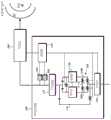
图1示出了根据本公开一实施例的示例性氧气浓缩器100。如图所示,呼吸机200被布置成经由患者通气接口12将由氧气浓缩器100产生的高氧气含量的气体输送至患者13。取决于各种因素,包括例如患者13的药方、患者的活动水平、用户可调整的设置以及患者在给定时刻的呼吸状态,呼吸机200可以指示氧气浓缩器100产生具有特定氧气浓度的特定流量(例如,体积流量)的气体。然后,呼吸机200可以经由患者通气接口12向患者13提供这样的高氧气含量的气体,考虑到患者通气接口12中对额外的环境空气的任何夹带,向患者13提供所需程度的患者呼吸功帮助和目标FiO2。FIG. 1 illustrates an
通常,为了从环境空气中产生高氧气含量的气体,氧气浓缩器100的压缩机110将环境空气泵送通过一个或多个吸附筛床120,该一个或多个吸附筛床120从加压空气中除去氮。所得的具有高氧气浓度(例如,>90%)的气体流入产物储箱130中以输送到呼吸机200。更详细地,氧气浓缩器100的控制器140可以控制阀单元150,以便周期性地使加压环境空气进入筛床120,并排出由筛床提取的氮废物。如图1所示,例如,可以提供两个具有相反操作周期的筛床120(例如筛床A和筛床B),筛床A向产物储箱130中填充高氧气含量的气体的同时,筛床B正在将氮排放到环境中,反之亦然。Typically, to produce a high oxygen content gas from ambient air, the
本公开设想了修改和/或补充这样的过程的各种方式,以便微调氧气浓缩器100以在特定的氧气浓度产生期望的气体流量。这种氧气浓缩器100可以与呼吸机200一起使用,以实时满足患者13变化的需求。The present disclosure contemplates various ways to modify and/or supplement such a process in order to fine-tune the
更详细地参考阀单元150的阀和导管的布置,可以看出,图1的示例性氧气浓缩器100提供了第一筛床流动路径160a和第二筛床流动路径160b,第一筛床流动路径160a从压缩机110通过阀单元150的阀V1到筛床A的入口,第二筛床流动路径160b从压缩机110通过阀单元150的阀V3到筛床B的入口。除了这些筛床流动路径160a,160b之外,氧气浓缩器100还包括旁路流动路径170,旁路流动路径170绕过一个或多个筛床120,从压缩机110通过阀单元150的阀V6到产物储箱130。通过控制阀V6,控制器140可以允许来自压缩机110的加压环境空气直接流到产物储箱130,而无需先通过筛床120。避免与筛床120相关的压降的这种环境空气然后可以在产物储箱130中与从筛床120输出的高氧气含量的气体混合。与仅从筛床120来填充产物储箱130相比,由于流过旁路流动路径170的环境空气的附加体积,环境空气和筛床输出的混合物可以在产物储箱130中更快地累积,同时具有较低的氧气浓度。通过适当地控制阀单元150,控制器140可以选择性地控制流入产物储箱130的流速和所得产物气体的氧气浓度,以便满足呼吸机200的需求。Referring to the arrangement of valves and conduits of
例如,为了达到93%的氧气浓度,不具有旁路流动路径170的常规氧气浓缩器的压缩机可能需要产生在氧气浓缩器的输出处所需流量的大约10倍。也就是说,2L/min的氧气浓缩器可能需要产生20L/min的压缩气体才能产生2L/min的氧气。通过使用旁路流动路径170,本公开的氧气浓缩器100可以允许在所输送的氧气浓度与氧气浓缩器100可输送的连续流量(例如,分钟通气量)之间进行折衷。例如,代替输送2L/min的流量,氧气浓缩器100可以设置成以1.8L/min的氧气(经由筛床120)和2L/min的环境空气(经由旁路阀170)输送3.8L/min的流量。所输送的气体的氧气浓度将下降到大约60%,但总流量将增加到3.8L/min。下游呼吸机200以大约3:1的比例用夹带的空气来放大该流量,因此通过使用呼吸机200,氧气浓缩器100可以输送11.4L/min(3*3.8)的分钟通气量,%FiO2约为32%。相比之下,当输送2L/min的93%氧气时,由呼吸机200放大的氧气浓缩器100将仅向患者13输送6L/min(3*2),但以50%的FiO2。这样,氧气浓缩器100可以产生高达20L/min的空气(完全绕过筛床120),然后可以由呼吸机200以大约21%(环境空气中的氧气浓度)的FiO2放大到60L/min(20*3)。这可以使小型氧气浓缩器100满足非常活跃的患者13的分钟水平要求。随着患者活动水平的提高,最好提供更多的通气和更少的氧气,而不是提供更多的氧气。通过使用旁路流动路径170,氧气浓缩器100可以在例如2L/min至20L/min之间改变总气体输出,其中氧气浓度相应地从大约93%到大约21%变化。氧气浓缩器100因此可以同时充当压缩机和氧气浓缩器,其滴定水平可通过呼吸机200控制,如下所述。For example, to achieve an oxygen concentration of 93%, the compressor of a conventional oxygen concentrator without a
控制器140可以通过生成用于控制阀单元150的各个阀(例如,V1-V6)的控制信号来控制阀单元150。例如,可以响应于呼吸机200发出的命令来生成控制信号。在这种情况下,可以根据主/从布置来控制阀单元150,其中呼吸机200用作主机,而控制器140或氧气浓缩器100用作从机。呼吸机200(例如,基于诸如患者13的药方、患者的活动水平、用户可调节的设置以及由呼吸机200测量的患者的呼吸状态之类的输入)可以得出流量和/或氧气浓度的设定值,并且控制器140可以适当地生成控制信号以达到该设定值。在产生控制信号时,控制器140还可以考虑流体地联接到产物储箱130的出口的压力传感器180和/或氧气浓度传感器190的测量值。这些测量值可以反馈给控制器140,并且可以与来自呼吸机200的设定值一起用作附加输入。控制器140可以例如用作比例积分微分(PID)控制器或执行其他已知的控制回路反馈机构。The
图2示出了在旁路流动路径170包括开/关阀V6的情况下用于控制阀单元150的示例性控制信号。在图2的示例中,阀单元150被控制为执行三阶段循环,其中来自压缩机110的压缩空气在第一阶段中通过筛床A,在第二阶段中通过筛床B,在第三阶段中,经由开/关阀V6和旁路流动路径170直接进入产物储箱130。2 shows an exemplary control signal for controlling the
图3示出了在旁路流动路径170包括比例阀V6的情况下用于控制阀单元150的示例性控制信号。在图3的示例中,控制阀单元150以执行两阶段循环,其中来自压缩机110的压缩空气在第一阶段中通过筛床A,在第二阶段中通过筛床B,比例阀V6始终处于受控状态以选择性地允许一部分压缩空气经由旁路流动路径170直接进入产物储箱130。FIG3 shows an exemplary control signal for controlling the
在关于图1至图3所述的示例中,旁路流动路径170将产物储箱130直接连接到压缩机110,即,流体地联接到筛床120的同一压缩机110。所公开的主题并不旨在限于此。例如,旁路流动路径170可以替代地从与压缩机110不同的单独的专用旁路压缩机延伸。可以根据控制器140生成的控制信号来打开和关闭这种专用旁路压缩机或者调节专用压缩机的输出(例如,每分钟转数(rpm)),以便选择性地允许从专用旁路压缩机到产物储箱150的流动,以实现与阀单元150的阀V6相同的效果。在以这样的方式控制专用旁路压缩机的情况下,可以省略阀V6。专用旁路压缩机可以被包括在氧气浓缩器100的壳体中,或者可以是单独的附加组件,该附加组件的输出经由专用连接器连接到氧气浓缩器100的旁路流动路径170。In the examples described with respect to FIGS. 1-3 ,
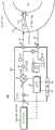
图4示出了与专用旁路压缩机一起使用的氧气浓缩器400的示例,该专用旁路压缩机是如上所述的单独的附加组件。氧气浓缩器400可以与关于图1所描述的氧气浓缩器100相同,并且可以包括压缩机410、筛床420、产物储箱430、控制器440、阀单元450、筛床流动路径460a,460b、旁路流动路径470、压力传感器480以及氧浓度传感器490,它们与氧气浓缩器100的压缩机110、筛床120、产物储箱130、控制器140、阀单元150、筛床流动路径160a,160b、旁路流动路径170、压力传感器180以及氧气浓度传感器190相同,但具有以下差异。图1的旁路流动路径170从压缩机110延伸到产物储箱130,但是图4的旁路流动路径470没有从压缩机410延伸到产物储箱430,而是从外部压缩机流体端口472延伸到产物储箱430。此外,在阀单元450中省略了阀单元150的阀V6,并且由控制器440生成的控制信号被用于经由外部压缩机信号端口474来控制外部旁路压缩机。如上所述,可以根据控制信号来打开和关闭这种外部旁路压缩机或者调节外部压缩机的输出,以便实现与阀V6相同的效果。FIG4 shows an example of an
图5示出了包括氧气浓缩器模块510和压缩机模块520的示例性模块化系统500。氧气浓缩器模块510可以容纳图4的氧气浓缩器400(例如以20-30PSI提供每分钟0-2升O2或每分钟0-20升空气,并具有1-2小时范围的100Wh电池),压缩机模块520容纳外部压缩机(例如,以20-30PSI提供每分钟0-10升空气,并具有2-3小时范围的100Wh电池)。如模块化系统500的顶部和底部的大箭头所示,氧气浓缩器模块510和压缩机模块520可以可拆卸地附接以形成单个单元。例如,用户可以沿箭头方向将两个模块510,520一起滑动,以使它们作为一个单元锁定在一起,而氧气浓缩器模块510的外部压缩机流体端口472流体地联接到压缩机模块520的压缩气体输出,氧气浓缩器模块510的外部压缩机信号端口474电联接到压缩机模块520的信号输入端口。使两个模块510,520沿相反方向滑动可以解锁并分离模块510,520,允许它们分开使用。这样,氧气浓缩器模块510可以由仅需要氧气治疗的患者使用,压缩机模块520可以由仅需要机械通气的患者使用,并且两个单元的组合可以由需要氧气和机械通气的人们使用。还可以设想,氧气浓缩器模块510的顶部或压缩机模块520的顶部(或由氧气浓缩器模块510的顶部和压缩机模块520的顶部形成的组合表面)可以用作用于放置呼吸机200的托架。同样,氧气浓缩器模块510的底部或压缩机模块520的底部(或由氧气浓缩器模块510的底部和压缩机模块520的底部形成的组合表面)可以用作辅助电池组的附接件。FIG5 shows an exemplary
图6示出了包括氧气浓缩器模块610的另一示例性模块化系统600。氧气浓缩器模块610可以容纳图1的氧气浓缩器100或图4的氧气浓缩器模块400。如图所示,在将辅助的热插拔电池组620和/或持续气道正压通气(CPAP)模块630(例如,利用用于CPAP的22mm ISO锥形连接器)附接到氧气浓缩器模块610的选项中,模块化系统600具有另外的模块性。氧气浓缩器610的顶部可以用作用于附接CPAP模块630的托架,并且可以包括闩锁释放器和电接触件。同样,氧气浓缩器610的底部可以用作用于附接电池组620的托架,并且可以包括闩锁释放器和电接触件。氧气浓缩器模块610还可以包括直径指数安全系统(DISS)或快速连接(Quick Connect)以及用户界面,该用户界面包括例如开/关按钮、电池电量指示器和用于呼吸机200的无线呼吸机连接。这种模块性可以代替或附加到与如关于图5的模块化系统500所描述的外部压缩机模块520的附接件。FIG. 6 shows another exemplary
在氧气浓缩器100,400,510,610的上述示例中,通过绕过氧气浓缩器100,400,510,610的筛床120,420的旁路流动路径170、470实现了对进入产物储箱130,430的流速和所得产物气体的氧气浓度的选择性控制。然而,本公开不旨在限于此。例如,控制器140,440可以有意地“搞混”以其他方式常规构造的氧气浓缩器的阀的定时。通常,滴定氧气浓缩器的阀门的定时以在筛床中产生最有效的氧气提取。通过控制压缩机110,410和/或阀单元150,450以修改筛床循环的定时,控制器140,440可以有意地防止氧气和氮在筛床120,420中有足够的时间完全分离。作为结果,产物储箱130,430可以充满具有降低的氧气浓度的产物气体,并且可以潜在地允许产物气体以更高的流速流向下游呼吸机200。控制器140,440可以例如参考次佳的压缩机输出和阀控制定时的查找表,次佳的压缩机输出和阀控制定时不能在筛床120,420中实现最有效的氧气和氮分离。使用这种查找表,控制器140,440可以响应于呼吸机200发出的命令生成控制信号,以实时满足患者13变化的需求。在这种情况下,可以省略旁路流动路径170,470和阀V6。In the above-described examples of
图7示出了根据本公开一实施例的示例性通气系统700。如图所示,通气系统700可以包括如图1和图4所示的呼吸机200和与患者13流动连通放置的通气患者接口12,以及如分别关于图1、图4、图5和图6所描述的氧气浓缩器100,400,510,610中的任何一个。呼吸机200可以布置成将由氧气浓缩器100,400,510,610产生的高氧气含量的气体经由患者通气接口12输送至患者13。患者通气接口12可以包括诸如全脸面罩或鼻罩之类的装置,该装置可以被放置成与患者13的上呼吸道(即鼻腔和/或口腔)直接气流连通。除了用于将高氧气含量的气体输送给患者13的一个或多个喷嘴15之外,患者通气接口12还可以具有用于夹带额外的环境空气以输送给患者13的一个或多个孔。可用于本公开主题的具有喷嘴15和夹带孔的患者通气接口12的示例可以在例如标题为“具有集成式射流泵的患者接口”的美国专利申请公开No.2019/0099570中找到,该专利申请的全部公开内容通过引用并入本文,并且该患者通气接口12的示例可以包括例如Breathe Technologies,Inc.的

取决于各种因素,包括例如患者13的药方、患者的活动水平、用户可调节的设置以及给定时刻患者的呼吸状态,夹带流量QE(并且因此总流量QT)可能会变化,从而导致患者吸入氧气分数%FiO2随着与一个或多个喷嘴15排出的高氧气含量的气体成比例地输送或较多或较少的环境空气而变化。通过测量由一个或多个喷嘴15排出的气体的流量QN以及患者通气接口12中的压力,呼吸机200可以计算或估算总流量QT。呼吸机200可以指示氧气浓缩器100,400,510,610根据所估算或计算的总流量QT来产生特定流量的具有特定氧气浓度的气体。然后,呼吸机200可以经由患者通气接口12向患者13提供这种高氧气含量的气体,从而考虑到患者通气接口12中夹带了额外的环境空气,向患者13提供所需程度的患者呼吸功帮助和目标%FiO2。Depending on various factors, including, for example, the medication of the
呼吸机200可以包括第一入口端口16,氧气浓缩器100,400,510,610通过第一入口端口16将高氧气含量的气体提供给呼吸机200。第一入口端口16可以与入口过滤器24连通,该入口过滤器24将颗粒和其他污染物从最终被输送到患者的呼吸气体中去除。源自氧气浓缩器100,400,510,610的高氧气含量的气体的压力可以通过阀26来调节,该阀26具有与入口过滤器24气流连通的阀入口端口26a和与呼吸机200的出口端口28气流连通的阀出口端口26b。可以选择性地调节阀26的状态,以将所需体积/压力的气体从氧气浓缩器100,400,510,610输送到患者13。阀26的致动可以由控制器30控制,该控制器30执行本公开所设想的各种方法,如将在下面进一步详细描述的。The
通过阀26输送的呼吸气体流可以通过出口端口28进入到与上述患者通气接口12联接的气体输送管道32。气体输送管道32可以是例如具有预定内径(诸如22mm或更小)的塑料管。取决于患者13的呼吸状态,在患者通气接口12和阀26的输出处(即阀出口端口26b)之间可能产生压力差。The flow of breathing gas delivered through
为了确定这样的压力差,通气系统700可以包括双压力传感器,双压力传感器包括阀压力传感器34和患者接口压力传感器36。阀压力传感器34可以设置在呼吸机200内并且可以监测阀出口端口26b处的压力。患者接口压力传感器36也可以物理地布置在呼吸机200内,但是在连接到呼吸机200的传感器入口端口40的压力传感器管线38上与患者通气接口12直接气流连通。在呼吸机200运行时,可以连接压力传感器管线38以及气体管道32内的气压以输送吹扫流从而净化压力传感器管线38。这可以通过连接到两者的净化螺线管42来完成。根据患者的呼吸阶段或阀压力与患者接口压力之间的压力差,吹扫可以是连续的或间歇的。To determine such a pressure differential, the
除了测量患者通气接口12和阀输出26b处的压力差之外,还可以利用实际从阀26输出的呼吸气体的流量测量值。为此,呼吸机200可以包括与阀26和出口端口28成一直线的流量传感器43。In addition to measuring the pressure difference between the
呼吸机200可以测量患者通气接口12中的压力以及由患者通气接口12的一个或多个喷嘴15排出的气体的流量。例如,控制器30可以与阀压力传感器34和患者接口压力传感器36中一个或两个通信以测量压力,并且可以与流量传感器43通信以测量流量。基于测量的压力和流量,控制器30然后可以估算或计算总流量QT和/或各种其他参数,如下面更详细描述的。为此,呼吸机200还可以包括喷嘴数据存储器31,该喷嘴数据存储器31可以存储与多个喷嘴几何形状中的每一个相关联的一个或多个常数。在使用期间,控制器30可以基于所测量的流量、所测量的压力以及所存储的与一个或多个喷嘴15的喷嘴几何形状相关联的一个或多个常数来计算总流量QT。基于所计算的总流量QT,控制器30还可以计算患者的%FiO2。控制器30可以随着用户的活动水平和呼吸变化以及随着(例如,使用诸如触摸屏或按钮之类的输入69和诸如显示器之类的输出62)对呼吸机200的用户可调节设置进行修改来实时地连续地计算总流量QT和/或患者13的%FiO2。The
基于所计算的总流量QT和/或患者的%FiO2,控制器30可以例如通过使信号(例如,射频无线信号)从呼吸机200传输至氧气浓缩器100,400,510,610来指示氧气浓缩器100,400,510,610。在从呼吸机200接收到信号后,氧气浓缩器100,400,510,610可以调节其产生的高含氧量的气体的压力、流量和/或氧气浓度,以实时满足患者变化的需求。可以在如以上关于图1和图4所描述的氧气浓缩器100,400,510,610内进行这种调节。这样,呼吸机200可以根据主/从布置来控制氧气浓缩器100,400,510,610,其中呼吸机200用作主机,而氧气浓缩器100,400,510,610用作从机。Based on the calculated total flowQT and/or the patient's %FiO2 , the
图8示出了根据所公开的主题的一实施例的可由呼吸机200全部或部分地执行的示例性操作流程。图8的操作流程可以用于根据由一个或多个喷嘴15排出的气体的测量流量QN(喷嘴流量)和患者通气接口12中的测量压力Paw(气道压力)来计算总流量QT。等效地,在已知由一个或多个喷嘴15排出的气体的流量QN的情况下,图8的操作流程可以用于计算由通过喷嘴15的流量QN产生的夹带流量QE=QT-QN以及由此衍生的各种其他值。FIG8 illustrates an exemplary operational flow that may be performed in whole or in part by a
通常,夹带受到喷嘴下游压力的影响,在患者通气接口12(例如

其中,停滞压力PS是排出气体的流量QN的函数,可以计算为二次方程式Among them, the stagnation pressurePS is a function of the exhaust gas flow rateQN and can be calculated as a quadratic equation

a、b和c是取决于特定喷嘴几何形状的常数。可以通过找到给定流量将产生的停滞压力来针对每种喷嘴几何形状预先确定常数a、b和c。在
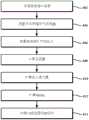
图8的操作流程可以从步骤802开始,在步骤802中,存储与多个喷嘴几何形状中的每个几何形状相关联的一个或多个常数。例如,可以针对(例如,用于
在使用通气系统700对患者13进行治疗期间,图8的操作流程可以继续进行步骤804和步骤806,在步骤804中,测量由患者通气接口12的一个或多个喷嘴15排出的气体的流量QN,在步骤806中,测量患者通气接口12中的压力Paw。测量压力Paw可以包括控制器30与阀压力传感器34和患者接口压力传感器36之间的通信。例如,测量压力Paw可以被定义为由患者接口压力传感器36测量的患者通气接口12中的压力与由阀压力传感器34测量的阀出口端口26b处的压力之间的差。在获取了测量流量QN和测量压力Paw的情况下,操作流程可以继续进行步骤808,在步骤808中,计算由呼吸机200输送到患者13的气体和夹带空气的总流量QT。例如,控制器30可以使用上述方程式,基于测量流量QN和测量压力Paw以及存储的常数a、b和c来计算总流量QT,例如,通过使用常数a和b以及测量流量QN来计算停滞压力PS,然后使用测量流量QN、测量压力Paw、停滞压力PS和常数c来计算总流量QT。在计算总流量QT时,控制器30可以从喷嘴数据存储器31读取常数a、b和c,或者在常数被存储在患者通气接口12的存储器中的情况下,控制器30可以在患者通气接口12连接到呼吸机200时(例如,经由将常数下载到呼吸机200的智能连接器),从外部存储器读取常数a、b和c。During treatment of the patient 13 using the
在步骤810中,可以计算可从总流量QT衍生的各种值中的任何一个,例如一个或多个吸入潮气量。例如,总吸入潮气量TotVt可以计算为总流量QT相对于时间的积分,由一个或多个喷嘴15排出的气体的吸入潮气量NozVt可以计算为测量流量QN相对于时间的积分,和/或夹带空气的吸入潮气量EntVt可以计算为夹带流量QE=QT-QN相对于时间的积分。在步骤812中,控制器30可基于由一个或多个喷嘴15排出的气体的吸入潮气量和夹带空气的吸入潮气量来计算%FiO2。例如,假设由一个或多个喷嘴15排出的气体是100%氧气,则%FiO2可计算为%FiO2=100(NozVt+0.21EntVt)/TotVt,其中21%是环境空气中氧气的大约百分比。更一般地说,对于由一个或多个喷嘴15排出的任意气体(例如,如上所述,在氧气浓缩器100,400,510,610被控制为输送较低的氧气浓度的情况下),%FiO2可以计算为:%FiO2=100(NozVt+0.21EntVt)/TotVt,其中100X是由一个或多个喷嘴15排出的气体中所含氧气的百分比。可以根据氧气浓缩器100,400,510,610供应的气体的已知氧气浓度(例如,基于控制器30发出的当前/先前设定值和/或氧气浓度传感器190的测量值)来确定值X,值X定义了由一个或多个喷嘴15排出的气体的氧气浓度。In
最后,在步骤814中,呼吸机200的控制器30可以基于计算出的总流量QT或%FiO2,例如如上所述通过使信号从呼吸机200传输到氧气浓缩器100,400,510,610来指示氧气浓缩器100,400,510,610。在从呼吸机200接收到信号后,氧气浓缩器100,400,510,610可以调节其产生的高氧气含量的气体的压力、流量和/或氧气浓度,以产生期望的总流量QT和/或%FiO2。Finally, in
在以上示例中,针对每种喷嘴几何形状存储常数a、b和c。但是,也可以设想针对每个喷嘴几何形状可以仅存储常数c,针对可能的流量QN的范围进一步存储停滞压力PS。在将呼吸机200设计为仅用于单个喷嘴几何形状的情况下,可能根本不需要存储任何常数,并且可以省略步骤802。总流量QT可以简单地作为测量流量QN和测量压力Paw的函数计算得出,而无需针对不同的喷嘴几何形状修改上述方程式。In the above example, constants a, b, and c are stored for each nozzle geometry. However, it is also conceivable that only constant c may be stored for each nozzle geometry, and stagnation pressure PS may be further stored for a range of possible flows QN. In the case where the
图9示出了在不同流量下计算和测量的喷嘴的停滞压力的示例。如上所述,使用常数a=0.191和b=0.3828以及针对停滞压力PS的上述方程式来产生图9所示的计算关系。图9所示的另一关系(“测量的cmH20”)是测量UCC患者接口的停滞压力PS的实验结果。从图9中可以看出,测量关系与计算关系非常匹配,这表明停滞压力PS和喷嘴流量QN之间存在二次关系。FIG9 shows an example of calculated and measured stagnation pressures for a nozzle at different flow rates. As described above, constants a=0.191 and b=0.3828 were used and the above equation for stagnation pressure PS was used to generate the calculated relationship shown in FIG9 . Another relationship shown in FIG9 (“measured cmH20”) is the experimental result of measuring the stagnation pressure PS of the UCC patient interface. As can be seen in FIG9 , the measured relationship matches the calculated relationship very well, indicating that there is a quadratic relationship between the stagnation pressure PS and the nozzle flow rate QN.
图10示出了在不同流量下的喷嘴的计算和测量的Paw-QT曲线的示例。如上所述,图10所示的计算关系是使用常数c=8和针对上述总流量QT的方程式生成的,其中总流量QT是针对不同喷嘴流量QN的气道压力Paw的函数。其他关系(“Act-5”、“Act-10”等)是针对5、10、20和40L/min喷嘴流量QN测量总流量QT与气道压力Paw之间关系的实际实验结果。如图10所示,测量关系与计算关系非常匹配,这表明气道压力Paw与总流量QT之间存在线性关系。FIG10 shows examples of calculated and measured Paw -QT curves for a nozzle at different flow rates. As described above, the calculated relationship shown in FIG10 is generated using the constant c=8 and the equation for the total flow rate QT described above, where the total flow rate QT is a function of the airway pressure Paw for different nozzle flow rates QN. The other relationships ("Act-5", "Act-10", etc.) are actual experimental results of measuring the relationship between the total flow rate QT and the airway pressure Paw for nozzle flow rates QN of 5, 10, 20, and 40 L/min. As shown in FIG10, the measured relationship matches the calculated relationship very well, indicating that there is a linear relationship between the airway pressure Paw and the total flow rate QT.
图11示出了根据所公开的主题的一实施例的可由呼吸机200全部或部分地执行的另一示例性操作流程。在图11的示例中,不是如上所述使用常数a、b和c以及总流量QT和停滞压力PS之间的关系来计算总流量QT,而是可以将针对给定的一喷嘴(或多个喷嘴)的预定特性Paw-QT曲线预先存储,并将其用于估算针对测量压力Paw和喷嘴流量QN的总流量QT。操作流程可以开始于步骤1102,在步骤1102中,将总流量数据存储在例如呼吸机200的喷嘴数据存储器31中。举例来说,总流量数据可以包括针对一个或多个喷嘴的图10的特性曲线(例如其基础数据,该基础数据可以以表格形式或作为参数化方程式存储)。如在存储常数a、b,c的情况下,预存储的特性曲线可以可替代地存储在每个患者接口12中的存储器中,表征该特定患者接口12。对于给定的一患者接口12,喷嘴数据存储器31或外部存储器可以针对由患者通气接口12的一个或多个喷嘴15排出的气体的流量QN的多个测量值中的每一个测量值(例如,如图10所示QN=5、10、20、30、40)来存储与患者通气接口12中的压力Paw的多个测量值相对应的总流量QT的多个测量值。FIG11 illustrates another exemplary operational flow that may be performed in whole or in part by the
在使用通气系统700对患者13进行治疗期间,图11的操作流程可以继续进行步骤1104和步骤1106,在步骤1104中,测量由患者通气接口12的一个或多个喷嘴15排出的气体的流量QN,在步骤1106中,如上所述,测量患者通气接口12中的压力Paw。在获取了测量流量QN和测量压力Paw的情况下,操作流程可以继续进行步骤1108,在步骤1108中,基于测量压力Paw与针对测量流量QN存储的总流量QT的多个测量值的比较来估算总流量QT。例如,控制器30可以参考喷嘴数据存储器31以查询图10中所示的特性Paw-QT曲线,找到与测量流量QN相对应的特性Paw-QT曲线,并沿该曲线读取与测量压力Paw相对应的总流量QT的值。During treatment of the patient 13 using the
在如上所述估算了总流量QT的情况下,图11的操作流程可以继续进行步骤1110、步骤1112和步骤1114,在步骤1110中,计算一个或多个吸入潮气量或从总流量QT得出的各种其他值中的任何一个,在步骤1112中,计算患者13的%FiO2,在步骤1114中,向氧气浓缩器100传输信号,所有这些步骤可以以与图8的操作流程的步骤810、812和814相同的方式执行。唯一的区别是,在图10的情况下,总流量QT是使用预先存储的特性曲线估算的,而不是使用测量压力Paw、测量流量QN和一个或多个表征患者接口12的常数来计算的。在从呼吸机200接收到信号后,氧气浓缩器100,400,510,610就可以调节其产生的高氧气含量的气体的压力、流量和/或氧气浓度,以产生期望的总流量QT和/或%FiO2。In the case where the total flow QT is estimated as described above, the operation flow of FIG. 11 may proceed to step 1110,
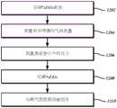
图12示出了根据所公开的主题的一实施例的可由呼吸机200全部或部分地执行的另一示例性操作流程。在图12的示例中,不是估算总流量QT作为计算患者的%FiO2的前提,而是可以将每个喷嘴的%FiO2数据预先存储,并且将其用于估算针对测量压力Paw和喷嘴流量QN的%FiO2。操作流程可以开始于步骤1202,在步骤1202中,将%FiO2数据存储在例如呼吸机200的喷嘴数据存储器31中。%FiO2数据可以包括针对一个或多个喷嘴的特性曲线(例如其基础数据,该基础数据可以以表格形式或作为参数化方程式存储)。如在存储常数a、b、c的情况下,预存储的特性曲线可以可替代地存储在每个患者接口12中的存储器中,表征该特定患者接口12。对于给定的一患者接口12,喷嘴数据存储器31或外部存储器可以针对由患者通气接口12的一个或多个喷嘴15排出的气体的流量QN的多个测量值(例如,如图10所示,QN=5、10、20、30、40)中的每一个测量值来存储与患者通气接口12中的压力Paw的多个测量值相对应多个%FiO2的测量值。这种特性Paw-%FiO2曲线可以通过在实验室中在各种压力Paw和喷嘴流量QN下测量%FiO2通过实验获得,或者可以从上文关于图11的操作流程所描述的总流量数据导出。FIG12 illustrates another exemplary operational flow that may be performed in whole or in part by the
在使用通气系统700治疗患者13的过程中,图11的操作流程可以继续进行步骤1204和步骤1206,在步骤1204中,测量由患者通气接口12的一个或多个喷嘴15排出的气体的流量QN,在步骤1206中,如上所述测量患者通气接口12中的压力Paw。在获取了测量流量QN和测量压力Paw的情况下,操作流程可以继续进行步骤1208,在步骤1208中,基于测量压力Paw与针对测量流量QN存储的FiO2的多个测量值的比较来估算患者的FiO2。例如,控制器30可以参考喷嘴数据存储器31以查询针对特定的一个或多个喷嘴15的%FiO2数据,找到与测量流量QN相对应的特性Paw-%FiO2曲线,并沿该曲线读取与测量压力Paw相对应的%FiO2的值。在如上所述估算了患者的%FiO2的情况下,图12的操作流程可以继续进行步骤1210,在步骤1210中,向氧气浓缩器100传输信号,该步骤可以以与图8的步骤814或图11的步骤1114相同的方式执行。唯一的区别是,在图12的情况下,%FiO2是直接使用预先存储的特性曲线来估算的,而不是根据总流量QT计算得出的。在从呼吸机200接收到信号后,氧气浓缩器100,400,510,610可以调节其产生的高氧气含量的气体的压力、流量和/或氧气浓度,以产生期望的夹带率和/或%FiO2。During treatment of
在图8、图11和图12的上述示例性操作流程中,计算或估算了总流量QT和/或患者的%FiO2,其用于表征给定时刻患者13的需求,以控制氧气浓缩器100。然而,所公开的主题并不旨在限于这些特定参数。例如,可以替代地使用各种导出的或其他相关参数,例如夹带流量QE、夹带率η=(QT-QN)/QN或潮气量TotVt、NozVt或EntVt。使用所公开的主题,可以基于所测量的患者气道压力Paw和喷嘴流量QN来计算和/或估算任何和所有这样的值。In the above-described exemplary operational flows of FIGS. 8 , 11 , and 12 , total flow QT and/or patient % FiO2 are calculated or estimated, which are used to characterize the needs of
氧气浓缩器100,400的控制器140,440和/或呼吸机200的控制器30及其各自的功能可以用诸如微控制器或控制处理器之类的可编程集成电路设备来实现。广泛地,设备可以接收某些输入,并且基于这些输入,可以生成某些输出。针对输入执行的特定操作可以被编程为由控制处理器执行的指令。为此,设备可以包括算术/逻辑单元(ALU)、各种寄存器和输入/输出端口。诸如EEPROM(电可擦除/可编程只读存储器)之类的外部存储器可以连接到设备,以永久存储和检索程序指令,并且还可以有内部随机存取存储器(RAM)。例如在向现有设备提供更新的情况下,用于实现控制器140,440和/或控制器30的任何所公开功能的计算机程序可以驻留在这种非暂时性程序存储介质上以及诸如半导体存储器(例如,IC卡)之类的可移动非暂时性程序存储介质上。存储在程序存储介质或计算机可读介质上的程序指令的示例除了包括可由处理器执行的代码外,还可以包括用于由诸如现场可编程门阵列(FPGA)或可编程逻辑器件(PLD)之类的可编程电路执行的状态信息。The
以上描述是通过示例而非限制的方式给出的。鉴于以上公开,本领域技术人员可以设计出在本文公开的本发明的范围和精神内的变型。此外,本文公开的实施例的各种特征可以单独使用,或彼此以不同的组合使用,并且不旨在限于本文所述的特定组合。因此,权利要求的范围不受所示实施例的限制。The above description is given by way of example and not limitation. In view of the above disclosure, those skilled in the art may design variations within the scope and spirit of the invention disclosed herein. In addition, the various features of the embodiments disclosed herein may be used alone or in different combinations with each other, and are not intended to be limited to the specific combinations described herein. Therefore, the scope of the claims is not limited by the illustrated embodiments.
Claims (15)
Priority Applications (1)
| Application Number | Priority Date | Filing Date | Title |
|---|---|---|---|
| CN202310532696.1ACN116808374A (en) | 2019-05-22 | 2020-05-22 | Oxygen concentrator with sieve bed bypass and control method thereof |
Applications Claiming Priority (4)
| Application Number | Priority Date | Filing Date | Title |
|---|---|---|---|
| US201962851204P | 2019-05-22 | 2019-05-22 | |
| US62/851,204 | 2019-05-22 | ||
| US16/874,472US11607519B2 (en) | 2019-05-22 | 2020-05-14 | O2 concentrator with sieve bed bypass and control method thereof |
| US16/874,472 | 2020-05-14 |
Related Child Applications (1)
| Application Number | Title | Priority Date | Filing Date |
|---|---|---|---|
| CN202310532696.1ADivisionCN116808374A (en) | 2019-05-22 | 2020-05-22 | Oxygen concentrator with sieve bed bypass and control method thereof |
Publications (2)
| Publication Number | Publication Date |
|---|---|
| CN111973849A CN111973849A (en) | 2020-11-24 |
| CN111973849Btrue CN111973849B (en) | 2023-06-09 |
Family
ID=70802689
Family Applications (2)
| Application Number | Title | Priority Date | Filing Date |
|---|---|---|---|
| CN202310532696.1APendingCN116808374A (en) | 2019-05-22 | 2020-05-22 | Oxygen concentrator with sieve bed bypass and control method thereof |
| CN202010443845.3AActiveCN111973849B (en) | 2019-05-22 | 2020-05-22 | Oxygen concentrator with sieve bed bypass and control method thereof |
Family Applications Before (1)
| Application Number | Title | Priority Date | Filing Date |
|---|---|---|---|
| CN202310532696.1APendingCN116808374A (en) | 2019-05-22 | 2020-05-22 | Oxygen concentrator with sieve bed bypass and control method thereof |
Country Status (4)
| Country | Link |
|---|---|
| US (3) | US11607519B2 (en) |
| EP (2) | EP4159301A3 (en) |
| JP (3) | JP7080921B2 (en) |
| CN (2) | CN116808374A (en) |
Families Citing this family (11)
| Publication number | Priority date | Publication date | Assignee | Title |
|---|---|---|---|---|
| US10894139B2 (en)* | 2018-01-19 | 2021-01-19 | Ergo-Flex Technologies, LLC | Oxygen treatment device for mammals |
| US11400250B2 (en) | 2018-12-05 | 2022-08-02 | Aires Medical LLC | Mechanical ventilator with non-invasive option |
| US11135392B2 (en)* | 2018-12-05 | 2021-10-05 | Aires Medical LLC | Mechanical ventilator |
| US11123505B2 (en) | 2018-12-05 | 2021-09-21 | Aires Medical LLC | Breathing apparatus with breath detection software |
| US11229763B2 (en) | 2018-12-05 | 2022-01-25 | Aires Medical LLC | Mechanical ventilator with oxygen concentrator |
| CN115297918A (en)* | 2020-02-27 | 2022-11-04 | 费雪派克医疗保健有限公司 | Improvements regarding the provision of gas flow |
| US20220096781A1 (en)* | 2020-09-29 | 2022-03-31 | Covidien Lp | Synchronous control systems and methods for improved oxygen concentration accuracy in blower-based ventilators |
| US12290636B2 (en)* | 2021-06-16 | 2025-05-06 | Northman Ip Holdco Limited | Respiratory devices |
| US20230414888A1 (en)* | 2022-06-27 | 2023-12-28 | Dynasthetics, Llc | System for controlling and measuring oxygen delivery through a cpap adaptor |
| US12415051B2 (en) | 2023-09-07 | 2025-09-16 | Roam Technologies Pty Ltd. | Oxygen concentrator |
| EP4613312A1 (en)* | 2024-03-05 | 2025-09-10 | Axnar Med Tech GmbH | Modular oxygen supply system with at least two oxygen supply devices |
Citations (4)
| Publication number | Priority date | Publication date | Assignee | Title |
|---|---|---|---|---|
| US4813977A (en)* | 1987-12-29 | 1989-03-21 | Air Products And Chemicals, Inc. | Adsorptive nitrogen generation utilizing multiple adsorption beds |
| US5626131A (en)* | 1995-06-07 | 1997-05-06 | Salter Labs | Method for intermittent gas-insufflation |
| WO2015058036A1 (en)* | 2013-10-18 | 2015-04-23 | Silverbow Development Llc | Oxygen concentrator for mechanical ventilation |
| CN106456927A (en)* | 2014-03-28 | 2017-02-22 | 开罗股份有限公司 | Controlling oxygen concentrator timing cycle based on flow rate of oxygen output |
Family Cites Families (75)
| Publication number | Priority date | Publication date | Assignee | Title |
|---|---|---|---|---|
| US4421530A (en)* | 1982-09-13 | 1983-12-20 | Air Products And Chemicals, Inc. | Process for removing oxygen from mixed gas streams using a swing adiabatic absorption-isothermal desorption cycle |
| US4870960A (en)* | 1985-10-07 | 1989-10-03 | Litton Systems, Inc. | Backup breathing gas supply for an oxygen concentrator system |
| CA1297298C (en)* | 1986-09-22 | 1992-03-17 | Akira Kato | Oxygen enriching apparatus with means for regulating oxygen concentration of oxygen enriched gas |
| JPS6379710A (en)* | 1986-09-22 | 1988-04-09 | Teijin Ltd | Oxygen enricher |
| JPH11228107A (en)* | 1998-02-18 | 1999-08-24 | Taizo Nagahiro | Method and device for concentrating gaseous oxygen |
| GB9920694D0 (en) | 1999-09-03 | 1999-11-03 | Wabco Automotive Uk | Vehicle air supply systems |
| US6824590B2 (en) | 2000-11-07 | 2004-11-30 | Air Products And Chemicals, Inc. | Use of lithium-containing fau in air separation processes including water and/or carbon dioxide removal |
| US6605136B1 (en) | 2002-07-10 | 2003-08-12 | Air Products And Chemicals, Inc. | Pressure swing adsorption process operation and optimization |
| US20050045041A1 (en)* | 2003-08-29 | 2005-03-03 | Hechinger Glenn R. | Removable cartridge for swing-type adsorption system |
| US20050072423A1 (en) | 2003-10-07 | 2005-04-07 | Deane Geoffrey Frank | Portable gas fractionalization system |
| US20050072426A1 (en) | 2003-10-07 | 2005-04-07 | Deane Geoffrey Frank | Portable gas fractionalization system |
| US7066985B2 (en) | 2003-10-07 | 2006-06-27 | Inogen, Inc. | Portable gas fractionalization system |
| US7135059B2 (en) | 2003-10-07 | 2006-11-14 | Inogen, Inc. | Portable gas fractionalization system |
| EP1677895A2 (en) | 2003-10-07 | 2006-07-12 | Inogen, Inc. | Portable gas fractionalization system |
| US7279029B2 (en) | 2004-05-21 | 2007-10-09 | Air Products And Chemicals, Inc. | Weight-optimized portable oxygen concentrator |
| EP1776152A2 (en) | 2004-06-04 | 2007-04-25 | Inogen, Inc. | Systems and methods for delivering therapeutic gas to patients |
| EP1761742A1 (en) | 2004-06-28 | 2007-03-14 | Inogen, Inc. | Conserver design for a therapeutic breathing gas system |
| US20080276939A1 (en)* | 2004-07-08 | 2008-11-13 | Breas Medical Ab | Delta Flow Pressure Regulation |
| WO2006053272A1 (en) | 2004-11-12 | 2006-05-18 | Inogen, Inc. | Portable intelligent controller for therapeutic gas systems |
| WO2006091723A2 (en) | 2005-02-23 | 2006-08-31 | Inogen Inc. | Method and apparatus for controlling a gas fractionalization apparatus |
| US7708802B1 (en) | 2005-05-23 | 2010-05-04 | Inogen, Inc. | Gas fractionalization apparatus with built-in administrative and self-diagnostic functions |
| GB2427688A (en) | 2005-06-28 | 2007-01-03 | Inogen S A | Microwell plate |
| US7686870B1 (en) | 2005-12-29 | 2010-03-30 | Inogen, Inc. | Expandable product rate portable gas fractionalization system |
| US20080072907A1 (en) | 2006-09-22 | 2008-03-27 | Inogen Corporation | Oxygen conserver design for general aviation |
| JP5117700B2 (en) | 2006-09-28 | 2013-01-16 | 株式会社日立産機システム | Gas generator |
| US7857894B2 (en) | 2006-10-10 | 2010-12-28 | Inogen, Inc. | Adsorbent bed pressure balancing for a gas concentrator |
| JP2011502547A (en) | 2006-11-01 | 2011-01-27 | フィッシャー、ジョセフ | Portable life support device |
| US7780768B2 (en) | 2006-11-28 | 2010-08-24 | Inogen, Inc. | Gas concentrator with improved water rejection capability |
| US20090126736A1 (en) | 2007-07-16 | 2009-05-21 | Brenton Taylor | In-home medical data collection and reporting system |
| US20090131763A1 (en) | 2007-07-16 | 2009-05-21 | Brenton Taylor | Method for improving in-home patient monitoring |
| KR20090057520A (en) | 2007-12-03 | 2009-06-08 | 차진석 | Oxygen generator |
| AU2009251939B2 (en)* | 2008-05-27 | 2015-08-06 | Fisher & Paykel Healthcare Limited | Control of humidifier chamber temperature for accurate humidity control |
| CN102196837B (en) | 2008-08-22 | 2015-09-09 | 呼吸科技公司 | Methods and devices for providing mechanical ventilation utilizing an open airway interface |
| US20100224191A1 (en) | 2009-03-06 | 2010-09-09 | Cardinal Health 207, Inc. | Automated Oxygen Delivery System |
| CN111420208B (en)* | 2009-04-02 | 2023-07-04 | 呼吸科技公司 | Methods, systems and devices for non-invasive open ventilation using a gas delivery nozzle within an outer tube |
| WO2011029074A1 (en)* | 2009-09-03 | 2011-03-10 | Breathe Technologies, Inc. | Methods, systems and devices for non-invasive ventilation including a non-sealing ventilation interface with an entrainment port and/or pressure feature |
| AU2011258203A1 (en) | 2010-05-26 | 2013-01-10 | The Charles Stark Draper Laboratory, Inc. | Microfabricated artificial lung assist device, and methods of use and manufacture thereof |
| EP2590702B1 (en)* | 2010-07-09 | 2014-05-14 | Koninklijke Philips N.V. | Leak estimation using leak model identification |
| US20120055477A1 (en)* | 2010-09-07 | 2012-03-08 | Wilkinson William R | Oxygen concentrator apparatus configured for high altitude use |
| GB2485836A (en) | 2010-11-27 | 2012-05-30 | Alstom Technology Ltd | Turbine bypass system |
| US8440004B2 (en) | 2010-12-30 | 2013-05-14 | Inogen, Inc. | Advanced portable oxygen concentrator |
| BR112013019445A2 (en) | 2011-01-31 | 2020-10-27 | Breathe Technologies, Inc. | methods systems and devices for ventilation using a nasal ventilation mask with a collector and a compliant inner tube and nasal seal pad assembly |
| US9592360B2 (en) | 2011-04-22 | 2017-03-14 | Inogen, Inc. | Gas concentrator with removable cartridge adsorbent beds |
| US10695520B2 (en) | 2011-04-22 | 2020-06-30 | Inogen, Inc. | Gas concentrator with removable cartridge adsorbent beds |
| JP5888908B2 (en)* | 2011-09-09 | 2016-03-22 | 岩谷産業株式会社 | Concentration method of ozone gas |
| US10265493B2 (en) | 2011-11-21 | 2019-04-23 | Snap Cpap, Llc | Respiratory assembly |
| US8702841B2 (en) | 2012-04-17 | 2014-04-22 | Inogen, Inc. | Adsorber replacement notification for a portable gas concentrator |
| WO2013168036A1 (en)* | 2012-05-11 | 2013-11-14 | Koninklijke Philips N.V. | Systems and methods to determine the fraction of inhaled oxygen during ventilation. |
| ES2716051T3 (en) | 2012-09-12 | 2019-06-07 | Silverbow Dev Llc | Nasal interface device and systems for use with a respiratory assist device |
| US20140261426A1 (en)* | 2013-03-15 | 2014-09-18 | Breathe Technologies, Inc. | Dual Pressure Sensor Patient Ventilator |
| BR112015027096A2 (en) | 2013-04-24 | 2017-07-25 | Science Medical Llc | breathing devices and related systems and methods "priority claim |
| WO2015058089A1 (en) | 2013-10-18 | 2015-04-23 | Silverbow Development Llc | Techniques for determining patient airway pressure |
| EP3544146B1 (en)* | 2013-10-31 | 2023-11-29 | ResMed Paris SAS | An apparatus for treating a respiratory disorder with a power source connection |
| US10004869B2 (en) | 2013-12-27 | 2018-06-26 | Inogen, Inc. | Gas concentrator with removable cartridge adsorbent beds |
| US10137275B2 (en) | 2014-01-16 | 2018-11-27 | BreatheTechnologies, Inc. | Oxygen concentrator for high pressure oxygen delivery with oxygen circulation loop and improved portability |
| WO2015132682A1 (en) | 2014-03-04 | 2015-09-11 | Koninklijke Philips N.V. | Blending gaz enriched pressure support system and method |
| EP3169408A4 (en) | 2014-07-18 | 2018-01-03 | Silverbow Development, LLC | Conforming nasal pillow |
| US9283346B2 (en) | 2014-07-26 | 2016-03-15 | Inogen, Inc. | Personal use oxygen concentrator with integrated fire safety |
| GB201507549D0 (en) | 2015-04-29 | 2015-06-17 | Smiths Medical Int Ltd | Ventilator apparatus and systems |
| EP3310418B1 (en) | 2015-06-22 | 2020-02-12 | Caire Inc. | Wearable oxygen generator and docking station enabling higher oxygen flow capacity |
| US11266801B2 (en)* | 2015-10-09 | 2022-03-08 | University Of Utah Research Foundation | Ventilation devices and systems and methods of using same |
| US11123512B2 (en)* | 2015-10-23 | 2021-09-21 | Inogen, Inc. | Connection of a spontaneous delivery device to a concentrator |
| ES2940361T3 (en) | 2016-02-29 | 2023-05-05 | Inovytec Medical Solutions Ltd | Portable Lightweight Ventilator System |
| US20170340851A1 (en) | 2016-05-24 | 2017-11-30 | Silverbow Development, Llc | Oxygen gas concentrator with outlet accumulator |
| US10080521B2 (en) | 2016-08-01 | 2018-09-25 | Timothy Joshua Parrish | Sleep apnea bi-level positive airway pressure machine with advanced diagnostics and self-cleaning capabilities |
| EP3568184B1 (en) | 2017-01-13 | 2021-02-17 | Silverbow Development, LLC | Remote oxygen flow adjustment |
| WO2018140971A1 (en)* | 2017-01-30 | 2018-08-02 | Potter Electric Signal Company, Llc | Automatic nitrogen fill for a fire sprinkler system |
| EP3400984A1 (en)* | 2017-05-08 | 2018-11-14 | Philippe Goutorbe | Systems and methods for automatically adjusting a determined supply of fio2 generated from a cpap, niv or other ventilator system |
| US10792449B2 (en) | 2017-10-03 | 2020-10-06 | Breathe Technologies, Inc. | Patient interface with integrated jet pump |
| SG11202002927YA (en) | 2017-10-06 | 2020-04-29 | Fisher & Paykel Healthcare Ltd | Closed loop oxygen control |
| WO2019221852A1 (en) | 2018-05-13 | 2019-11-21 | Ahmad Samir Saleh | Portable medical ventilator system using portable oxygen concentrators |
| US20210346634A1 (en) | 2018-08-23 | 2021-11-11 | ResMed Pty Ltd | Methods and apparatus for controlling respiratory therapy with supplementary oxygen |
| EP4623979A2 (en)* | 2018-10-26 | 2025-10-01 | BMC Medical Co., Ltd. | Humidification assembly |
| JP7278383B2 (en) | 2018-12-31 | 2023-05-19 | コーニンクレッカ フィリップス エヌ ヴェ | Method and system for delivering oxygen to a patient |
| WO2020154700A1 (en) | 2019-01-24 | 2020-07-30 | Inogen, Inc. | Nasal interface apparatus and systems for use with a respiratory assist device |
- 2020
- 2020-05-14USUS16/874,472patent/US11607519B2/enactiveActive
- 2020-05-18JPJP2020086518Apatent/JP7080921B2/enactiveActive
- 2020-05-20EPEP22204541.1Apatent/EP4159301A3/enactivePending
- 2020-05-20EPEP20175818.2Apatent/EP3741445B1/enactiveActive
- 2020-05-22CNCN202310532696.1Apatent/CN116808374A/enactivePending
- 2020-05-22CNCN202010443845.3Apatent/CN111973849B/enactiveActive
- 2022
- 2022-05-25JPJP2022084992Apatent/JP7401596B2/enactiveActive
- 2023
- 2023-02-14USUS18/109,560patent/US12102767B2/enactiveActive
- 2023-12-07JPJP2023207246Apatent/JP7690554B2/enactiveActive
- 2024
- 2024-08-20USUS18/809,825patent/US20240408343A1/enactivePending
Patent Citations (4)
| Publication number | Priority date | Publication date | Assignee | Title |
|---|---|---|---|---|
| US4813977A (en)* | 1987-12-29 | 1989-03-21 | Air Products And Chemicals, Inc. | Adsorptive nitrogen generation utilizing multiple adsorption beds |
| US5626131A (en)* | 1995-06-07 | 1997-05-06 | Salter Labs | Method for intermittent gas-insufflation |
| WO2015058036A1 (en)* | 2013-10-18 | 2015-04-23 | Silverbow Development Llc | Oxygen concentrator for mechanical ventilation |
| CN106456927A (en)* | 2014-03-28 | 2017-02-22 | 开罗股份有限公司 | Controlling oxygen concentrator timing cycle based on flow rate of oxygen output |
Non-Patent Citations (1)
| Title |
|---|
| 机载氧气浓缩器性能测试系统设计及校准技术研究;徐正红,杜珍;合肥工业大学学报(自然科学版);第35卷(第8期);1069-1070* |
Also Published As
| Publication number | Publication date |
|---|---|
| JP7401596B2 (en) | 2023-12-19 |
| US20240408343A1 (en) | 2024-12-12 |
| US20200368482A1 (en) | 2020-11-26 |
| JP2021003550A (en) | 2021-01-14 |
| CN111973849A (en) | 2020-11-24 |
| JP2022126656A (en) | 2022-08-30 |
| CN116808374A (en) | 2023-09-29 |
| EP3741445B1 (en) | 2022-12-14 |
| JP2024026320A (en) | 2024-02-28 |
| EP4159301A3 (en) | 2023-06-14 |
| EP4159301A2 (en) | 2023-04-05 |
| US20230181861A1 (en) | 2023-06-15 |
| JP7080921B2 (en) | 2022-06-06 |
| US11607519B2 (en) | 2023-03-21 |
| JP7690554B2 (en) | 2025-06-10 |
| EP3741445A1 (en) | 2020-11-25 |
| US12102767B2 (en) | 2024-10-01 |
Similar Documents
| Publication | Publication Date | Title |
|---|---|---|
| CN111973849B (en) | Oxygen concentrator with sieve bed bypass and control method thereof | |
| JP2022064933A (en) | Therapeutic gas delivery device with pulsed and continuous flow control | |
| JP7004841B2 (en) | Nitric oxide administration device | |
| JP6431033B2 (en) | Dual pressure sensor patient ventilator | |
| US20060124128A1 (en) | Portable intelligent controller for therapeutic gas systems | |
| EP3233171A1 (en) | Additive gas delivery apparatus with backup | |
| JP2008173444A (en) | Oxygen distribution system | |
| US10137275B2 (en) | Oxygen concentrator for high pressure oxygen delivery with oxygen circulation loop and improved portability | |
| WO2021079202A1 (en) | Alarm for respiratory therapy system | |
| EP3906079A1 (en) | Method and system for delivering oxygen to a patient | |
| JP7170743B2 (en) | nitric oxide doser | |
| EP3193996B1 (en) | Device for providing supplemental oxygen to a subject | |
| US12285567B2 (en) | High flow oxygen therapy with on-demand humidification and an active exhalation valve | |
| JP7086209B2 (en) | Relay administration device and nitric oxide administration system | |
| JP2021178161A (en) | O2 concentrator with sieve bed bypass and control method thereof | |
| JP4606655B2 (en) | Breathing gas supply device | |
| CN222917937U (en) | A gas circuit system and a ventilator | |
| EP4370185B1 (en) | Multi-mode medical gas delivery with non-invasive ventilation | |
| JP7004840B2 (en) | Nitric oxide administration device |
Legal Events
| Date | Code | Title | Description |
|---|---|---|---|
| PB01 | Publication | ||
| PB01 | Publication | ||
| SE01 | Entry into force of request for substantive examination | ||
| SE01 | Entry into force of request for substantive examination | ||
| GR01 | Patent grant | ||
| GR01 | Patent grant |