CN111972913A - Novel special show of art design device - Google Patents
Novel special show of art design deviceDownload PDFInfo
- Publication number
- CN111972913A CN111972913ACN202010837215.4ACN202010837215ACN111972913ACN 111972913 ACN111972913 ACN 111972913ACN 202010837215 ACN202010837215 ACN 202010837215ACN 111972913 ACN111972913 ACN 111972913A
- Authority
- CN
- China
- Prior art keywords
- frame
- movable
- embedded
- art design
- display device
- Prior art date
- Legal status (The legal status is an assumption and is not a legal conclusion. Google has not performed a legal analysis and makes no representation as to the accuracy of the status listed.)
- Granted
Links
- 238000009434installationMethods0.000claimsdescription4
- 238000000034methodMethods0.000claimsdescription2
- 238000010586diagramMethods0.000description6
- 230000005484gravityEffects0.000description3
- 238000005096rolling processMethods0.000description2
- 230000009286beneficial effectEffects0.000description1
- 230000007547defectEffects0.000description1
- 230000007812deficiencyEffects0.000description1
- 230000000694effectsEffects0.000description1
- 230000000007visual effectEffects0.000description1
- 238000003466weldingMethods0.000description1
Images


Classifications
- A—HUMAN NECESSITIES
- A47—FURNITURE; DOMESTIC ARTICLES OR APPLIANCES; COFFEE MILLS; SPICE MILLS; SUCTION CLEANERS IN GENERAL
- A47F—SPECIAL FURNITURE, FITTINGS, OR ACCESSORIES FOR SHOPS, STOREHOUSES, BARS, RESTAURANTS OR THE LIKE; PAYING COUNTERS
- A47F5/00—Show stands, hangers, or shelves characterised by their constructional features
- A47F5/10—Adjustable or foldable or dismountable display stands
- A—HUMAN NECESSITIES
- A47—FURNITURE; DOMESTIC ARTICLES OR APPLIANCES; COFFEE MILLS; SPICE MILLS; SUCTION CLEANERS IN GENERAL
- A47F—SPECIAL FURNITURE, FITTINGS, OR ACCESSORIES FOR SHOPS, STOREHOUSES, BARS, RESTAURANTS OR THE LIKE; PAYING COUNTERS
- A47F7/00—Show stands, hangers, or shelves, adapted for particular articles or materials
Landscapes
- Freezers Or Refrigerated Showcases (AREA)
Abstract
Translated fromChinese
Description
Translated fromChinese技术领域technical field
本发明属于艺术设计领域,具体涉及到一种新型艺术设计专用展示装置。The invention belongs to the field of art design, and specifically relates to a new type of special display device for art design.
背景技术Background technique
艺术设计主要是将艺术的形式美感应用于日常生活中的产品上,进而在实用的同时增加其的美观程度,而审美的标准也随着诸多因素的变化而变化,其中包括了角度变化带来的不同视觉感受,对于艺术设计的产品展示都需要将其陈列摆出来供人们进行观察,进而需要用到艺术设计专用展示装置,但是现有技术存在以下不足:Art design mainly applies the aesthetic sense of art form to products in daily life, and then increases its aesthetics while being practical, and the aesthetic standards also change with the changes of many factors, including the change of angle. The different visual experience of the art design, the product display of art design needs to be displayed for people to observe, and then the special display device for art design needs to be used, but the existing technology has the following shortcomings:
由于在艺术设计的展示中产品众多,进而需要进行紧密的排布,使其在进行角度变化的观察时,需要频繁的挪动自己的位置来改变视线进行观察,造成参展人员的疲惫,而降低观察艺术设计展品的数量。Due to the large number of products in the exhibition of artistic design, it is necessary to arrange closely, so that when observing the angle change, it needs to frequently move their position to change the line of sight for observation, which causes the fatigue of the exhibitors and reduces the observation. Number of art and design exhibits.
以此本申请提出一种新型艺术设计专用展示装置,对上述缺陷进行改进。Accordingly, the present application proposes a new type of special display device for artistic design, which improves the above-mentioned defects.
发明内容SUMMARY OF THE INVENTION
针对现有技术存在的不足,本发明目的是提供一种新型艺术设计专用展示装置,以解决现有技术由于在艺术设计的展示中产品众多,进而需要进行紧密的排布,使其在进行角度变化的观察时,需要频繁的挪动自己的位置来改变视线进行观察,造成参展人员的疲惫,而降低观察艺术设计展品的数量的问题。Aiming at the deficiencies of the prior art, the purpose of the present invention is to provide a new type of special display device for art design, so as to solve the problem that in the prior art, due to the large number of products in the display of art design, it needs to be closely arranged so that it can be arranged at an angle. When observing changes, it is necessary to frequently move one's position to change the line of sight for observation, which causes the fatigue of the exhibitors and reduces the problem of observing the number of art and design exhibits.
为了实现上述目的,本发明是通过如下的技术方案来实现:一种新型艺术设计专用展示装置,其结构包括万向轮、底架、支架、展示结构、连接架,所述万向轮竖直安装于底架下端四角并且采用铰链连接,所述支架倾斜安装于底架上端并且相焊接,所述展示结构嵌入于支架之间并且采用活动连接,所述连接架水平安装于支架之间并且采用固定连接;所述展示结构包括展示板、限位块、活动结构,所述展示板安装于活动结构外侧并且相卡接,所述限位块安装于展示板内侧四角并且采用机械连接,所述活动结构水平嵌入于支架之间并且采用活动连接。In order to achieve the above purpose, the present invention is achieved through the following technical solutions: a new type of special display device for art design, the structure of which includes a universal wheel, a bottom frame, a bracket, a display structure, and a connecting frame, and the universal wheel is vertical Installed at the four corners of the lower end of the chassis and connected by hinges, the brackets are installed obliquely on the upper end of the chassis and welded to each other, the display structure is embedded between the brackets and is movably connected, and the connecting bracket is horizontally installed between the brackets and adopts Fixed connection; the display structure includes a display board, a limit block, and a movable structure, the display board is installed on the outside of the movable structure and is clamped, the limit block is installed on the inner four corners of the display board and is mechanically connected, the The movable structure is embedded horizontally between the brackets and adopts movable connection.
对本发明进一步地改进,所述活动结构包括滑动结构、转轴、转动结构、安装板,所述转轴嵌入安装于滑动结构之间并且相卡接,所述转动结构安装于转轴外侧并且采用机械连接,所述安装板套设于转动结构外侧并且相卡接。The present invention is further improved, the movable structure includes a sliding structure, a rotating shaft, a rotating structure, and a mounting plate, the rotating shaft is embedded and installed between the sliding structures and connected with each other, and the rotating structure is installed on the outside of the rotating shaft and is mechanically connected, The mounting plate is sleeved on the outside of the rotating structure and is clamped.
对本发明进一步地改进,所述滑动结构包括外框、活动架、安装块、限位结构,所述活动架嵌入安装于外框内侧并且采用活动连接,所述安装块固定于活动架前端并且相焊接,所述限位结构安装于活动架外侧并且与外框内侧相卡接。The present invention is further improved. The sliding structure includes an outer frame, a movable frame, a mounting block, and a limit structure. The movable frame is embedded and installed on the inner side of the outer frame and is movably connected. welding, the limiting structure is installed on the outside of the movable frame and is clamped with the inside of the outer frame.
对本发明进一步地改进,所述限位结构包括嵌入框、卡杆、弹簧、滚珠体、导轨,所述卡杆嵌入安装于嵌入框内侧并且相焊接,所述弹簧套设于卡杆外侧并且两端分别抵在嵌入框与滚珠体之间,所述导轨嵌入于嵌入框内侧并且采用固定连接,所述滚珠体活动连接于嵌入框内侧并且与导轨滑动连接。The present invention is further improved. The limiting structure includes an embedded frame, a clamping rod, a spring, a ball body, and a guide rail. The clamping rod is embedded and installed inside the embedded frame and welded to each other, and the spring is sleeved on the outer side of the clamping rod. The ends respectively abut between the embedded frame and the ball body, the guide rail is embedded inside the embedded frame and is fixedly connected, and the ball body is movably connected to the inside of the embedded frame and slidably connected with the guide rail.
对本发明进一步地改进,所述卡杆左端为弧形结构并且由上至下逐渐向外延伸,所述卡杆贯穿于滚珠体右端并且之间静止时留有空隙。In a further improvement of the present invention, the left end of the clamping rod is an arc structure and gradually extends outward from top to bottom, and the clamping rod penetrates through the right end of the ball body and leaves a gap therebetween when it is stationary.
对本发明进一步地改进,所述转动结构包括调节盘、连接块、内卡槽、卡齿结构,所述连接块设于调节盘外侧并且均匀分布,所述内卡槽凹陷于调节盘内侧并且为一体化结构,所述卡齿结构嵌入安装于调节盘内侧并且与内卡槽相卡接,所述卡齿结构安装于转轴外侧并且采用机械连接。The present invention is further improved. The rotating structure includes an adjustment disc, a connecting block, an inner clamping slot, and a clamping tooth structure, the connection blocks are arranged outside the adjustment disc and are evenly distributed, and the inner clamping slot is recessed inside the adjustment disc and is It is an integrated structure. The locking tooth structure is embedded and installed on the inner side of the adjusting plate and is connected with the inner locking groove. The locking tooth structure is installed on the outside of the rotating shaft and is mechanically connected.
对本发明进一步地改进,所述调节盘包括盘体、活动框、内弹簧、联动架、滚珠,所述活动框嵌入安装于盘体内侧并且采用活动连接,所述内弹簧嵌入于活动框内侧并且相卡接,所述联动架水平安装于活动框下端并且相焊接,所述联动架安装于转轴外侧并且相卡接。The present invention is further improved, the adjusting disc includes a disc body, a movable frame, an inner spring, a linkage frame, and a ball, the movable frame is embedded and installed on the inner side of the disc body and adopts a movable connection, and the inner spring is embedded in the inner side of the movable frame and The linkage frame is horizontally installed on the lower end of the movable frame and welded to each other, and the linkage frame is installed on the outside of the rotating shaft and is clamped.
对本发明进一步地改进,所述卡齿结构包括卡盘、卡齿、倾斜块,所述卡盘安装于转轴外侧并且采用机械连接,所述卡齿设于卡盘外侧并且为一体化结构,所述倾斜块安装于卡齿前端并且相焊接,所述倾斜块由卡齿外侧逐渐向内侧延伸汇聚。The present invention is further improved. The clamping tooth structure includes a chuck, a clamping tooth and an inclined block. The chuck is installed on the outside of the rotating shaft and is mechanically connected. The clamping teeth are arranged outside the chuck and are an integrated structure, so The inclined block is installed at the front end of the clamping teeth and welded to each other, and the inclined block gradually extends and converges from the outer side of the clamping teeth to the inner side.
根据上述提出的技术方案,本发明一种新型艺术设计专用展示装置,具有如下有益效果:According to the technical solution proposed above, a new type of special display device for artistic design of the present invention has the following beneficial effects:
本发明在展示板外侧设置了活动结构,转轴之间的安装块将倾斜向下移动而带动活动架,此时的活动架将在外框内侧向外滑动并作用于之间的限位结构上,滚珠体将压缩弹簧并受到卡杆的限制而缓慢移动,在横向长度足够时即可停止拉动,而活动架受到展品向下的重力而挤压滚珠体卡在卡杆上,进而限制住位置,可进行位置上的调节来进行展品的观察,更好的进行多数量的观察。In the present invention, a movable structure is arranged on the outer side of the display board, and the mounting block between the rotating shafts will move downwards inclinedly to drive the movable frame. At this time, the movable frame will slide outward on the inner side of the outer frame and act on the limit structure between them. The ball body will compress the spring and be restricted by the clamping rod to move slowly, and stop pulling when the horizontal length is sufficient, and the movable frame is subject to the downward gravity of the exhibits and squeezes the ball body to be stuck on the clamping rod, thereby limiting the position. The position can be adjusted to observe the exhibits, and it is better to observe a large number of items.
本发明在转轴外侧设置了转动结构,压动转动结构进行侧向的移动,活动框向内侧移动并压缩内弹簧,来使盘体进行侧向的移动,此时上端的内卡槽将离开卡齿结构,即可进行转动来使盘体内侧的滚珠在转轴外侧进行滚动,而调节其的角度,在处于合适位置时,解除外力,来使内弹簧复位,盘体侧向回位,内卡槽将抵在倾斜块并顺着其斜面滑至卡齿外侧,实现角度的限制,使位置进行调节限制,更好的进行位置的改变来进行观察,减少了挪动位置造成的疲惫,提高了观察艺术设计展品的数量。In the present invention, a rotating structure is arranged on the outside of the rotating shaft, the rotating structure is pressed to move laterally, and the movable frame moves inward and compresses the inner spring to make the disk body move laterally. At this time, the inner card slot at the upper end will leave the card The tooth structure can be rotated to make the ball inside the disc roll on the outside of the rotating shaft, and adjust its angle. When it is in a proper position, the external force is released to reset the inner spring, the disc body is returned to the side, and the inner clamp The groove will be against the inclined block and slide to the outside of the card teeth along its inclined surface, so as to realize the limitation of the angle, so that the position can be adjusted and limited. Number of art and design exhibits.
附图说明Description of drawings
通过阅读参照以下附图对非限制性实施例所作的详细描述,本发明的其它特征、目的和优点将会变得更明显:Other features, objects and advantages of the present invention will become more apparent by reading the detailed description of non-limiting embodiments with reference to the following drawings:
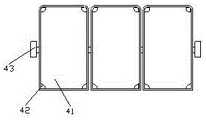
图1为本发明一种新型艺术设计专用展示装置的结构示意图;Fig. 1 is the structural representation of a kind of new-type art design special-purpose display device of the present invention;
图2为本发明展示结构的结构示意图;2 is a schematic structural diagram of a display structure of the present invention;
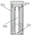
图3为本发明活动结构的结构示意图;Fig. 3 is the structural representation of the movable structure of the present invention;
图4为本发明滑动结构的结构示意图;Fig. 4 is the structural schematic diagram of the sliding structure of the present invention;
图5为本发明限位结构的结构示意图;Fig. 5 is the structural schematic diagram of the limiting structure of the present invention;
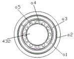
图6为本发明转动结构的结构示意图;Fig. 6 is the structural schematic diagram of the rotating structure of the present invention;
图7为本发明调节盘的结构示意图;Fig. 7 is the structural schematic diagram of the adjusting disc of the present invention;
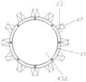
图8为本发明卡齿结构的结构示意图。FIG. 8 is a schematic structural diagram of the tooth structure of the present invention.
图中: 万向轮-1、底架-2、支架-3、展示结构-4、连接架-5、展示板-41、限位块-42、活动结构-43、滑动结构-431、转轴-432、转动结构-433、安装板-434、外框-31a、活动架-31b、安装块-31c、限位结构-31d、嵌入框-d1、卡杆-d2、弹簧-d3、滚珠体-d4、导轨-d5、调节盘-33a、连接块-33b、内卡槽-33c、卡齿结构-33d、盘体-a1、活动框-a2、内弹簧-a3、联动架-a4、滚珠-a5、卡盘-z1、卡齿-z2、倾斜块-z3。In the picture: Universal wheel-1, bottom frame-2, bracket-3, display structure-4, connecting frame-5, display board-41, limit block-42, movable structure-43, sliding structure-431, rotating shaft -432, rotating structure-433, mounting plate-434, outer frame-31a, movable frame-31b, mounting block-31c, limit structure-31d, embedded frame-d1, clamping rod-d2, spring-d3, ball body -d4, guide rail-d5, adjusting disc-33a, connecting block-33b, inner slot-33c, tooth structure-33d, disc body-a1, movable frame-a2, inner spring-a3, linkage frame-a4, ball -a5, chuck-z1, tooth-z2, tilt block-z3.
具体实施方式Detailed ways
为使本发明实现的技术手段、创作特征、达成目的与功效易于明白了解,下面结合具体实施方式,进一步阐述本发明。In order to make the technical means, creative features, achievement goals and effects realized by the present invention easy to understand, the present invention will be further described below with reference to the specific embodiments.
实施例一:请参阅图1-图5,本发明具体实施例如下:Embodiment 1: Please refer to FIG. 1-FIG. 5, the specific embodiments of the present invention are as follows:
其结构包括万向轮1、底架2、支架3、展示结构4、连接架5,所述万向轮1竖直安装于底架2下端四角并且采用铰链连接,所述支架3倾斜安装于底架2上端并且相焊接,所述展示结构4嵌入于支架3之间并且采用活动连接,所述连接架5水平安装于支架3之间并且采用固定连接;所述展示结构4包括展示板41、限位块42、活动结构43,所述展示板41安装于活动结构43外侧并且相卡接,所述限位块42安装于展示板41内侧四角并且采用机械连接,所述活动结构43水平嵌入于支架3之间并且采用活动连接。Its structure includes a universal wheel 1, a
参阅图3,所述活动结构43包括滑动结构431、转轴432、转动结构433、安装板434,所述转轴432嵌入安装于滑动结构431之间并且相卡接,所述转动结构433安装于转轴432外侧并且采用机械连接,所述安装板434套设于转动结构433外侧并且相卡接,在滑出的同时,可进行旋转,来调节展示板41的位置,更好的进行艺术设计观察。Referring to FIG. 3 , the
参阅图4,所述滑动结构431包括外框31a、活动架31b、安装块31c、限位结构31d,所述活动架31b嵌入安装于外框31a内侧并且采用活动连接,所述安装块31c固定于活动架31b前端并且相焊接,所述限位结构31d安装于活动架31b外侧并且与外框31a内侧相卡接,向外倾斜滑出展开,并与进行位置的调节观察。Referring to FIG. 4 , the
参阅图5,所述限位结构31d包括嵌入框d1、卡杆d2、弹簧d3、滚珠体d4、导轨d5,所述卡杆d2嵌入安装于嵌入框d1内侧并且相焊接,所述弹簧d3套设于卡杆d2外侧并且两端分别抵在嵌入框d1与滚珠体d4之间,所述导轨d5嵌入于嵌入框d1内侧并且采用固定连接,所述滚珠体d4活动连接于嵌入框d1内侧并且与导轨d5滑动连接,在进行滑动时便于进行滚动的限位,进行位置上的固定,便于更好的进行观察。Referring to FIG. 5 , the
参阅图5,所述卡杆d2左端为弧形结构并且由上至下逐渐向外延伸,所述卡杆d2贯穿于滚珠体d4右端并且之间静止时留有空隙,在活动架31b向外滑出时增加与卡杆d2的接触,减少滚珠体d4的滚动,便于进行限位,而在向内移动时,减少了之间的接触,来更好的使滚珠体d4进行滚动,便于收起。Referring to FIG. 5 , the left end of the clamping rod d2 is an arc-shaped structure and gradually extends outward from top to bottom. The clamping rod d2 penetrates through the right end of the ball body d4 and leaves a gap when it is stationary, and the movable frame 31b outwards When sliding out, the contact with the clamping rod d2 is increased, the rolling of the ball body d4 is reduced, and the limit is facilitated. When moving inward, the contact between the two is reduced, so that the ball body d4 can be rolled better, which is convenient for retraction. rise.
基于上述实施例,具体工作原理如下:Based on the above embodiment, the specific working principle is as follows:
将艺术设计的展品放置于展示板41上端并利用限位块42进行限制,即可推动支架3,使底架2下端的万向轮1在路面上进行移动来移动到合适的位置上,在进行展品的展览观察中,需要对其角度进行调节时,拉动展示板41,此时与其连接的活动结构43将向外侧移动,而使滑动结构431受力,转轴432之间的安装块31c将倾斜向下移动而带动活动架31b,此时的活动架31b将在外框31a内侧向外滑动并作用于之间的限位结构31d上,滚珠体d4将压缩弹簧d3并受到卡杆d2的限制而缓慢移动,在横向长度足够时即可停止拉动,而活动架31b受到展品向下的重力而挤压滚珠体d4卡在卡杆d2上,进而限制住位置,而需要对展品进行转向时,拨动展示板41来使背端的转动结构433绕着转轴432进行转动,来进行展览观察,而需要复位时,按上述反向操作即可将展示板41收回。Place the artistically designed exhibit on the upper end of the
实施例二:请参阅图3、图6-图8,本发明具体实施例如下:Embodiment 2: Please refer to Fig. 3, Fig. 6-Fig. 8, the specific embodiment of the present invention is as follows:
所述活动结构43包括滑动结构431、转轴432、转动结构433、安装板434,所述转轴432嵌入安装于滑动结构431之间并且相卡接,所述转动结构433安装于转轴432外侧并且采用机械连接,所述安装板434套设于转动结构433外侧并且相卡接。The
参阅图6,所述转动结构433包括调节盘33a、连接块33b、内卡槽33c、卡齿结构33d,所述连接块33b设于调节盘33a外侧并且均匀分布,所述内卡槽33c凹陷于调节盘33a内侧并且为一体化结构,所述卡齿结构33d嵌入安装于调节盘33a内侧并且与内卡槽33c相卡接,所述卡齿结构33d安装于转轴432外侧并且采用机械连接,进行调节转动,并在合适的位置卡住,进行停留观察。Referring to FIG. 6 , the rotating
参阅图7,所述调节盘33a包括盘体a1、活动框a2、内弹簧a3、联动架a4、滚珠a5,所述活动框a2嵌入安装于盘体a1内侧并且采用活动连接,所述内弹簧a3嵌入于活动框a2内侧并且相卡接,所述联动架a4水平安装于活动框a2下端并且相焊接,所述联动架a4安装于转轴432外侧并且相卡接,进行侧向的移动,来便于接触限制进行旋转,而内弹簧a3帮助其及时的进行复位,而重新限制。Referring to FIG. 7 , the adjustment disc 33a includes a disc body a1, a movable frame a2, an inner spring a3, a linkage frame a4, and a ball a5. The movable frame a2 is embedded in the inner side of the disc body a1 and is movably connected. The inner spring a3 is embedded in the inner side of the movable frame a2 and connected to each other, the linkage frame a4 is horizontally installed on the lower end of the movable frame a2 and welded to each other, and the linkage frame a4 is installed on the outside of the
参阅图8,所述卡齿结构33d包括卡盘z1、卡齿z2、倾斜块z3,所述卡盘z1安装于转轴432外侧并且采用机械连接,所述卡齿z2设于卡盘z1外侧并且为一体化结构,所述倾斜块z3安装于卡齿z2前端并且相焊接,所述倾斜块z3由卡齿z2外侧逐渐向内侧延伸汇聚,便于与内卡槽33c相卡接,进行角度上的限制。Referring to FIG. 8 , the clamping
基于上述实施例,具体工作原理如下:Based on the above embodiment, the specific working principle is as follows:
在转轴432随着滑动结构431滑出时,上端的转动结构433也将随之移动出来,在需要角度的调节时,首先压动转动结构433进行侧向的移动,活动框a2向内侧移动并压缩内弹簧a3,来使盘体a1进行侧向的移动,此时上端的内卡槽33c将离开卡齿结构33d,即可进行转动来使盘体a1内侧的滚珠a5在转轴432外侧进行滚动,而调节其的角度,在处于合适位置时,解除外力,来使内弹簧a3复位,盘体a1侧向回位,内卡槽33c将抵在倾斜块z3并顺着其斜面滑至卡齿z2外侧,实现角度的限制,即可完成角度的调节。When the
本发明解决了现有技术由于在艺术设计的展示中产品众多,进而需要进行紧密的排布,使其在进行角度变化的观察时,需要频繁的挪动自己的位置来改变视线进行观察,造成参展人员的疲惫,而降低观察艺术设计展品的数量的问题,本发明通过上述部件的互相组合,在展示板外侧设置了活动结构,转轴之间的安装块将倾斜向下移动而带动活动架,此时的活动架将在外框内侧向外滑动并作用于之间的限位结构上,滚珠体将压缩弹簧并受到卡杆的限制而缓慢移动,在横向长度足够时即可停止拉动,而活动架受到展品向下的重力而挤压滚珠体卡在卡杆上,进而限制住位置,可进行位置上的调节来进行展品的观察,更好的进行多数量的观察;在转轴外侧设置了转动结构,压动转动结构进行侧向的移动,活动框向内侧移动并压缩内弹簧,来使盘体进行侧向的移动,此时上端的内卡槽将离开卡齿结构,即可进行转动来使盘体内侧的滚珠在转轴外侧进行滚动,而调节其的角度,在处于合适位置时,解除外力,来使内弹簧复位,盘体侧向回位,内卡槽将抵在倾斜块并顺着其斜面滑至卡齿外侧,实现角度的限制,使位置进行调节限制,更好的进行位置的改变来进行观察,减少了挪动位置造成的疲惫,提高了观察艺术设计展品的数量。The present invention solves the problem that in the prior art, since there are many products in the display of artistic design, it needs to be closely arranged, so that when observing the angle change, it needs to move the position frequently to change the line of sight for observation, causing the exhibition To reduce the fatigue of personnel and reduce the number of observed art and design exhibits, the present invention sets a movable structure on the outside of the display board through the combination of the above components, and the installation block between the rotating shafts will move downward obliquely to drive the movable frame. When the movable frame will slide outwards on the inside of the outer frame and act on the limit structure between, the ball body will compress the spring and be restricted by the clamping rod and move slowly, when the horizontal length is sufficient, it can stop pulling, and the movable frame Due to the downward gravity of the exhibits, the ball body is squeezed and stuck on the clamping rod, thereby limiting the position. The position can be adjusted to observe the exhibits, and a large number of observations can be made better; a rotating structure is set on the outside of the rotating shaft. , press the rotating structure to move laterally, the movable frame moves inward and compresses the inner spring to make the disk body move laterally, at this time, the inner card slot at the upper end will leave the card tooth structure, and it can be rotated to make the plate body move laterally. The ball on the inside of the disc rolls on the outside of the rotating shaft, and adjusts its angle. When it is in a proper position, the external force is released to reset the inner spring, the disc body is returned to the side, and the inner slot will touch the inclined block and follow the The inclined surface slides to the outside of the card teeth to limit the angle, so that the position can be adjusted and restricted, and the position can be better changed for observation, reducing the fatigue caused by moving the position, and increasing the number of observed art and design exhibits.
以上显示和描述了本发明的基本原理和主要特征和本发明的优点,对于本领域技术人员而言,显然本发明不限于上述示范性实施例的细节,而且在不背离本发明的精神或基本特征的情况下,能够以其他的具体形式实现本发明。因此,无论从哪一点来看,均应将实施例看作是示范性的,而且是非限制性的,本发明的范围由所附权利要求而不是上述说明限定,因此旨在将落在权利要求的等同要件的含义和范围内的所有变化囊括在本发明内。不应将权利要求中的任何附图标记视为限制所涉及的权利要求。While the basic principles and main features and advantages of the present invention have been shown and described above, it will be apparent to those skilled in the art that the present invention is not limited to the details of the above-described exemplary embodiments, but without departing from the spirit or essential aspects of the present invention. In the case of the characteristic features, the present invention can be implemented in other specific forms. Therefore, the embodiments are to be regarded in all respects as illustrative and not restrictive, and the scope of the invention is to be defined by the appended claims rather than the foregoing description, which are therefore intended to fall within the scope of the claims. All changes within the meaning and range of the equivalents of , are included in the present invention. Any reference signs in the claims shall not be construed as limiting the involved claim.
此外,应当理解,虽然本说明书按照实施方式加以描述,但并非每个实施方式仅包含一个独立的技术方案,说明书的这种叙述方式仅仅是为清楚起见,本领域技术人员应当将说明书作为一个整体,各实施例中的技术方案也可以经适当组合,形成本领域技术人员可以理解的其他实施方式。In addition, it should be understood that although this specification is described in terms of embodiments, not each embodiment only includes an independent technical solution, and this description in the specification is only for the sake of clarity, and those skilled in the art should take the specification as a whole , the technical solutions in each embodiment can also be appropriately combined to form other implementations that can be understood by those skilled in the art.
Claims (8)
Priority Applications (1)
| Application Number | Priority Date | Filing Date | Title |
|---|---|---|---|
| CN202010837215.4ACN111972913B (en) | 2020-08-19 | 2020-08-19 | A new type of special display device for art design |
Applications Claiming Priority (1)
| Application Number | Priority Date | Filing Date | Title |
|---|---|---|---|
| CN202010837215.4ACN111972913B (en) | 2020-08-19 | 2020-08-19 | A new type of special display device for art design |
Publications (2)
| Publication Number | Publication Date |
|---|---|
| CN111972913Atrue CN111972913A (en) | 2020-11-24 |
| CN111972913B CN111972913B (en) | 2022-05-13 |
Family
ID=73435643
Family Applications (1)
| Application Number | Title | Priority Date | Filing Date |
|---|---|---|---|
| CN202010837215.4AActiveCN111972913B (en) | 2020-08-19 | 2020-08-19 | A new type of special display device for art design |
Country Status (1)
| Country | Link |
|---|---|
| CN (1) | CN111972913B (en) |
Cited By (1)
| Publication number | Priority date | Publication date | Assignee | Title |
|---|---|---|---|---|
| CN113332475A (en)* | 2021-04-30 | 2021-09-03 | 戴丽云 | Department of general surgery's surgical instruments disinfecting equipment |
Citations (19)
| Publication number | Priority date | Publication date | Assignee | Title |
|---|---|---|---|---|
| DE4036555A1 (en)* | 1990-11-16 | 1992-05-21 | Francesco Truncale | Terminal support stand for monitor - allows adjustment of height and angle to suit user using base frame linked to board |
| US5638579A (en)* | 1996-09-05 | 1997-06-17 | Tenney; Kenneth B. | Friction tilt mechanism |
| KR19990075218A (en)* | 1998-03-18 | 1999-10-15 | 윤종용 | Monitor with stands structure incorporating speaker |
| TW404638U (en)* | 1999-03-18 | 2000-09-01 | Chiou Huei Min | Plane monitor used foot seat |
| CN201185091Y (en)* | 2008-02-18 | 2009-01-21 | 广州毅昌科技股份有限公司 | Installation foundation for multifunctional flat panel display product |
| JP2009124736A (en)* | 1997-08-01 | 2009-06-04 | Scientific-Atlanta Inc | Encryption apparatus used in conditional access system |
| CN205457629U (en)* | 2016-01-14 | 2016-08-17 | 吉林动画学院 | Works show shelf for art design |
| CN106235800A (en)* | 2016-08-25 | 2016-12-21 | 天津中利网络科技有限公司 | A kind of device showing commodity for Multifunction ecommerce |
| EP3447754A1 (en)* | 2017-07-11 | 2019-02-27 | Huasun Technology Co., Ltd. | Oscillating display device |
| CN209370741U (en)* | 2019-01-03 | 2019-09-10 | 深圳市华诚设计开发有限公司 | A kind of adjustable two separate display device |
| CN209591200U (en)* | 2018-12-18 | 2019-11-05 | 青岛科技大学 | A kind of art design teaching displaying device |
| CN209708537U (en)* | 2019-05-23 | 2019-11-29 | 戴泳良 | A kind of propagandizing device of power marketing extension |
| CN209801399U (en)* | 2019-04-12 | 2019-12-17 | 韩雨彤 | Desk lamp is with adjusting support with fixed knot constructs |
| CN209980544U (en)* | 2019-04-11 | 2020-01-21 | 杨婵婵 | Rotary teaching display board for medical nursing major |
| CN210920876U (en)* | 2019-11-15 | 2020-07-03 | 郑州金之源电子科技有限公司 | Display is with installing support of angle regulation of being convenient for |
| CN211016392U (en)* | 2019-10-06 | 2020-07-14 | 湖南高速铁路职业技术学院 | A adjustable angle type show shelf for think political affairs education |
| CN211062279U (en)* | 2019-12-31 | 2020-07-21 | 大连海洋大学 | Tongue flipping method display device in Russian teaching |
| CN211124926U (en)* | 2020-02-04 | 2020-07-28 | 郜发磊 | Employment information display rack convenient for higher education and capable of being conveniently inserted with information display board |
| CN211269701U (en)* | 2019-06-24 | 2020-08-18 | 山东商业职业技术学院 | Art design display device |
- 2020
- 2020-08-19CNCN202010837215.4Apatent/CN111972913B/enactiveActive
Patent Citations (19)
| Publication number | Priority date | Publication date | Assignee | Title |
|---|---|---|---|---|
| DE4036555A1 (en)* | 1990-11-16 | 1992-05-21 | Francesco Truncale | Terminal support stand for monitor - allows adjustment of height and angle to suit user using base frame linked to board |
| US5638579A (en)* | 1996-09-05 | 1997-06-17 | Tenney; Kenneth B. | Friction tilt mechanism |
| JP2009124736A (en)* | 1997-08-01 | 2009-06-04 | Scientific-Atlanta Inc | Encryption apparatus used in conditional access system |
| KR19990075218A (en)* | 1998-03-18 | 1999-10-15 | 윤종용 | Monitor with stands structure incorporating speaker |
| TW404638U (en)* | 1999-03-18 | 2000-09-01 | Chiou Huei Min | Plane monitor used foot seat |
| CN201185091Y (en)* | 2008-02-18 | 2009-01-21 | 广州毅昌科技股份有限公司 | Installation foundation for multifunctional flat panel display product |
| CN205457629U (en)* | 2016-01-14 | 2016-08-17 | 吉林动画学院 | Works show shelf for art design |
| CN106235800A (en)* | 2016-08-25 | 2016-12-21 | 天津中利网络科技有限公司 | A kind of device showing commodity for Multifunction ecommerce |
| EP3447754A1 (en)* | 2017-07-11 | 2019-02-27 | Huasun Technology Co., Ltd. | Oscillating display device |
| CN209591200U (en)* | 2018-12-18 | 2019-11-05 | 青岛科技大学 | A kind of art design teaching displaying device |
| CN209370741U (en)* | 2019-01-03 | 2019-09-10 | 深圳市华诚设计开发有限公司 | A kind of adjustable two separate display device |
| CN209980544U (en)* | 2019-04-11 | 2020-01-21 | 杨婵婵 | Rotary teaching display board for medical nursing major |
| CN209801399U (en)* | 2019-04-12 | 2019-12-17 | 韩雨彤 | Desk lamp is with adjusting support with fixed knot constructs |
| CN209708537U (en)* | 2019-05-23 | 2019-11-29 | 戴泳良 | A kind of propagandizing device of power marketing extension |
| CN211269701U (en)* | 2019-06-24 | 2020-08-18 | 山东商业职业技术学院 | Art design display device |
| CN211016392U (en)* | 2019-10-06 | 2020-07-14 | 湖南高速铁路职业技术学院 | A adjustable angle type show shelf for think political affairs education |
| CN210920876U (en)* | 2019-11-15 | 2020-07-03 | 郑州金之源电子科技有限公司 | Display is with installing support of angle regulation of being convenient for |
| CN211062279U (en)* | 2019-12-31 | 2020-07-21 | 大连海洋大学 | Tongue flipping method display device in Russian teaching |
| CN211124926U (en)* | 2020-02-04 | 2020-07-28 | 郜发磊 | Employment information display rack convenient for higher education and capable of being conveniently inserted with information display board |
Cited By (1)
| Publication number | Priority date | Publication date | Assignee | Title |
|---|---|---|---|---|
| CN113332475A (en)* | 2021-04-30 | 2021-09-03 | 戴丽云 | Department of general surgery's surgical instruments disinfecting equipment |
Also Published As
| Publication number | Publication date |
|---|---|
| CN111972913B (en) | 2022-05-13 |
Similar Documents
| Publication | Publication Date | Title |
|---|---|---|
| CN115565449B (en) | Multimedia display stand | |
| CN111972913B (en) | A new type of special display device for art design | |
| CN206726697U (en) | A kind of house ads board lamp box | |
| CN211475389U (en) | Liftable projecting apparatus | |
| CN113506525A (en) | Education and training is with portable folding door type exhibition frame | |
| CN208421489U (en) | A kind of still life photography platform | |
| CN216089849U (en) | Showcase with adjusting function | |
| CN211092362U (en) | Opening-closing type office table | |
| CN201650956U (en) | a telescopic arm | |
| CN211826885U (en) | A projection display stand for visual communication | |
| CN211673520U (en) | Work of fine arts display device | |
| CN210894980U (en) | A curtain fixing device for informatization teaching | |
| CN211657623U (en) | Multimedia teaching platform | |
| CN210865522U (en) | Automobile service and marketing show stand with rotation function | |
| CN114019747A (en) | Animation shooting table with height-adjustable function | |
| CN223051846U (en) | Information display roll-over stand for exhibition center | |
| CN219331212U (en) | Improved display rack | |
| CN222462342U (en) | An exhibition hall display rack that is easy to install | |
| CN216565232U (en) | A bracket with a quick-adjusting height structure for e-commerce live broadcast | |
| CN220174854U (en) | Exhibition showing stand capable of rotating for showing | |
| CN220459053U (en) | Door and window showing stand for exhibition | |
| CN222255714U (en) | A lockable touch screen support assembly | |
| CN218832437U (en) | a display stand | |
| CN220529695U (en) | Display rack convenient to adjust | |
| CN222826059U (en) | A new media publicity display stand |
Legal Events
| Date | Code | Title | Description |
|---|---|---|---|
| PB01 | Publication | ||
| PB01 | Publication | ||
| SE01 | Entry into force of request for substantive examination | ||
| SE01 | Entry into force of request for substantive examination | ||
| GR01 | Patent grant | ||
| GR01 | Patent grant |