Movatterモバイル変換


[0]ホーム

URL:


CN111971449A - Providing mechanical barriers in a single feed - Google Patents

Providing mechanical barriers in a single feed
Download PDF

Info

Publication number
CN111971449A
CN111971449ACN201880092349.9ACN201880092349ACN111971449ACN 111971449 ACN111971449 ACN 111971449ACN 201880092349 ACN201880092349 ACN 201880092349ACN 111971449 ACN111971449 ACN 111971449A
Authority
CN
China
Prior art keywords
wellbore
barrier system
string
running tool
deep
Prior art date
Legal status (The legal status is an assumption and is not a legal conclusion. Google has not performed a legal analysis and makes no representation as to the accuracy of the status listed.)
Pending
Application number
CN201880092349.9A
Other languages
Chinese (zh)
Inventor
D·A·多克威勒
G·M·豪伊特
W·E·斯坦德里奇
Current Assignee (The listed assignees may be inaccurate. Google has not performed a legal analysis and makes no representation or warranty as to the accuracy of the list.)
Halliburton Energy Services Inc
Original Assignee
Halliburton Energy Services Inc
Priority date (The priority date is an assumption and is not a legal conclusion. Google has not performed a legal analysis and makes no representation as to the accuracy of the date listed.)
Filing date
Publication date
Application filed by Halliburton Energy Services IncfiledCriticalHalliburton Energy Services Inc
Publication of CN111971449ApublicationCriticalpatent/CN111971449A/en
Pendinglegal-statusCriticalCurrent

Links

Images

Classifications

Landscapes

Abstract

Translated fromChinese

一种作业可能需要使用多个屏障来隔离井筒。可在单次送入井筒管柱期间将单次送入多屏障系统部署在井筒中,以将第一屏障定位在所述井筒中的第一深度处并且将第二屏障定位在所述井筒中的所述第一屏障上方的第二深度处。所述第一屏障联接到第一送入工具。井筒管柱段将所述第一送入工具联接到所述第二屏障。所述第二屏障联接到第二送入工具,所述第二送入工具联接到所述井筒管柱。在独立地将所述第一屏障设置在所述第一深度处之前锁定所述第二屏障,以防止在到达所述第二深度之前设置所述第二屏障。在单次送入中设置两个屏障增加了作业的效率,包括减少了完成所述作业的成本和时间。

Figure 201880092349

An operation may require the use of multiple barriers to isolate the wellbore. A single-run multi-barrier system can be deployed in a wellbore during a single-run wellbore string to position a first barrier at a first depth in the wellbore and position a second barrier in the wellbore at a second depth above the first barrier. The first barrier is coupled to the first running tool. A wellbore tubular section couples the first running tool to the second barrier. The second barrier is coupled to a second running tool coupled to the wellbore string. The second barrier is locked before the first barrier is independently positioned at the first depth to prevent the second barrier from being positioned until the second depth is reached. Having two barriers in a single feed increases the efficiency of the job, including reducing the cost and time to complete the job.

Figure 201880092349

Description

Translated fromChinese
在单次送入中设置机械屏障Set up mechanical barriers in a single feed

技术领域technical field

本发明涉及设置屏障,并且更具体来说,涉及在井筒中在单次送入中在两个或更多个不同深度处设置多个屏障。The present invention relates to providing barriers, and more particularly, to providing multiple barriers in a wellbore at two or more different depths in a single run.

背景技术Background technique

可在井筒内使用与生产碳氢化合物以及返修或维修井相关的广泛多种井下工具,诸如维修工具。在许多情形下,操作可要求将多个屏障引入到钻孔或井筒中,并且设置在井筒内的不同深度处以隔离井筒或地层的部分。许多运营商和政府规定要求在井筒中安装最少两个屏障。举例来说,可实施针对包括碳氢化合物生产的堵塞和放弃以及井喷预防的工作的若干类型的操作,这要求在井筒中安装多个屏障。通常,每个屏障必须在诸如钻杆或管柱等工具串上单独地送入到井筒中,并且可要求不同的工具来解锁和设置该屏障。举例来说,第一屏障可通过工具串送入到井筒中到达设置深度,进行设置,并且从井筒起出工具串。第二屏障连接至工具串,在井筒中送入并且设置在不同的设置深度处,该工具串从井中往回起出。每次安装屏障需要沿着井筒的至少两个行程,这增加了设备的损耗并且增加了机械故障的风险,以上两者都导致总工作完成时间和总工作成本的增加以及增加了附近人员的安全风险。A wide variety of downhole tools, such as workover tools, may be used in the wellbore associated with producing hydrocarbons and reworking or servicing wells. In many cases, operations may require the introduction of multiple barriers into the borehole or wellbore and placed at different depths within the wellbore to isolate portions of the wellbore or formation. Many operator and government regulations require a minimum of two barriers to be installed in the wellbore. For example, several types of operations may be performed for work including plugging and abandonment of hydrocarbon production and blowout prevention, which require the installation of multiple barriers in the wellbore. Typically, each barrier must be fed into the wellbore individually on a tool string such as drill pipe or tubing, and different tools may be required to unlock and set the barrier. For example, the first barrier can be run into the wellbore by the tool string to a setting depth, set, and the tool string is pulled from the wellbore. The second barrier is connected to a tool string, which is run in the wellbore and placed at different set-up depths, from which the tool string is drawn back out. Each installation of the barrier requires at least two strokes along the wellbore, which increases equipment wear and increases the risk of mechanical failure, both of which result in an increase in total work completion time and overall work cost, as well as increased safety for nearby personnel risk.

附图说明Description of drawings

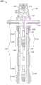
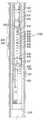
图1是根据本公开的一个或多个方面的操作环境中的单次送入多屏障系统的横截面视图。1 is a cross-sectional view of a single-pass multiple barrier system in an operating environment in accordance with one or more aspects of the present disclosure.

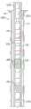
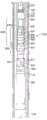
图2是根据本公开的一个或多个方面的具有设置在操作环境中的深设置屏障的单次送入多屏障系统的横截面视图。2 is a cross-sectional view of a single-entry multiple-barrier system with a deep-placed barrier disposed in an operating environment in accordance with one or more aspects of the present disclosure.

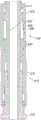
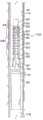
图3是根据本公开的一个或多个方面的具有设置在操作环境中的浅设置屏障的单次送入多屏障系统的横截面视图。3 is a cross-sectional view of a single-entry multiple-barrier system with shallowly-placed barriers disposed in an operating environment in accordance with one or more aspects of the present disclosure.

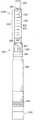
图4A是根据本公开的一个或多个方面的处于未设置位置的单次送入多屏障系统的浅设置屏障的示意图。4A is a schematic illustration of a shallow set barrier of a single-pass multi-barrier system in an unset position in accordance with one or more aspects of the present disclosure.

图4B是根据本公开的一个或多个方面的处于设置位置的单次送入多屏障系统的浅设置屏障的示意图。4B is a schematic illustration of a shallow set-up barrier of a single-pass multi-barrier system in a set-up position in accordance with one or more aspects of the present disclosure.

图5A是根据本公开的一个或多个方面的处于未设置位置的单次送入多屏障系统的深设置屏障的示意图。5A is a schematic illustration of a deep set barrier of a single-pass multi-barrier system in an unset position in accordance with one or more aspects of the present disclosure.

图5B是根据本公开的一个或多个方面的处于设置位置的单次送入多屏障系统的深设置屏障的示意图。5B is a schematic illustration of a deep set-up barrier of a single-pass multi-barrier system in a set-up position in accordance with one or more aspects of the present disclosure.

图6A是根据本公开的一个或多个方面的处于锁定位置的浅设置屏障系统的锁定狭槽组件的横截面视图。6A is a cross-sectional view of a locking slot assembly of a shallow setting barrier system in a locked position in accordance with one or more aspects of the present disclosure.

图6B是根据本公开的一个或多个方面的处于解锁位置的浅设置屏障系统的锁定狭槽组件的横截面视图。6B is a cross-sectional view of a locking slot assembly of a shallow setting barrier system in an unlocked position in accordance with one or more aspects of the present disclosure.

图7A是根据本公开的一个或多个方面的处于锁定位置的浅设置屏障的锁定狭槽组件的横截面视图。7A is a cross-sectional view of a locking slot assembly of a shallowly disposed barrier in a locked position in accordance with one or more aspects of the present disclosure.

图7B是根据本公开的一个或多个方面的处于解锁位置的浅设置屏障的锁定狭槽组件的横截面视图。7B is a cross-sectional view of a locking slot assembly of a shallowly disposed barrier in an unlocked position in accordance with one or more aspects of the present disclosure.

图8A是根据本公开的一个或多个方面的处于锁定位置的浅设置屏障的锁定狭槽组件的侧视图。8A is a side view of a locking slot assembly of a shallowly positioned barrier in a locked position in accordance with one or more aspects of the present disclosure.

图8B是根据本公开的一个或多个方面的处于解锁位置的浅设置屏障的锁定狭槽组件的侧视图。8B is a side view of the locking slot assembly of the shallowly disposed barrier in an unlocked position in accordance with one or more aspects of the present disclosure.

图9是根据本公开的一个或多个方面的深设置屏障系统的心轴部件和滑动锁定部件的示意性侧视图。9 is a schematic side view of a mandrel component and a slide lock component of a deep set barrier system in accordance with one or more aspects of the present disclosure.

图10是根据本公开的一个或多个方面的深设置屏障系统的顶部适配器和打捞筒部件的示意性横截面侧视图。10 is a schematic cross-sectional side view of a top adapter and overshot component of a deep set barrier system in accordance with one or more aspects of the present disclosure.

图11是根据本公开的一个或多个方面的处于锁定配置的深设置屏障系统的局部横截面示意性侧视图。11 is a partial cross-sectional schematic side view of a deep set barrier system in a locked configuration in accordance with one or more aspects of the present disclosure.

图12是根据本公开的一个或多个方面的处于连接和锁定配置的深设置屏障系统的局部横截面示意性侧视图。12 is a partial cross-sectional schematic side view of a deep set barrier system in a connected and locked configuration in accordance with one or more aspects of the present disclosure.

图13是根据本公开的一个或多个方面的处于连接和解锁配置的深设置屏障系统的局部横截面示意性侧视图。13 is a partial cross-sectional schematic side view of a deep set barrier system in a connected and unlocked configuration in accordance with one or more aspects of the present disclosure.

图14是处于释放和解锁配置的深设置屏障系统的局部横截面示意性侧视图。14 is a partial cross-sectional schematic side view of the deep set barrier system in a released and unlocked configuration.

图15是处于释放配置的深设置屏障系统的局部横截面示意性侧视图。15 is a partial cross-sectional schematic side view of a deep set barrier system in a release configuration.

图16是处于释放配置的深设置屏障系统的局部横截面示意性侧视图。16 is a partial cross-sectional schematic side view of the deep set barrier system in a release configuration.

图17是说明根据本公开的一个或多个方面的用于设置单次送入多屏障系统的方法的流程图。17 is a flow chart illustrating a method for setting up a single entry multiple barrier system in accordance with one or more aspects of the present disclosure.

具体实施方式Detailed ways

在后面的附图和描述中,类似的部分通常被标记有相同的参考数字。在附图中描述和示出了具体实施方案,应理解,本公开将被视为本发明的原理的范例并且无意限制本文所说明和描述的本发明。应完全认识到,可单独地或者以任何合适的组合采用全文论述的实施方案的不同教导来产生所要的结果。In the drawings and descriptions that follow, like parts are generally marked with the same reference numerals. While specific embodiments are described and illustrated in the drawings, it is to be understood that this disclosure is to be considered as exemplifying the principles of the invention and is not intended to limit the invention illustrated and described herein. It is fully appreciated that the various teachings of the embodiments discussed throughout can be employed alone or in any suitable combination to produce the desired results.

对于特定井下操作,需要屏障或隔离装置在井筒中送入以隔离井筒或地层的部分。举例来说,井的井喷预防(BOP)或放弃可要求多个屏障在井筒中送入以隔离井筒或地层的部分。一般来说,对于部署在井下工具上的屏障,一旦设置一个屏障,便设置附接到油管柱或井筒管柱的所有屏障。需要在不同深度处设置多个屏障的操作需要在井筒中的多次送入。举例来说,使包括屏障的井下工具在井筒中送入到指定深度,并且当到达所述深度时,设置屏障。取回所述井下工具并且使另一屏障在同一或不同的井下工具上在井筒中送入。同样,一旦到达指定深度,便设置屏障并且取回井下工具。因为设置多个屏障需要多次送入,所以在不同深度处放置多个屏障需要大量时间,这增加了操作的总成本并且由于与设备多次接触而增加了附近人员的风险。For certain downhole operations, barriers or isolation devices are required to be run in the wellbore to isolate portions of the wellbore or formation. For example, blowout prevention (BOP) or abandonment of a well may require multiple barriers to be run in the wellbore to isolate portions of the wellbore or formation. Generally, for barriers deployed on downhole tools, once one barrier is set, all barriers attached to the tubing string or wellbore string are set. Operations that require multiple barriers at different depths require multiple runs in the wellbore. For example, a downhole tool including a barrier is run in a wellbore to a specified depth, and when the depth is reached, the barrier is placed. The downhole tool is retrieved and another barrier is run in the wellbore on the same or a different downhole tool. Also, once the specified depth is reached, the barrier is set up and the downhole tool is retrieved. Because setting up multiple barriers requires multiple feeds, placing multiple barriers at different depths requires significant time, which increases the overall cost of the operation and increases the risk to nearby personnel due to multiple contact with the equipment.

本发明提供了需要在井筒中设置多个屏障或隔离装置以隔离井筒或地层的部分的井下操作的增加的效率。使用井下工具的单次送入来提供具有可设置在井筒中的多个屏障的单次送入多屏障系统减轻了对多次送入的需要。在单次送入中设置多个屏障减少了设备的损耗,减少了完成操作的时间,并且通过使附近人员与所需的设备的接触减到最少而增加了安全性。举例来说,深设置屏障可连接至取回工具,所述取回工具连接至浅设置屏障,所述浅设置屏障也连接至井下工具的取回工具。可在单次送入中将所述深设置屏障和所述浅设置屏障两者都在井下部署,因为所述浅设置屏障一直被锁定,直到在已经设置了所述深设置屏障之后。The present invention provides increased efficiency for downhole operations that require the placement of multiple barriers or isolation devices in the wellbore to isolate portions of the wellbore or formation. Using a single run of a downhole tool to provide a single run multi-barrier system with multiple barriers that can be placed in the wellbore alleviates the need for multiple runs. Having multiple barriers in a single run reduces equipment wear, reduces the time to complete operations, and increases safety by minimizing nearby personnel contact with the required equipment. For example, a deep set barrier may be connected to a retrieval tool, which is connected to a shallow set barrier, which is also connected to the retrieval tool of the downhole tool. Both the deep and shallow barriers can be deployed downhole in a single run because the shallow barriers are locked until after the deep barriers have been set.

图1是根据本公开的一个或多个方面的操作环境100中的单次送入多屏障系统150的横截面视图。操作环境100包括位于地面104上或周围的修井或钻机106(在本文一般称为钻机106)。钻机106延伸经过井筒114并且围绕井筒114延伸,所述井筒穿透地下地层102。举例来说,钻机106可定位并装备成用于发现、勘探、生产碳氢化合物或它们的任何组合。在一个或多个实施方案中,钻机106可定位并装备成用于井筒114的完井或放弃(或以上两者)或BOP。井筒114可与地面104成任何角度或偏差而延伸到地下地层102中。1 is a cross-sectional view of a single-passmulti-barrier system 150 in anoperating environment 100 in accordance with one or more aspects of the present disclosure. Theoperating environment 100 includes a workover or drilling rig 106 (generally referred to herein as the drilling rig 106 ) located on or around the surface 104 .Drilling rig 106 extends through and aroundwellbore 114 , which penetratessubterranean formation 102 . For example, drillingrig 106 may be positioned and equipped for discovery, exploration, production of hydrocarbons, or any combination thereof. In one or more embodiments, drillingrig 106 may be positioned and equipped for completion or abandonment (or both) or BOP ofwellbore 114 . Thewellbore 114 may extend into thesubterranean formation 102 at any angle or deviation from the surface 104 .

钻机106可包括井架108和钻台110,通过所述井架和所述钻台,井筒管柱从钻机106向下延伸到井筒114中。钻机106可包括驱动机构118的马达116。机构118可包括绞车、滚筒、曲柄或适合于将井筒管柱120部署在井筒114中以及从所述井筒取回井筒管柱的任何其他装置。在一个或多个实施方案中,井筒114可包括延伸井筒114的长度以形成环空126的套管128或任何其他衬管。Drillingrig 106 may include aderrick 108 and adrill floor 110 through which a wellbore string extends down fromrig 106 intowellbore 114 .Drill 106 may includemotor 116 that drivesmechanism 118 . Themechanism 118 may include a drawworks, drum, crank, or any other device suitable for deploying thewellbore string 120 in thewellbore 114 and retrieving the wellbore string from the wellbore. In one or more embodiments, thewellbore 114 may include acasing 128 or any other liner extending the length of thewellbore 114 to form theannulus 126 .

井筒管柱120可包括一个或多个区段,包括(但不限于)诸如井筒管柱段120A和井筒管柱段120B等一个或多个部分。井筒管柱120可包括钻杆、工具串、油管柱、工作管柱、油管、钻柱或联接在一起以将一个或多个井下工具部署在井筒114内的任何其他管路,例如,单次送入多屏障系统150。在一个或多个实施方案中,单次送入多屏障系统150部署在环空126中。井筒管柱段120A可联接到单次送入多屏障系统150。井筒管柱120可包括联接在一起以形成井筒管柱120的任何数目个部分、段或长度。任何数目个井下工具可联接到井筒管柱120。井筒管柱120将单次送入多屏障系统150部署到井筒114中的所需深度。举例来说,井筒管柱段120A可联接到井筒管柱120的一个或多个其他段,并且井筒管柱段120B可联接到井筒管柱120的一个或多个其他段。井筒管柱120的任何一个或多个段可被旋拧或联接到井筒管柱120、一个或多个单次送入多屏障系统150、一个或多个其他井下工具或它们的任何组合的任何一个或多个其他段。Wellboretubular string 120 may include one or more sections including, but not limited to, one or more portions such as wellboretubular string section 120A and wellboretubular string section 120B.Wellbore string 120 may include drill pipe, tool string, tubing string, work string, tubing, drill string, or any other tubing coupled together to deploy one or more downhole tools withinwellbore 114, eg, a single pass into themulti-barrier system 150. In one or more embodiments, the single-passmulti-barrier system 150 is deployed in theannulus 126 . Thewellbore tubular section 120A may be coupled to a singlerun multi-barrier system 150 . The wellboretubular string 120 may include any number of sections, sections, or lengths that are coupled together to form the wellboretubular string 120 . Any number of downhole tools may be coupled to thewellbore string 120 . Thewellbore string 120 deploys the single-run multi-barrier system 150 to the desired depth in thewellbore 114 . For example, wellboretubular section 120A may be coupled to one or more other sections of wellboretubular string 120 , and wellboretubular string section 120B may be coupled to one or more other sections of wellboretubular string 120 . Any one or more sections of wellboretubular string 120 may be threaded or coupled to any of wellboretubular string 120, one or more single-run multi-barrier systems 150, one or more other downhole tools, or any combination thereof. one or more other segments.

在一个或多个实施方案中,单次送入多屏障系统150可包括处于井筒管柱120的远端处的深设置屏障系统112B和处于深设置屏障系统112B上方的浅设置屏障系统112A(统称为屏障系统112)、井筒管柱段120A和井筒管柱段120B。在一个或多个实施方案中,单次送入多屏障系统150可包括任何数目个屏障系统112。虽然在图1中绘示了单个井筒管柱段120A和单个井筒管柱段120B,但本公开预期任何数目个井筒管柱段120A和120B。浅设置屏障系统112A包括送入工具122A和隔离装置124A,例如,浅设置屏障。深设置屏障系统112B包括送入工具122B和隔离装置124B,例如深设置屏障。在一个或多个实施方案中,隔离装置124A和124B可包括桥塞、封隔器、屏障阀或任何其他隔离装置。在一个或多个实施方案中,井筒管柱段120A联接到送入工具122A,并且井筒管柱段120B联接到送入工具122B和浅设置屏障系统112A,其中送入工具122A和122B统称为送入工具122。送入工具122A联接到隔离装置124A,并且送入工具122B联接到隔离装置124B,其中隔离装置124A和124B统称为隔离装置124。井筒管柱段120B将隔离装置124A联接到送入工具122B。In one or more embodiments, the single-run multi-barrier system 150 may include a deep-set barrier system 112B at the distal end of the wellboretubular string 120 and a shallow-set barrier system 112A above the deep-set barrier system 112B (collectively referred to as the are barrier system 112),wellbore tubular section 120A, and wellboretubular section 120B. In one or more embodiments, the single-feed multi-barrier system 150 may include any number of barrier systems 112 . Although a singlewellbore tubular section 120A and a singlewellbore tubular section 120B are depicted in FIG. 1 , any number of wellboretubular sections 120A and 120B is contemplated by the present disclosure. Shallowsetting barrier system 112A includes runningtool 122A andisolation device 124A, eg, a shallow setting barrier. The deep-set barrier system 112B includes a runningtool 122B and anisolation device 124B, such as a deep-set barrier. In one or more embodiments,isolation devices 124A and 124B may include bridge plugs, packers, barrier valves, or any other isolation device. In one or more embodiments, wellboretubular section 120A is coupled to runningtool 122A, and wellboretubular section 120B is coupled to runningtool 122B andshallow barrier system 112A, wherein runningtools 122A and 122B are collectively referred to as runningtool 122A into tool 122. Runningtool 122A is coupled toisolation device 124A, and runningtool 122B is coupled toisolation device 124B, whereisolation devices 124A and 124B are collectively referred to as isolation device 124 . Wellboretubular section 120B couplesisolation device 124A to runningtool 122B.

图2是根据本公开的一个或多个方面的具有设置在操作环境200中的深设置屏障系统112B的单次送入多屏障系统150的横截面视图。操作环境200类似于操作环境100,不同之处在于深设置屏障系统112B已经脱离了井筒管柱段120B或者设置在井筒114中的所需深度、指定深度或选定深度处。2 is a cross-sectional view of a single-pass multi-barrier system 150 with a deep-set barrier system 112B disposed in anoperating environment 200 in accordance with one or more aspects of the present disclosure.Operating environment 200 is similar to operatingenvironment 100 except that deepplacement barrier system 112B has been detached from wellboretubular section 120B or placed inwellbore 114 at a desired, designated or selected depth.

图3是根据本公开的一个或多个方面的具有设置在操作环境300中的浅设置屏障系统112A的单次送入多屏障系统150的横截面视图。操作环境300类似于操作环境100和200,不同之处在于浅设置屏障系统112A已经脱离了井筒管柱段120A或者设置在井筒114中的所需深度、指定深度或选定深度处。FIG. 3 is a cross-sectional view of a single-pass multi-barrier system 150 with a shallow-set barrier system 112A disposed in anoperating environment 300 in accordance with one or more aspects of the present disclosure.Operating environment 300 is similar to operatingenvironments 100 and 200, except that shallowly placedbarrier system 112A has been detached from wellboretubular section 120A or placed inwellbore 114 at a desired, specified or selected depth.

虽然在图1至图3中描绘的操作环境涉及用于在陆基井筒114内输送包括单次送入多屏障系统150的井筒管柱120的固定钻机106,但在替代性实施方案中,可使用移动修井钻机、井筒服务单元(诸如连续油管单元)等在井筒114内输送包括单次送入多屏障系统150的井筒管柱120。应理解,可以在其他操作环境中,诸如在海上井筒操作环境内替代地使用包括单次送入多屏障系统150的井筒管柱120。举例来说,修井或钻机106可定位在海上并且井筒114可为海底井筒。While the operating environment depicted in FIGS. 1-3 involves astationary rig 106 for transporting awellbore tubular 120 including a single-run multi-barrier system 150 within a land-basedwellbore 114, in alternative embodiments, it may be Thewellbore tubing string 120 including the single-run multi-barrier system 150 is transported within thewellbore 114 using a mobile workover rig, a wellbore service unit such as a coiled tubing unit, or the like. It will be appreciated that thewellbore string 120 including the single-passmultiple barrier system 150 may alternatively be used in other operating environments, such as within an offshore wellbore operating environment. For example, the workover ordrilling rig 106 may be positioned offshore and thewellbore 114 may be a subsea wellbore.

图4A是根据本公开的一个或多个方面的处于未设置位置的单次送入多屏障系统(诸如单次送入多屏障系统150)的浅设置屏障或隔离装置124A的示意图。隔离装置124A被示出为设置或定位在由井筒114中的套管128形成的环空126中。在一个或多个实施方案中,隔离装置124A可设置或定位在无套管的井筒114中。浅设置屏障系统112A可包括隔离装置124A。在一个或多个实施方案中,隔离装置124A可包括顶部连接器402A、底部连接器402B、防爆片412、橡胶元件410、锚定器406和扶正器404中的任何一者或多者。在一个或多个实施方案中,顶部连接器402A、底部连接器402B、防爆片412、橡胶元件410、锚定器406和扶正器404中的任何一者或多者可直接或间接地联接到隔离装置124A。顶部连接器402A将隔离装置124A联接到送入工具122A。底部连接器402B将隔离装置124A联接到一个或多个井筒管段120、井下工具或任何其他装置。一个或多个锚定器406可包括或联接到一个或多个突出部408。扶正器404辅助维持隔离装置124A在环空126中的定位。4A is a schematic illustration of a shallow set-up barrier orisolation device 124A of a single-run multi-barrier system, such as single-run multiple-barrier system 150, in an unset position in accordance with one or more aspects of the present disclosure.Isolation device 124A is shown disposed or positioned inannulus 126 formed by casing 128 inwellbore 114 . In one or more embodiments,isolation device 124A may be disposed or positioned inuncased wellbore 114 . Shallowsetting barrier system 112A may includeisolation device 124A. In one or more embodiments,isolation device 124A may include any one or more oftop connector 402A,bottom connector 402B,rupture disk 412,rubber element 410,anchor 406, andcentralizer 404. In one or more embodiments, any one or more oftop connector 402A,bottom connector 402B,rupture disk 412,rubber element 410,anchor 406, andcentralizer 404 may be directly or indirectly coupled toIsolation device 124A.Top connector 402A couplesisolation device 124A to runningtool 122A.Bottom connector 402B couplesisolation device 124A to one or more wellboretubular sections 120, downhole tools, or any other device. One ormore anchors 406 may include or be coupled to one ormore protrusions 408 .Centralizer 404 assists in maintaining the positioning ofisolation device 124A withinannulus 126 .

图4B是根据本公开的一个或多个方面的处于设置位置的单次送入多屏障系统(诸如单次送入多屏障系统150)的浅设置屏障或隔离装置124A的示意图。图4B类似于图4A,不同之处在于图4A中的防爆片412已经破裂以设置隔离装置124A。致动一个或多个锚定器408,使得一个或多个突出部408将隔离装置124A紧固到井筒114中的套管128。在一个或多个实施方案中,一旦到达所需的深度,可使一个或多个锚定器406的一个或多个突出部408延伸以接触或联接到井筒114、环空126、套管128、井筒114内的任何其他结构或它们的任何组合,以将隔离装置124A紧固到井筒114。橡胶元件410被压缩以形成与套管128相抵的密封,从而隔离环空126的一部分。举例来说,环空126在橡胶元件410下方的部分与来自橡胶元件410上方的流体流隔离,并且环空126在橡胶元件上方的部分与来自橡胶元件410下方的流体流隔离。可根据在下文关于图6A至图8B描述的任何一个或多个实施方案来设置隔离装置124A。4B is a schematic illustration of a shallow set-up barrier orisolation device 124A of a single-run multi-barrier system, such as single-run multiple-barrier system 150, in a set-up position in accordance with one or more aspects of the present disclosure. 4B is similar to FIG. 4A, except that therupture disk 412 in FIG. 4A has been ruptured to set theisolation device 124A. The one ormore anchors 408 are actuated such that the one ormore protrusions 408 secure theisolation device 124A to thecasing 128 in thewellbore 114 . In one or more embodiments, once the desired depth is reached, one ormore protrusions 408 of one ormore anchors 406 may be extended to contact or couple to wellbore 114 ,annulus 126 , casing 128 , any other structure within thewellbore 114 , or any combination thereof, to secure theisolation device 124A to thewellbore 114 .Rubber element 410 is compressed to form a seal againstsleeve 128 , isolating a portion ofannulus 126 . For example, the portion of theannulus 126 below therubber element 410 is isolated from fluid flow from above therubber element 410 , and the portion of theannulus 126 above the rubber element is isolated from fluid flow from below therubber element 410 .Isolation device 124A may be provided according to any one or more of the embodiments described below with respect to Figures 6A-8B.

图5A是根据本公开的一个或多个方面的处于未设置位置的单次送入多屏障系统(诸如单次送入多屏障系统150)的深设置屏障或隔离装置124B的示意图。隔离装置124B被示出为设置或定位在由井筒114中的套管128形成的环空126中。在一个或多个实施方案中,隔离装置124B可设置或定位在无套管的井筒114中。在一个或多个实施方案中,隔离装置124B可包括顶部连接器502A、底部连接器502B、送入工具122B、橡胶元件510、锚定器506和扶正器504中的任何一者或多者。在一个或多个实施方案中,顶部连接器502A、底部连接器502B、送入工具122B、橡胶元件510、锚定器506和扶正器504中的任何一者或多者可直接或间接地联接到隔离装置124B。顶部连接器502A类似于图4A的顶部连接器402A。顶部连接器504A将隔离装置124B联接到送入工具122B。底部连接器504B将隔离装置124B联接到一个或多个井筒管柱120、井下工具或另一装置或端接隔离装置124B。与图3A的一个或多个锚定器406和一个或多个突出部408类似地,一个或多个锚定器506可包括或联接到一个或多个突出部508。扶正器504类似于图4A的扶正器404,并且辅助维持隔离装置124B在环空126中的位置。5A is a schematic illustration of a deep placement barrier orisolation device 124B of a single-run multi-barrier system, such as single-run multi-barrier system 150, in an unset position in accordance with one or more aspects of the present disclosure.Isolation device 124B is shown disposed or positioned inannulus 126 formed by casing 128 inwellbore 114 . In one or more embodiments,isolation device 124B may be disposed or positioned inuncased wellbore 114 . In one or more embodiments,isolation device 124B may include any one or more oftop connector 502A,bottom connector 502B, runningtool 122B,rubber element 510,anchor 506, andcentralizer 504. In one or more embodiments, any one or more oftop connector 502A,bottom connector 502B, runningtool 122B,rubber element 510,anchor 506, andcentralizer 504 may be coupled directly or indirectly toisolation device 124B.Top connector 502A is similar totop connector 402A of Figure 4A. Top connector 504A couplesisolation device 124B to runningtool 122B. Bottom connector 504B couplesisolation device 124B to one or more wellboretubular strings 120, a downhole tool, or another device or terminatesisolation device 124B. Similar to the one ormore anchors 406 and the one ormore protrusions 408 of FIG. 3A , the one ormore anchors 506 may include or be coupled to the one ormore protrusions 508 .Centralizer 504 is similar tocentralizer 404 of FIG. 4A and assists in maintaining the position ofisolation device 124B inannulus 126 .

图5B是根据本公开的一个或多个方面的处于设置位置的单次送入多屏障系统(诸如单次送入多屏障系统150)的深设置屏障或隔离装置124B的示意图。图5B类似于图5A,不同之处在于隔离装置124B处于设置位置。在一个或多个实施方案中,一旦到达所需的深度,可使一个或多个锚定器506的一个或多个突出部508延伸以接触或联接到井筒114、环空126、套管128或它们的任何组合。如上文关于图4B所论述,橡胶元件510被压缩以形成与套管128相抵的密封,从而隔离环空126的一部分。可根据在下文关于图9和图10描述的任何一个或多个实施方案来设置隔离装置124B。5B is a schematic illustration of a deep set-up barrier orisolation device 124B of a single-run multi-barrier system, such as single-run multi-barrier system 150 , in a set-up position in accordance with one or more aspects of the present disclosure. Figure 5B is similar to Figure 5A except that theisolation device 124B is in the set position. In one or more embodiments, once the desired depth is reached, one ormore protrusions 508 of one ormore anchors 506 may be extended to contact or couple to wellbore 114 ,annulus 126 , casing 128 or any combination of them. As discussed above with respect to FIG. 4B , therubber element 510 is compressed to form a seal against thesleeve 128 , isolating a portion of theannulus 126 .Isolation device 124B may be provided according to any one or more of the embodiments described below with respect to FIGS. 9 and 10 .

关于图6A和图6B,通过数字610示出并整体标示本发明的锁定狭槽组件。图6A是根据本公开的一个或多个方面的处于锁定位置的浅设置屏障系统112A的锁定组件610的横截面视图。图6B是根据本公开的一个或多个方面的处于解锁位置的锁定组件610的横截面视图。锁定组件610设置成邻近于井下工具(在图7A中示出)的下端,所述井下工具例如为图1至图3和图4A的送入工具122A。浅设置屏障系统112A可连接至工具串(未示出)。举例来说,如图1中绘示,送入工具122A可连接至井筒管柱120。整个工具串或井筒管柱120可位于井筒中,所述井筒例如为图1至图4B的井筒114。所述井筒可由套管(未示出)(诸如图1至图4B的套管128)限定,并且可为垂直的、水平的或偏离任何度数。With regard to FIGS. 6A and 6B , the locking slot assembly of the present invention is shown and generally designated bynumeral 610 . 6A is a cross-sectional view of the lockingassembly 610 of the shallowsetting barrier system 112A in the locked position in accordance with one or more aspects of the present disclosure. 6B is a cross-sectional view of lockingassembly 610 in an unlocked position in accordance with one or more aspects of the present disclosure. The lockingassembly 610 is positioned adjacent the lower end of a downhole tool (shown in Figure 7A), such as the runningtool 122A of Figures 1-3 and 4A. Shallowsetting barrier system 112A may be connected to a tool string (not shown). For example, as depicted in FIG. 1 , a runningtool 122A may be connected to awellbore string 120 . The entire tool string orwellbore string 120 may be located in a wellbore, such as thewellbore 114 of Figures 1-4B. The wellbore may be defined by a casing (not shown), such ascasing 128 of Figures 1-4B, and may be vertical, horizontal, or offset by any degree.

在浅设置屏障系统112A的远端处绘示锁定组件610。浅设置屏障系统112A可包括或附接到或以其他方式联接到内部致动心轴614,所述内部致动心轴可连接或联接到井筒管柱120。锁定组件610可包括致动心轴614,所述致动心轴在下端处附接到底部适配器616。致动心轴614和底部适配器616的至少一部分可位于流体腔室壳体618、锁620或以上两者内。流体腔室壳体618和锁620可以彼此可移除地附接、固定地附接或甚至一体地形成。可替代地,流体腔室壳体618和锁620可为分开的。Lockingassembly 610 is depicted at the distal end ofshallow barrier system 112A. The shallowsetting barrier system 112A may include or be attached to or otherwise coupled to aninner actuation mandrel 614 , which may be connected or coupled to thewellbore string 120 . The lockingassembly 610 may include anactuation spindle 614 attached to thebottom adapter 616 at the lower end. At least a portion of theactuation spindle 614 andbottom adapter 616 may be located within thefluid chamber housing 618, thelock 620, or both. Thefluid chamber housing 618 and thelock 620 may be removably attached to each other, fixedly attached, or even integrally formed. Alternatively, thefluid chamber housing 618 and lock 620 may be separate.

至少一个流体腔室622可位于致动心轴614与锁620之间。流体腔室622可经由一个或多个密封件624与位于锁620中的防爆片626(诸如图4A的防爆片412)一起被密封。处于大气压的空气可起初填充流体腔室622。当浅设置屏障系统112A降低到井筒中时,在浅设置屏障系统112A之外的流体静压增加。一旦流体静压达到预定值,防爆片626可破裂。在防爆片626已经破裂之后,在浅设置屏障系统112A之外的流体将通过在所述浅设置屏障系统中形成的端口628而进入浅设置屏障系统112A。流体腔室622内的所得的增加的压力将致使流体腔室622膨胀(如图6B中所示)。此膨胀致使锁620相对于致动心轴614进行纵向移动,从而将锁定组件610“解锁”。锁定组件610独立于在下文论述的深设置屏障系统112B的滑动锁950而被锁定和解锁。将在下文论述的图8A和图8B进一步分别示出锁定位置和解锁位置。At least onefluid chamber 622 may be located between theactuation spindle 614 and thelock 620 .Fluid chamber 622 may be sealed with a rupture disk 626 (such asrupture disk 412 of FIG. 4A ) located inlock 620 via one ormore seals 624 . Air at atmospheric pressure may initially fillfluid chamber 622 . As theshallow barrier system 112A is lowered into the wellbore, the hydrostatic pressure outside theshallow barrier system 112A increases. Once the hydrostatic pressure reaches a predetermined value, therupture disk 626 may rupture. After therupture disk 626 has ruptured, fluid outside theshallow barrier system 112A will enter theshallow barrier system 112A throughports 628 formed in the shallow barrier system. The resulting increased pressure withinfluid chamber 622 will causefluid chamber 622 to expand (as shown in Figure 6B). This expansion causes longitudinal movement oflock 620 relative toactuation spindle 614, thereby "unlocking" lockingassembly 610. The lockingassembly 610 is locked and unlocked independently of theslide lock 950 of the deepset barrier system 112B discussed below. Figures 8A and 8B, which will be discussed below, further illustrate the locked and unlocked positions, respectively.

现在参看图7A和图7B,其中示出锁定组件610的替代性实施方案。图7A是根据本公开的一个或多个方面的处于锁定位置的浅设置屏障系统112A的锁定组件610的横截面视图。图7B是根据本公开的一个或多个方面的处于解锁位置的浅设置屏障系统112A的锁定组件610的横截面视图。此实施方案没有防爆片626。代之,存在用以防止锁620在充分的压力之前移动的一个或多个剪切销630。可包括弹簧632以保持锁定组件610处于解锁位置。虽然弹簧632被示出为螺旋弹簧,但弹簧632可以是任何偏置构件。同样地,剪切销630可以是螺钉、弹簧或任何其他可剪切构件。除了使用防爆片626、弹簧632或以上两者之外,图7A和图7B的实施方案与图6A和图6B的实施方案类似地作用。压力的增加致使锁620相对于致动心轴614纵向地移动,从而导致将锁定组件610解锁(如图7B中所示)。Referring now to Figures 7A and 7B, an alternate embodiment of a lockingassembly 610 is shown. 7A is a cross-sectional view of the lockingassembly 610 of the shallowsetting barrier system 112A in a locked position in accordance with one or more aspects of the present disclosure. 7B is a cross-sectional view of the lockingassembly 610 of the shallowsetting barrier system 112A in an unlocked position in accordance with one or more aspects of the present disclosure. This embodiment does not have arupture disk 626 . Instead, there are one or more shear pins 630 to prevent movement of thelock 620 prior to sufficient pressure. Aspring 632 may be included to maintain the lockingassembly 610 in the unlocked position. Althoughspring 632 is shown as a coil spring,spring 632 may be any biasing member. Likewise, shear pins 630 may be screws, springs, or any other shearable member. The embodiment of Figures 7A and 7B functions similarly to the embodiment of Figures 6A and 6B, except that arupture disk 626, aspring 632, or both are used. The increase in pressure causes thelock 620 to move longitudinally relative to theactuation spindle 614, thereby causing the lockingassembly 610 to be unlocked (as shown in Figure 7B).

图8A是根据本发明的一个或多个方面的处于锁定位置的浅设置屏障系统112A的锁定组件610的侧视图。图8B是根据本公开的一个或多个方面的处于解锁位置的浅设置屏障系统112A的锁定狭槽组件的侧视图。一个或多个凸耳634可从凸耳旋转器环636延伸到套筒640中的连续狭槽638中,从而提供锁定组件610。如先前论述,压力可致使锁620被解锁。在锁定位置,锁620的锁定部分642占据狭槽638内的空间,从而使凸耳634保持在入井位置,并且防止凸耳634相对于狭槽638移动。当锁620由于增加的压力而向下移动时,锁定部分642移出狭槽638,从而在存在作用于套筒640的向上力或向下力的情况下允许凸耳634相对于狭槽638移动。8A is a side view of the lockingassembly 610 of the shallowsetting barrier system 112A in a locked position in accordance with one or more aspects of the present invention. 8B is a side view of the locking slot assembly of the shallowsetting barrier system 112A in an unlocked position in accordance with one or more aspects of the present disclosure. One ormore lugs 634 may extend fromlug spinner ring 636 intocontinuous slots 638 insleeve 640 to provide lockingassembly 610 . As previously discussed, the pressure may cause thelock 620 to be unlocked. In the locked position, the lockingportion 642 of thelock 620 occupies the space within theslot 638 , thereby maintaining thelug 634 in the well entry position and preventing movement of thelug 634 relative to theslot 638 . As thelock 620 moves downward due to increased pressure, the lockingportion 642 moves out of theslot 638 , allowing thelug 634 to move relative to theslot 638 in the presence of an upward or downward force on thesleeve 640 .

在入井锁定位置,锁620处于向上位置,其中凸耳634与锁620的锁定部分642接合。当工具串降低到井筒中时,锁定组件610将保持处于图6A、图7A和图8A中所示的锁定位置,其中锁620防止凸耳旋转器环36相对于套筒640进行相对的纵向移动。In the well entry locked position, thelock 620 is in the up position with thelugs 634 engaged with the lockingportion 642 of thelock 620 . When the tool string is lowered into the wellbore, the lockingassembly 610 will remain in the locked position shown in FIGS. 6A , 7A and 8A wherein thelock 620 prevents relative longitudinal movement of the lug rotator ring 36 with respect to thesleeve 640 .

一旦施加压力并且锁定组件610被解锁(如图6B、7B和图8B中所示),便可致动锁定组件610,从而允许凸耳旋转器环636相对于套筒640纵向地移动。换句话说,可通过向下推动井筒管柱120、送入工具122A或以上两者(这降低凸耳634)来设置浅设置屏障系统112A。虽然可使用任何类型的狭槽638,但所示出的实施方案使用J形狭槽,并且具体地,示出了连续J形狭槽。依据特定应用和狭槽类型,设置工具可涉及多次向下推动井筒管柱120。因此,当使用连续J形狭槽时,可单独地通过上下运动来设置送入工具122A。这可防止操作者过早地循环通过狭槽并设置浅设置屏障系统1122A。Once pressure is applied and lockingassembly 610 is unlocked (as shown in FIGS. 6B , 7B and 8B ), lockingassembly 610 may be actuated, allowinglug spinner ring 636 to move longitudinally relative tosleeve 640 . In other words, the shallowsetting barrier system 112A may be set by pushing down the wellboretubular string 120, the runningtool 122A, or both (which lowers the lugs 634). While any type ofslot 638 may be used, the embodiment shown uses a J-shaped slot, and in particular, a continuous J-shaped slot is shown. Depending on the particular application and slot type, setting the tool may involve pushing down thewellbore string 120 multiple times. Thus, when a continuous J-slot is used, the runningtool 122A can be set by moving up and down alone. This prevents the operator from prematurely cycling through the slot and setting the shallow setting barrier system 1122A.

对于取回,简单地将工具串或井筒管柱120向上拉出井筒114。这致使凸耳634重新接合狭槽638。另外,因为减小了在浅设置屏障系统112A之外的压力和因此在流体腔室622内的压力,所以锁620可移动回到锁定位置,从而防止凸耳旋转器环636相对于套筒640进行任何后续的相对移动。For retrieval, the tool string orwellbore string 120 is simply pulled up and out of thewellbore 114 . This causes thelugs 634 to re-engage theslots 638 . Additionally, because the pressure outside the shallowsetting barrier system 112A and thus within thefluid chamber 622 is reduced, thelock 620 can move back to the locked position, preventing thelug rotator ring 636 from relative to thesleeve 640 Make any subsequent relative moves.

虽然上文将压力的施加公开为允许凸耳634在狭槽638内移动的一个触发事件,但还可发生其他事件以允许凸耳634在狭槽638内移动。在此情况下,锁620可被配置为只要维持预定条件,便在已经发生触发事件之后允许凸耳634在狭槽内移动。举例来说,但非通过限制的方式,所述触发事件可为定时器达到预定值,并且所述预定条件可为定时器尚未达到第二预定值。While the application of pressure is disclosed above as one triggering event to allow thelug 634 to move within theslot 638 , other events may also occur to allow thelug 634 to move within theslot 638 . In this case, lock 620 may be configured to allowlug 634 to move within the slot after a triggering event has occurred, as long as the predetermined condition is maintained. For example, and not by way of limitation, the trigger event may be that the timer has reached a predetermined value, and the predetermined condition may be that the timer has not reached a second predetermined value.

图9是根据本公开的一个或多个方面的屏障系统(例如,图1至图3的深设置屏障系统112B)的心轴部件和滑动锁定部件的示意性侧视图。深设置屏障系统112B可包括机械锁定系统902。在一个或多个实施方案中,深设置屏障系统112B可包括心轴延伸部920、心轴930、滑动锁950、弹簧心轴960和弹簧壳体980,其中如图10中说明,顶部适配器910和打捞筒940被移除。心轴930可包括围绕心轴930沿周向相隔的一组或多组938外凸耳935。在一个实施方案中,心轴930包括围绕心轴930沿周向以90度间隔相隔的四(4)组938外凸耳935,并且每一组938包括十(10)个纵向相隔的外凸耳935。9 is a schematic side view of a mandrel component and a slide lock component of a barrier system (eg, deepset barrier system 112B of FIGS. 1-3 ) in accordance with one or more aspects of the present disclosure. The deepset barrier system 112B may include amechanical locking system 902 . In one or more embodiments, the deepset barrier system 112B can include amandrel extension 920, amandrel 930, aslide lock 950, aspring mandrel 960, and aspring housing 980, wherein, as illustrated in FIG. 10, thetop adapter 910 And the overshot 940 is removed. Themandrel 930 may include one ormore sets 938 ofouter lugs 935 circumferentially spaced about themandrel 930 . In one embodiment, themandrel 930 includes four (4) sets 938 ofouter lugs 935 spaced at 90 degree intervals circumferentially about themandrel 930, and each set 938 includes ten (10) longitudinally spacedouter lugs 935Ear 935.

图10是根据本发明的一个或多个方面的深设置屏障系统112B的顶部适配器910和打捞筒940部件的示意性横截面侧视图。顶部适配器910和打捞筒940与深设置屏障系统112B的剩余部件断开连接。打捞筒940包括围绕打捞筒940沿周向间隔开的一组或多组948内凸耳945。在一个实施方案中,打捞筒940上的内凸耳945的数目和位置直接对应于心轴930上的外凸耳935的数目和位置。然而,在其他实施方案中,可提供不同数目个内凸耳945和外凸耳935,只要凸耳945、935相互作用以形成可释放的连接即可。10 is a schematic cross-sectional side view of thetop adapter 910 and overshot 940 components of the deepset barrier system 112B in accordance with one or more aspects of the present invention.Top adapter 910 and overshot 940 are disconnected from the remaining components of deepset barrier system 112B. The overshot 940 includes one ormore sets 948 ofinner lugs 945 spaced circumferentially about the overshot 940 . In one embodiment, the number and location of theinner lugs 945 on the overshot 940 corresponds directly to the number and location of theouter lugs 935 on themandrel 930 . However, in other embodiments, a different number ofinner lugs 945 andouter lugs 935 may be provided, so long as thelugs 945, 935 interact to form a releasable connection.

此外,内凸耳945和外凸耳935适于进行接合以便支撑在所述可释放连接下方的重量。接合的凸耳945、935的大小和数目,并且更具体来说,凸耳945、935的接合的总横截面面积,决定了深设置屏障系统112B(包括(但不限于)送入工具122B)可支撑的重量的量。在一个实施方案中,分别在打捞筒940和心轴930上提供四(4)组948、938十(10)个凸耳945、935;所述组948、938沿周向以90度的间隔隔开;凸耳945、935各自为约1/2英寸宽和1/4英寸高;并且深设置屏障系统112B适于支撑数百吨的重量,例如,500吨的重量。假设相同大小的接合的凸耳945、935,深设置屏障系统112B可支撑的重量的量随着所提供的凸耳945、935的数量线性地变化。举例来说,如果上文描述的实施方案仅包括一半的凸耳945、935,则深设置屏障系统112B将适于支撑250吨的重量,并且如果上文描述的实施方案包括两倍的凸耳945、935,则深设置屏障系统112B将适于支撑1,000吨的重量。类似地,假设相同数量的接合的凸耳945、935,装置100可支撑的重量的量随着所提供的凸耳945、935的大小线性地变化。举例来说,如果上文描述的实施方案包括相同数量的凸耳945、935但凸耳945、935仅一半大小,则装置100将适于支撑250吨的重量,并且如果上文描述的实施方案包括相同数量的凸耳945、935但凸耳945、935是两倍大小,则深设置屏障系统112B将适于支撑1,000吨的重量。Additionally, theinner lugs 945 andouter lugs 935 are adapted to engage in order to support the weight below the releasable connection. The size and number of engagedlugs 945, 935, and more specifically, the total cross-sectional area of the engagement oflugs 945, 935, determines deepplacement barrier system 112B (including, but not limited to, runningtool 122B) The amount of weight that can be supported. In one embodiment, four (4) sets 948, 938 of ten (10) lugs 945, 935 are provided on the overshot 940 andmandrel 930, respectively; thesets 948, 938 are circumferentially spaced 90 degrees apart Thelugs 945, 935 are each about 1/2 inch wide and 1/4 inch high; and the deepset barrier system 112B is adapted to support a weight of several hundred tons, eg, 500 tons. The amount of weight that the deepset barrier system 112B can support varies linearly with the number oflugs 945, 935 provided, assuming the same size of engagedlugs 945, 935. For example, if the above-described embodiment included only half of thelugs 945, 935, the deepset barrier system 112B would be suitable to support a weight of 250 tons, and if the above-described embodiment included twice asmany lugs 945, 935, the deepset barrier system 112B would be suitable to support a weight of 1,000 tons. Similarly, assuming the same number of engagedlugs 945, 935, the amount of weight that thedevice 100 can support varies linearly with the size oflugs 945, 935 provided. For example, if the above-described embodiment included the same number oflugs 945, 935 but thelugs 945, 935 were only half the size, thedevice 100 would be suitable to support a weight of 250 tons, and if the above-described embodiment Including the same number oflugs 945, 935 but twice the size oflugs 945, 935, the deepset barrier system 112B would be suitable to support a weight of 1,000 tons.

如在图9和图10中最佳描绘,为了辅助当在心轴930上降低打捞筒940以便从井筒114取回深设置屏障系统112B时对准所述打捞筒,至少一组938外凸耳935包括最上外凸耳935上的锥形上表面936。此锥形上表面936对应于打捞筒940上的至少一个有角度的对准键949的形状。因此,最上外凸耳935上的锥形上表面936与有角度的对准键949之间的相互作用将打捞筒940导引成适当对准,使得可在心轴930上进一步降低打捞筒940。As best depicted in FIGS. 9 and 10, to assist in aligning the overshot 940 when the overshot 940 is lowered on themandrel 930 to retrieve the deepset barrier system 112B from thewellbore 114, at least one set 938 of outer lugs 935 A taperedupper surface 936 on the uppermostouter lug 935 is included. This taperedupper surface 936 corresponds to the shape of at least oneangled alignment key 949 on the overshot 940 . Thus, the interaction between the taperedupper surface 936 on the uppermostouter lug 935 and theangled alignment key 949 guides the overshot 940 into proper alignment so that the overshot 940 can be lowered further on themandrel 930 .

再次参看图9,在一个实施方案中,心轴930还包括一个或多个J形狭槽937,所述一个或多个J形狭槽被配置为当在心轴930上降低打捞筒940时接纳打捞筒940上的至少一个有角度的导引键947。J形狭槽937被示出为被图2中的滑动锁950部分地覆盖。当在固定心轴930上纵向地降低打捞筒940时,J形狭槽937与有角度的导引键947之间的相互作用向所述打捞筒赋予在第一方向上的小于360度的旋转。在本文示出的实施方案中,在J形狭槽937与有角度的导引键947之间的相互作用向打捞筒940赋予最大90度的旋转。此旋转致使内凸耳945和外凸耳935相互作用以形成与井筒管柱120的可释放连接。因此,J形狭槽937充当旋转导引狭槽。另外,J形狭槽937可包括与有角度的导引键947的形状相对应的V形入口939,进而有助于导引键947进入J形狭槽937中。在深设置屏障系统112B的另一实施方案中,心轴930不包括J形狭槽937。在此实施方案中,诸如通过接合肩部而将打捞筒940降低到相对于心轴930的已知位置,并且随后相对于心轴930使打捞筒40在第一方向上旋转不到360度。Referring again to FIG. 9 , in one embodiment, themandrel 930 further includes one or more J-shapedslots 937 configured to receive the overshot 940 when the overshot 940 is lowered on themandrel 930 At least one angled guide key 947 onovershot 940. J-shapedslot 937 is shown partially covered byslide lock 950 in FIG. 2 . When the overshot 940 is lowered longitudinally on thestationary mandrel 930, the interaction between the J-shapedslot 937 and the angled guide key 947 imparts less than 360 degrees of rotation to the overshot in the first direction . In the embodiment shown herein, the interaction between the J-slot 937 and the angled guide key 947 imparts a maximum of 90 degrees of rotation to the overshot 940 . This rotation causesinner lugs 945 andouter lugs 935 to interact to form a releasable connection with wellboretubular string 120 . Therefore, the J-shapedslot 937 acts as a rotation guide slot. Additionally, the J-slot 937 may include a V-shapedentry 939 corresponding to the shape of the angled guide key 947 , thereby facilitating entry of theguide key 947 into the J-slot 937 . In another embodiment of the deepset barrier system 112B, themandrel 930 does not include the J-slot 937 . In this embodiment, the overshot 940 is lowered to a known position relative to themandrel 930 , such as by engaging a shoulder, and then the overshot 40 is rotated less than 360 degrees in the first direction relative to themandrel 930 .

为了使内凸耳945脱离外凸耳935,从井筒114的表面向井筒管柱120施加与所述第一方向相反的45度旋转,进而使打捞筒940相对于心轴930旋转。为了确保在释放期间不使打捞筒940相对于心轴930过度旋转,心轴930可包括旋转止挡件934,所述旋转止挡件在外凸耳935中的至少两者之间延伸以充当用于防止内凸耳945与外凸耳935重新连接并重新接合的屏障。To disengage theinner lugs 945 from theouter lugs 935 , a 45 degree rotation opposite the first direction is applied to thewellbore string 120 from the surface of thewellbore 114 , thereby rotating the overshot 940 relative to themandrel 930 . To ensure that the overshot 940 is not over-rotated relative to themandrel 930 during release, themandrel 930 may include arotation stop 934 extending between at least two of theouter lugs 935 to serve as a function A barrier to prevent theinner lug 945 from reconnecting and re-engaging with theouter lug 935.

图11是根据本公开的一个或多个方面的处于锁定配置的深设置屏障系统112B的局部横截面局部示意性侧视图。首先参看入井操作序列,图11描绘处于连接、锁定和重量支撑配置的深设置屏障系统112B。具体地,打捞筒940上的内凸耳945和心轴930上的外凸耳935被示出为相互作用以形成可释放的连接,并且内凸耳945的上表面943与外凸耳935的下表面993肩部相抵,进而反映出深设置屏障系统112B正在支撑重量。此外,打捞筒940上的导引键947被示出为设置在心轴930上的J形狭槽937内,并且滑动锁950处于其最上的锁定位置,从而覆盖J形狭槽937的一部分。滑动锁950被设置在弹簧壳体980内的弹簧空腔975中的弹簧970偏置向锁定位置。在此锁定位置,滑动锁950防止打捞筒940在入井期间与心轴930断开。11 is a partial cross-sectional schematic side view of a deepset barrier system 112B in a locked configuration in accordance with one or more aspects of the present disclosure. Referring first to the well entry sequence of operations, Figure 11 depicts a deepset barrier system 112B in a connected, locked and weight support configuration. Specifically, theinner lugs 945 on the overshot 940 and theouter lugs 935 on themandrel 930 are shown interacting to form a releasable connection, and theupper surfaces 943 of theinner lugs 945 and theouter lugs 935 are shown interacting to form a releasable connection. Thelower surface 993 shoulders against each other, thereby reflecting that the deepset barrier system 112B is supporting the weight. Additionally, theguide key 947 on the overshot 940 is shown disposed within the J-shapedslot 937 on thespindle 930 with theslide lock 950 in its uppermost locked position, covering a portion of the J-shapedslot 937 . Theslide lock 950 is biased toward the locked position by a spring 970 disposed in a spring cavity 975 within thespring housing 980 . In this locked position, theslide lock 950 prevents the overshot 940 from being disconnected from themandrel 930 during entry.

图12是根据本公开的一个或多个方面的处于连接和锁定配置的深设置屏障系统112B的局部横截面局部示意性侧视图。一旦将深设置屏障系统(例如,深设置屏障系统112B)降低到指定的、所需的、选定的或期望的深度、深设置深度,便可从地面104通过井筒管柱120施加力以操纵深设置屏障系统112B且尤其是隔离装置124B。图5描绘定位成将力从井筒管柱120B传递到隔离装置124B的深设置屏障系统112B。当通过井筒管柱120施加力时,打捞筒940相对于心轴930被迫向下,直到内凸耳945的下表面946与外凸耳935的上表面996肩部相抵为止,进而将力传递到隔离装置124B。如图12中所示,打捞筒940上的导引键947已经在心轴930上的J形狭槽937内向下移动,但滑动锁950仍然被弹簧970偏置于其最上的锁定位置。12 is a partial cross-sectional schematic side view of a deepset barrier system 112B in a connected and locked configuration in accordance with one or more aspects of the present disclosure. Once the deep set barrier system (eg, the deepset barrier system 112B) is lowered to a specified, desired, selected or desired depth, the deep set depth, force may be applied from the surface 104 through thewellbore string 120 to maneuver Thebarrier system 112B and in particular theisolation device 124B are provided deep. 5 depicts a deepset barrier system 112B positioned to transfer force from the wellboretubular string 120B to theisolation device 124B. When force is applied through thewellbore string 120, the overshot 940 is forced downward relative to themandrel 930 until thelower surface 946 of theinner lug 945 abuts the shoulder of theupper surface 996 of theouter lug 935, thereby transmitting the force toisolation device 124B. As shown in Figure 12, theguide key 947 on the overshot 940 has moved down within the J-shapedslot 937 on thespindle 930, but theslide lock 950 is still biased by the spring 970 to its uppermost locked position.

图13至图16描绘用于将深设置屏障系统112B解锁并且使打捞筒940相对于心轴930与第一方向相反地旋转不到360度以允许从井筒114移除顶部适配器910和打捞筒940的序列。首先参看图13,该图是根据本公开的一个或多个方面的处于连接和解锁配置的深设置屏障系统112B的局部横截面局部示意性侧视图。在一个或多个隔离装置124B已经被操纵并设置在井筒114中之后,可通过跨滑动锁950施加对抗偏置弹簧970的差压来使滑动锁950被迫向下以将深设置屏障系统112B解锁。因为没有流体流过深设置屏障系统112B中的流孔990,所以可通过向在深设置屏障系统112B与套管128之间形成的环空126加压来跨滑动锁950施加对抗弹簧970的差压。当不向环空126施加压力时,弹簧970进行扩展以将滑动锁950向上偏置到锁定位置。然而,因为弹簧腔室975经由弹簧心轴960中的端口965与装置流孔990流体连通,所以一旦将压力施加到环空126,便产生跨滑动锁950的差压,进而允许滑动锁950克服弹簧970的偏置并且向下移动到在图13中示出的解锁位置,其中J形狭槽937完全可见。因此,在一个实施方案中,滑动锁950被偏置以响应于环空126中的压力。FIGS. 13-16 depict a method for unlocking the deepset barrier system 112B and rotating the overshot 940 less than 360 degrees opposite the first direction relative to themandrel 930 to allow removal of thetop adapter 910 and overshot 940 from thewellbore 114 the sequence of. 13, which is a partial cross-sectional schematic side view of a deepset barrier system 112B in a connected and unlocked configuration in accordance with one or more aspects of the present disclosure. After the one ormore isolation devices 124B have been manipulated and positioned in thewellbore 114, theslide lock 950 may be forced downward by applying a differential pressure across theslide lock 950 against the biasing spring 970 to set the deepset barrier system 112B Unlock. Because no fluid flows through the orifice 990 in the deepset barrier system 112B, a differential against the spring 970 may be applied across theslide lock 950 by pressurizing theannulus 126 formed between the deepset barrier system 112B and thesleeve 128 pressure. When no pressure is applied to theannulus 126, the spring 970 expands to bias theslide lock 950 upwardly to the locked position. However, because spring chamber 975 is in fluid communication with device orifice 990 via port 965 inspring mandrel 960, once pressure is applied toannulus 126, a differential pressure acrossslide lock 950 is created, allowingslide lock 950 to overcome The spring 970 is biased and moved down to the unlocked position shown in Figure 13 with the J-slot 937 fully visible. Thus, in one embodiment, theslide lock 950 is biased in response to pressure in theannulus 126 .

在另一实施方案中,滑动锁950可被偏置以响应于通过向流孔990施加压力而不是向环空126施加压力所产生的差压。同样,因为弹簧腔室975经由弹簧心轴960中的端口965与流孔990流体连通,所以通过向流孔990内的流体加压,产生跨滑动锁950的差压,进而允许滑动锁950克服弹簧970的偏置并且向下移动到在图13中示出的解锁位置。因此,在替代性实施方案中,滑动锁940被偏置以响应于油管压力。In another embodiment, theslide lock 950 may be biased in response to a differential pressure created by applying pressure to the orifice 990 rather than to theannulus 126 . Also, because spring chamber 975 is in fluid communication with orifice 990 via port 965 inspring mandrel 960, by pressurizing the fluid within orifice 990, a differential pressure acrossslide lock 950 is created, thereby allowingslide lock 950 to overcome The spring 970 is biased and moved down to the unlocked position shown in FIG. 13 . Thus, in an alternative embodiment, theslide lock 940 is biased in response to oil line pressure.

一旦将深设置屏障系统112B解锁,并且在内凸耳945的下表面946与外凸耳935的上表面996肩部相抵的情况下,可向井筒管柱120应用相反的旋转,进而致使顶部适配器910和打捞筒940相对于心轴930与第一方向相反地旋转。所述旋转将小于360度,并且在本文描绘的其中四(4)个相互作用的组的凸耳938、948沿周向相隔90度定位的实施方案中,所述旋转将是45度。如图14中所示,因为应用了此45度相反的旋转,所以内凸耳945脱离外凸耳935并且移动成不与外凸耳935对准以到达释放位置。此外,因为应用了相反的旋转,所以旋转止挡件934将提供屏障以防止内凸耳945与外凸耳935重新连接。Once the deepset barrier system 112B is unlocked, and with thelower surface 946 of theinner lug 945 shouldering theupper surface 996 of theouter lug 935, an opposite rotation can be applied to thewellbore string 120, causing the top adapter to 910 and overshot 940 rotate relative tomandrel 930 opposite to the first direction. The rotation would be less than 360 degrees, and in the embodiment depicted herein in which the four (4) interacting sets oflugs 938, 948 are positioned circumferentially 90 degrees apart, the rotation would be 45 degrees. As shown in Figure 14, as this 45 degree opposite rotation is applied, theinner lugs 945 disengage from theouter lugs 935 and move out of alignment with theouter lugs 935 to reach the release position. Furthermore, the rotation stop 934 will provide a barrier to prevent theinner lug 945 from reconnecting with theouter lug 935 because the opposite rotation is applied.

一旦从心轴930释放了打捞筒940,就可以从深设置屏障系统112B的剩余部件移除顶部适配器910和打捞筒940,如图15中示出。在移除了顶部适配器910和打捞筒940之后,如图16中示出,心轴延伸部920、心轴930、滑动锁950、弹簧心轴960、弹簧970和弹簧壳体980仍然连接至井筒114内的隔离装置124B。Once the overshot 940 is released from themandrel 930, thetop adapter 910 and the overshot 940 can be removed from the remaining components of the deepset barrier system 112B, as shown in FIG. 15 . After removal oftop adapter 910 and overshot 940, as shown in Figure 16,mandrel extension 920,mandrel 930,slide lock 950,spring mandrel 960, spring 970 andspring housing 980 remain attached to thewellbore Isolation device 124B within 114.

当以相反次序观看时,图11至图16还描绘了深设置屏障系统112B的取回操作序列,其中顶部适配器910和打捞筒940回退到井筒114中以与心轴930重新连接,以从井筒114收回包括隔离装置124B和送入工具122B的深设置屏障系统112B。首先参看图16,示出了连接至井筒114内的隔离装置124B的深设置屏障系统112B的局部横截面局部示意性侧视图,所述深设置屏障系统包括心轴延伸部920、心轴930、滑动锁950、弹簧心轴960、弹簧970和弹簧壳体980。因为从环空126移除了压力,所以滑动锁950响应于弹簧970力而向上移动经过J形狭槽937。When viewed in reverse order, FIGS. 11-16 also depict a sequence of retrieval operations for the deepset barrier system 112B, wherein thetop adapter 910 and overshot 940 are retracted into thewellbore 114 to reconnect with themandrel 930 to remove theWellbore 114 retracts deep setbarrier system 112B includingisolation device 124B and runningtool 122B. Referring first to FIG. 16, there is shown a partial cross-sectional partial schematic side view of a deepset barrier system 112B connected to anisolation device 124B within awellbore 114, the deep set barrier system including amandrel extension 920, amandrel 930,Slide lock 950 ,spring spindle 960 , spring 970 andspring housing 980 . Because the pressure is removed from theannulus 126, theslide lock 950 moves up through the J-slot 937 in response to the spring 970 force.

图15是处于释放配置的深设置屏障系统112B的局部横截面示意性侧视图。当在心轴延伸部920和心轴930上降低顶部适配器910和打捞筒940时,打捞筒940上的有角度的对准键949将接合心轴930上的外凸耳935的上部锥形表面936。此接合将致使打捞筒940旋转成与心轴390适当地对准,使得所述组948的内凸耳945将在打捞筒940继续向下移动时配合在所述组938的外凸耳935之间。因此,不管在打捞筒940进入井筒114中时所述打捞筒的位置如何,外凸耳935上的上部锥形表面936将与对准键949上的角度相互作用以使打捞筒940与心轴930恰当地对准。15 is a partial cross-sectional schematic side view of the deepset barrier system 112B in a release configuration. The angledalignment keys 949 on the overshot 940 will engage the uppertapered surfaces 936 of theouter lugs 935 on themandrel 930 when thetop adapter 910 and overshot 940 are lowered on themandrel extension 920 andmandrel 930 . This engagement will cause the overshot 940 to rotate into proper alignment with the mandrel 390 so that theinner lugs 945 of theset 948 will fit between theouter lugs 935 of theset 938 as the overshot 940 continues to move downward between. Therefore, regardless of the position of the overshot 940 as it enters thewellbore 114, the upper taperedsurface 936 on theouter lug 935 will interact with the angle on thealignment key 949 to align the overshot 940 with the mandrel The 930 is properly aligned.

此外,在一个实施方案中,对准键949具有超过心轴930上的凸耳935中的两者之间的距离的纵向长度。因此,因为有角度的对准键949将不配合在心轴930上的两个凸耳935之间,所以打捞筒940和心轴390无法形成局部连接。代之,必须在心轴930上完全降低打捞筒940,使得当使打捞筒940旋转以形成可释放的连接时,打捞筒940上的所述组948的凸耳945和心轴930上的所述组938的凸耳935完全接合,并且有角度的对准键949位于最下的心轴凸耳935下方。Additionally, in one embodiment, thealignment key 949 has a longitudinal length that exceeds the distance between the two of thelugs 935 on themandrel 930 . Therefore, the overshot 940 and the mandrel 390 cannot form a partial connection because the angledalignment key 949 will not fit between the twolugs 935 on themandrel 930. Instead, the overshot 940 must be fully lowered on themandrel 930 so that when the overshot 940 is rotated to form a releasable connection, thelugs 945 of theset 948 on the overshot 940 and the The lugs 935 of theset 938 are fully engaged, and the angledalignment keys 949 are located below the lowermost mandrel lugs 935 .

现在参看图14,当继续相对于心轴930降低打捞筒940时,有角度的导引键947将经由V形开口939延伸到J形狭槽937中,同时机械地接合滑动锁50上的锥形上表面952,进而迫使滑动锁950抵抗弹簧970的力向下到达解锁位置。因此,当将打捞筒940重新连接到心轴930时,不需要将压力施加到环空126或流孔990以响应于差压而致使滑动锁950对抗弹簧970向下移动。代之,仅需要有角度的导引键947作用于滑动锁950的锥形上表面952的机械力。在替代性实施方案中,例如,可响应于跳闸的开关而诸如通过使用井下马达来缩回滑动锁950而机电地致动滑动锁950。Referring now to FIG. 14 , as the overshot 940 continues to be lowered relative to themandrel 930 , the angled guide key 947 will extend into the J-shapedslot 937 via the V-shapedopening 939 while mechanically engaging the taper on the slide lock 50 Theupper surface 952 is formed, thereby forcing theslide lock 950 down against the force of the spring 970 to the unlocked position. Thus, when reconnecting the overshot 940 to themandrel 930, no pressure need be applied to theannulus 126 or the orifice 990 to cause theslide lock 950 to move downward against the spring 970 in response to the differential pressure. Instead, only the mechanical force of the angled guide key 947 on the taperedupper surface 952 of theslide lock 950 is required. In alternative embodiments, for example, theslide lock 950 may be actuated electromechanically in response to a tripped switch, such as by retracting theslide lock 950 using a downhole motor.

当打捞筒940继续在纵向方向上向下移动时,导引键947横越J形狭槽937,并且J形狭槽937的有角度的形状将进而向打捞筒940赋予在第一方向上的最大990度旋转。如图13中所示,当导引键947朝向J形狭槽937中的最低点移动时,使打捞筒940的内凸耳945旋转以与心轴930上的外凸耳935相互作用并接合。一旦导引键947不再接合滑动锁950以机械地迫使滑动锁向下,滑动锁950将响应于弹簧970的偏置力而返回到在图12中示出的最上的锁定位置。As the overshot 940 continues to move downward in the longitudinal direction, theguide key 947 traverses the J-slot 937, and the angled shape of the J-slot 937 will in turn impart to the overshot 940 the maximum in the first direction 990 degree rotation. As shown in FIG. 13 , as theguide key 947 moves toward the lowest point in the J-shapedslot 937 , theinner lugs 945 of the overshot 940 are rotated to interact and engage theouter lugs 935 on themandrel 930 . Once theguide key 947 no longer engages theslide lock 950 to mechanically force the slide lock down, theslide lock 950 will return to the uppermost locked position shown in FIG. 12 in response to the biasing force of the spring 970 .

送入工具122B现在被重新连接和锁定,使得可从井筒114取回隔离装置124B。当深设置屏障系统112B处于在图12中示出的配置时,可从套管128释放隔离装置124B,进而将重量传递给相互作用且接合的凸耳945、935。这将允许相对于心轴930抬起打捞筒940,使得内凸耳945的上表面943与外凸耳935的下表面993肩部相抵,如图11中所示。仍然参看图11,当深设置屏障系统112B处于重量支撑位置时,在一个实施方案中,导引键947位于J形狭槽937的垂直部分内,使得导引键947不支撑任何重量。因此,不需要导引键947具有与凸耳935、945相同的强度。如图11中所示,连接、锁定且重量支撑的深设置屏障系统112B被配置为从井筒114取回隔离装置124B。Runningtool 122B is now reconnected and locked so thatisolation device 124B can be retrieved fromwellbore 114 . When the deepset barrier system 112B is in the configuration shown in FIG. 12 , theisolation device 124B can be released from thesleeve 128 , thereby transferring weight to the interacting and engaginglugs 945 , 935 . This will allow the overshot 940 to be lifted relative to themandrel 930 such that theupper surface 943 of theinner lug 945 shoulders thelower surface 993 of theouter lug 935, as shown in FIG. 11 . Still referring to Figure 11, when the deepset barrier system 112B is in the weight support position, in one embodiment, theguide key 947 is located within the vertical portion of the J-shapedslot 937 such that theguide key 947 does not support any weight. Therefore, theguide key 947 does not need to have the same strength as the lugs 935,945. As shown in FIG. 11 , the connected, locked and weight supported deep setbarrier system 112B is configured to retrieve theisolation device 124B from thewellbore 114 .

因此,深设置屏障系统112B包括经由相互作用且接合的凸耳935、945实现的可释放的重量支撑连接,所述可释放的重量支撑连接可被设计成支撑大量的重量,诸如500吨。此外,诸如当从浮动式海上钻机操作时,深设置屏障系统112B促进从隔离装置124B的简易释放,因为经由打捞筒940相对于心轴930的45度相反的旋转来使凸耳935、945断开连接。当重新连接凸耳935、945时,可经由导引键947与J形狭槽937相互作用来自动赋予在第一方向上的45度旋转。深设置屏障系统112B还可包括若干安全特征,诸如:滑动锁950,其在入井位置需要多个动作来打开,进而防止无意的断开连接;对准键949,其具有防止在打捞筒940的凸耳945与心轴930的凸耳935之间的局部连接;以及旋转止挡件934,其防止在从心轴930释放打捞筒940期间的无意的重新连接。Thus, the deepset barrier system 112B includes a releasable weight support connection via interacting and engaginglugs 935, 945 that can be designed to support a large amount of weight, such as 500 tons. Furthermore, such as when operating from a floating offshore rig, the deepset barrier system 112B facilitates easy release from theisolation device 124B as thelugs 935, 945 are broken via a 45 degree opposite rotation of the overshot 940 relative to themandrel 930 open the connection. When thelugs 935, 945 are reconnected, a 45 degree rotation in the first direction can be automatically imparted via theguide key 947 interacting with the J-slot 937. The deepset barrier system 112B may also include several safety features, such as: aslide lock 950, which requires multiple actions to open in the entry position, thereby preventing inadvertent disconnection; the partial connection between thelugs 945 and thelugs 935 of themandrel 930;

图17是说明根据本公开的一个或多个方面的用于设置单次送入多屏障系统(例如,图1至图3的单次送入多屏障系统150)的方法的流程图。在步骤1102处,将单次送入多屏障系统150部署在井筒114中。如关于图1所论述,单次送入多屏障系统150可包括多屏障系统112,例如,浅设置屏障系统112A和深设置屏障系统112B。在一个或多个实施方案中,井筒管柱120的远端联接到单次送入多屏障系统150。在一个或多个实施方案中,单次送入多屏障系统150的每个部件随着井筒管柱120在井筒114中送入而逐个地联接到井筒管柱120。举例来说,当将井筒管柱120降低到井筒114中,深设置屏障系统112B联接到井筒管柱段120B,井筒管柱段120B联接到浅设置屏障系统112A,浅设置屏障系统112A联接到井筒管柱段120A,并且井筒管柱段120A联接到井筒管柱120的一个或多个其他段。起初在浅设置屏障系统112A和深设置屏障系统112B处于锁定配置的情况下部署单次送入多屏障系统,使得在将单次送入多屏障系统150部署到井筒114中的指定的、所需的或期望的深度期间不会不经意地设置隔离装置124A和隔离装置124B。举例来说,可如上文关于图6A、图7A和图8A所论述来锁定浅设置屏障系统112A,并且可如上文关于图9和图10所论述来锁定深设置屏障系统112B。在一个或多个实施方案中,浅设置屏障系统112A包括液压锁定特征件,所述液压锁定特征件防止在指定的浅设置深度处达到指定的流体静压之前设置隔离装置124A,而深设置屏障系统112B包括机械锁定系统902,所述机械锁定系统防止在已经到达特定的深设置深度之前设置隔离装置124B。17 is a flow diagram illustrating a method for setting up a single-pass multi-barrier system (eg, single-pass multi-barrier system 150 of FIGS. 1-3 ) in accordance with one or more aspects of the present disclosure. Atstep 1102 , the single-run multi-barrier system 150 is deployed in thewellbore 114 . As discussed with respect to FIG. 1 , the single-pass multi-barrier system 150 may include a multi-barrier system 112, eg, a shallowsetting barrier system 112A and a deepsetting barrier system 112B. In one or more embodiments, the distal end of the wellboretubular string 120 is coupled to a single-run multi-barrier system 150 . In one or more embodiments, each component of the single-run multi-barrier system 150 is individually coupled to the wellboretubular string 120 as the wellboretubular string 120 is advanced in thewellbore 114 . For example, when thewellbore string 120 is lowered into thewellbore 114, thedeep barrier system 112B is coupled to thewellbore string section 120B, thewellbore string section 120B is coupled to theshallow barrier system 112A, and theshallow barrier system 112A is coupled to the wellbore Atubular string section 120A, and the wellboretubular string section 120A is coupled to one or more other sections of the wellboretubular string 120 . The single-run multi-barrier system is initially deployed with the shallow-set barrier system 112A and the deep-set barrier system 112B in the locked configuration, such that upon deployment of the single-run multi-barrier system 150 into thewellbore 114 at the designated, desiredSpacer 124A andspacer 124B are not inadvertently set during a desired or desired depth. For example, the shallowsetting barrier system 112A may be locked as discussed above with respect to FIGS. 6A , 7A and 8A , and the deepsetting barrier system 112B may be locked as discussed above with respect to FIGS. 9 and 10 . In one or more embodiments, the shallowsetting barrier system 112A includes hydraulic locking features that prevent setting of theisolation device 124A until the specified hydrostatic pressure is reached at the specified shallow setting depth, while the deepsetting barrier System 112B includes amechanical locking system 902 that preventsisolation device 124B from being set until a certain deep set depth has been reached.

在步骤1106处,确定是否已经到达深设置屏障系统112B的设置深度。所述设置深度可基于地层102、井筒114的一个或多个参数或任何其他参数或它们的组合。可通过用于确定井筒114中的深度的任何一种或多种技术来确定在将单次送入多屏障系统150部署到井筒114中时所述单次送入多屏障系统的每个部件的深度。举例来说,可知晓井筒管柱120的每个段以及附接到所述井筒管柱的任何井下工具的长度,使得当使井筒管柱120在井筒114中送入时,井筒管柱120的远端或沿着井筒管柱120的任何部分的深度是已知的。At step 1106, it is determined whether the setting depth of the deepsetting barrier system 112B has been reached. The set depth may be based on one or more parameters of theformation 102, thewellbore 114, or any other parameter or combination thereof. The depth of each component of the single-run multi-barrier system 150 as it is deployed into thewellbore 114 may be determined by any one or more techniques for determining the depth in thewellbore 114 . depth. For example, the length of each section of the wellboretubular string 120 and any downhole tools attached to the wellbore tubular string may be known such that when the wellboretubular string 120 is run in thewellbore 114 , the length of the wellboretubular string 120 The depth of the distal end or along any portion of thewellbore string 120 is known.

在步骤1112处,一旦已经达到深设置屏障系统112B的设置深度,便停止或中止井筒管柱120的部署并且设置隔离装置124B(例如,深设置屏障)。举例来说,可停止、中止或暂停对图1的马达116和绞车118的致动。因为浅设置屏障系统112A在部署单次送入多屏障系统150期间保持被锁定,所以可与隔离装置124A独立地设置隔离装置124B。举例来说,可根据上文关于图9和图10所论述的任何一个或多个实施方案来设置隔离装置124B,同时隔离装置124A如上文关于图6A、图7A和图8A所论述保持被锁定。在一个或多个实施方案中,在使井筒管柱120旋转、使井筒管柱120上下移动或对井筒管柱120进行任何其他操纵的情况下机械地设置隔离装置124B。Atstep 1112, once the set-up depth of the deep-set barrier system 112B has been reached, deployment of thewellbore string 120 is stopped or aborted and theisolation device 124B (eg, a deep set-barrier) is set. For example, actuation of themotor 116 and thewinch 118 of FIG. 1 may be stopped, suspended, or suspended. Because the shallowplacement barrier system 112A remains locked during deployment of the single-feed multi-barrier system 150, theisolation device 124B may be placed independently of theisolation device 124A. For example,isolation device 124B may be provided according to any one or more of the implementations discussed above with respect to Figures 9 and 10, whileisolation device 124A remains locked as discussed above with respect to Figures 6A, 7A, and 8A . In one or more embodiments, theisolation device 124B is mechanically provided upon rotating the wellboretubular string 120 , moving the wellboretubular string 120 up and down, or performing any other manipulation of the wellboretubular string 120 .

在步骤1118处,使深设置屏障系统112B与井筒管柱段120B断开连接。举例来说,如下文关于图13至图16所论述,可使送入工具122B与井筒管柱段120B断开连接。在一个或多个实施方案中,可使送入工具122B与井筒管柱段120B机械地、液压地或机械地且液压地断开连接。Atstep 1118, the deepset barrier system 112B is disconnected from thewellbore tubular section 120B. For example, as discussed below with respect to FIGS. 13-16 , the runningtool 122B may be disconnected from thewellbore tubular section 120B. In one or more embodiments, the runningtool 122B may be disconnected mechanically, hydraulically, or both mechanically and hydraulically from the wellboretubular string 120B.

在步骤1124处,一旦已经使深设置屏障系统112B与井筒管柱120断开连接,便缩回或收取井筒管柱120以将浅设置屏障系统112A安置或定位在指定的、确定的、所需的或选定的深度(浅设置深度)。举例来说,可致动图1的马达116和绞车118以从井筒114拉动、取回或缩回井筒管柱120的一个或多个段。Atstep 1124, once the deepsetting barrier system 112B has been disconnected from the wellboretubular string 120, the wellboretubular string 120 is retracted or retracted to place or position the shallowsetting barrier system 112A at the specified, determined, desired the or selected depth (shallow sets the depth). For example, themotor 116 and drawworks 118 of FIG. 1 may be actuated to pull, retrieve, or retract one or more sections of the wellboretubular string 120 from thewellbore 114 .

在步骤1130处,确定是否已经到达浅设置屏障系统的设置深度。所述设置深度可基于地层102、井筒114的一个或多个参数或任何其他参数或它们的组合。如上文关于步骤1106所论述,可通过用于确定井筒114中的深度的任何一种或多种技术来确定在从井筒114缩回、取回、收取或拉动单次送入多屏障系统150时所述单次送入多屏障系统的每个部件的深度。Atstep 1130, it is determined whether the setting depth of the shallow setting barrier system has been reached. The set depth may be based on one or more parameters of theformation 102, thewellbore 114, or any other parameter or combination thereof. As discussed above with respect to step 1106 , the determination of when to retract, retrieve, retrieve or pull a single run intomulti-barrier system 150 fromwellbore 114 may be determined by any one or more techniques for determining depth inwellbore 114 . The depth of each component of the single feed multi-barrier system.

在步骤1136处,一旦已经达到浅设置屏障系统112B的设置深度,便中止或停止井筒管柱120的部署并且设置隔离装置124A(例如,浅设置屏障)。举例来说,可中止、停止或暂停对图1的马达116和绞车118的致动。在一个或多个实施方案中,可根据上文关于图6B、图7B和图8B所论述的任何一个或多个实施方案来设置隔离装置124A。在一个或多个实施方案中,如上文所论述,通过以下方式来设置隔离装置124A:向井筒114施加破裂盘片(例如,图4A的防爆片412或图6A的防爆片626)的环空压力,以将J形狭槽(例如,图8A和图8B的狭槽638)解锁,从而设置隔离装置124A。Atstep 1136, once the deployment depth of theshallow barrier system 112B has been reached, deployment of thewellbore string 120 is suspended or stopped and theisolation device 124A (eg, a shallow barrier) is deployed. For example, actuation of themotor 116 and thewinch 118 of FIG. 1 may be suspended, stopped, or suspended. In one or more implementations, theisolation device 124A may be configured according to any one or more of the implementations discussed above with respect to Figures 6B, 7B, and 8B. In one or more embodiments, as discussed above,isolation device 124A is provided by applying an annulus of rupture disc (eg,rupture disk 412 of FIG. 4A orrupture disk 626 of FIG. 6A ) to wellbore 114 Pressure to unlock the J-shaped slot (eg, slot 638 of FIGS. 8A and 8B ), thereby setting theisolation device 124A.

在步骤1142处,一旦已经设置了隔离装置124A,便使送入工具122A与井筒管柱段120A断开连接。举例来说,可使送入工具122A与井筒管柱段120A液压地、机械地或液压地且机械地断开连接。在一个或多个实施方案中,通过与上文关于深设置屏障系统112B所论述的类似方式使包括送入工具122A的浅设置屏障系统112A与井筒管柱段120A断开连接。Atstep 1142, once theisolation device 124A has been set, the runningtool 122A is disconnected from thewellbore tubular section 120A. For example, the runningtool 122A may be disconnected hydraulically, mechanically, or both hydraulically and mechanically from thewellbore tubular section 120A. In one or more embodiments, the shallowsetting barrier system 112A including the runningtool 122A is disconnected from the wellboretubular string 120A in a similar manner as discussed above with respect to the deepsetting barrier system 112B.

在步骤1148处,从井筒114缩回、取回或起出井筒管柱120的任何剩余的段。一旦已经从井筒114起出井筒管柱120,便可发起一个或多个其他步骤以完成给定操作。Atstep 1148, any remaining sections of the wellboretubular string 120 are retracted, retrieved, or tripped from thewellbore 114. Once thewellbore string 120 has been tripped from thewellbore 114, one or more other steps may be initiated to complete a given operation.

因此,本发明非常适于得到所提到的目标和优点以及其中固有的目标和优点。上文公开的特定实施方案仅是说明性的,因为本发明可按受益于本文教导的益处的本领域技术人员显而易见的不同但等效的方式加以修改和实践。此外,除了所附权利要求书中所描述的内容之外,不希望对本文示出的构造或设计的细节进行限制。因此显然的是,可更改或修改上文公开的特定说明性实施方案,并且所有此类变化都被视为在本发明的范围内。而且,权利要求书中的术语具有它们普通平常的含义,除非专利权所有人另外明确且清楚地界定。Accordingly, the present invention is well adapted to attain the objects and advantages mentioned as well as those inherent therein. The specific embodiments disclosed above are illustrative only, as the invention may be modified and practiced in different but equivalent manners apparent to those skilled in the art having the benefit of the teachings herein. Furthermore, no limitations are intended to the details of construction or design herein shown, other than as described in the appended claims. It is therefore evident that the specific illustrative embodiments disclosed above may be altered or modified and all such variations are considered to be within the scope of the present invention. Moreover, the terms in the claims have their ordinary and ordinary meaning unless the patentee clearly and clearly defines otherwise.

在一个或多个实施方案中,一种设置单次送入多屏障系统的方法包括:在地层的井筒中的井筒管柱上部署单次送入多屏障系统,其中所述单次送入多屏障系统包括所述井筒管柱的远端处的深设置屏障系统和所述深设置屏障系统上方的浅设置屏障;确定所述单次送入多屏障系统是否已经到达所述井筒中的第一深度;设置所述深设置屏障系统的第一隔离装置,其中所述浅设置屏障系统包括防爆片,所述防爆片在设置所述第一隔离装置期间防止凸耳在连续j形狭槽内移动以防止设置所述浅设置屏障系统;使所述深设置屏障系统与所述井筒管柱断开连接;将所述井筒管柱取回至第二深度;设置所述浅设置屏障系统的第二隔离装置;使所述浅设置屏障系统与所述井筒管柱断开连接。在一个或多个实施方案中,设置所述第二装置包括:破裂所述防爆片;允许所述凸耳在所述连续j形狭槽内移动;以及在所述井筒管柱上向上升并向下推。在一个或多个实施方案中,所述第一隔离装置联接到第一送入工具,并且其中使所述深设置屏障系统与所述井筒管柱断开连接包括使所述第一送入工具脱离所述井筒管柱。在一个或多个实施方案中,所述浅设置屏障系统联接到第二送入工具,其中所述第二送入工具联接到所述井筒管柱,并且其中使所述浅设置屏障系统与所述井筒管柱断开连接包括使所述第二送入工具脱离所述井筒管柱。在一个或多个实施方案中,所述方法还包括延伸所述深设置屏障系统的一个或多个第一锚定器的一个或多个第一突出部以接触所述井筒、设置在所述井筒内的环空和设置在所述井筒内的套管中的至少一者。在一个或多个实施方案中,所述方法还包括延伸所述浅设置屏障系统的一个或多个第二锚定器的一个或多个第二突出部以接触所述井筒、设置在所述井筒内的环空和设置在所述井筒内的套管中的至少一者。在一个或多个实施方案中,所述方法还包括经由第一扶正器来维持所述第一隔离装置在所述井筒的环空中的定位。在一个或多个实施方案中,所述方法还包括经由第二扶正器来维持所述第二隔离装置在所述井筒的环空中的定位。在一个或多个实施方案中,第一设置深度和第二设置深度中的至少一者是基于地层的一个或多个参数。在一个或多个实施方案中,所述方法还包括从所述井筒取回所述井筒管柱。In one or more embodiments, a method of deploying a single-run multiple-barrier system includes deploying a single-run multiple-barrier system on a wellbore tubular string in a wellbore in a formation, wherein the single-run multiple-barrier system A barrier system includes a deep-set barrier system at the distal end of the wellbore string and a shallow-set barrier above the deep-set barrier system; determining whether the single-run multi-barrier system has reached a first in the wellbore depth; providing a first isolator of the deep-set barrier system, wherein the shallow-set barrier system includes a rupture disk that prevents movement of the lugs within the continuous j-slot during deployment of the first isolator to prevent setting of the shallow barrier system; disconnect the deep barrier system from the wellbore string; retrieve the wellbore string to a second depth; an isolation device; disconnecting the shallow barrier system from the wellbore string. In one or more embodiments, disposing the second device comprises: rupturing the rupture disk; allowing the lug to move within the continuous j-slot; and ascending on the wellbore string and Push down. In one or more embodiments, the first isolation device is coupled to a first running tool, and wherein disconnecting the deep-set barrier system from the wellbore string comprises disengaging the first running tool Disengage the wellbore string. In one or more embodiments, the shallow barrier system is coupled to a second running tool, wherein the second running tool is coupled to the wellbore string, and wherein the shallow barrier system is coupled to the Disconnecting the wellbore string includes disengaging the second running tool from the wellbore string. In one or more embodiments, the method further includes extending one or more first protrusions of one or more first anchors of the deep-disposed barrier system to contact the wellbore, disposed in the wellbore At least one of an annulus within the wellbore and a casing disposed within the wellbore. In one or more embodiments, the method further comprises extending one or more second protrusions of one or more second anchors of the shallowly disposed barrier system to contact the wellbore, disposed in the At least one of an annulus within the wellbore and a casing disposed within the wellbore. In one or more embodiments, the method further comprises maintaining, via a first centralizer, the positioning of the first isolation device in the annulus of the wellbore. In one or more embodiments, the method further includes maintaining the positioning of the second isolation device in the annulus of the wellbore via a second centralizer. In one or more embodiments, at least one of the first setting depth and the second setting depth is based on one or more parameters of the formation. In one or more embodiments, the method further comprises retrieving the wellbore tubular string from the wellbore.

在一个或多个实施方案中,一种单次送入多屏障系统包括:深设置屏障系统,其中所述深设置屏障系统包括第一隔离装置和第一送入工具,其中所述第一送入工具联接到井筒管柱的第一部分;浅设置屏障系统,其中所述浅设置屏障系统包括第二隔离装置和第二送入工具,其中所述第二送入工具联接到井筒管柱的第二部分;以及所述浅设置屏障系统的锁定组件,其中所述锁定组件独立于所述深设置屏障系统而被锁定和解锁。在一个或多个实施方案中,所述锁定组件包括防爆片,所述防爆片在设置所述第一隔离装置期间防止凸耳在连续j形狭槽内移动以防止设置所述浅设置屏障系统。在一个或多个实施方案中,所述凸耳在所述防爆片破裂时在所述连续j形狭槽内移动以设置所述第二隔离装置。在一个或多个实施方案中,所述深设置屏障系统还包括联接到所述第一隔离装置和所述井筒管柱的第一送入工具,并且其中所述第一送入工具与所述井筒管柱断开连接以设置所述第一隔离装置并且与所述井筒管柱重新连接以取回所述第一隔离装置。在一个或多个实施方案中,所述浅设置屏障系统还包括联接到所述第二隔离装置和所述井筒管柱的第二送入工具,并且其中所述第二送入工具与所述井筒管柱断开连接以设置所述第二隔离装置并且与所述井筒管柱重新连接以取回所述第二隔离装置。在一个或多个实施方案中,所述深设置屏障系统还包括一个或多个第一锚定器和所述一个或多个第一锚定器的一个或多个第一突出部,其中所述一个或多个第一突出部延伸以接触所述井筒、设置在所述井筒内的环空和设置在所述井筒内的套管中的至少一者。在一个或多个实施方案中,所述浅设置屏障系统还包括一个或多个第二锚定器和所述一个或多个第二锚定器的一个或多个第二突出部,其中所述一个或多个第二突出部延伸以接触所述井筒、设置在所述井筒内的环空和设置在所述井筒内的套管中的至少一者。在一个或多个实施方案中,所述深设置屏障系统还包括第一扶正器。在一个或多个实施方案中,所述浅设置屏障系统还包括第二扶正器。在一个或多个实施方案中,所述井筒管柱包括联接到所述第一送入工具和所述浅设置屏障系统的第一井筒管柱段,以及联接到所述第二送入工具的第二井筒管柱段,其中所述第一送入工具脱离所述第一井筒管柱段以设置所述深设置屏障系统,并且其中所述第二送入工具脱离所述第二井筒管柱段以设置所述浅设置屏障系统。In one or more embodiments, a single feed multiple barrier system comprises: a deep set barrier system, wherein the deep set barrier system comprises a first isolation device and a first feed tool, wherein the first feed A running tool is coupled to the first portion of the wellbore tubular string; a shallow barrier system, wherein the shallow barrier system includes a second isolation device and a second running tool, wherein the second running tool is coupled to a first portion of the wellbore tubular string two parts; and a locking assembly of the shallowly set barrier system, wherein the locking assembly is locked and unlocked independently of the deep setter barrier system. In one or more embodiments, the locking assembly includes a rupture disk that prevents movement of the lugs within the continuous j-slot during deployment of the first isolation device to prevent deployment of the shallow barrier system . In one or more embodiments, the lug moves within the continuous j-slot to dispose the second isolation device upon rupture of the rupture disk. In one or more embodiments, the deep set barrier system further includes a first running tool coupled to the first isolation device and the wellbore string, and wherein the first running tool is connected to the The wellbore tubular string is disconnected to set the first isolation device and reconnected with the wellbore tubular string to retrieve the first isolation device. In one or more embodiments, the shallow barrier system further includes a second running tool coupled to the second isolation device and the wellbore string, and wherein the second running tool is connected to the The wellbore string is disconnected to set the second isolation device and reconnected with the wellbore string to retrieve the second isolation device. In one or more embodiments, the deep placement barrier system further comprises one or more first anchors and one or more first protrusions of the one or more first anchors, wherein the The one or more first protrusions extend to contact at least one of the wellbore, an annulus disposed within the wellbore, and a casing disposed within the wellbore. In one or more embodiments, the shallow setting barrier system further comprises one or more second anchors and one or more second protrusions of the one or more second anchors, wherein the The one or more second protrusions extend to contact at least one of the wellbore, an annulus disposed within the wellbore, and a casing disposed within the wellbore. In one or more embodiments, the deep placement barrier system further includes a first centralizer. In one or more embodiments, the shallow setting barrier system further includes a second centralizer. In one or more embodiments, the wellbore string includes a first wellbore string section coupled to the first running tool and the shallow barrier system, and a section coupled to the second running tool A second wellbore tubular section, wherein the first running tool is disengaged from the first wellbore tubular section to set the deep set barrier system, and wherein the second running tool is disengaged from the second wellbore tubular string segment to set the shallow set barrier system.

Claims (20)

Translated fromChinese
1.一种设置单次送入多屏障系统的方法,所述方法包括:1. A method of setting a single feed into a multi-barrier system, the method comprising:在地层的井筒中的井筒管柱上部署单次送入多屏障系统,其中所述单次送入多屏障系统包括所述井筒管柱的远端处的深设置屏障系统和所述深设置屏障系统上方的浅设置屏障;A single-run multi-barrier system is deployed on a wellbore tubular string in a wellbore in a formation, wherein the single-run multiple-barrier system includes a deep-set barrier system and the deep-set barrier at the distal end of the wellbore tubular string Shallow set barriers above the system;确定所述单次送入多屏障系统是否已经到达所述井筒中的第一深度;determining whether the single-run multi-barrier system has reached a first depth in the wellbore;设置所述深设置屏障系统的第一隔离装置,其中所述浅设置屏障系统包括防爆片,所述防爆片在设置所述第一隔离装置期间防止凸耳在连续j形狭槽内移动以防止设置所述浅设置屏障系统;A first isolator of the deep-set barrier system is provided, wherein the shallow-set barrier system includes a rupture disk that prevents movement of the lugs within the continuous j-slot during deployment of the first isolator to prevent setting the shallow setting barrier system;使所述深设置屏障系统与所述井筒管柱断开连接;disconnecting the deep set barrier system from the wellbore tubular string;将所述井筒管柱取回至第二深度;retrieving the wellbore string to a second depth;设置所述浅设置屏障系统的第二隔离装置;以及disposing a second isolation device of the shallow disposition barrier system; and使所述浅设置屏障系统与所述井筒管柱断开连接。The shallow barrier system is disconnected from the wellbore string.2.如权利要求1所述的方法,其中设置所述第二装置包括:2. The method of claim 1, wherein setting the second device comprises:破裂所述防爆片;rupture said rupture disk;允许所述凸耳在所述连续j形狭槽内移动;以及allowing the lug to move within the continuous j-slot; and在所述井筒管柱上向上升并向下推。Rise up and push down on the wellbore string.3.如权利要求1-2中任何一项或多项所述的方法,其中所述第一隔离装置联接到第一送入工具,并且其中使所述深设置屏障系统与所述井筒管柱断开连接包括使所述第一送入工具脱离所述井筒管柱。3. The method of any one or more of claims 1-2, wherein the first isolation device is coupled to a first running tool, and wherein the deep set barrier system is coupled to the wellbore tubular string Disconnecting includes disengaging the first running tool from the wellbore string.4.如权利要求1-3中任何一项或多项所述的方法,其中所述浅设置屏障系统联接到第二送入工具,其中所述第二送入工具联接到所述井筒管柱,并且其中使所述浅设置屏障系统与所述井筒管柱断开连接包括使所述第二送入工具脱离所述井筒管柱。4. The method of any one or more of claims 1-3, wherein the shallow setting barrier system is coupled to a second running tool, wherein the second running tool is coupled to the wellbore string , and wherein disconnecting the shallow barrier system from the wellbore string includes disengaging the second running tool from the wellbore string.5.如权利要求1-4中任何一项或多项所述的方法,所述方法还包括:延伸所述深设置屏障系统的一个或多个第一锚定器的一个或多个第一突出部以接触所述井筒、设置在所述井筒内的环空和设置在所述井筒内的套管中的至少一者。5. The method of any one or more of claims 1-4, further comprising: extending one or more first anchors of one or more first anchors of the deep set barrier system A protrusion to contact at least one of the wellbore, an annulus disposed within the wellbore, and a casing disposed within the wellbore.6.如权利要求1-5中任何一项或多项所述的方法,所述方法还包括:延伸所述浅设置屏障系统的一个或多个第二锚定器的一个或多个第二突出部以接触所述井筒、设置在所述井筒内的环空和设置在所述井筒内的套管中的至少一者。6. The method of any one or more of claims 1-5, further comprising: extending one or more second anchors of one or more second anchors of the shallowly set barrier system A protrusion to contact at least one of the wellbore, an annulus disposed within the wellbore, and a casing disposed within the wellbore.7.如权利要求1-6中任何一项或多项所述的方法,所述方法还包括:经由第一扶正器来维持所述第一隔离装置在所述井筒的环空中的定位。7. The method of any one or more of claims 1-6, further comprising maintaining, via a first centralizer, the positioning of the first isolation device in the annulus of the wellbore.8.如权利要求1-7中任何一项或多项所述的方法,所述方法还包括:经由第二扶正器来维持所述第二隔离装置在所述井筒的环空中的定位。8. The method of any one or more of claims 1-7, further comprising maintaining the positioning of the second isolation device in the annulus of the wellbore via a second centralizer.9.如权利要求1-8中任何一项或多项所述的方法,其中所述第一设置深度和所述第二设置深度中的至少一者是基于所述地层的一个或多个参数。9. The method of any one or more of claims 1-8, wherein at least one of the first set-up depth and the second set-up depth is based on one or more parameters of the formation .10.如权利要求1-9中任何一项或多项所述的方法,所述方法还包括:从所述井筒取回所述井筒管柱。10. The method of any one or more of claims 1-9, further comprising: retrieving the wellbore string from the wellbore.11.一种单次送入多屏障系统,所述单次送入多屏障系统包括:11. A single feed multi-barrier system, the single feed multi-barrier system comprising:深设置屏障系统,其中所述深设置屏障系统包括第一隔离装置和第一送入工具,其中所述第一送入工具联接到井筒管柱的第一部分;a deep set barrier system, wherein the deep set barrier system includes a first isolation device and a first running tool, wherein the first running tool is coupled to a first portion of a wellbore tubular string;浅设置屏障系统,其中所述浅设置屏障系统包括第二隔离装置和第二送入工具,其中所述第二送入工具联接到井筒管柱的第二部分;以及a shallow barrier system, wherein the shallow barrier system includes a second isolation device and a second running tool, wherein the second running tool is coupled to a second portion of the wellbore string; and所述浅设置屏障系统的锁定组件,其中所述锁定组件独立于所述深设置屏障系统而被锁定和解锁。A locking assembly of the shallow setting barrier system, wherein the locking assembly is locked and unlocked independently of the deep setting barrier system.12.如权利要求11所述的单次送入多屏障系统,其中所述锁定组件包括防爆片,所述防爆片在设置所述第一隔离装置期间防止凸耳在连续j形狭槽内移动以防止设置所述浅设置屏障系统。12. The single entry multiple barrier system of claim 11, wherein the locking assembly includes a rupture disk that prevents movement of the lugs within the continuous j-slot during disposition of the first isolator To prevent setting the shallow setting barrier system.13.如权利要求12所述的单次送入多屏障系统,其中所述凸耳在所述防爆片破裂时在所述连续j形狭槽内移动以设置所述第二隔离装置。13. The single entry multiple barrier system of claim 12, wherein the lug moves within the continuous j-slot to dispose the second isolation device upon rupture of the rupture disk.14.如权利要求11-13所述的单次送入多屏障系统,其中所述深设置屏障系统还包括:14. The single-pass multi-barrier system of claims 11-13, wherein the deep-set barrier system further comprises:第一送入工具,所述第一送入工具联接到所述第一隔离装置和所述井筒管柱;并且a first running tool coupled to the first isolation device and the wellbore string; and其中所述第一送入工具与所述井筒管柱断开连接以设置所述第一隔离装置并且与所述井筒管柱重新连接以取回所述第一隔离装置。wherein the first running tool is disconnected from the wellbore tubular string to set the first isolation device and reconnected with the wellbore tubular string to retrieve the first isolation device.15.如权利要求11-14所述的单次送入多屏障系统,其中所述浅设置屏障系统还包括:15. The single-pass multi-barrier system of claims 11-14, wherein the shallow setting barrier system further comprises:第二送入工具,所述第二送入工具联接到所述第二隔离装置和所述井筒管柱;并且a second running tool coupled to the second isolation device and the wellbore string; and其中所述第二送入工具与所述井筒管柱断开连接以设置所述第二隔离装置并且与所述井筒管柱重新连接以取回所述第二隔离装置。wherein the second running tool is disconnected from the wellbore tubular string to set the second isolation device and reconnected with the wellbore tubular string to retrieve the second isolation device.16.如权利要求11-15所述的单次送入多屏障系统,其中所述深设置屏障系统还包括:16. The single-pass multi-barrier system of claims 11-15, wherein the deep-set barrier system further comprises:一个或多个第一锚定器;以及one or more first anchors; and所述一个或多个第一锚定器的一个或多个第一突出部,其中所述一个或多个第一突出部延伸以接触所述井筒、设置在所述井筒内的环空和设置在所述井筒内的套管中的至少一者。One or more first protrusions of the one or more first anchors, wherein the one or more first protrusions extend to contact the wellbore, an annulus disposed within the wellbore, and a disposition at least one of the casing within the wellbore.17.如权利要求11-16所述的单次送入多屏障系统,其中所述浅设置屏障系统还包括:17. The single-pass multi-barrier system of claims 11-16, wherein the shallow setting barrier system further comprises:一个或多个第二锚定器;以及one or more second anchors; and所述一个或多个第二锚定器的一个或多个第二突出部,其中所述一个或多个第二突出部延伸以接触所述井筒、设置在所述井筒内的环空和设置在所述井筒内的套管中的至少一者。one or more second protrusions of the one or more second anchors, wherein the one or more second protrusions extend to contact the wellbore, an annulus disposed within the wellbore, and a disposition at least one of the casing within the wellbore.18.如权利要求11-17所述的单次送入多屏障系统,其中所述深设置屏障系统还包括第一扶正器。18. The single-pass multiple barrier system of claims 11-17, wherein the deep set barrier system further comprises a first centralizer.19.如权利要求11-18所述的单次送入多屏障系统,其中所述浅设置屏障系统还包括第二扶正器。19. The single-pass multiple barrier system of claims 11-18, wherein the shallow setting barrier system further comprises a second centralizer.20.如权利要求11-19所述的单次送入多屏障系统,其中所述井筒管柱包括联接到所述第一送入工具和所述浅设置屏障系统的第一井筒管柱段,以及联接到所述第二送入工具的第二井筒管柱段,其中所述第一送入工具脱离所述第一井筒管柱段以设置所述深设置屏障系统,并且其中所述第二送入工具脱离所述第二井筒管柱段以设置所述浅设置屏障系统。20. The single-running multiple-barrier system of claims 11-19, wherein the wellbore tubular string includes a first wellbore tubular string section coupled to the first running tool and the shallowly set barrier system, and a second wellbore tubular section coupled to the second running tool, wherein the first running tool is disengaged from the first wellbore tubular section to set the deep set barrier system, and wherein the second running tool A running tool is disengaged from the second wellbore tubular section to set the shallowly set barrier system.
CN201880092349.9A2018-06-132018-06-13Providing mechanical barriers in a single feedPendingCN111971449A (en)

Applications Claiming Priority (1)

Application NumberPriority DateFiling DateTitle
PCT/US2018/037289WO2019240786A1 (en)2018-06-132018-06-13Setting mechanical barriers in a single run

Publications (1)

Publication NumberPublication Date
CN111971449Atrue CN111971449A (en)2020-11-20

Family

ID=68842291

Family Applications (1)

Application NumberTitlePriority DateFiling Date
CN201880092349.9APendingCN111971449A (en)2018-06-132018-06-13Providing mechanical barriers in a single feed

Country Status (9)

CountryLink
US (1)US20210277736A1 (en)
CN (1)CN111971449A (en)
AU (1)AU2018428043B2 (en)
CA (1)CA3095332C (en)
GB (1)GB2586383B (en)
MX (1)MX2020010824A (en)
MY (1)MY198222A (en)
NO (1)NO20201154A1 (en)
WO (1)WO2019240786A1 (en)

Citations (7)

* Cited by examiner, † Cited by third party
Publication numberPriority datePublication dateAssigneeTitle
US5040600A (en)*1989-02-211991-08-20Drilex Systems, Inc.Geothermal wellhead repair unit
US20040050546A1 (en)*2002-08-082004-03-18Tinker Donald W.Sequential release packer J tools for single trip insertion and extraction
US20060260819A1 (en)*2005-05-192006-11-23Halliburton Energy Services, Inc.Run-in and retrieval device for a downhole tool
US20100044056A1 (en)*2007-02-232010-02-25Matt HowellMethod of Activating a Downhole Tool Assembly
US20100170682A1 (en)*2009-01-022010-07-08Brennan Iii William EInflatable packer assembly
CN103299028A (en)*2010-10-182013-09-11Ncs油田服务股份有限公司加拿大分公司Tools and methods for use in completion of a wellbore
US20170226820A1 (en)*2016-02-102017-08-10Schlumberger Technology CorporationSystem and Method for Isolating a Section of a Well

Family Cites Families (3)

* Cited by examiner, † Cited by third party
Publication numberPriority datePublication dateAssigneeTitle
US4989672A (en)*1990-02-051991-02-05Halliburton CompanyPacker locking apparatus
US5197547A (en)*1992-05-181993-03-30Morgan Allen BWireline set packer tool arrangement
US20150136392A1 (en)*2013-11-202015-05-21Baker Hughes IncorporatedMulti-zone Intelligent and Interventionless Single Trip Completion

Patent Citations (7)

* Cited by examiner, † Cited by third party
Publication numberPriority datePublication dateAssigneeTitle
US5040600A (en)*1989-02-211991-08-20Drilex Systems, Inc.Geothermal wellhead repair unit
US20040050546A1 (en)*2002-08-082004-03-18Tinker Donald W.Sequential release packer J tools for single trip insertion and extraction
US20060260819A1 (en)*2005-05-192006-11-23Halliburton Energy Services, Inc.Run-in and retrieval device for a downhole tool
US20100044056A1 (en)*2007-02-232010-02-25Matt HowellMethod of Activating a Downhole Tool Assembly
US20100170682A1 (en)*2009-01-022010-07-08Brennan Iii William EInflatable packer assembly
CN103299028A (en)*2010-10-182013-09-11Ncs油田服务股份有限公司加拿大分公司Tools and methods for use in completion of a wellbore
US20170226820A1 (en)*2016-02-102017-08-10Schlumberger Technology CorporationSystem and Method for Isolating a Section of a Well

Non-Patent Citations (1)

* Cited by examiner, † Cited by third party
Title
中国石油天然气总公司人事教育局: "《修井工程》", 30 September 1992, 石油工业出版社*

Also Published As

Publication numberPublication date
CA3095332C (en)2023-03-07
WO2019240786A1 (en)2019-12-19
AU2018428043B2 (en)2023-11-23
BR112020020532A2 (en)2021-01-12
MX2020010824A (en)2020-10-28
MY198222A (en)2023-08-14
CA3095332A1 (en)2019-12-19
AU2018428043A1 (en)2020-10-15
GB2586383B (en)2022-09-07
GB202014981D0 (en)2020-11-04
US20210277736A1 (en)2021-09-09
NO20201154A1 (en)2020-10-23
GB2586383A (en)2021-02-17

Similar Documents

PublicationPublication DateTitle
EP2415963B1 (en)Anchor for use with expandable tubular
CA2674350C (en)Method and apparatus for retrieving an assembly from a wellbore
EP2366055B1 (en)Subsea drilling with casing
CA2434346C (en)Retrievable packer having a positively operated support ring
US6554062B1 (en)Anchor apparatus and method
EP2675985B1 (en)Travel joint having an infinite slot mechanism for space out operations in a wellbore
CN104736793B (en)Expansion assembly, top anchor and method for expanding a tubular in a wellbore
US7506691B2 (en)Upper-completion single trip system with hydraulic internal seal receptacle assembly
US8783340B2 (en)Packer setting tool
US6568480B2 (en)Orientation and locator system and method of use
EP2867447B1 (en)Packer assembly having sequentially operated hydrostatic pistons for interventionless setting
WO2021046308A1 (en)Subsea casing hanger running tool with anti-rotation feature and method for rotating casing into complex and deviated wellbores
US9587451B2 (en)Deactivation of packer with safety joint
CA3095332C (en)Setting mechanical barriers in a single run
US8061420B2 (en)Downhole isolation tool
US20250188802A1 (en)Side-tracking a wellbore
US20140151070A1 (en)Packer Setting Tool
BR112020020532B1 (en) METHOD OF LAYING A SYSTEM OF MULTIPLE SINGLE-PASS BARRIERS, AND A SYSTEM OF MULTIPLE SINGLE-PASS BARRIERS
NO20240845A1 (en)Single trip, debris tolerant lock mandrel with equalizing prong
WO2025151035A1 (en)Tool and method for pulling tubing hanger and tubing string
AU2012372853A1 (en)Deactivation of packer with safety joint
GB2411678A (en)Orienting and locating a well operation in a borehole

Legal Events

DateCodeTitleDescription
PB01Publication
PB01Publication
SE01Entry into force of request for substantive examination

[8]ページ先頭

©2009-2025 Movatter.jp