CN111971085A - Balloon catheter - Google Patents
Balloon catheterDownload PDFInfo
- Publication number
- CN111971085A CN111971085ACN201880092385.5ACN201880092385ACN111971085ACN 111971085 ACN111971085 ACN 111971085ACN 201880092385 ACN201880092385 ACN 201880092385ACN 111971085 ACN111971085 ACN 111971085A
- Authority
- CN
- China
- Prior art keywords
- side shaft
- wound coil
- balloon catheter
- rear end
- distal
- Prior art date
- Legal status (The legal status is an assumption and is not a legal conclusion. Google has not performed a legal analysis and makes no representation as to the accuracy of the status listed.)
- Pending
Links
Images


Classifications
- A—HUMAN NECESSITIES
- A61—MEDICAL OR VETERINARY SCIENCE; HYGIENE
- A61M—DEVICES FOR INTRODUCING MEDIA INTO, OR ONTO, THE BODY; DEVICES FOR TRANSDUCING BODY MEDIA OR FOR TAKING MEDIA FROM THE BODY; DEVICES FOR PRODUCING OR ENDING SLEEP OR STUPOR
- A61M25/00—Catheters; Hollow probes
- A61M25/10—Balloon catheters
- A61M25/104—Balloon catheters used for angioplasty
- A—HUMAN NECESSITIES
- A61—MEDICAL OR VETERINARY SCIENCE; HYGIENE
- A61M—DEVICES FOR INTRODUCING MEDIA INTO, OR ONTO, THE BODY; DEVICES FOR TRANSDUCING BODY MEDIA OR FOR TAKING MEDIA FROM THE BODY; DEVICES FOR PRODUCING OR ENDING SLEEP OR STUPOR
- A61M25/00—Catheters; Hollow probes
- A61M25/0043—Catheters; Hollow probes characterised by structural features
- A—HUMAN NECESSITIES
- A61—MEDICAL OR VETERINARY SCIENCE; HYGIENE
- A61M—DEVICES FOR INTRODUCING MEDIA INTO, OR ONTO, THE BODY; DEVICES FOR TRANSDUCING BODY MEDIA OR FOR TAKING MEDIA FROM THE BODY; DEVICES FOR PRODUCING OR ENDING SLEEP OR STUPOR
- A61M25/00—Catheters; Hollow probes
- A61M25/10—Balloon catheters
- A61M25/1027—Making of balloon catheters
- A61M25/1036—Making parts for balloon catheter systems, e.g. shafts or distal ends
- A—HUMAN NECESSITIES
- A61—MEDICAL OR VETERINARY SCIENCE; HYGIENE
- A61M—DEVICES FOR INTRODUCING MEDIA INTO, OR ONTO, THE BODY; DEVICES FOR TRANSDUCING BODY MEDIA OR FOR TAKING MEDIA FROM THE BODY; DEVICES FOR PRODUCING OR ENDING SLEEP OR STUPOR
- A61M25/00—Catheters; Hollow probes
- A61M25/0043—Catheters; Hollow probes characterised by structural features
- A61M2025/0059—Catheters; Hollow probes characterised by structural features having means for preventing the catheter, sheath or lumens from collapsing due to outer forces, e.g. compressing forces, or caused by twisting or kinking
- A—HUMAN NECESSITIES
- A61—MEDICAL OR VETERINARY SCIENCE; HYGIENE
- A61M—DEVICES FOR INTRODUCING MEDIA INTO, OR ONTO, THE BODY; DEVICES FOR TRANSDUCING BODY MEDIA OR FOR TAKING MEDIA FROM THE BODY; DEVICES FOR PRODUCING OR ENDING SLEEP OR STUPOR
- A61M25/00—Catheters; Hollow probes
- A61M25/10—Balloon catheters
- A61M2025/1043—Balloon catheters with special features or adapted for special applications
- A61M2025/1056—Balloon catheters with special features or adapted for special applications having guide wire lumens outside the main shaft, i.e. the guide wire lumen is within or on the surface of the balloon
- A—HUMAN NECESSITIES
- A61—MEDICAL OR VETERINARY SCIENCE; HYGIENE
- A61M—DEVICES FOR INTRODUCING MEDIA INTO, OR ONTO, THE BODY; DEVICES FOR TRANSDUCING BODY MEDIA OR FOR TAKING MEDIA FROM THE BODY; DEVICES FOR PRODUCING OR ENDING SLEEP OR STUPOR
- A61M25/00—Catheters; Hollow probes
- A61M25/10—Balloon catheters
- A61M2025/1043—Balloon catheters with special features or adapted for special applications
- A61M2025/1084—Balloon catheters with special features or adapted for special applications having features for increasing the shape stability, the reproducibility or for limiting expansion, e.g. containments, wrapped around fibres, yarns or strands
Landscapes
- Health & Medical Sciences (AREA)
- Life Sciences & Earth Sciences (AREA)
- Heart & Thoracic Surgery (AREA)
- Anesthesiology (AREA)
- Biophysics (AREA)
- Pulmonology (AREA)
- Engineering & Computer Science (AREA)
- Biomedical Technology (AREA)
- Hematology (AREA)
- Animal Behavior & Ethology (AREA)
- General Health & Medical Sciences (AREA)
- Public Health (AREA)
- Veterinary Medicine (AREA)
- Child & Adolescent Psychology (AREA)
- Vascular Medicine (AREA)
- Media Introduction/Drainage Providing Device (AREA)
Abstract
Translated fromChinese
Description
Translated fromChinese技术领域technical field
本发明涉及球囊导管。The present invention relates to balloon catheters.
背景技术Background technique
以往公知有如下的球囊导管,其具备:由树脂管构成的前端侧轴、与前端侧轴的前端连接的球囊、由与前端侧轴的后端连接的金属管构成的后端侧轴、插通于前端侧轴的管腔以及球囊的内部而形成引线管腔的内管(参照下述专利文献1)。Conventionally, a balloon catheter including a distal-side shaft made of a resin tube, a balloon connected to the distal end of the distal-side shaft, and a rear-side shaft made of a metal tube connected to the rear end of the distal-side shaft has been known. and an inner tube that is inserted into the lumen of the distal end shaft and the inside of the balloon to form a lead lumen (see Patent Document 1 below).
在专利文献1所记载的球囊导管中,构成后端侧轴的金属管的前端部插入到构成前端侧轴的树脂管的后端部(管腔),由此后端侧轴与前端侧轴连接。In the balloon catheter described in Patent Document 1, the distal end portion of the metal tube constituting the rear end side shaft is inserted into the rear end portion (lumen) of the resin tube constituting the distal end side shaft, whereby the rear end side shaft and the distal end side shaft are connect.
另外,在专利文献1所记载的球囊导管中,为了防止在将其向血管内压入时,在由树脂管构成的前端侧轴与由金属管构成的后端侧轴的连接部分发生扭曲(折弯),而在插入到前端侧轴(树脂管)的后端部的后端侧轴(金属管)的前端部形成螺旋状的狭缝(螺旋切口)来赋予柔软性,从而缓和在该连接部分处的急剧的刚性变化。In addition, in the balloon catheter described in Patent Document 1, in order to prevent twisting of the connecting portion between the distal end shaft made of a resin tube and the posterior end shaft made of a metal tube when it is pushed into a blood vessel (bending), and a helical slit (spiral cut) is formed in the front end of the rear end shaft (metal tube) inserted into the rear end of the front end shaft (resin tube) to impart flexibility, thereby reducing the Sharp stiffness changes at the connecting portion.
专利文献1:日本特开2001-149482号公报Patent Document 1: Japanese Patent Laid-Open No. 2001-149482
然而,如专利文献1所记载的球囊导管那样,在后端侧轴的前端部形成有螺旋状的狭缝的构造中,存在无法发挥充分的推动性能的问题。However, as in the balloon catheter described in Patent Document 1, in the structure in which the helical slit is formed at the distal end portion of the rear end side shaft, there is a problem that sufficient propulsion performance cannot be exhibited.
即,在将那样的球囊导管向血管内压入时,形成于后端侧轴的前端部的狭缝关闭,从而压入力的一部分被吸收而损失,由此无法将该压入力可靠地传递到轴的前端。That is, when such a balloon catheter is pressed into the blood vessel, the slit formed at the distal end portion of the rear-end shaft is closed, so that part of the pressing force is absorbed and lost, so that the pressing force cannot be reliably transmitted. to the front end of the shaft.
发明内容SUMMARY OF THE INVENTION
本发明是基于以上那样的情况所做出的。The present invention has been made based on the above circumstances.
本发明的目的在于提供一种能够缓和由树脂管构成的前端侧轴与由金属管构成的后端侧轴之间的刚性变化,防止向血管内压入时发生扭曲,并且与以往的球囊导管相比较能够发挥优异的推动性能的球囊导管。An object of the present invention is to provide a method that can alleviate the change in rigidity between a distal-side shaft made of a resin tube and a rear-end shaft made of a metal tube, and prevent twisting during insertion into a blood vessel, which is different from conventional balloons. Compared with the catheter, the balloon catheter can exhibit excellent propulsion performance.
(1)本发明的球囊导管的特征在于,具备:(1) The balloon catheter of the present invention is characterized by comprising:
前端侧轴,其由树脂管构成;The front end side shaft, which is composed of a resin tube;
球囊,其与所述前端侧轴的前端连接;a balloon, which is connected with the front end of the front end side shaft;
内管,其插通于所述前端侧轴的管腔以及所述球囊的内部而形成引线管腔;an inner tube inserted through the lumen of the front end side shaft and the inside of the balloon to form a lead lumen;
密卷线圈,其具有与所述前端侧轴的内径大致相等的线圈外径,在被限制了朝前端方向移动的状态下配置于所述前端侧轴的管腔;以及a densely wound coil having an outer coil diameter substantially equal to the inner diameter of the distal end shaft, and disposed in the lumen of the distal end shaft in a state where movement in the distal direction is restricted; and
后端侧轴,其由金属管构成,其前端部插入所述前端侧轴的管腔,其前端抵接或者固定于所述密卷线圈的后端,由此与所述前端侧轴的后端连接。The rear end side shaft is formed of a metal tube, the front end portion of which is inserted into the lumen of the front end side shaft, and the front end abuts or is fixed to the rear end of the densely wound coil, thereby connecting with the rear of the front end side shaft. end connection.
根据这样的结构的球囊导管,通过在后端侧轴的前端侧的前端侧轴的管腔配置有密卷线圈,从而能够对后端侧轴的前端侧赋予适度的柔软性,能够由密卷线圈缓和前端侧轴与后端侧轴之间的急剧的刚性的变化,由此,能够防止在将该球囊导管向血管内压入时发生扭曲。According to the balloon catheter of such a configuration, by arranging the densely wound coil in the lumen of the distal end shaft on the distal end side of the rear end shaft, moderate flexibility can be imparted to the distal end side of the rear end shaft, and the dense The coiled coil alleviates a sudden change in rigidity between the distal-end side shaft and the rear-end side shaft, thereby preventing twisting when the balloon catheter is pressed into the blood vessel.
另外,构成该球囊导管的线圈是“密卷”的线圈,没有因压缩变形而使压入力的一部分被吸收而损失的情况。In addition, the coil constituting the balloon catheter is a "densely wound" coil, and a part of the pressing force is not absorbed and lost due to compressive deformation.
此外,该密卷线圈在前端侧轴的管腔内被限制朝前端方向的移动,因此没有因密卷线圈的移动而使压入力的一部分被吸收而损失的情况。In addition, since the movement of the densely wound coil in the distal direction is restricted in the lumen of the distal end side shaft, a part of the pressing force is not absorbed and lost due to the movement of the densely wound coil.
由此,能够将来自轴(后端侧轴)的后端的压入力可靠地传递到轴(前端侧轴)的前端,能够发挥优异的推动性能。Thereby, the press-fitting force from the rear end of the shaft (rear end side shaft) can be reliably transmitted to the front end of the shaft (front end side shaft), and excellent pushing performance can be exhibited.
(2)优选为在本发明的球囊导管中,所述内管的后端在所述前端侧轴的侧面处作为引线口而开口,(2) In the balloon catheter of the present invention, preferably, the rear end of the inner tube is opened as a guide wire port on the side surface of the distal end side shaft,
所述密卷线圈的前端抵接或者固定于所述内管的后端部,由此限制所述密卷线圈朝前端方向的移动。The front end of the densely wound coil abuts or is fixed to the rear end portion of the inner tube, thereby restricting the movement of the densely wound coil in the front end direction.
根据这样的结构的球囊导管,不另外设置移动限制部(增加部件个数),就能够可靠地限制密卷线圈朝前端方向的移动,由此能够发挥优异的推动性能。According to the balloon catheter of such a configuration, the movement of the densely wound coil in the distal direction can be reliably restricted without additionally providing the movement restricting portion (increasing the number of parts), thereby exhibiting excellent pushing performance.
(3)优选为在上述(2)的球囊导管中,所述密卷线圈的前端不固定于上述内管的后端部,而是抵接于所述内管的后端部。(3) Preferably, in the balloon catheter of the above (2), the front end of the densely wound coil is not fixed to the rear end of the inner tube, but abuts against the rear end of the inner tube.
根据这样的结构的球囊导管,在对其进行制造时,不需要将内管的后端部与密卷线圈的前端固定(粘接、焊接)的繁琐的工序,因此能够实现制造效率的提高。According to the balloon catheter of such a structure, when manufacturing the balloon catheter, the complicated process of fixing (adhering, welding) the rear end of the inner tube and the front end of the densely wound coil is not required, so that the manufacturing efficiency can be improved. .
另外,不会在前端侧轴的管腔残留多余的粘接剂等,因此不会损害由该管腔中的液体的流动性、密卷线圈赋予的柔软性。In addition, since excess adhesive or the like does not remain in the lumen of the distal end shaft, the fluidity of the liquid in the lumen and the flexibility provided by the densely wound coil are not impaired.
(4)在本发明的球囊导管中,也可以设置有移动限制部,其供所述密卷线圈的前端抵接或者固定,由此限制所述密卷线圈朝前端方向的移动。(4) In the balloon catheter of the present invention, a movement restricting portion may be provided which restricts movement of the densely wound coil in the distal direction by contacting or fixing the distal end of the densely wound coil.
(5)优选为在所述前端侧轴的内周沿着圆周方向形成有凸部作为构成上述(4)的球囊导管的所述移动限制部。(5) It is preferable that a convex portion is formed on the inner periphery of the distal end side shaft as the movement restricting portion constituting the balloon catheter of the above (4) along the circumferential direction.
(6)优选为所述前端侧轴具有小径部作为构成上述(4)的球囊导管的所述移动限制部,该小径部具有比所述密卷线圈的线圈外径小的内径。(6) It is preferable that the distal end side shaft has a small diameter portion having an inner diameter smaller than the coil outer diameter of the densely wound coil as the movement restricting portion constituting the balloon catheter of the above (4).
(7)优选为在本发明的球囊导管中,所述密卷线圈的前端部和后端部缩径,并且构成所述密卷线圈的线材的前端和后端不与所述前端侧轴的内周接触。(7) In the balloon catheter of the present invention, it is preferable that the diameter of the front end portion and the rear end portion of the densely wound coil is reduced, and the front end and the rear end of the wire member constituting the densely wound coil are not aligned with the distal end side axis. of inner peripheral contact.
根据这样的结构的球囊导管,在使配置有密卷线圈的轴部分屈曲时,能够借助构成该密卷线圈的线材的前端或后端,适宜地防止前端侧轴的内周面损伤。According to the balloon catheter of such a configuration, when the shaft portion on which the densely wound coil is arranged is bent, the front end or the rear end of the wire constituting the densely wound coil can appropriately prevent damage to the inner peripheral surface of the distal end-side shaft.
根据本发明的球囊导管,能够对后端侧轴的前端侧赋予适度的柔软性,能够防止在将该球囊导管向血管内压入时发生扭曲,并且与以往的球囊导管相比较能够发挥优异的推动性能。According to the balloon catheter of the present invention, it is possible to impart appropriate flexibility to the distal end side of the rear end shaft, prevent twisting when the balloon catheter is pressed into the blood vessel, and can be compared with the conventional balloon catheter. Provide excellent driving performance.
附图说明Description of drawings
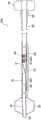
图1是本发明的第一实施方式的球囊导管的剖视图。FIG. 1 is a cross-sectional view of a balloon catheter according to a first embodiment of the present invention.
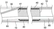
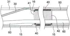
图2是表示图1所示的球囊导管的主要部分的剖视图。FIG. 2 is a cross-sectional view showing a main part of the balloon catheter shown in FIG. 1 .
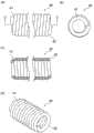
图3是表示构成图1所示的球囊导管的密卷线圈的说明图,(a)是主视图,(b)是侧视图,(c)是(a)的C-C剖视图,(d)是立体图。3 is an explanatory view showing a densely wound coil constituting the balloon catheter shown in FIG. 1 , (a) is a front view, (b) is a side view, (c) is a C-C cross-sectional view of (a), and (d) is a Stereogram.
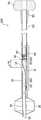
图4是本发明的第二实施方式的球囊导管的剖视图。4 is a cross-sectional view of a balloon catheter according to a second embodiment of the present invention.
图5是表示图4所示的球囊导管的主要部分的剖视图。FIG. 5 is a cross-sectional view showing a main part of the balloon catheter shown in FIG. 4 .
图6是本发明的第三实施方式的球囊导管的剖视图。6 is a cross-sectional view of a balloon catheter according to a third embodiment of the present invention.
图7是表示图6所示的球囊导管的主要部分的剖视图。FIG. 7 is a cross-sectional view showing a main part of the balloon catheter shown in FIG. 6 .
具体实施方式Detailed ways
以下,使用附图对本发明的实施方式进行详细地说明。Hereinafter, embodiments of the present invention will be described in detail with reference to the drawings.
另外,在本发明中,在说到“前端部”时意味着包括“前端”且具有一定长度的部分,在说到“后端部”时意味着包括“后端”且具有一定长度的部分。In addition, in the present invention, when referring to a "front end", it means a part including a "front end" and having a certain length, and when referring to a "rear end", it means a part including a "rear end" and having a certain length .
<第一实施方式><First Embodiment>
图1和图2所示的本实施方式的球囊导管100在经皮的冠状动脉血管成形术(PTCA)等中使用。The
该球囊导管100具备:前端侧轴10,其由树脂管构成;球囊20,其与前端侧轴10的前端连接;内管30,其是插通于前端侧轴10的管腔以及球囊20的内部而形成引线管腔的树脂管,在前端侧轴10的侧面处,其后端作为引线口而开口,其前端部固定于球囊20的前端部,其前端开口;密卷线圈40,其具有与前端侧轴10的内径大致相等的线圈外径,在被限制了朝前端方向的移动的状态下配置于前端侧轴10的管腔;后端侧轴50,其由金属管构成,其前端部插入到前端侧轴10的管腔,其前端与密卷线圈40的后端抵接,由此与前端侧轴10的后端连接;以及芯线60,其插通于前端侧轴10的管腔。The
在图1中,70是安装于后端侧轴50的后端的套部,80是变形消除件。In FIG. 1, 70 is a sleeve part attached to the rear end of the rear-
球囊导管100的前端侧轴10由树脂管构成。在前端侧轴10形成有使用于使球囊20扩张的流体流通的管腔(扩张管腔)。The distal end-
构成前端侧轴10的树脂管的外径通常为0.65~0.95mm,优选为0.70~0.90mm,若示出最佳的一个例子,则为0.83mm。The outer diameter of the resin tube constituting the distal end-
构成前端侧轴10的树脂管的内径通常为0.50~0.80mm,优选为0.55~0.75mm,若示出最佳的一个例子,则为0.71mm。The inner diameter of the resin tube constituting the distal
前端侧轴10的长度通常为200~550mm,若示出最佳的一个例子,则为345mm。The length of the distal
作为前端侧轴10(树脂管)的构成材料,能够列举出聚酰胺、聚醚聚酰胺、聚氨酯,聚醚嵌段酰胺(PEBAX)(注册商标)以及尼龙等热塑性树脂,在它们当中优选PEBAX。Examples of the constituent material of the front end side shaft 10 (resin tube) include thermoplastic resins such as polyamide, polyether polyamide, polyurethane, polyether block amide (PEBAX) (registered trademark), and nylon, and among them, PEBAX is preferable.
作为前端侧轴10(树脂管)的硬度,优选由D型硬度计测量的硬度为63~80。As the hardness of the distal end side shaft 10 (resin tube), it is preferable that the hardness measured by a D-type durometer is 63-80.
在前端侧轴10的前端安装有球囊20。A
球囊20借助在前端侧轴10和后述的后端侧轴50的管腔流通的液体而扩张。在此,能够列举出生理盐水、造影剂作为液体。The
作为扩张时的球囊20的直径,通常为0.5~4.0mm,优选为0.8~3.5mm。The diameter of the
作为球囊20的长度,通常为3~40mm,优选为6~20mm。The length of the
作为球囊20的构成材料,能够使用与构成以往公知的球囊导管的球囊相同的材料,作为最佳的材料能够列举出PEBAX。As a constituent material of the
构成球囊导管100的内管30是在前端侧轴10的管腔和球囊20的内部(内管腔)延伸,并且形成用于插通引线的管腔(引线管腔)的树脂管。The
球囊导管100是快速交换式的球囊导管,内管30的后端在前端侧轴10的侧面开口,该开口31成为引线口。另一方面,内管30的前端部固定于球囊20的前端部,在内管30的前端形成有开口32。The
构成内管30的树脂管的外径通常为0.40~0.60mm,若示出最佳的一个例子,则为0.57mm。The outer diameter of the resin tube constituting the
构成内管30的树脂管的内径通常为0.35~0.55mm,若示出最佳的一个例子,则为0.42mm。The inner diameter of the resin tube constituting the
作为从引线口亦即内管30的开口31的形成位置(开口的中心)到球囊20的后端位置为止的轴向的距离通常为150~300mm。The distance in the axial direction from the position where the
作为内管30的构成材料,能够列举出与前端侧轴10的构成材料相同的合成树脂,在它们当中优选是PEBAX。As the constituent material of the
作为内管30的硬度,优选为由D型硬度计测量的硬度为50~80。The hardness of the
在前端侧轴10的管腔配置有图3所示的密卷线圈40。构成球囊导管100的密卷线圈40由在轴向上相邻的线材彼此接触(构成线圈的线材的直径与线圈间距相等)密卷的线圈管构成。另外,该密卷线圈40相对于前端侧轴10的内周不固定(粘接)。The densely wound
密卷线圈40能够对供其配置的前端侧轴10的轴部分赋予充分的柔软性。The densely wound
另外,密卷线圈40能够容易地弯曲,但即便被作用轴向的压缩力也不会变形(压缩变形)。In addition, the densely wound
密卷线圈40的线圈外径与前端侧轴10的内径(管腔径)大致相等(实质上相同),通常为0.50~0.80mm,若示出最佳的一个例子,则为0.7mm。The coil outer diameter of the densely wound
密卷线圈40的线圈内径通常为0.40~0.60mm,若示出最佳的一个例子,则为0.5mm。The coil inner diameter of the densely wound
构成密卷线圈40的线材的直径通常为0.05~0.15mm,若示出最佳的一个例子,则为0.1mm。The diameter of the wire rod constituting the densely wound
密卷线圈40的长度通常为10~250mm(前端侧轴10的长度的1/20~1/2左右),若示出最佳的一个例子,则为106mm。The length of the densely wound
如图3所示,密卷线圈40的前端部41(前端侧的1圈)和后端部42(后端侧的1圈)的外径形成得较小(其中,前端部41和后端部42的外径大于密卷线圈40的线圈内径),构成密卷线圈40的线材的前端和后端不与前端侧轴10的内周接触。As shown in FIG. 3 , the outer diameters of the front end portion 41 (one turn on the front end side) and the rear end portion 42 (one turn on the rear end side) of the densely wound
由此,在使在管腔配置有密卷线圈40的前端侧轴10的轴部分屈曲时,能够通过线材的前端或后端防止前端侧轴10的内周面损伤。Thereby, when the shaft portion of the
如图1和图2所示,配置于前端侧轴10的管腔的密卷线圈40,其前端与内管30的后端部抵接,由此限制其朝前端方向的移动。As shown in FIGS. 1 and 2 , the densely wound
即,内管30的后端部成为限制密卷线圈朝前端方向移动的移动限制部。That is, the rear end portion of the
在前端侧轴10的后端连接有后端侧轴50。A rear
在与前端侧轴10的后端连接的后端侧轴50形成有与前端侧轴10的管腔连通的管腔(扩张管腔)。A lumen (dilation lumen) communicating with the lumen of the
该后端侧轴50由不锈钢、Ni-Ti合金、Cu-Mn-Al系合金等金属管(Hypotube)构成。The rear end-
后端侧轴50的前端部插入到前端侧轴10的后端部(管腔),后端侧轴50的前端与密卷线圈40的后端抵接,由此,后端侧轴50与前端侧轴10的后端连接。The front end portion of the rear
另外,后端侧轴50的后端部插入套部70。In addition, the rear end portion of the rear
构成后端侧轴50的金属管的外径与密卷线圈40的线圈外径大致相等,通常为0.50~0.80mm,若示出最佳的一个例子,则为0.7mm。The outer diameter of the metal tube constituting the rear-
构成后端侧轴50的金属管的内径与密卷线圈40的线圈内径大致相等,通常为0.40~0.60mm,若示出最佳的一个例子,则为0.5mm。The inner diameter of the metal pipe constituting the rear
后端侧轴50的长度通常为900~1500mm,若示出最佳的一个例子,则为1070mm。The length of the rear
插入到前端侧轴10的后端部的后端侧轴50的前端部的长度通常为5~10mm,若示出最佳的一个例子,则为8mm。The length of the front end portion of the rear
构成球囊导管100的芯线60由直线部61和锥形部62构成。芯线60将锥形部62作为前端侧插通于前端侧轴10的管腔,芯线60(直线部61)的后端侧的一部分插通于密卷线圈40的内部和后端侧轴50的管腔。The
芯线60在直线部61的后端侧处点焊于后端侧轴50的内周面,由此相对于该后端侧轴50牢固地固定。The
根据本实施方式的球囊导管100,在后端侧轴50的前端侧的前端侧轴10的管腔配置有密卷线圈40,由此在后端侧轴50的前端侧(配置有密卷线圈40的轴部分)赋予适度的柔软性,能够缓和前端侧轴10与后端侧轴50之间的急剧的刚性变化,由此能够防止将球囊导管100向血管内压入时发生扭曲。According to the
另外,构成球囊导管100的密卷线圈40,即便对它作用轴向的压缩力也不会变形(压缩变形),压入力的一部分不会被吸收而损失。In addition, the densely wound
在具备非密卷的线圈的球囊导管中,在将其向血管内压入时,在轴向上分离的线材彼此接触且该线圈被压缩,其结果压入力的一部分被吸收而损失,无法将该压入力可靠地传递到轴的前端。In a balloon catheter provided with a coil that is not densely wound, when it is pressed into a blood vessel, the wires separated in the axial direction contact each other and the coil is compressed. As a result, part of the pressing force is absorbed and lost, and it is impossible to This pressing force is reliably transmitted to the front end of the shaft.
此外,构成球囊导管100的密卷线圈40在前端侧轴10的管腔中与密卷线圈40的后端抵接,从而限制朝前端方向的移动,因此不会因密卷线圈40朝前端方向的移动而使压入力的一部分被吸收而损失。In addition, the densely wound
在不限制密卷线圈的移动的球囊导管中,在将其向血管内压入时,密卷线圈朝前端方向移动而使压入力的一部分被吸收而损失,从而无法将该压入力可靠地传递到轴的前端。In a balloon catheter that does not restrict the movement of the dense coil, when the dense coil is pushed into the blood vessel, the dense coil moves in the distal direction, and part of the pushing force is absorbed and lost, and the pushing force cannot be reliably passed to the front end of the shaft.
这样,根据本实施方式的球囊导管100,能够将来自轴(后端侧轴50)的后端的压入力可靠地传递到轴(前端侧轴10)的前端,球囊导管100能够发挥优异的推动性能。In this way, according to the
此外,密卷线圈40相对于前端侧轴10的内周不固定,并且密卷线圈40的前端相对于内管30的后端部抵接但不固定,另外,后端侧轴50的前端相对于密卷线圈40的后端抵接但不固定。因此,根据本实施方式的球囊导管100,不会有在前端侧轴10的管腔残留粘接剂等的情况,不会损害该管腔中的液体的流动性,因此不会有损害球囊20中的扩张、收缩的响应性的情况。In addition, the densely wound
<第二实施方式><Second Embodiment>
图4和图5所示的该实施方式的球囊导管200具备:由树脂管构成的前端侧轴15、球囊20、内管30、密卷线圈40、后端侧轴50以及芯线60。The
另外,在图4和图5中,用与图1和图2相同的附图标记表示的构成要素是与第一实施方式的球囊导管100相同的构成要素。In addition, in FIGS. 4 and 5 , components denoted by the same reference numerals as in FIGS. 1 and 2 are the same components as those of the
在该球囊导管200中,在前端侧轴15的内周(比内管30的开口31的形成位置靠后端侧的位置)沿着圆周方向遍布整周形成有凸部16,来作为限制密卷线圈40朝前端方向移动的移动限制部。In this
密卷线圈40的前端抵接于该凸部16,由此该密卷线圈40被限制朝前端方向的移动。When the front end of the densely wound
从引线口亦即内管30的开口31的形成位置(开口的中心)到凸部16的形成位置为止的轴向的距离(L16)优选为10mm以下。在该距离过长的情况下,在将那样的球囊导管向血管内压入时,有时会在凸部16的形成位置与开口31的形成位置之间产生扭曲而无法传递压入力。The distance ( L16 ) in the axial direction from the formation position (center of the opening) of the
另外,在本发明(权利要求5的发明)中,成为移动限制部的凸部无需遍布整周而形成,而是可以局部地形成。Moreover, in this invention (the invention of Claim 5), the convex part which becomes a movement restriction|limiting part does not need to be formed over the entire circumference, but may be formed locally.
根据本实施方式的球囊导管200,在后端侧轴50的前端侧处的前端侧轴15的管腔配置有密卷线圈40,由此能够防止将该球囊导管200向血管内压入时发生扭曲。According to the
另外,能够将来自轴(后端侧轴50)的后端的压入力可靠地传递到轴(前端侧轴15)的前端,因此球囊导管200能够发挥优异的推动性能。In addition, since the pressing force from the rear end of the shaft (rear end side shaft 50 ) can be reliably transmitted to the front end of the shaft (front end side shaft 15 ), the
<第三实施方式><Third Embodiment>
图6和图7所示的该实施方式的球囊导管300具备:由树脂管构成的前端侧轴17、球囊20、内管30、密卷线圈40、后端侧轴50以及芯线60。The
另外,在图6和图7中,用与图1和图2相同的附图标记表示的构成要素是与第一实施方式的球囊导管100相同的构成要素。In addition, in FIGS. 6 and 7 , components denoted by the same reference numerals as those in FIGS. 1 and 2 are the same components as those of the
在该球囊导管300中,前端侧轴17具有小径部18作为限制密卷线圈40朝前端方向移动的移动限制部,该小径部18具有比密卷线圈40的线圈外径小的内径。In this
密卷线圈40的前端抵接于在前端侧轴15的小径部18的后端形成的阶梯差,由此限制该密卷线圈40朝前端方向的移动。The front end of the densely wound
根据本实施方式的球囊导管300,在后端侧轴50的前端侧的前端侧轴17的管腔配置有密卷线圈40,由此能够防止在将该球囊导管300向血管内压入时发生扭曲。According to the
另外,能够将来自轴(后端侧轴50)的后端的压入力可靠地传递到轴(前端侧轴17)的前端,从而球囊导管300能够发挥优异的推动性能。In addition, the pressing force from the rear end of the shaft (rear end side shaft 50 ) can be reliably transmitted to the front end of the shaft (front end side shaft 17 ), so that the
以上,对本发明的实施方式进行了说明,但本发明并不限定于上述内容,而是能够进行各种变更。As mentioned above, although embodiment of this invention was described, this invention is not limited to the content mentioned above, Various changes are possible.
例如,在第三实施方式中,至前端侧轴17的前端为止为小径部18,但比开口31的形成位置靠前端侧的位置也可以不是小径部。For example, in the third embodiment, the
附图标记说明Description of reference numerals
100…球囊导管;10…前端侧轴;20…球囊;30…内管;31…开口(引线口);32…开口;40…密卷线圈;41…密卷线圈的前端部;42…密卷线圈的后端部;50…后端侧轴;60…芯线;61…直线部;62…锥形部;70…套部;80…变形消除件;200…球囊导管;15…前端侧轴;16…凸部(移动限制部);300…球囊导管;17…前端侧轴;18…前端侧轴的小径部(移动限制部)。100...balloon catheter; 10...front end side shaft; 20...balloon; 30...inner tube; 31...opening (lead port); 32...opening; ...rear end portion of densely wound coil; 50...rear end side shaft; 60...core wire; 61...straight portion; 62...tapered portion; 70...sleeve portion; ... distal end shaft; 16 ... convex portion (movement restricting portion); 300... balloon catheter; 17... distal end shaft; 18... small diameter portion (moving restricting portion) of the distal end shaft.
Claims (7)
Applications Claiming Priority (1)
| Application Number | Priority Date | Filing Date | Title |
|---|---|---|---|
| PCT/JP2018/021314WO2019234784A1 (en) | 2018-06-04 | 2018-06-04 | Balloon catheter |
Publications (1)
| Publication Number | Publication Date |
|---|---|
| CN111971085Atrue CN111971085A (en) | 2020-11-20 |
Family
ID=68770950
Family Applications (1)
| Application Number | Title | Priority Date | Filing Date |
|---|---|---|---|
| CN201880092385.5APendingCN111971085A (en) | 2018-06-04 | 2018-06-04 | Balloon catheter |
Country Status (4)
| Country | Link |
|---|---|
| JP (1) | JP6906883B2 (en) |
| KR (1) | KR20210003249A (en) |
| CN (1) | CN111971085A (en) |
| WO (1) | WO2019234784A1 (en) |
Families Citing this family (1)
| Publication number | Priority date | Publication date | Assignee | Title |
|---|---|---|---|---|
| WO2024070305A1 (en) | 2022-09-29 | 2024-04-04 | テルモ株式会社 | Balloon catheter |
Citations (11)
| Publication number | Priority date | Publication date | Assignee | Title |
|---|---|---|---|---|
| US4748982A (en)* | 1987-01-06 | 1988-06-07 | Advanced Cardiovascular Systems, Inc. | Reinforced balloon dilatation catheter with slitted exchange sleeve and method |
| US5217482A (en)* | 1990-08-28 | 1993-06-08 | Scimed Life Systems, Inc. | Balloon catheter with distal guide wire lumen |
| US5507766A (en)* | 1993-01-26 | 1996-04-16 | Terumo Kabushiki Kaisha | Vascular dilatation instrument and catheter |
| US5531719A (en)* | 1993-06-29 | 1996-07-02 | Terumo Kabushiki Kaisha | Vascular catheter with helical space |
| US5545134A (en)* | 1994-04-15 | 1996-08-13 | Laboratoire Nycomed Sa | Rapid-exchange dilatation catheter |
| JP2001149482A (en)* | 1999-11-26 | 2001-06-05 | Terumo Corp | Catheter |
| JP2005270466A (en)* | 2004-03-25 | 2005-10-06 | Terumo Corp | Guide wire |
| US20120004606A1 (en)* | 2009-03-06 | 2012-01-05 | Cook Medical Technologies Llc | Reinforced rapid exchange catheter |
| JP2012152353A (en)* | 2011-01-25 | 2012-08-16 | Asahi Intecc Co Ltd | Balloon catheter |
| JP2017012522A (en)* | 2015-07-02 | 2017-01-19 | 朝日インテック株式会社 | Balloon catheter |
| CN107073244A (en)* | 2014-10-20 | 2017-08-18 | 美敦力 | Centralized positioning coil form guiding piece |
- 2018
- 2018-06-04JPJP2020523849Apatent/JP6906883B2/enactiveActive
- 2018-06-04WOPCT/JP2018/021314patent/WO2019234784A1/ennot_activeCeased
- 2018-06-04CNCN201880092385.5Apatent/CN111971085A/enactivePending
- 2018-06-04KRKR1020207034533Apatent/KR20210003249A/ennot_activeCeased
Patent Citations (11)
| Publication number | Priority date | Publication date | Assignee | Title |
|---|---|---|---|---|
| US4748982A (en)* | 1987-01-06 | 1988-06-07 | Advanced Cardiovascular Systems, Inc. | Reinforced balloon dilatation catheter with slitted exchange sleeve and method |
| US5217482A (en)* | 1990-08-28 | 1993-06-08 | Scimed Life Systems, Inc. | Balloon catheter with distal guide wire lumen |
| US5507766A (en)* | 1993-01-26 | 1996-04-16 | Terumo Kabushiki Kaisha | Vascular dilatation instrument and catheter |
| US5531719A (en)* | 1993-06-29 | 1996-07-02 | Terumo Kabushiki Kaisha | Vascular catheter with helical space |
| US5545134A (en)* | 1994-04-15 | 1996-08-13 | Laboratoire Nycomed Sa | Rapid-exchange dilatation catheter |
| JP2001149482A (en)* | 1999-11-26 | 2001-06-05 | Terumo Corp | Catheter |
| JP2005270466A (en)* | 2004-03-25 | 2005-10-06 | Terumo Corp | Guide wire |
| US20120004606A1 (en)* | 2009-03-06 | 2012-01-05 | Cook Medical Technologies Llc | Reinforced rapid exchange catheter |
| JP2012152353A (en)* | 2011-01-25 | 2012-08-16 | Asahi Intecc Co Ltd | Balloon catheter |
| CN107073244A (en)* | 2014-10-20 | 2017-08-18 | 美敦力 | Centralized positioning coil form guiding piece |
| JP2017012522A (en)* | 2015-07-02 | 2017-01-19 | 朝日インテック株式会社 | Balloon catheter |
Non-Patent Citations (1)
| Title |
|---|
| 曹亚军: "《数控车床操作与编程疑难问答》", 30 April 2012* |
Also Published As
| Publication number | Publication date |
|---|---|
| JP6906883B2 (en) | 2021-07-21 |
| JPWO2019234784A1 (en) | 2020-12-17 |
| WO2019234784A1 (en) | 2019-12-12 |
| KR20210003249A (en) | 2021-01-11 |
Similar Documents
| Publication | Publication Date | Title |
|---|---|---|
| JP4583718B2 (en) | Guide wire with flexible tip | |
| US8043232B2 (en) | High performance wire guide | |
| US7481778B2 (en) | Guidewire with deflectable tip having improved flexibility | |
| CN105473177B (en) | balloon catheter | |
| JP4667822B2 (en) | Operable balloon catheter | |
| JP5023067B2 (en) | Connecting wire guide | |
| CA2228346C (en) | Guidewire having a distal tip that can change its shape within a vessel | |
| US6039699A (en) | Stiff catheter guidewire with flexible distal portion | |
| JP5142230B2 (en) | Guide wire | |
| JPH10511586A (en) | Intravascular guidewire and method | |
| JP2002514474A (en) | High performance coil wire | |
| CN107073247B (en) | Balloon catheter | |
| JP2005125100A (en) | Guide wire having flexible tip part improved in torque characteristic | |
| US20210322730A1 (en) | Guidewire having bonded proximal and distal segments | |
| CN106075701B (en) | balloon catheter | |
| JP7671291B2 (en) | Guidewires for medical devices | |
| JP2001333984A (en) | Balloon catheter | |
| CN111971085A (en) | Balloon catheter | |
| JP2006271901A (en) | Coiled contrast marker, method for manufacturing the same, and catheter | |
| CN111163832B (en) | Guide wire | |
| JP6304886B2 (en) | Balloon catheter | |
| CN111601632A (en) | Catheter tube | |
| EP0911055A1 (en) | Guidewire with outer sheath | |
| JP6399809B2 (en) | Medical guidewire | |
| WO2016190009A1 (en) | Balloon catheter |
Legal Events
| Date | Code | Title | Description |
|---|---|---|---|
| PB01 | Publication | ||
| PB01 | Publication | ||
| SE01 | Entry into force of request for substantive examination | ||
| SE01 | Entry into force of request for substantive examination | ||
| RJ01 | Rejection of invention patent application after publication | Application publication date:20201120 | |
| RJ01 | Rejection of invention patent application after publication |