CN111971084B - Releasable safety catheter insertion assembly - Google Patents
Releasable safety catheter insertion assemblyDownload PDFInfo
- Publication number
- CN111971084B CN111971084BCN201980023690.3ACN201980023690ACN111971084BCN 111971084 BCN111971084 BCN 111971084BCN 201980023690 ACN201980023690 ACN 201980023690ACN 111971084 BCN111971084 BCN 111971084B
- Authority
- CN
- China
- Prior art keywords
- needle
- safety clip
- control valve
- safety
- blood control
- Prior art date
- Legal status (The legal status is an assumption and is not a legal conclusion. Google has not performed a legal analysis and makes no representation as to the accuracy of the status listed.)
- Active
Links
Images


Classifications
- A—HUMAN NECESSITIES
- A61—MEDICAL OR VETERINARY SCIENCE; HYGIENE
- A61M—DEVICES FOR INTRODUCING MEDIA INTO, OR ONTO, THE BODY; DEVICES FOR TRANSDUCING BODY MEDIA OR FOR TAKING MEDIA FROM THE BODY; DEVICES FOR PRODUCING OR ENDING SLEEP OR STUPOR
- A61M25/00—Catheters; Hollow probes
- A61M25/01—Introducing, guiding, advancing, emplacing or holding catheters
- A61M25/06—Body-piercing guide needles or the like
- A61M25/0612—Devices for protecting the needle; Devices to help insertion of the needle, e.g. wings or holders
- A61M25/0618—Devices for protecting the needle; Devices to help insertion of the needle, e.g. wings or holders having means for protecting only the distal tip of the needle, e.g. a needle guard
- A—HUMAN NECESSITIES
- A61—MEDICAL OR VETERINARY SCIENCE; HYGIENE
- A61M—DEVICES FOR INTRODUCING MEDIA INTO, OR ONTO, THE BODY; DEVICES FOR TRANSDUCING BODY MEDIA OR FOR TAKING MEDIA FROM THE BODY; DEVICES FOR PRODUCING OR ENDING SLEEP OR STUPOR
- A61M25/00—Catheters; Hollow probes
- A61M25/0097—Catheters; Hollow probes characterised by the hub
- A—HUMAN NECESSITIES
- A61—MEDICAL OR VETERINARY SCIENCE; HYGIENE
- A61M—DEVICES FOR INTRODUCING MEDIA INTO, OR ONTO, THE BODY; DEVICES FOR TRANSDUCING BODY MEDIA OR FOR TAKING MEDIA FROM THE BODY; DEVICES FOR PRODUCING OR ENDING SLEEP OR STUPOR
- A61M25/00—Catheters; Hollow probes
- A61M25/01—Introducing, guiding, advancing, emplacing or holding catheters
- A61M25/06—Body-piercing guide needles or the like
- A61M25/0606—"Over-the-needle" catheter assemblies, e.g. I.V. catheters
- A—HUMAN NECESSITIES
- A61—MEDICAL OR VETERINARY SCIENCE; HYGIENE
- A61M—DEVICES FOR INTRODUCING MEDIA INTO, OR ONTO, THE BODY; DEVICES FOR TRANSDUCING BODY MEDIA OR FOR TAKING MEDIA FROM THE BODY; DEVICES FOR PRODUCING OR ENDING SLEEP OR STUPOR
- A61M25/00—Catheters; Hollow probes
- A61M25/01—Introducing, guiding, advancing, emplacing or holding catheters
- A61M25/06—Body-piercing guide needles or the like
- A61M25/0612—Devices for protecting the needle; Devices to help insertion of the needle, e.g. wings or holders
- A—HUMAN NECESSITIES
- A61—MEDICAL OR VETERINARY SCIENCE; HYGIENE
- A61M—DEVICES FOR INTRODUCING MEDIA INTO, OR ONTO, THE BODY; DEVICES FOR TRANSDUCING BODY MEDIA OR FOR TAKING MEDIA FROM THE BODY; DEVICES FOR PRODUCING OR ENDING SLEEP OR STUPOR
- A61M25/00—Catheters; Hollow probes
- A61M25/01—Introducing, guiding, advancing, emplacing or holding catheters
- A61M25/06—Body-piercing guide needles or the like
- A61M25/0662—Guide tubes
- A—HUMAN NECESSITIES
- A61—MEDICAL OR VETERINARY SCIENCE; HYGIENE
- A61M—DEVICES FOR INTRODUCING MEDIA INTO, OR ONTO, THE BODY; DEVICES FOR TRANSDUCING BODY MEDIA OR FOR TAKING MEDIA FROM THE BODY; DEVICES FOR PRODUCING OR ENDING SLEEP OR STUPOR
- A61M39/00—Tubes, tube connectors, tube couplings, valves, access sites or the like, specially adapted for medical use
- A61M39/22—Valves or arrangement of valves
- A—HUMAN NECESSITIES
- A61—MEDICAL OR VETERINARY SCIENCE; HYGIENE
- A61M—DEVICES FOR INTRODUCING MEDIA INTO, OR ONTO, THE BODY; DEVICES FOR TRANSDUCING BODY MEDIA OR FOR TAKING MEDIA FROM THE BODY; DEVICES FOR PRODUCING OR ENDING SLEEP OR STUPOR
- A61M5/00—Devices for bringing media into the body in a subcutaneous, intra-vascular or intramuscular way; Accessories therefor, e.g. filling or cleaning devices, arm-rests
- A61M5/14—Infusion devices, e.g. infusing by gravity; Blood infusion; Accessories therefor
- A61M5/158—Needles for infusions; Accessories therefor, e.g. for inserting infusion needles, or for holding them on the body
- A61M2005/1585—Needle inserters
- A—HUMAN NECESSITIES
- A61—MEDICAL OR VETERINARY SCIENCE; HYGIENE
- A61M—DEVICES FOR INTRODUCING MEDIA INTO, OR ONTO, THE BODY; DEVICES FOR TRANSDUCING BODY MEDIA OR FOR TAKING MEDIA FROM THE BODY; DEVICES FOR PRODUCING OR ENDING SLEEP OR STUPOR
- A61M5/00—Devices for bringing media into the body in a subcutaneous, intra-vascular or intramuscular way; Accessories therefor, e.g. filling or cleaning devices, arm-rests
- A61M5/14—Infusion devices, e.g. infusing by gravity; Blood infusion; Accessories therefor
- A61M5/158—Needles for infusions; Accessories therefor, e.g. for inserting infusion needles, or for holding them on the body
- A61M2005/1587—Needles for infusions; Accessories therefor, e.g. for inserting infusion needles, or for holding them on the body suitable for being connected to an infusion line after insertion into a patient
Landscapes
- Health & Medical Sciences (AREA)
- Life Sciences & Earth Sciences (AREA)
- Heart & Thoracic Surgery (AREA)
- Animal Behavior & Ethology (AREA)
- Anesthesiology (AREA)
- Biomedical Technology (AREA)
- Hematology (AREA)
- Engineering & Computer Science (AREA)
- General Health & Medical Sciences (AREA)
- Public Health (AREA)
- Veterinary Medicine (AREA)
- Pulmonology (AREA)
- Biophysics (AREA)
- Vascular Medicine (AREA)
- Infusion, Injection, And Reservoir Apparatuses (AREA)
- Media Introduction/Drainage Providing Device (AREA)
Abstract
Description
Translated fromChinese相关申请信息Related application information
本申请要求美国临时申请号62/624,470(2018年1月31日提交)和美国临时申请号62/643,229(2018年3月15日提交)的权益,其全部内容通过引用全部并入本文。This application claims the benefit of U.S. Provisional Application No. 62/624,470 (filed January 31, 2018) and U.S. Provisional Application No. 62/643,229 (filed March 15, 2018), the entire contents of which are hereby incorporated by reference in their entirety.
技术领域technical field
本公开总体上涉及安全导管,并且更特别地涉及一种具有被动释放机构的安全导管,该被动释放机构配置成在从导管插入装置释放导管接口之前遮蔽针头套管的尖锐的远侧尖端。The present disclosure relates generally to safety catheters, and more particularly to a safety catheter having a passive release mechanism configured to shield a sharpened distal tip of a needle cannula prior to releasing a catheter hub from a catheter insertion device.
背景技术Background technique
静脉内(IV)治疗是一种用于对患者施用医疗流体和从患者抽出体液的通用技术。IV治疗已被用于各种目的,诸如维持血液和电解质平衡、输血、施用营养补充剂、化学治疗以及施用麻醉剂和药物。这些流体(在本文中统称为药物)可以通过皮下针头、在静脉内通过注入施用,或者使用针头或者导管通过输注间歇地或者连续地施用。临床医生使用的一种常见的静脉内通路装置是外周静脉导管(PIVC)。Intravenous (IV) therapy is a common technique for administering medical fluids to and withdrawing bodily fluids from patients. IV therapy has been used for various purposes, such as maintaining blood and electrolyte balance, blood transfusions, administering nutritional supplements, chemotherapy, and administering anesthetics and drugs. These fluids (collectively referred to herein as drugs) may be administered through a hypodermic needle, intravenously by infusion, or intermittently or continuously by infusion using a needle or catheter. One common intravenous access device used by clinicians is the peripheral venous catheter (PIVC).
PIVC由柔软的柔性塑料或者硅胶制成,大小通常为14到24号。在常规的静脉穿刺过程中,将导管插入患者的手、脚或者手臂内侧的静脉中,或者将接受IV导管的身体中的任何静脉中。为了将IV导管放置到患者的静脉中,使用尖锐的导引针头穿刺皮肤、组织和静脉壁,以提供用于将导管放置到静脉中的路径。PIVCs are made of soft, flexible plastic or silicone and usually come in sizes 14 to 24. During a conventional venipuncture procedure, a catheter is inserted into a vein in a patient's hand, foot, or inside arm, or any vein in the body that will receive an IV catheter. To place an IV catheter into a patient's vein, a sharp guide needle is used to puncture the skin, tissue, and wall of the vein to provide a path for placing the catheter into the vein.
参考图1A-B,描绘了常规的导管插入组件50,其包括配置成插入“针头上(overthe needle)”导管54的导管插入装置52。导管54总体上包括导管管部56,导管管部56具有用于插入生物部位的远端58、近端60和限定在其间延伸的管腔体的柔性壁。通常,导管管部56的近端60可操作地耦接到导管接口62。部分地通过将导管54同轴地定位在导管插入装置52的针头套管64上,导管54能够可操作地耦接到导管插入装置52。导管54因此与针头套管64一起穿过皮肤、组织和静脉壁进入患者的静脉中。Referring to FIGS. 1A-B , a
已经开发出各种导管插入装置以提供用于导管插入的针头。这种导管插入装置的一个这种示例由明尼苏达州圣保罗的Smiths Medical ASD公司以JELCO和INTUITIV商标出售并且在美国专利号8,257,322和美国专利公开号2011/0319838和2017/0095617中描述,其内容通过引用并入本文。在其他情况下,导管插入装置提供安全针头组件,该安全针头组件的功能是容纳针头的尖锐的尖端以减少无意的针头刺伤的可能性。这种类型的导管插入装置的示例由Smiths Medical ASD公司以PROTECTIV和VIAVALVE商标出售并且在美国专利号5,000,740、7,736,342和美国专利公开号2016/0220791中描述,其内容通过引用并入本文。Various catheterization devices have been developed to provide a needle for catheterization. One such example of such a catheterization device is sold under the JELCO and INTUITIV trademarks by Smiths Medical ASD Company of St. Paul, MN and is described in U.S. Patent No. 8,257,322 and U.S. Patent Publication Nos. 2011/0319838 and 2017/0095617, the contents of which are incorporated by reference Incorporated into this article. In other cases, the catheterization device provides a safety needle assembly that functions to accommodate the sharp point of the needle to reduce the possibility of inadvertent needle stick injuries. Examples of catheterization devices of this type are sold under the PROTECTIV and VIAVALVE trademarks by Smiths Medical ASD and are described in US Patent Nos. 5,000,740, 7,736,342 and US Patent Publication No. 2016/0220791, the contents of which are incorporated herein by reference.
一旦导管管部56已经进入患者的静脉中,就使针头套管64和导管54朝向患者的皮肤降低以减小进入角,并且导管管部56略微前进入静脉中。然后松开导管54和针头套管64之间的连接,使得能够根据需要使导管管部56进一步前进到静脉中,并且能够将针头套管64从导管54抽出。Once
在一些情况下,导管54能够包括尖端保护器,针头套管64的至少一部分穿过该尖端保护器。尖端保护器能够配置成在已经将针头套管64的尖锐的远侧尖端66从导管管部56抽出,后将该尖锐的远侧尖端66包围或者以其他方式遮蔽。尖端保护器的一种形式涉及配合在导管接口62内的夹子。这种夹子能够包括金属等的薄的腹板,该腹板是弯曲的或者以其他方式形成为具有后壁和一个或多个向远侧延伸的壁,这些壁通常都具有相同的厚度。在夹子的准备状态下,针头套管64的轴穿过夹子的后壁中的孔口并且抵靠一对向远侧延伸的臂,以进入导管管部56。能够相对于夹子向近侧拉动针头套管62,以便将远侧尖端66带到后壁的近侧的、夹子内,于是臂被配置成闭合以阻挡远侧尖端66的向远侧再出现。针头套管64的进一步的向近侧移动将尖端保护器拉出导管接口62。In some cases,
导管接口62能够耦接到施加组或者注射器,以用于将流体引入患者和/或从患者抽出体液。导管接口62能够具有开口的近端68,该近端适于将公鲁尔(luer)锥接收到腔体中,该腔体中限定为在患者的脉管系统与鲁尔锥之间形成流体连接。近端68还能够提供有外部耳70等,以将鲁尔锥固定在导管接口62中,诸如当鲁尔锥与施加组或者注射器的公鲁尔锁环耦接时。
在正常情况下,在抽出针头套管64之后以及在将鲁尔锥插入到导管接口62中之前,血液流过导管管部54并且进入导管接口62的内部腔体。为了限制血液流动,导管接口62能够包括阀或者隔膜,该阀或者隔膜在已经从导管54抽出针头套管64之后密封针头套管路径,从而阻止来自患者的血液或者体液从导管54逸出到周围环境。Under normal circumstances, blood flows through the
已经创建了在插入期间试图将导管54锁定到导管插入装置52的导管插入装置50。然而,能够改进这样的装置以始终如一地使得能够从针头套管64平稳地释放导管接口62,特别是以减少或者消除无意的针头刺伤的风险的方式。因此,本公开的申请人已经认同了对安全导管插入组件的需求,该安全导管插入组件包括在缩回针头套管时从导管插入装置平稳且被动地释放导管的机构。
发明内容Contents of the invention
本公开的实施例提供了一种安全导管插入组件,该安全导管插入组件包括用于在将针头套管抽出到尖端保护器中时从导管插入装置平稳地且被动地释放导管的机构,从而在改进导管插入过程的同时抑制了无意的针头刺伤的风险。Embodiments of the present disclosure provide a safety catheterization assembly that includes a mechanism for smoothly and passively releasing the catheter from the catheterization device as the needle cannula is withdrawn into the tip protector, thereby Improves the catheterization process while reducing the risk of inadvertent needle stick injuries.
本公开的一个实施例提供了一种安全导管插入组件,其包括导管组件、导管插入装置和被动释放机构。导管组件包括导管接口和其向远侧延伸的导管管部。导管接口能够具有开口的近端和远端,并在其间限定内部腔体。导管插入装置能够包括针头接口和从针头接口向远侧延伸的针头套管。针头套管能够具有尖锐的远侧尖端。被动释放机构能够被配置成将导管接口耦接到导管插入装置,并且能够包括顺应性密封构件和安全夹。顺应性密封构件能够布置在导管接口的内部腔体中,并且能够具有开放的远端和近端,并在其间限定内部腔体。安全夹能够可释放地耦接到顺应性密封构件,并且能够配置成相对于针头套管在第一位置与第二位置之间移动,在第一位置处,远侧尖端从安全夹向远侧延伸,在第二位置处,远侧尖端被捕获在安全夹内。在第一位置处,安全夹的一部分对顺应性密封构件的一部分施加压缩力。在第二位置处,实现减小的压缩力和从顺应性密封构件释放安全夹,使得在从顺应性密封构件释放针头夹之前,阻止接近针头套管的远侧尖端。One embodiment of the present disclosure provides a safety catheterization assembly that includes a catheter assembly, a catheterization device, and a passive release mechanism. The catheter assembly includes a catheter hub and a distally extending catheter tube thereof. The catheter hub can have open proximal and distal ends and define an interior lumen therebetween. The catheter insertion device can include a needle hub and a needle cannula extending distally from the needle hub. The needle cannula can have a sharpened distal tip. The passive release mechanism can be configured to couple the catheter interface to the catheter insertion device and can include a compliant sealing member and a safety clip. A compliant sealing member can be disposed within the interior cavity of the catheter hub and can have open distal and proximal ends defining an interior cavity therebetween. The safety clip is releasably coupled to the compliant sealing member and is configured to move relative to the needle cannula between a first position and a second position in which the distal tip is distal from the safety clip Extended, in the second position, the distal tip is captured within the safety clip. In the first position, a portion of the safety clip exerts a compressive force on a portion of the compliant seal member. In the second position, a reduced compressive force is achieved and the safety clip is released from the compliant sealing member such that access to the distal tip of the needle cannula is prevented until the needle clip is released from the compliant sealing member.
在一个实施例中,当安全夹处于第二位置时,能够在没有实质性的干扰的情况下,从导管接口移除针头插入组件。在一个实施例中,顺应性密封构件是血液控制阀。在一个实施例中,安全导管插入组件还包括在导管接口的内部腔体中向近侧延伸的刚性致动器,该刚性致动器的自由近端包括扩大的近侧凸缘。在一个实施例中,顺应性密封构件能够包括配置成容纳刚性致动器的扩大的近侧凸缘的致动器腔体,以及限定在致动器腔体近侧的阀狭缝的膜,其中刚性致动器的近侧凸缘相对于顺应性密封构件能在第一位置与第二位置之间移位,在第一位置处,阀狭缝闭合,在第二位置处,阀狭缝打开。在一个实施例中,安全导管插入组件还包括可操作地耦接到顺应性密封构件的近侧杯状体,该近侧杯状体具有开放的远端和近端,并在其间限定腔体,由顺应性密封构件限定的腔体与由近侧杯状体限定的腔体邻接,以形成配置成容纳安全夹的腔体。在一个实施例中,近侧杯状体还包括杆延伸部,该杆延伸部配置成与针头套管的外径符合,以便阻止体液从近侧杯状体的腔体内通过。在一个实施例中,顺应性密封构件包括:血液控制阀以及擦拭器组件,该血液控制阀配置成使针头套管能够选择性地穿过其中,该擦拭器组件定位在血液控制阀的远侧并且配置成阻止体液穿过其中。在一个实施例中,安全夹包括第一臂和第二臂,第一臂和第二臂朝向位于其间的针头套管的纵向轴线偏置。在一个实施例中,第一臂包括第一针头套管引导表面,且第二臂包括第二针头套管引导表面,使得当安全夹处于第二位置时,第一针头套管引导表面和第二针头套管引导表面延伸超过针头套管的纵向轴线。在一个实施例中,第一臂包括一对针头套管引导表面,当使安全夹移动到第二位置时,该一对针头套管引导表面延伸超过针头套管的纵向轴线。In one embodiment, the needle insertion assembly can be removed from the catheter hub without substantial disturbance when the safety clip is in the second position. In one embodiment, the compliant sealing member is a blood control valve. In one embodiment, the safety catheterization assembly further includes a rigid actuator extending proximally within the interior cavity of the catheter hub, the free proximal end of the rigid actuator including an enlarged proximal flange. In one embodiment, the compliant sealing member can include an actuator cavity configured to receive an enlarged proximal flange of the rigid actuator, and a membrane defining a valve slit proximal to the actuator cavity, Wherein the proximal flange of the rigid actuator is displaceable relative to the compliant sealing member between a first position in which the valve slit is closed and a second position in which the valve slit is closed. Open. In one embodiment, the safety catheterization assembly further includes a proximal cup operably coupled to the compliant sealing member, the proximal cup having open distal and proximal ends and defining a cavity therebetween , the cavity defined by the compliant sealing member adjoins the cavity defined by the proximal cup to form a cavity configured to receive the safety clip. In one embodiment, the proximal cup further includes a stem extension configured to conform to the outer diameter of the needle cannula to prevent passage of bodily fluids from within the lumen of the proximal cup. In one embodiment, the compliant sealing member includes a blood control valve configured to enable selective passage of a needle cannula therethrough, and a wiper assembly positioned distal to the blood control valve And configured to prevent passage of bodily fluids therethrough. In one embodiment, the safety clip includes a first arm and a second arm that are biased toward the longitudinal axis of the needle cannula located therebetween. In one embodiment, the first arm comprises a first needle cannula guiding surface and the second arm comprises a second needle cannula guiding surface such that when the safety clip is in the second position, the first needle cannula guiding surface and the second needle cannula guiding surface Two needle cannula guiding surfaces extend beyond the longitudinal axis of the needle cannula. In one embodiment, the first arm includes a pair of needle cannula guiding surfaces that extend beyond the longitudinal axis of the needle cannula when the safety clip is moved to the second position.
本公开的另一个实施例提供了一种被动安全导管组件。该被动安全导管组件能够包括导管组件、导管插入装置和被动释放机构。导管组件能够包括导管接口和其向远侧延伸的导管管部。导管插入装置能够包括针头接口和其向远侧延伸的针头套管。针头套管能够包括尖锐的远侧尖端。被动释放机构能够包括接收在导管接口内的顺应性外部密封构件,以及至少部分地接收在顺应性外部密封构件内的内部针头夹构件。针头套管能够滑动地接收在内部夹构件内,并且能够在第一位置与第二位置之间移动,在第一位置处,针头套管迫使内部针头夹构件的一部分与顺应性外部密封构件压缩接触,在第二位置处,远侧尖端被捕获在内部针头夹构件内并且减小压缩接触,使得能够在没有实质性干扰的情况下,从导管接口移除插入针头组件。Another embodiment of the present disclosure provides a passive safety catheter assembly. The passive safety catheter assembly can include a catheter assembly, a catheter insertion device, and a passive release mechanism. The catheter assembly can include a catheter hub and a distally extending catheter tube thereof. The catheter insertion device can include a needle hub and a distally extending needle cannula therefor. The needle cannula can include a sharpened distal tip. The passive release mechanism can include a compliant outer sealing member received within the catheter hub, and an inner needle grip member at least partially received within the compliant outer sealing member. The needle cannula is slidably received within the inner needle grip member and is movable between a first position and a second position in which the needle cannula forces a portion of the inner needle grip member into compression with the compliant outer sealing member Contact, in the second position, the distal tip is captured within the inner needle grip member and the compression contact is reduced, enabling removal of the inserted needle assembly from the catheter hub without substantial interference.
在一个实施例中,内部针头夹构件配置成在从顺应性外部密封构件释放针头夹之前捕获针头套管的远侧尖端。在一个实施例中,顺应性外部密封构件能够在第一位置与第二位置之间移位,在第一位置处,顺应性外部密封构件的血液控制阀闭合,在第二位置处,血液控制阀打开。在一个实施例中,被动安全导管组件还包括可操作地耦接到顺应性外部密封构件的近侧杯状体,该近侧杯状体具有开放的远端和近端,并在其间限定腔体,由顺应性外部密封构件限定的该腔体与由所述近侧杯状体限定的腔体邻接,以形成配置成容纳所述内部针头夹构件的腔体。在一个实施例中,顺应性外部密封构件能够包括:膜和擦拭器组件,该膜限定了血液控制阀,该血液控制阀配置成使针头套管能够选择性地穿过其中,该擦拭器组件定位在血液控制阀的远侧并配置成阻止体液穿过其中。In one embodiment, the inner needle clamp member is configured to capture the distal tip of the needle cannula prior to release of the needle clamp from the compliant outer sealing member. In one embodiment, the compliant outer sealing member is displaceable between a first position in which the blood control valve of the compliant outer sealing member is closed and a second position in which the blood control valve is closed. The valve opens. In one embodiment, the passive safety catheter assembly further includes a proximal cup operatively coupled to the compliant outer sealing member, the proximal cup having open distal and proximal ends and defining a lumen therebetween The cavity defined by the compliant outer sealing member adjoins the cavity defined by the proximal cup to form a cavity configured to receive the inner needle clamp member. In one embodiment, the compliant outer sealing member can include a membrane defining a blood control valve configured to selectively enable a needle cannula to pass therethrough, and a wiper assembly Positioned distal to the blood control valve and configured to prevent bodily fluid from passing therethrough.
本公开的另一个实施例提供了一种导管接口组件。该导管接口组件能够包括导管接口主体、刚性致动器、顺应性密封构件和安全夹。导管接口主体能够具有开口的近端和远端,并在其间限定内部腔体。刚性致动器能够在导管接口的内部腔体中、从导管接口远端向近侧延伸至自由端。致动器能够在其自由端具有扩大的近侧凸缘。顺应性密封构件能够布置在导管接口的内部腔体中。顺应性密封构件能够包括配置成容纳刚性致动器的扩大的近侧凸缘的致动器腔体,以及限定在致动器腔体近侧的阀孔口位置的膜,其中刚性致动器的近侧凸缘能够相对于顺应性密封构件在第一位置与第二位置之间移位,在第一位置处,阀孔口被偏置闭合,在第二位置处,阀孔口被偏置打开。安全夹能够部分地容纳在顺应性密封构件内。安全夹能够被配置成在第一位置与第二位置之间移动,在第一位置处,安全夹的一部分使顺应性密封构件的一部分向外偏置成干扰与导管接口的内部腔体的内径的接触,在第二位置处,消除了安全夹对顺应性密封构件的向外偏置。Another embodiment of the present disclosure provides a catheter interface assembly. The catheter interface assembly can include a catheter interface body, a rigid actuator, a compliant sealing member, and a safety clip. The catheter interface body can have open proximal and distal ends and define an interior cavity therebetween. A rigid actuator can extend proximally from the catheter hub distal end to a free end within the interior lumen of the catheter hub. The actuator can have an enlarged proximal flange at its free end. A compliant sealing member can be disposed within the interior cavity of the catheter interface. The compliant sealing member can include an actuator cavity configured to receive an enlarged proximal flange of the rigid actuator, and a membrane defining a valve orifice location proximal to the actuator cavity, wherein the rigid actuator The proximal flange of the compliant seal member is displaceable between a first position in which the valve orifice is biased closed and a second position in which the valve orifice is biased closed. set to open. The safety clip is partially houseable within the compliant seal member. The safety clip is configurable to move between a first position and a second position in which a portion of the safety clip biases a portion of the compliant sealing member outwardly to interfere with the inner diameter of the inner cavity interfacing with the catheter The contact, in the second position, eliminates the outward bias of the safety clip against the compliant seal member.
本公开的另一个实施例提供了一种导管接口组件。导管接口组件能够包括导管接口主体、顺应性密封构件、近侧杯状体和安全夹。导管接口主体能够具有开口的近端和远端,并在其间限定内部腔体。顺应性密封构件能够布置在导管接口的内部腔体中。顺应性密封构件能够具有开放的远端和近端,并在其间限定腔体。近侧杯状体能够可操作地耦接到顺应性密封构件。近侧杯状体能够具有开放的远端和近端,并在其间限定腔体。由顺应性构件限定的腔体能够与由近侧杯状体限定的腔体邻接以形成安全夹腔体。安全夹能够容纳在安全夹腔体内。安全夹能够配置成在第一位置与第二位置之间移动,在第一位置处,该安全夹的一部分使顺应性密封构件的一部分向外偏置成干扰与导管接口的内部腔体的内径的接触,在第二位置处,消除了安全夹对顺应性密封构件的向外偏置。Another embodiment of the present disclosure provides a catheter interface assembly. The catheter interface assembly can include a catheter interface body, a compliant seal member, a proximal cup, and a safety clip. The catheter interface body can have open proximal and distal ends and define an interior cavity therebetween. A compliant sealing member can be disposed within the interior cavity of the catheter interface. The compliant sealing member can have open distal and proximal ends and define a cavity therebetween. The proximal cup can be operably coupled to the compliant seal member. The proximal cup can have open distal and proximal ends and define a cavity therebetween. The cavity defined by the compliant member is contiguous with the cavity defined by the proximal cup to form a safety clip cavity. The safety clip can be accommodated in the safety clip cavity. The safety clip is configurable to move between a first position and a second position in which a portion of the safety clip biases a portion of the compliant sealing member outwardly to interfere with the inner diameter of the inner cavity interfacing with the catheter The contact, in the second position, eliminates the outward bias of the safety clip against the compliant seal member.
本公开的另一个实施例提供了一种导管接口组件。导管接口组件能够包括导管接口主体和顺应性密封构件。导管接口主体能够具有开口的近端和远端,并在近端和远端之间限定内部腔体。顺应性密封构件能够布置在导管接口的内部腔体中。顺应性密封构件能够包括膜以及擦拭器组件,该膜限定阀孔口,该阀孔口配置成使针头套管能够选择性地穿过该孔口,该擦拭器组件定位在该膜的远侧,该膜配置成与针头套管的外径紧密符合,以便阻止体液穿过其中。Another embodiment of the present disclosure provides a catheter interface assembly. The catheter interface assembly can include a catheter interface body and a compliant sealing member. The catheter interface body can have open proximal and distal ends and define an interior cavity therebetween. A compliant sealing member can be disposed within the interior cavity of the catheter interface. The compliant sealing member can include a membrane defining a valve aperture configured to enable the needle cannula to be selectively passed through the aperture, and a wiper assembly positioned distally of the membrane , the membrane is configured to closely conform to the outer diameter of the needle cannula so as to prevent passage of bodily fluids therethrough.
上面的概述不旨在描述本公开的每个所示实施例或者每个实施方式。下面的附图和详细描述更具体地举例说明了这些实施例。The above summary is not intended to describe each illustrated embodiment or every implementation of the present disclosure. The Figures and Detailed Description that follow more particularly exemplify these embodiments.
附图说明Description of drawings
结合附图考虑以下对本公开的各种实施例的详细描述,能够更完全地理解本公开,其中:The present disclosure can be more fully understood by considering the following detailed description of various embodiments of the disclosure in conjunction with the accompanying drawings, in which:
图1A是描绘常规导管插入组件的立体图,其中导管同轴地定位在导管插入装置上。1A is a perspective view depicting a conventional catheterization assembly in which a catheter is coaxially positioned on a catheterization device.
图1B是描绘图1A的常规导管插入组件的立体图,其中导管从导管插入装置移除。1B is a perspective view depicting the conventional catheterization assembly of FIG. 1A with the catheter removed from the catheterization device.
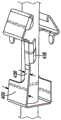
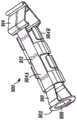
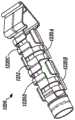
图2A是描绘根据本公开的实施例的处于第一或准备使用位置的安全导管插入组件的立体图。2A is a perspective view depicting the safety catheterization assembly in a first or ready-to-use position, according to an embodiment of the present disclosure.
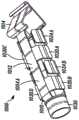
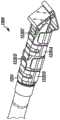
图2B是描绘根据本公开的实施例的处于第二或安全位置的图2A的导管插入组件的立体图。2B is a perspective view depicting the catheterization assembly of FIG. 2A in a second or safety position, according to an embodiment of the present disclosure.
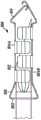
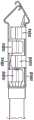
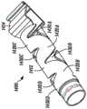
图3是描绘根据本公开的实施例的安全导管插入组件的分解图。3 is an exploded view depicting a safety catheterization assembly according to an embodiment of the present disclosure.
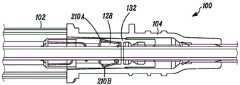
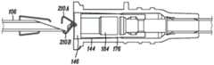
图4A是描绘根据本公开的实施例的处于第一或准备使用位置的导管组件和导管插入装置的局部横截面图。4A is a partial cross-sectional view depicting the catheter assembly and catheter insertion device in a first or ready-to-use position, according to an embodiment of the present disclosure.
图4B是描绘根据本公开的实施例的处于第二或安全位置的图4A的导管组件的局部横截面图。4B is a partial cross-sectional view depicting the catheter assembly of FIG. 4A in a second or safety position, according to an embodiment of the present disclosure.
图5是描绘根据本公开的实施例的致动器的横截面图。5 is a cross-sectional view depicting an actuator according to an embodiment of the present disclosure.
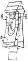
图6A是描绘根据本公开的实施例的密封构件的横截面图。6A is a cross-sectional view depicting a sealing member according to an embodiment of the present disclosure.
图6B是描绘图6A的密封构件的近端视图。6B is a proximal view depicting the sealing member of FIG. 6A.
图7是描绘根据本公开的实施例的导管组件的局部横截面图,该导管组件具有密封构件,该密封构件具有擦拭器和穿过其中的针头套管。7 is a partial cross-sectional view depicting a catheter assembly having a sealing member with a wiper and a needle cannula therethrough in accordance with an embodiment of the present disclosure.
图8A是描绘根据本公开的实施例的导管组件和鲁尔锥的局部横截面图,其中导管组件的密封构件处于闭合位置。8A is a partial cross-sectional view depicting a catheter assembly and a luer with the sealing member of the catheter assembly in a closed position, according to an embodiment of the present disclosure.
图8B是描绘根据本公开的实施例的图8A的导管组件和鲁尔锥的局部横截面图,其中密封构件处于闭合位置与打开位置之间的过渡。8B is a partial cross-sectional view depicting the catheter assembly and Luer cone of FIG. 8A with the sealing member in transition between a closed position and an open position, according to an embodiment of the present disclosure.
图8C是描绘根据本公开的实施例的图8B的导管组件和鲁尔锥的局部横截面图,其中密封构件处于打开位置。8C is a partial cross-sectional view depicting the catheter assembly and Luer cone of FIG. 8B with the sealing member in an open position, according to an embodiment of the present disclosure.
图9A是描绘根据本公开的实施例的安全夹和针头套管的第一实施例的局部立体图,其中安全夹处于第一或准备使用位置。9A is a partial perspective view depicting a first embodiment of a safety clip and a needle cannula with the safety clip in a first or ready-to-use position according to an embodiment of the present disclosure.
图9B是描绘根据本公开的实施例的图9A的安全夹和针头套管的局部立体图,其中安全夹处于第二或安全位置。9B is a partial perspective view depicting the safety clip and needle cannula of FIG. 9A with the safety clip in a second or safety position, according to an embodiment of the present disclosure.
图9C是描绘根据本公开的实施例的处于自由状态的图9B的安全夹的立体图。9C is a perspective view depicting the safety clip of FIG. 9B in a free state according to an embodiment of the present disclosure.
图9D是描绘处于第二或安全位置的图9B的安全夹和针头套管的轮廓图。Figure 9D is a profile view depicting the safety clip and needle cannula of Figure 9B in the second or safety position.
图10A是描绘根据本公开的实施例的安全夹和针头套管的第二实施例的局部立体图,其中安全夹处于第一或准备使用位置。10A is a partial perspective view depicting a second embodiment of a safety clip and a needle cannula with the safety clip in a first or ready-to-use position according to an embodiment of the present disclosure.
图10B是描绘根据本公开的实施例的图10A的安全夹和针头套管的局部立体图,其中安全夹处于第二或安全位置。10B is a partial perspective view depicting the safety clip and needle cannula of FIG. 10A with the safety clip in a second or safety position, according to an embodiment of the present disclosure.
图10C是描绘处于第二或安全位置的图10B的安全夹和针头套管的轮廓图。10C is a profile view depicting the safety clip and needle cannula of FIG. 10B in a second or safety position.
图10D是描绘根据本公开的实施例的具有锥形远侧壁的安全夹和针头套管的局部立体图。10D is a partial perspective view depicting a safety clip with a tapered distal wall and a needle cannula in accordance with an embodiment of the present disclosure.
图10E是描绘根据本公开的实施例的具有扭转的尖齿的安全夹的立体图。10E is a perspective view depicting a safety clip with twisted tines according to an embodiment of the disclosure.
图11A是描绘根据本公开的实施例的安全夹和针头套管的第三实施例的局部立体图,其中安全夹处于第一或准备使用位置。11A is a partial perspective view depicting a third embodiment of a safety clip and a needle cannula according to an embodiment of the present disclosure, with the safety clip in a first or ready-to-use position.
图11B是描绘根据本公开的实施例的图11A的安全夹和针头套管的局部立体图,其中安全夹处于第二或安全位置。11B is a partial perspective view depicting the safety clip and needle cannula of FIG. 11A with the safety clip in a second or safety position, according to an embodiment of the present disclosure.
图11C是描绘处于第二或安全位置的图11B的安全夹和针头套管的轮廓图。11C is a profile view depicting the safety clip and needle cannula of FIG. 11B in a second or safety position.
图11D是描绘处于第一或准备使用位置的图11B的安全夹和针头套管的横截面端视图。11D is a cross-sectional end view depicting the safety clip and needle cannula of FIG. 11B in a first or ready-to-use position.
图12A是描绘根据本公开的实施例的安全夹和针头套管的第四实施例的局部立体图,其中安全夹处于第一或准备使用位置。12A is a partial perspective view depicting a fourth embodiment of a safety clip and needle cannula according to an embodiment of the present disclosure, with the safety clip in a first or ready-to-use position.
图12B是描绘根据本公开的实施例的图12A的安全夹和针头套管的局部立体图,其中安全夹处于第二或安全位置。12B is a partial perspective view depicting the safety clip and needle cannula of FIG. 12A with the safety clip in a second or safety position, according to an embodiment of the present disclosure.
图12C是描绘处于第二或安全位置的图12B的安全夹和针头套管的轮廓图。Figure 12C is a profile view depicting the safety clip and needle cannula of Figure 12B in the second or safety position.
图13A是描绘根据本公开的实施例的安全夹和针头套管的第五实施例的局部立体图,其中安全夹处于第一或准备使用位置。13A is a partial perspective view depicting a fifth embodiment of a safety clip and needle cannula according to an embodiment of the present disclosure, with the safety clip in a first or ready-to-use position.
图13B是描绘根据本公开的实施例的图13A的安全夹和针头套管的局部立体图,其中安全夹处于第二或安全位置。13B is a partial perspective view depicting the safety clip and needle cannula of FIG. 13A with the safety clip in a second or safety position, according to an embodiment of the present disclosure.
图13C是描绘处于第二或安全位置的图13B的安全夹和针头套管的轮廓图。Figure 13C is a profile view depicting the safety clip and needle cannula of Figure 13B in the second or safety position.
图13D是描绘处于第一或准备使用位置的图13B的安全夹和针头套管的横截面端视图。13D is a cross-sectional end view depicting the safety clip and needle cannula of FIG. 13B in a first or ready-to-use position.
图14A是描绘根据本公开的实施例的安全夹和针头套管的第六实施例的局部立体图,其中安全夹处于第一或准备使用位置。14A is a partial perspective view depicting a sixth embodiment of a safety clip and needle cannula according to an embodiment of the present disclosure, with the safety clip in a first or ready-to-use position.
图14B是描绘根据本公开的实施例的图14A的安全夹和针头套管的局部立体图,其中安全夹处于第二或安全位置。14B is a partial perspective view depicting the safety clip and needle cannula of FIG. 14A with the safety clip in a second or safety position, according to an embodiment of the present disclosure.
图15A是描绘根据本公开的实施例的安全夹的第七实施例的立体图。15A is a perspective view depicting a seventh embodiment of a security clip according to an embodiment of the present disclosure.
图15B是描绘根据本公开的实施例的图15A的安全夹以及针头套管的立体图,其中安全夹处于第二或安全位置。15B is a perspective view depicting the safety clip and needle cannula of FIG. 15A with the safety clip in a second or safety position, according to an embodiment of the present disclosure.
图15C是描绘根据本公开的实施例的处于第二或安全位置的图15B的安全夹和针头套管的轮廓图。15C is a profile view depicting the safety clip and needle cannula of FIG. 15B in a second or safety position, according to an embodiment of the present disclosure.
图16A是描绘根据本公开的实施例的安全夹的第八实施例的立体图。16A is a perspective view depicting an eighth embodiment of a security clip according to an embodiment of the present disclosure.
图16B是描绘根据本公开的实施例的图16A的安全夹以及针头套管的立体图,其中安全夹处于第二或安全位置。16B is a perspective view depicting the safety clip and needle cannula of FIG. 16A with the safety clip in a second or safety position, according to an embodiment of the present disclosure.
图16C是描绘根据本公开的实施例的处于第二或安全位置的图16B的安全夹和针头套管的轮廓图。16C is a profile view depicting the safety clip and needle cannula of FIG. 16B in a second or safety position, according to an embodiment of the present disclosure.
图17A是描绘根据本公开的实施例的安全夹的第九实施例的立体图。17A is a perspective view depicting a ninth embodiment of a security clip according to an embodiment of the present disclosure.
图17B是描绘根据本公开的实施例的图17A的安全夹以及针头套管的立体图,其中安全夹处于第二或安全位置。17B is a perspective view depicting the safety clip and needle cannula of FIG. 17A with the safety clip in a second or safety position, according to an embodiment of the present disclosure.
图17C是描绘根据本公开的实施例的处于第二或安全位置的图17B的安全夹和针头套管的轮廓图。17C is a profile view depicting the safety clip and needle cannula of FIG. 17B in a second or safety position, according to an embodiment of the present disclosure.
图18A是描绘根据本公开的实施例的安全夹的第十实施例的立体图。18A is a perspective view depicting a tenth embodiment of a security clip according to an embodiment of the present disclosure.
图18B是描绘根据本公开的实施例的图18A的安全夹以及针头套管的立体图,其中安全夹处于第二或安全位置。Figure 18B is a perspective view depicting the safety clip and needle cannula of Figure 18A with the safety clip in a second or safety position, according to an embodiment of the present disclosure.
图18C是描绘根据本公开的实施例的处于第二或安全位置的图18B的安全夹和针头套管的轮廓图。18C is a profile view depicting the safety clip and needle cannula of FIG. 18B in a second or safety position, according to an embodiment of the present disclosure.
图19A是描绘根据本公开的实施例的安全夹的第十一实施例的立体图。19A is a perspective view depicting an eleventh embodiment of a security clip according to an embodiment of the present disclosure.
图19B是描绘根据本公开的实施例的图19A的安全夹以及针头套管的立体图,其中安全夹处于第二或安全位置。Figure 19B is a perspective view depicting the safety clip and needle cannula of Figure 19A with the safety clip in a second or safety position, according to an embodiment of the present disclosure.
图19C是描绘根据本公开的实施例的处于第二或安全位置的图19B的安全夹和针头套管的轮廓图。19C is a profile view depicting the safety clip and needle cannula of FIG. 19B in a second or safety position, according to an embodiment of the present disclosure.
图20A是描绘根据本公开的实施例的安全夹的第十二实施例的立体图。20A is a perspective view depicting a twelfth embodiment of a security clip according to an embodiment of the present disclosure.
图20B是描绘根据本公开的实施例的图20A的安全夹以及针头套管的立体图,其中安全夹处于第二或安全位置。20B is a perspective view depicting the safety clip of FIG. 20A and the needle cannula with the safety clip in a second or safety position, according to an embodiment of the present disclosure.
图20C是描绘根据本公开的实施例的处于第二或安全位置的图20B的安全夹和针头套管的轮廓图。20C is a profile view depicting the safety clip and needle cannula of FIG. 20B in a second or safety position, according to an embodiment of the present disclosure.
图21A是描绘根据本公开的实施例的安全夹的第十三实施例的立体图。21A is a perspective view depicting a thirteenth embodiment of a security clip according to an embodiment of the present disclosure.
图21B是描绘根据本公开的实施例的图21A的安全夹以及针头套管的立体图,其中安全夹处于第二或安全位置。21B is a perspective view depicting the safety clip of FIG. 21A and the needle cannula with the safety clip in a second or safety position, according to an embodiment of the present disclosure.
图21C是描绘根据本公开的实施例的处于第二或安全位置的图21B的安全夹和针头套管的轮廓图。21C is a profile view depicting the safety clip and needle cannula of FIG. 21B in a second or safety position, according to an embodiment of the present disclosure.
图22A是描绘根据本公开的实施例的处于第一或准备使用位置的安全导管组件的局部横截面图。22A is a partial cross-sectional view depicting a safety catheter assembly in a first or ready-to-use position according to an embodiment of the present disclosure.
图22B是根据本公开的实施例的图22A的安全导管组件的局部横截面图,其中安全导管组件处于在第一或准备使用位置与第二或安全位置之间的过渡。22B is a partial cross-sectional view of the safety catheter assembly of FIG. 22A in transition between a first or ready-to-use position and a second or safety position, according to an embodiment of the present disclosure.
图22C是根据本公开的实施例的图22B的安全导管组件的局部横截面图,其中安全导管组件处于第二门安全位置。22C is a partial cross-sectional view of the safety conduit assembly of FIG. 22B with the safety conduit assembly in a second door safety position, according to an embodiment of the disclosure.
图23A是描绘根据本公开的实施例的近侧杯状体的立体图。23A is a perspective view depicting a proximal cup according to an embodiment of the present disclosure.
图23B是描绘根据本公开的实施例的处于第二或安全位置的针头套管、安全夹和近侧杯状体的局部立体图。23B is a partial perspective view depicting the needle cannula, safety clip, and proximal cup in a second or safety position, according to an embodiment of the present disclosure.
图23C是描绘了根据本公开的实施例处于第二或安全位置的针头套管、安全夹和具有杆延伸部的近侧杯状体的局部立体图。23C is a partial perspective view depicting the needle cannula, safety clip, and proximal cup with stem extension in a second or safety position according to an embodiment of the present disclosure.
图23D是描绘根据本公开的实施例的具有近侧杯状体的安全导管插入组件的局部横截面图,其中安全导管组件处于第一或准备使用位置。23D is a partial cross-sectional view depicting a safety catheterization assembly having a proximal cup in accordance with an embodiment of the present disclosure, wherein the safety catheter assembly is in a first or ready-to-use position.
图23E是描绘根据本公开的实施例的图23D的安全导管插入组件的立体图,其中安全导管组件处于第二或安全位置。23E is a perspective view depicting the safety catheterization assembly of FIG. 23D with the safety catheter assembly in a second or safety position, according to an embodiment of the present disclosure.
尽管本公开的实施例能进行各种修改和替代的形式,但是将详细描述通过附图中的示例示出的其细节。然而应当理解,意图不是将本公开限制到所描述的特定实施例。相反地,意图是涵盖落入由权利要求限定的本主题的精神和范围内的所有修改、等同物和替代物。Although the embodiments of the present disclosure are capable of various modifications and alternative forms, details thereof shown by examples in the accompanying drawings will be described in detail. It should be understood, however, that the intention is not to limit the disclosure to the particular embodiments described. On the contrary, the intention is to cover all modifications, equivalents, and alternatives falling within the spirit and scope of the subject matter defined by the claims.
具体实施方式Detailed ways
本文描述了用于进入受试者的静脉的导管的各种示例实施例。然而,应当理解,本文所述的示例实施例能够可替代地用于在除静脉以外的位置处进入受试者的血管,包括但是不限于受试者的动脉。另外应当理解,术语“临床医生”是指能够利用本文所述的任何示例实施例或者其替代组合来执行导管插入过程的任何个人。类似地,如本文所使用的,术语“受试者”应理解为是指要插入导管的个人或者对象,无论是人类、动物还是无生命的。为了方便起见,本文中进行了关于由临床医生执行的进入受试者的静脉的过程的各种描述,而本公开不限于该方面。Various example embodiments of catheters for accessing a vein of a subject are described herein. It should be understood, however, that the example embodiments described herein can alternatively be used to access a subject's blood vessels at locations other than veins, including, but not limited to, a subject's arteries. It should also be understood that the term "clinician" refers to any individual capable of performing a catheterization procedure using any of the example embodiments described herein, or alternative combinations thereof. Similarly, as used herein, the term "subject" should be understood to mean a person or subject, whether human, animal or inanimate, who is to be catheterized. For convenience, various descriptions herein are made regarding the procedure performed by a clinician to access a subject's vein, and the present disclosure is not limited in this respect.
还应理解,如本文所使用的,术语“远侧”是指在导管插入期间、沿着平行于安全导管组件的针头套管的轴线、最邻近受试者的方向。相反,如本文所使用的,术语“近侧”是指与远端方向相反的、当将导管插入受试者的静脉中时沿着平行于针头套管的轴线、更远离受试者的方向。It will also be understood that, as used herein, the term "distal" refers to the direction closest to the subject during catheterization along an axis parallel to the needle cannula of the safety catheter assembly. In contrast, as used herein, the term "proximal" refers to a direction, as opposed to the distal direction, farther from the subject along an axis parallel to the needle cannula when the catheter is inserted into the subject's vein .
参考考图1A至图1B,描绘了常规的导管插入组件50。常规的导管插入组件50的细节在上面的背景技术部分中描述。Referring to FIGS. 1A-1B , a
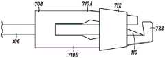
参考图2A至图2B,描绘了根据本公开的实施例的安全导管插入组件100的立体图。图3描绘了根据本公开的实施例的安全导管插入组件100的分解图。安全导管组件100能够包括导管插入装置102和导管组件104。导管插入装置102能够包括可操作地耦接到针头接口108的插入物或者针头套管106。针头套管106能够包括细长的圆柱形金属结构,该结构限定了在尖锐的远侧针头尖端110与近端112之间延伸的管腔。尖锐的远侧针头尖端110能够被构造和布置成在导管插入期间刺穿受试者的皮肤。例如,在一个实施例中,尖锐的远侧尖端110能够包括V点,该V点设计成减小用于将针头106和导管插入组件104的一部分穿刺通过受试者的皮肤、组织和静脉壁的穿刺力。在一个实施例中,针头106的长度能够延伸以帮助将导管组件104插入肥胖患者体内。Referring to FIGS. 2A-2B , perspective views of a
针头套管106还能够包括过渡部114,过渡部114具有与定位在过渡部114近侧的、针头106的其他部分不同的横截面大小和形状。针头过渡部114(可替代地称为针头凸起或者套管凸起)能够通过压接针头套管106的相对侧或者以其他方式破坏针头106的结构而产生,使得从针头轴线的中心测量,针头106的外表面延伸到比针头套管106的其他部分更大的径向位置。根据替代实施例,针头过渡部114能够不同地形成,诸如通过向针头的外部添加材料等。
针头套管106的近端112能够可操作地耦接到针头接口108。针头接口108能够包括用于由临床医生操纵的抓握部。在一个实施例中,导管插入装置102能够构造成当针头106的尖锐的远侧尖端110进入受试者的静脉时提供闪回的视觉指示。在该实施例中,针头接口108包括与针头的管腔流体连通的闪发室116。当尖锐的远侧尖端110在导管插入期间进入静脉时,血液或者体液从静脉进入针腔并且向近侧通过针头106流入闪发室116中。闪发室116能够在一个端部处由闪发塞118密封。闪发塞118能够由透气的亲水材料制成,该亲水材料能够使空气通过,但是阻止液体通过。因此,驻留在针腔和闪发室116中的空气被进入的血液推动通过闪发塞118,直到血液到达闪发塞118或者以其他方式停止。针头接口108或者其部分能够由透明或者半透明的材料构成,该透明或者半透明的材料被配置成使临床医生能够观察闪发室116内的血液的存在。在这方面,当针头已经进入受试者的静脉时,能够通过闪发室116中的血液的存在警告临床医生。The
在一个实施例中,除闪发室116以外的、导管插入装置102的特征能够提供尖锐的远侧尖端110已经进入受试者的静脉的指示。例如,针头套管106能够包括凹口120。在该实施例中,当尖锐的远侧尖端110进入静脉时,血流进入针腔。当血液在针腔中朝近侧流动时,一些血液穿过凹口120并进入位于针头106的外部与导管组件104的内部之间的环形空间。临床医生能够通过导管组件104的透明或者半透明部分观察到环形空间中血液的存在,从而提供了尖锐的远侧尖端110存在于静脉中的指示。In one embodiment, features of
如图2A中所描绘的,安全导管插入组件100能够设置在第一或准备使用位置,在该位置处导管组件104连接到导管插入装置102。特别地,导管组件104(能够包括导管接口122和导管管部124)能够定位在导管插入装置102的针头套管106上方,其中针头106的尖锐的远侧尖端110从导管管部124的远端126突出。在一些实施例中,安全导管组件100能够被提供为在无菌和组装状态中使用,包含在密封包装内。As depicted in FIG. 2A ,
为了将导管插入受试者的静脉中,临床医生首先从包装中取出安全导管组件100。覆盖针头套管106的针头护套125(如图3中所描绘的)能够被移除以暴露针头套管106的尖锐的远侧尖端110。然后,临床医生用锐利的远侧尖端110穿刺在患者或者受试者上的已识别部位并且向前推动针头套管106,直到尖锐的远侧尖端110和导管管部124的一部分进入受试者的静脉。To catheterize a subject's vein, the clinician first removes
导管组件104然后能够在针头106上方向远侧移动,由于导管插入装置102保持静止,因此将导管组件104穿入受试者的静脉。在导管组件104如期望地定位的情况下,临床医生能够通过将导管插入装置102远离受试者朝近侧拉动,同时将导管组件104相对于受试者大致保持静止,而从患者的静脉抽出针头套管106。朝近侧拉动导管插入装置102,直到针头套管106与导管组件104分开为止。
如图2B中所描绘的,导管插入装置102能够根据第二或安全位置从导管组件104分开或者移除。在一些实施例中,为了阻止不想要的针头刺伤,在将导管插入装置102与导管组件104分开之前,安全夹128能够可操作地耦接到导管组件104和/或导管插入装置102中的任一个,并且定位在尖锐的远侧尖端110上方。在安全位置处,临床医生能够将导管插入装置102布置在尖锐的容器中。As depicted in FIG. 2B ,
参考图4A,描绘了根据本公开的实施例的处于第一或准备使用位置的安全导管组件100的局部横截面图。参考图4B,描绘了根据本公开的实施例的处于第二位置的导管组件104的局部横截面图。导管组件104能够包括导管接口122、导管管部124、安全夹128、致动器130和密封构件132。在一些实施例中,导管组件104还能够包括翼组件、延伸管、延伸管夹、无针头连接器和/或通风盖(未描绘)。因此,导管组件104能够包括血液控制特征,该血液控制特征被配置成在抽出针头套管106之后阻止血液逸出,从而降低血液或者其他体液暴露于临床医生的风险,特别是考虑到可能存在血液传播疾病时的敏感性。另外,导管组件104的实施例能够在连接到IV流体供应之前阻止将不想要的污染物引入导管组件104的内部。Referring to FIG. 4A , a partial cross-sectional view of
导管管部124能够从锥形远端126延伸到近端134,在近端134处导管管部124能够可操作地耦接到导管接口122。导管管部124能够限定管腔136,该管腔136被配置成在受试者的静脉与导管接口122之间提供流体路径。在一个实施例中,导管管部124能够包括不透明线的钡射线,以在放射过程期间容易地识别导管管部124。
导管接口122能够包括导管接口主体138,该导管接口主体138具有远端140、近端142和在其间限定内部腔体146的内壁144。内部腔体能够包括从开口的近端142延伸的近侧部分148,以及更接近远端140的远侧部分150。在一个实施例中,导管接口主体138的远端140可操作地耦接到导管管部124的近端134,使得导管管部124的管腔136与内部腔体146的近侧部分148流体连通。内部腔体146的近侧部分148根据鲁尔锥标准成形,以匹配地接收鲁尔锥200(如图8A-图8C中所描绘的)。
致动器130能够被固定在导管接口122的远端140的近侧,以便在内部腔体146内轴向地延伸。在一个实施例中,导管管部124的近端134能够借助于致动器130被固定在导管接口122的内部腔体146内。还能够借助于致动器130将密封构件132(可替代地称为血液控制阀132)固定在导管接口122的内部腔体146内,使得密封构件132能相对于致动器130在闭合或者密封位置与打开或者致动位置之间轴向移位。因此,致动器130既用于将导管管部124固定到导管接口122,又用于支撑密封构件132。
参考图5,描绘了根据本公开的实施例的致动器130的横截面图。致动器130能够是大致刚性的,并且能够包括大致圆柱形主体152,该大致圆柱形主体152具有远端154、近端156和在其间限定内部腔体160的壁158。例如,在一个实施例中,致动器130能够通过通常本领域已知的方法由医用级不锈钢形成。在一个实施例中,内部腔体160配置成在不干扰针头过渡部114的情况下接收穿过其中的针头套管106。在抽回针头套管时,内部腔体160能够配置成使体液从中通过。在一个实施例中,壁158能够进一步限定环形肋162,该环形肋162将圆柱形主体152分成远侧部分164和近侧部分166。在一些实施例中,远端154能够是锥形的,并且近端156能够包括凸缘168。在一个实施例中,能够通过以大于90°的角度弯曲或者折叠壁158的一部分来形成凸缘168,使得在一些实施例中,使壁158的一部分在其自身上向后折叠。Referring to FIG. 5 , a cross-sectional view of
如图4A-图4B中所描绘的,致动器130的远侧部分164能够在导管管部124的近端134内摩擦配合,其能够在导管接口122的内部腔体146内摩擦配合,使得导管管部124从导管接口122的远端140向远侧延伸。环形肋162能够用于增强致动器130在导管接口122的内部腔体146内的摩擦配合。因此,致动器130能够定位在导管接口内,使得自由近侧部分166在导管接口122的内部腔体146内向近侧延伸。As depicted in FIGS. 4A-4B , the
如图4A-图4B中所描绘的,密封构件132(即血液控制阀)布置在导管接口122的内部腔体146内,并且部分地由致动器130支撑和部分地由导管接口122的内壁144支撑在其中,使得密封构件132能够在闭合位置与打开位置之间移位,在该闭合位置处,体液从导管管部124到导管接口122的内部腔体146的流动被阻止或者限制,在打开位置处,密封构件132相对于致动器130移位,从而使体液从导管管部124流入导管接口122的内部腔体146的近侧部分148,如将在下面进一步详细说明地。As depicted in FIGS. 4A-4B , sealing member 132 (i.e., blood control valve) is disposed within
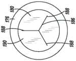
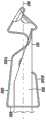
参考图6A,描绘了根据本公开的实施例的密封构件132的横截面图。参考图6B,描绘了根据本公开的实施例的密封构件132的近端视图。密封构件132能够是大致弹性的或者回弹性的,并且能够包括大致圆柱形主体170,该大致圆柱形主体170具有远端172、近端174以及在其间限定内部腔体178的壁176。在一个实施例中,密封构件132能够通过本领域中通常已知的方法由合适的材料(包括例如硅胶或者聚异戊二烯)形成。Referring to FIG. 6A , a cross-sectional view of sealing
在一个实施例中,壁176还能够包括将内部腔体178分成远侧部分182和近侧部分184的膜180。在一个实施例中,膜180能够基本与圆柱形主体170的中心纵向轴线正交地延伸。膜180能够限定狭缝186,当密封构件132处于松弛的未压缩状态时,狭缝186能够被正常地偏置闭合。狭缝186能够采用本领域公认的几种形式,并且例如能够是穿过膜180的单个直的狭缝(未示出)。如图6B中所描绘的,在一个实施例中,狭缝186能够具有三狭缝配置,该三狭缝配置延伸到三个径向最外端188以呈现大致Y形配置。狭缝186限定了多个膜瓣片190,该多个膜瓣片190的数量取决于狭缝186的特定配置(例如,用于三狭缝配置的三个瓣片190)。In one embodiment, the
在一个实施例中,狭缝186的形状和大小能够设计成紧密符合针头套管106的外径,以便阻止泄漏,特别是在针头套管106向近侧抽回期间,并且不增加从导管接口122抽回针头套管106所需的致动力。例如,在一些实施例中,狭缝186的长度(例如,其径向范围)能够非常近似14号针头(0.06525英寸)、16号针头(0.05025英寸)、18号针头(0.03575英寸)或者20号针头(0.02825英寸)的宽度。在一些实施例中,狭缝186的长度能够测量为近似0.075英寸、0.070英寸、0.060英寸、0.055英寸、0.045英寸、0.040英寸或者0.035英寸。另外,狭缝186的长度优选地小于膜180的横截面尺寸(例如,直径),使得狭缝186的径向最外端188与圆柱形主体170的壁176间隔开,并且狭缝186不穿刺入圆柱形主体170的壁176中。In one embodiment, the shape and size of the
在安全导管组件100的第一或准备使用位置处(如图4A中所描绘的),膜180中的狭缝186和针头套管106能够协作以当针头套管106延伸穿过膜180时,阻止或者限制体液围绕针头套管106的外径的流动。在一些实施例中,狭缝186和针头套管106可以不形成流体紧密的密封,而是可以对穿过其中的体液的流动提供显著的限制,使得在将导管管部124插入患者的脉管系统期间,少量的血液可以渗过膜180的狭缝196。在另一个实施例中,密封构件132能够包括第二膜或者擦拭器202,该第二膜或者擦拭器202被配置成进一步限制或者阻止体液的流动并且通常在前进期间改善密封。In the first or ready-to-use position of safety catheter assembly 100 (as depicted in FIG. 4A ), slit 186 in
参考图7,描绘了根据本公开的实施例的导管组件104的局部横截面图,该导管组件104具有带有擦拭器202的密封构件132和穿过其中的针头套管106。在一个实施例中,擦拭器202能够被配置成限定孔口206的膜204。在一个实施例中,孔口206能够是圆形的。与在移除针头套管106时通常能够偏置地闭合的狭缝186相反,孔口206能够具有略小于针头套管106的外径的横截面尺寸,并且因此,尽管当针头套管106定位在密封构件132内时紧密地与针头套管106的外径紧密符合和/或与针头套管106的外径轻微干涉,但是当针头套管106被移除时,孔口206能够保持打开。在一个实施例中,擦拭器202定位在膜180的远侧,从而当针头套管106定位在密封构件132内时阻止体液流到膜180。在其他实施例中,擦拭器202能够定位在膜的近侧。Referring to FIG. 7 , a partial cross-sectional view of
继续参考图6A,内部腔体178的远侧部分182能够包括由从远端172向内延伸的环形密封唇缘194限定的密封出口孔192,以及在密封出口孔192与膜180之间的致动器腔体196。另外参考图8A,描绘了根据本公开的实施例的导管组件104的横截面图,其中密封构件132处于闭合位置。致动器的近侧部分166能通过密封出口孔192接收并且进入到致动器腔体196中,其中凸缘168包含在致动器腔体196中。致动器腔体196能够包括变窄部分198,该变窄部分198为致动器腔体196提供沙漏形状。在一个实施例中,变窄部分196能够由环形肋提供,该环形肋从壁176的、限定致动器腔体196的部分大致径向向内突出。在一个实施例中,凸缘168完全包含在致动器腔体196内。例如,在一个实施例中,密封构件132的凸缘168的截头圆锥形表面能够与变窄部分198的环形肋接合。凸缘168具有的最外横截面直径能够大于密封出口孔192的横截面直径,并且能够配置成使密封出口孔192能够在凸缘168上向远侧滑动,但是限制密封构件132向近侧移动回到凸缘168上。因此,在闭合位置(如图8A中所描绘的)处,当凸缘168定位在致动器腔体196内时,膜180的狭缝186能够自然地偏置闭合,以阻止流体从中流过。With continued reference to FIG. 6A , the
如图8B-图8C中所描绘的,在插入鲁尔锥200时,密封构件132能够相对于致动器130向远侧移位,以便使凸缘168抵靠膜180推动,从而使膜180的狭缝186至少部分打开。内部腔体178的近侧部分184能够是大致圆柱形的,并且能够在膜180与密封构件132的近端174中的开口之间延伸。在一个实施例中,近侧部分184能够具有大致恒定的横截面尺寸,该横截面尺寸被配置成使得标准尺寸的鲁尔锥200不能进入密封构件132的内部腔体178,而替代地是最多将抵靠密封构件132的近端174冲击。As depicted in FIGS. 8B-8C , upon insertion of
当密封构件132在导管接口122内轴向移位时,致动器130的近侧部分166接触膜180并且开始穿刺通过狭缝186,从而使由狭缝186形成的瓣片190铰接或者张开并且沿着凸缘168(例如,沿着其截头圆锥形表面)滑动,以便逐渐打开狭缝186。鲁尔锥200的继续向远侧插入使密封构件132轴向移位,直到鲁尔锥200完全延伸到导管接口122的内部腔体146中,其中密封构件132的远端172向前移动或者抵靠内部腔体146的远侧部分150,从而限定了密封构件132的打开位置(如图8C中所描绘的)。当密封构件132处于打开位置时,经由致动器130在导管管部124与鲁尔锥200之间形成畅通的流体路径,诸如用于通过导管组件104将流体施加到患者或者通过导管组件104从患者抽出血液或者其他体液。As sealing
在一个实施例中,膜180具有足够的回弹性,使得凸缘168能够穿刺狭缝186而不会撕裂或者以其他方式破坏膜180。在凸缘168穿过致动器130之后,狭缝186能够接着围绕致动器130向后闭合。在另一个实施例中,当凸缘168穿刺通过狭缝186时,能够使膜180变形、裂开或者以其他方式破坏。因此,在一个实施例中,密封构件132是一次性密封件。就这一点而言,在从导管接口122移除鲁尔锥200之后,密封构件132将不会向近侧移动回到闭合位置,而替代地是将保持在打开位置。在一个实施例中,凸缘168能够配置成使密封构件132能够朝向远侧移动,但是阻止密封构件132相反的、朝向近侧移动。因此,在一个实施例中,膜180不会自动地在凸缘168上移回以关闭所形成的流体流动路径,而替代地是在导管管部124与内部腔体146和/或导管接口122的开口近端142之间提供了畅通的流体流动路径。在另一个实施例中,导管组件104能够提供有机构,诸如弹簧、弹性件或者波纹管,以提供使密封构件132朝向近侧、轴向移位回的驱动力,以便将密封构件132移位到闭合位置。在一个实施例中,配置成提供使密封构件132朝向近侧、轴向移位回的驱动力的机构能够与密封件成一体。In one embodiment, the
安全夹128能够至少部分地驻留在密封构件132的近侧部分184内,并且能够被配置成在第一或准备使用位置(如图2A中所描绘的)与第二或安全位置(如图2B中所描绘的)之间、沿着针头套管106轴向滑动,在所述第一或准备使用位置处针头套管106穿过安全夹128,在所述第二或安全位置处锐利的远侧尖端110被捕获在安全夹128内,以阻止不想要的针头刺伤。The
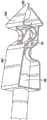
参考图9A-图9D,描绘了根据本公开的实施例的安全夹的第一实施例。图9A描绘了处于第一或准备使用位置的安全夹128,其中针头套管106穿过安全夹128的部分。图9B描绘了处于第二或安全位置的安全夹128,其中针头套管106的尖锐的远侧尖端110被捕获在安全夹128内。Referring to FIGS. 9A-9D , a first embodiment of a security clip according to an embodiment of the present disclosure is depicted. FIG. 9A depicts the
在一个实施例中,安全夹128能够包括近侧壁208和一个或多个防护臂210。近侧壁208能够限定孔口212,孔口212被配置成围绕针头套管106定位或者定位在其上。在一些实施例中,近侧壁208和孔口212能够配置成接合针头过渡部114,以阻止安全夹128离开针头套管106的尖锐的远侧尖端110向远侧前进。在一个实施例中,近侧壁208的表面214能够大致与针头套管106的纵向轴线216正交。在其他实施例中,表面214能够相对于针头套管106的纵向轴线216以斜角或者锐角定位。In one embodiment, the
一个或多个防护臂210能够从近侧壁208向远侧延伸。在一个实施例中,安全夹128能够包括一对防护臂210A/210B。安全夹128能够由通常具有回弹性的材料(例如医用级不锈钢)形成,使得当安全夹128的部分偏离自由状态时,防护臂210具有朝向自由或者松弛状态的自然偏置。例如,在一个实施例中,当安全夹128处于第二或安全位置时,安全夹128处于自由状态。因此,在该实施例中,当安全夹128处于第一或准备使用位置时,防护臂210A-B被偏置抵靠针头套管106,因为针头套管106的存在使防护臂210A-B偏离其自由状态。当缩回针头套管106并且尖锐的远侧尖端110在防护臂210之间向近侧移动时,防护臂210自然地朝向其自由状态偏置,从而在其间捕获尖锐的远侧尖端110。在一些实施例中,通过使针头过渡部114的横截面尺寸大于安全夹的近侧壁中的孔口212,阻止尖锐的远侧尖端110的进一步的向近侧移动。在一些实施例中,尖锐的远侧尖端110的向远侧移动被臂210A-B中的至少一个的远侧部分阻止。One or
在一个实施例中,第一防护臂210A能够包括直线部分218、弯曲部分220和远侧壁222。直线部分218能够与近侧壁208相邻,使得直线部分218和近侧壁208被弯曲部224分开。在一个实施例中,弯曲部224能够形成80-90°的角度,尽管弯曲部224的其他角度也是预期的。In one embodiment, the
弯曲部分220能够与直线部分218相邻。在一些实施例中,弯曲部分220能够具有相对于直线部分218的宽度228减小的宽度226,使得弯曲部分220至少部分地符合针头套管106的外径。在一个实施例中,弯曲部分220能够进一步限定配置成至少部分地符合针头套管106的针头套管引导表面或者轮廓切割部230。因此,弯曲部分220的减小的宽度226和轮廓切割部230能够配置成维持安全夹128沿着针头套管106的位置,特别是当相对于安全夹128缩回针头套管106和使针头套管106移动时。在一个实施例中,当针头套管106定位在安全夹218内时,弯曲部分220的顶点231能够朝向针头套管106的纵向轴线216延伸。在一些实施例中,顶点231仅在第二或安全位置处延伸超过针头套管106的纵向轴线216,并且在第一或者准备使用位置中不延伸超过该纵向轴线216。因此,在一些实施例中,防护臂210A-B是不相交的(即,防护臂210A-B沿着针头套管106的纵向轴线216彼此不交叉或者不相交)。注意,不相交的防护臂(即,沿针头套管106的纵向轴线彼此不交叉或者不相交的防护臂)能够应用于本文公开的针头夹的任何实施例。The
远侧壁222能够与弯曲部分220相邻。在一些实施例中,当针头套管106定位在安全夹218内时,远侧壁222能够朝向针头套管106的纵向轴线216成角度。在一个实施例中,远侧壁222还能够包括在远侧壁222的远端上的唇缘或者钩232。在一个实施例中,钩232能够包括弯曲的表面,该弯曲的表面被配置成当针头套管106被定位在安全夹218内时接触针头套管106和/或沿针头套管106滑动。在一个实施例中,钩232能够被配置成一旦针头套管106的尖锐的远侧尖端110向近侧移动经过钩232,则阻止尖锐的远侧尖端110向远侧移回经过钩232并且移出安全夹128。The
远侧壁还能够包括定位在远侧壁222的任一横向侧上的一个或多个凸片234,使得该一个或多个凸片234能够被配置成用于帮助保持针头套管106的尖锐的远侧尖端110处于第二或安全位置。该一个或多个凸片234能够另外用于接触相对的防护臂210B的一部分,以为了维持防护臂210A-B在第二或安全位置处的对准。The distal wall can also include one or
在一个实施例中,第二防护臂210B还能够包括具有与第一防护臂210A的配置相似的配置的直线部分218B、弯曲部分220B和远侧壁222B。在一些实施例中,第二防护臂210B能够比第一防护臂201A略短一些,使得在第二或安全位置处,第二防护臂210B的钩232B能够定位在第一防护臂210A的钩232的近侧。另外,在一些实施例中,第二防护臂210B的弯曲部分220B能够被定位成在第一防护臂210A的弯曲部分220的近侧,使得在第二或安全位置处,防护臂210A-B是不相交的(即,防护臂210A-B沿着针头套管106的纵向轴线216彼此不交叉或者不相交)。在一个实施例中,第二防护臂210B的弯曲部分220B的宽度226能够定位在与第一防护臂210A的弯曲部分220A的宽度226相反的横向侧上,以便阻止防护臂210A-B在第二或安全位置处相交。In one embodiment, the
参考图10A-图10C,描绘了根据本公开的安全夹300的第二实施例。图10A描绘了处于第一或准备使用位置的安全夹300,其中针头套管106穿过安全夹300的部分。图10B描绘了处于第二或安全位置的安全夹300,其中针头套管106的尖锐的远侧尖端110被捕获在安全夹300内。Referring to FIGS. 10A-10C , a second embodiment of a
在一个实施例中,安全夹300能够包括近侧壁308和一个或多个防护臂310A-B。防护臂310能够包括直线部分318、弯曲部分320和远侧壁322。在一个实施例中,安全夹300的弯曲部分320能够在防护臂310A的横向边缘336、338之间限定针头套管引导表面或者轮廓切割部凹口330,使得弯曲部分330形成一对弯曲的尖齿340、342,所述一对弯曲的尖齿340、342具有与直线部分318的宽度328相比总体上减小的宽度326A/B。轮廓切割部凹口330能够被配置成维持安全夹300沿着针头套管106的位置,特别是当相对于安全夹300缩回针头套管106和使针头套管106移动时。安全夹300的其他部分能够类似于在本文公开的其他安全夹实施例中的结构。In one embodiment, the
参考图10D,在替代配置中,安全夹300’的远侧壁322能够具有减小的宽度,以便大致形成远侧锥体350。在这种配置中,远侧锥体350能够用于帮助装载和包含针头套管106的尖锐的远侧尖端110。Referring to Figure 10D, in an alternative configuration, the
参考图10E,在又一配置中,安全夹300”的尖齿340、342能够包括相对于直线部分318的扭转部或者部分转动部。在此配置中,尖齿340、342能够更紧密符合针头套管106的表面,特别是当相对于针头夹300”缩回针头套管106和使针头套管106移动时,从而用于帮助维持安全夹300”沿着针头套管106的位置。Referring to Figure 10E, in yet another configuration, the
参考图11A-图11D,描绘了根据本公开的安全夹400的第三实施例。图11A描绘了处于第一或准备使用位置的安全夹400,其中针头套管106穿过安全夹400的部分。图11B描绘了处于第二或安全位置的安全夹400,其中针头套管106的尖锐的远侧尖端110被捕获在安全夹400内。Referring to FIGS. 11A-11D , a third embodiment of a
在一个实施例中,安全夹400能够包括近侧壁408和一个或多个防护臂410A-B。防护臂410A-B能够包括直线部分418、带凸片的部分420和远侧壁422。直线部分418能够与近侧壁408相邻,使得直线部分418和近侧壁408通过弯曲部424分开。在一个实施例中,弯曲部424能够形成70-90°的角度,尽管弯曲部424的其他角度也是预期的。In one embodiment, the
带凸片的部分420能够与直线部分418相邻。在一些实施例中,带凸片的部分420能够具有相对于直线部分418的宽度428减小的宽度426。在一个实施例中,带凸片的部分420能够包括一个或多个凸片436。该一个或多个凸片436能够被配置成维持安全夹400沿着针头套管106的位置,特别是当相对于安全夹400缩回针头套管106和使针头套管106移动时。在一个实施例中,在第二或安全位置处,带凸片的部分420包含针头套管106。在一个实施例中,当针头套管106定位在安全夹400内时,带凸片的部分420的延伸表面431能够朝向针头套管106的纵向轴线216延伸。在一些实施例中,延伸表面431仅在第二或安全位置处延伸超过针头套管106的纵向轴线216,并且在第一或准备使用位置处不延伸超过纵向轴线216。因此,在一些实施例中,防护臂410A-B是不相交的(即,防护臂410A-B沿着针头套管106的纵向轴线216彼此不交叉或者不相交)。The tabbed
如图11D中所描绘的,在一个实施例中,第二防护臂410B的带凸片的部分420B能够与第一防护臂410A的带凸片的部分420A对准,而第二防护臂210B的凸片436B定位在与第一防护臂410A的凸片436A相反的横向侧上,以便阻止防护臂410A-B在第二或安全位置处相交。安全夹400的其他部分能够类似于本文公开的其他安全夹实施例中的结构。As depicted in FIG. 11D , in one embodiment, the tabbed portion 420B of the
参考图12A-图12C,描绘了根据本公开的安全夹500的第四实施例。图12A描绘了处于第一或准备使用位置的安全夹500,其中针头套管106穿过安全夹500的部分。图12B描绘了处于第二或安全位置的安全夹500,其中针头套管106的尖锐的远侧尖端110被捕获在安全夹500内。Referring to FIGS. 12A-12C , a fourth embodiment of a
在一个实施例中,安全夹500能够包括近侧壁508和一个或多个防护臂510A-B。防护臂510A-B能够包括直线部分518、带凸片的部分520和远侧壁522。在一个实施例中,带凸片的部分520能够存在于防护臂510A和防护臂510B两者上。在其他实施例中,带凸片的部分520能够存在于单个防护臂510A/B上。在一个实施例中,安全夹500的带凸片的部分520能够在防护臂510A的横向边缘536、538之间限定针头套管引导表面或者轮廓切割部凹口530,使得带凸片的部分520形成一对尖齿540、542,该对尖齿540、542与直线部分518的宽度528相比具有整体减小的宽度526A/B。轮廓切割部凹口530和/或带凸片的部分520能够配置成维持安全夹500沿着针头套管106的位置,特别是在相对于安全夹500缩回针头套管106和使针头套管106移动时,和/或在接近或者处于第二或安全位置时。安全夹500的其他部分能够类似于本文公开的其他安全夹实施例中的结构。In one embodiment, the
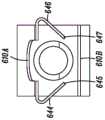
参考图13A-D,描绘了根据本公开的安全夹600的第五实施例。图13A描绘了处于第一或准备使用位置的安全夹600,其中针头套管106穿过安全夹600的部分。图13B描绘了处于第二或安全位置的安全夹600,其中针头套管106的尖锐的远侧尖端110被捕获在安全夹600内。Referring to Figures 13A-D, a fifth embodiment of a
类似于第四实施例,第一防护臂610A能够包括在防护臂610A的横向边缘636、638之间限定针头套管引导表面或者轮廓切割部凹口630的带凸片的部分620,使得带凸片的部分630形成一对尖齿640、642。在该实施例中,一对凸片644、646能够被配置成维持安全夹600沿着针头套管106的位置,特别是当相对于安全夹600缩回针头套管106和使针头套管106移动时。在一个实施例中,当将针头套管106定位在安全夹600内时,凸片644、646的最外表面645、647能够朝向针头套管106的纵向轴线216延伸。在一些实施例中,表面645、647仅在第二或安全位置处延伸超过针头套管106的纵向轴线216,并且在第一或准备使用位置处不延伸超过纵向轴线216。在一些实施例中,第二防护臂610B不包括任何凸片。因此,在一些实施例中,防护臂610A-B是不相交的(即,防护臂610A-B沿着针头套管106的纵向轴线216彼此不交叉或者不相交)。Similar to the fourth embodiment, the
参考图14A-图14B,描绘了根据本公开的安全夹700的第六实施例。图14A描绘了处于第一或准备使用位置的安全夹700,其中针头套管106穿过安全夹700的部分。图14B描绘了处于第二或安全位置的安全夹700,其中针头套管106的尖锐的远侧尖端110被捕获在安全夹700内。Referring to FIGS. 14A-14B , a sixth embodiment of a
在一个实施例中,安全夹700能够包括近侧壁708、一对防护臂710A-B和围绕防护臂700A-B定位的弹性体带712,以便使防护臂700A-B朝向彼此偏置。如在先前的实施例中一样,近侧臂708能够限定孔口,该孔口的形状和大小设计为使得针头套管106的至少一部分能够穿过其中,但是阻止针头过渡部114穿过其中,从而阻止安全夹700离开针头套管106的尖锐的远侧尖端110向远侧前进。In one embodiment, the
防护臂710A-B能够从近侧壁708向远侧延伸,并且能够由大致柔性的材料形成,使得防护臂710A-B能大致相对于近侧壁708枢转。弹性体带712能够围绕防护臂710A-B的一部分定位,从而提供防护臂710A-B朝向彼此偏置。因此,在该实施例中,当安全夹128处于第一或准备使用位置时,防护臂710A-B被偏置抵靠针头套管106。在一个实施例中,防护臂710B之一能够包括远侧壁722,该远侧壁722配置成在针头套管106缩回并且防护臂710A-B朝向彼此偏置并且移位至第二安全位置时阻止针头套管106的前进,从而安全地捕获针头套管106的尖锐的远侧尖端110在安全夹700内。Guard arms 710A-B can extend distally from
参考图15A-图15C,描绘了根据本公开的安全夹800的第七实施例。图15A单独描绘了安全夹800或者描绘了与针头套管106分开的安全夹800。图15B-图15C描绘了安全夹800和第二或安全位置,其中针头套管106的尖锐的远侧尖端110被捕获在安全夹800内。Referring to FIGS. 15A-15C , a seventh embodiment of a
在一个实施例中,安全夹800能够包括近侧臂802和一个或多个防护臂804。近侧臂802能够限定孔口806,该孔口806被配置成围绕针头套管106定位或者定位在其上。在一些实施例中,近侧臂802和孔口806能够配置成与针头过渡部114接合以阻止安全夹800离开针头套管106的尖锐的远侧尖端110向远侧前进。在一个实施例中,近侧壁802的表面808能够基本上与针头套管106的纵向轴线正交。在其他实施例中,表面808能够相对于针头套管106的纵向轴线以斜角或者锐角定位。In one embodiment,
一个或多个防护臂804能够从近侧臂802向远侧延伸。在一个实施例中,安全夹800能够包括一对防护臂804A/804B。安全夹800能够由通常具有回弹性的材料(例如医用级不锈钢)形成(例如,冲压),使得当安全夹800的一部分偏离自由状态时,防护臂804具有朝向自由或者松弛状态的自然偏置。例如,在一个实施例中,当安全夹800处于第二或安全位置时,安全夹800处于自由状态。因此,在该实施例中,当安全夹800处于第一或准备使用位置时,防护臂804A/B被偏置抵靠针头套管106,因为针头套管106的存在使防护臂804A/B偏离其自由状态。当缩回针头套管106并且尖锐的远侧尖端110在防护臂804A/B之间向近侧移动时,防护臂804A/B自然地朝向其自由状态偏置,从而在其间捕获尖锐的远侧尖端110。在一些实施例中,通过使针头过渡部114的横截面尺寸大于安全夹800的近侧壁802中的孔口806,阻止尖锐的远侧尖端110的进一步的向近侧移动。在一些实施例中,尖锐的远侧尖端110的向远侧移动被臂804A/B中的至少一个臂的远侧部分阻止。One or
在一个实施例中,第一防护臂804A能够包括近侧部分810、直线部分812和远侧壁814。近侧部分810能够与近侧壁802相邻,使得近侧部分810和近侧壁802由弯曲部816分开。在一个实施例中,弯曲部816能够形成约60-110°的角度,尽管弯曲部816的其他角度也是预期的。In one embodiment, the first guard arm 804A can include a
直线部分812能够与近侧部分810相邻,使得直线部分812和近侧部分810通过第二弯曲部818分开。在一个实施例中,弯曲部818能够形成约90-180°的角度,尽管弯曲部818的其他角度也是预期的。在一个实施例中,直线部分812能够包括定位在直线部分812的任一横向侧上的一个或多个凸片820A-D,使得凸片820A-D被配置成至少部分地符合针头套管106的外径。因此,直线部分812的一个或多个凸片820A-D能够配置成维持安全夹800沿着针头套管106的位置,特别是当相对于安全夹800缩回针头套管106和使针头套管106移动时。The
远侧壁814能够与直线部分812相邻。在一些实施例中,当针头套管定位在安全夹800内时,远侧壁814能够朝向针头套管的纵向轴线成角度。在一个实施例中,远侧壁814还能够包括在远侧壁814的远端上的唇缘或者钩822。在一个实施例中,钩822能够包括弯曲表面,该弯曲表面配置成当针头套管106定位在安全夹800内时,接触针头套管106和/或沿针头套管106滑动。在一个实施例中,钩822能够被配置成一旦针头套管106的尖锐的远侧尖端110向近侧移动经过钩822,则阻止尖锐的远侧尖端110向远侧移回经过钩822并且移出安全夹800。The
在一个实施例中,第二防护臂804B还能够包括具有与第一防护臂804A的配置相似的配置的近侧部分、直线部分812B和远侧壁。在一些实施例中,第二防护臂804B能够比第一防护臂804A略长,使得在第二或安全位置处,第一防护臂804A的钩822能够被定位成在第二防护臂804B的钩的近侧。在一个实施例中,第二防护臂804B能够包括定位在直线部分的任一横向侧上的对应的一个或多个凸片824A-D,使得凸片824A-D被配置成至少部分地符合针头套管106的外径。在一个实施例中,一个或多个凸片824A-D能够被配置成当安全夹800处于第二或安全位置时,与第一防护臂804A的一个或多个凸片820A-D啮合。In one embodiment, the
参考图16A-图16C,并且描绘了根据本公开的安全夹900的第八实施例。图16A单独描绘了安全夹900,其与针头套管106分开。图16B-图16C描绘了安全夹900和第二或安全位置,其中针头套管106的尖锐的远侧尖端110被捕获在安全夹900内。Reference is made to FIGS. 16A-16C , and depicted is an eighth embodiment of a
在一个实施例中,安全夹900能够共享与先前讨论的安全夹(例如,安全夹800)的结构相似性。例如,安全夹900能够包括限定孔口906的近侧壁902,以及具有近侧部分910、直线部分912和远侧壁914的一个或多个防护臂904A/B。在一个实施例中,近侧壁902能够在形状上大致为圆形或者以其他方式大致对应于孔口906的形状。在一个实施例中,近侧部分910的宽度916能够近似等于直线部分912的宽度918。在其他实施例中,近侧部分910的宽度916能够大于或者小于直线部分912的宽度918。In one embodiment,
参考图17A-图17C,并且描绘了根据本公开的安全夹1000的第九实施例。图17A单独描绘了安全夹1000,其与针头套管106分开。图17B-图17C描绘了安全夹1000和第二或安全位置,其中针头套管106的尖锐的远侧尖端110被捕获在安全夹1000内。Reference is made to FIGS. 17A-17C , and depicted is a ninth embodiment of a
在一个实施例中,安全夹1000能够共享与先前讨论的安全夹的结构相似性。例如,安全夹1000能够包括具有近侧部分1010、直线部分1012和远侧壁1014的一个或多个防护臂1004A/B。在一个实施例中,第一防护臂1004A的直线部分1012能够包括定位在直线部分1012的任一横向侧上的一个或多个凸片1020A-D,使得凸片1020A-D配置成至少部分符合针头套管106的外径。在一个实施例中,安全夹1000能够包括四个凸片1020A-D,其中某些凸片(例如1020A和1020C以及1020B和1020D)间隔开以在直线部分1012的相对的横向侧上彼此相对。在第二防护臂1004B上的对应凸片1024A-D能够定位在对应的直线部分的任一横向侧上,使得凸片1024A-D配置成当安全夹1000处于第二或安全位置时,与第一防护臂1004的凸片1020A-D啮合。In one embodiment, the
在一个实施例中,安全夹1000能够包括管状套筒1030,以代替限定孔口的近侧壁。在一个实施例中,套筒1030能够被配置成围绕针头套管106定位或者定位在针头套管106上。在一些实施例中,套筒1030能够具有被配置成接合针头过渡部114的内径,以阻止安全夹1000离开针头套管106的尖锐的远侧尖端110向远侧前进。In one embodiment, the
参考图18A-C,并且描绘了根据本公开的安全夹1100的第十实施例。图18A单独描绘了安全夹1000,其与针头套管106分开。图18B-图18C描绘了安全夹1100和第二或安全位置,其中针头套管106的尖锐的远侧尖端110被捕获在安全夹1100内。18A-C, and depicted is a tenth embodiment of a
在一个实施例中,安全夹1100能够共享与先前讨论的安全夹的结构相似性。例如,安全夹1100能够包括具有近侧部分1110、直线部分1112和远侧壁1114的一个或多个防护臂1104A/B。在一个实施例中,在替代配置中,该一个或多个凸片1120A-D能够定位在直线部分1112的任一横向侧上,使得直线部分1112的每个凸片1120A-D与同一直线部分1112的另一个凸片1120A-D相对。在第二防护臂1104B上的对应凸片1124A-D能够被定位在对应的直线部分的任一横向侧上,使得凸片1124A-D被配置成当安全夹1100处于第二或安全位置时,与第一防护臂1104的凸片1120A-D啮合。In one embodiment, the
参考图19A-图19C,并且描绘了根据本公开的安全夹1200的第十一实施例。图19A单独描绘了安全夹1200,其与针头套管106分开。图19B-图19C描绘了安全夹1200和第二或安全位置,其中针头套管106的尖锐的远侧尖端110被捕获在安全夹1200内。Reference is made to FIGS. 19A-19C , and depicted is an eleventh embodiment of a
在一个实施例中,安全夹1200能够共享与先前讨论的安全夹的结构相似性。例如,安全夹1200能够包括具有近侧部分1210、直线部分1212和远侧壁1214的一个或多个防护臂1204A/B。在一个实施例中,在替代配置中,该一个或多个凸片1220A-D能够定位在直线部分1212的任一横向侧上,使得直线部分1212的每个凸片1220A-D与同一直线部分1212的另一个凸片1120A-D相对。在第二防护臂1204B上的对应凸片1224A-D能够被定位在对应的直线部分的任一横向侧上,使得凸片1224A-D被配置成当安全夹1200处于第二或安全位置时,与第一防护臂1204的凸片1220A-D啮合。在一个实施例中,直线部分1212和凸片1220A-D的部分能够限定材料切割部1230A-B,该材料切割部1230A-B被配置成帮助安全夹1200的顺应性或者回弹性。In one embodiment, the
参考图20A-图20C,描绘了根据本公开的安全夹1300的第十二实施例。图20A单独描绘了安全夹1300,其与针头套管106分开。图20B-图20C描绘了处于第二或安全位置的安全夹1300,其中针头套管106的尖锐的远侧尖端110被捕获在安全夹1300内。Referring to FIGS. 20A-20C , a twelfth embodiment of a
在一个实施例中,安全夹1300能够包括近侧套筒1302和一个或多个防护臂1304。近侧套筒1302能够限定被配置成围绕针头套管106定位或者定位在其上的管腔或者内径1306。在一些实施例中,近侧套筒1302和内径1306能够配置成与针头过渡部114接合,以阻止安全夹1300离开针头套管106的尖锐的远侧尖端110向远侧前进。In one embodiment,
一个或多个防护臂1304能够从近侧套筒1302向远侧延伸。在一个实施例中,安全夹1300能够包括一对防护臂1304A/B。安全夹1300能够由通常具有回弹性的材料(例如医用级不锈钢)形成(例如,冲压或者激光切割),使得当安全夹1300的一部分偏离自由状态时,防护臂1304具有朝向自由或者松弛状态的自然偏置。因此,当安全夹1300处于第一或准备使用位置时,由于针头套管106的存在迫使防护臂1304A/B偏离其自由状态,因此防护臂1304A/B能够抵靠针头套管106偏置。当缩回针头套管106并且尖锐的远侧尖端110在防护臂1304之间向近侧移动时,防护臂1304自然地朝向其自由状态偏置,从而在其间捕获尖锐的远侧尖端110。在一些实施例中,通过使针头过渡部114的横截面尺寸大于近侧套筒1302的内径1306,阻止尖锐的远侧尖端110的进一步向近侧的移动。在一些实施例中,尖锐的远侧尖端110的向远侧移动被臂1304A/B中的至少一个臂的远侧部分阻止。One or
在一个实施例中,第一防护臂1304A和第二防护臂1304B能够一起总体上形成圆柱形形状,该圆柱形形状被配置成当安全夹1300处于第二或安全位置时,至少部分地围绕针头套管106。例如,第一防护臂1304A和第二防护臂1304B中的每一个能够包括具有半圆形或者其他大致弧形横截面的直线部分1312。直线部分1312能够与近侧套筒1302相邻,使得直线部分1312和近侧套筒1302通过关节或者可枢转的耦接件1316分开,该关节或者可枢转的耦接件在一些实施例中能够是活动铰链。类似于先前公开的实施例的远侧壁1314能够与直线部分1312相邻。In one embodiment, the first shield arm 1304A and the
在一个实施例中,直线部分1312能够包括定位在直线部分1312的任一横向侧上的一个或多个凸片1320A-D,使得凸片1320A-D被配置成符合防护臂1304的半圆形或者其他大致弧形横截面,以便至少部分地符合针头套管1306的外径。因此,直线部分1312的一个或多个凸片1320A-D能够被配置成维持安全夹1300沿着针头套管106的位置,特别是当相对于安全夹1300缩回针头套管106和使针头套管106移动时。In one embodiment, the
在一个实施例中,第二防护臂1304B还能够包括直线部分1312B,以及具有与第一防护臂1312A的配置相似的配置的远侧壁。在一个实施例中,第二防护臂1304B能够包括定位在直线部分的任一横向侧上的对应的一个或多个凸片1324A-D,使得凸片1324A-D被配置成至少部分地符合针头套管106的外径。在一个实施例中,一个或多个凸片1324A-D能够被配置成当安全夹1300处于第二或安全位置时,与第一防护臂1304A的一个或多个凸片1320A-D啮合。因此,在一些实施例中,防护臂1304A-B是不相交的(即,防护臂1304A-B沿着针头套管106的纵向轴线彼此不交叉或者不相交)。In one embodiment, the
参考图21A-图21C,描绘了根据本公开的安全夹1400的第十三实施例。图21A单独描绘了安全夹1400,其与针头套管106分开。图21B-图21C描绘了处于第二或安全位置的安全夹1400,其中针头套管106的尖锐的远侧尖端110被捕获在安全夹1400内。Referring to FIGS. 21A-21C , a thirteenth embodiment of a
在一个实施例中,安全夹1400能够共享与先前讨论的安全夹(例如,安全夹1300)的结构相似性。例如,安全夹1400能够包括具有直线部分1412的一个或多个防护臂1404A/B和远侧壁1414。在一个实施例中,一个或多个凸片1420A-D能够定位在直线部分1412的任一横向侧上。在第二防护臂1404B上的对应的凸片1424A-D能够定位在对应的直线部分的任一横向侧上,使得凸片1424A-D被配置成当安全夹1400处于第二或安全位置时,与第一防护臂1404的凸片1420A-D啮合。在一个实施例中,直线部分1412和凸片1420A-D的部分能够限定材料切割部1430A-B,该材料切割部被配置成帮助安全夹1400的顺应性或者回弹性。In one embodiment,
参考图22A-图22C,描绘了根据本公开的实施例的处于第一或准备使用位置、处于过渡位置以及处于第二或安全位置的安全导管组件100的局部横截面图。在一个实施例中,至少密封构件132和安全夹128协作地形成“被动释放机构”。如本文所使用的,术语“被动释放机构”理解为是指导管插入组件100的特征,该特征阻止从针头插入装置102释放导管组件104直到针头套管106的尖锐的远侧尖端110已被捕获在安全夹128内之后为止。被动释放机构的一些或者全部特征能够与导管插入组件100的其他部件成一体。在该方面,术语“被动释放机构”并不一定指与导管插入装置102和/或导管组件104分开的部件。而是,应当理解,导管插入装置102和/或导管组件104的各种部件能够形成被动释放机构。Referring to FIGS. 22A-22C , partial cross-sectional views of the
在一个实施例中,被动释放机构能够被配置成在第一或准备使用位置处将导管接口122耦接到导管插入装置102,并且在第二或安全位置处从导管插入装置102释放导管接口122。此外,被动释放机构阻止从导管插入装置102释放导管接口122,直到在针头套管106的尖锐的远侧尖端110处于安全位置之后为止,在安全位置处,阻止接近尖锐的远侧尖端110。导管接口122从导管插入装置102的释放能够在导管插入期间发生,而不需要执行除安全缩回针头套管106之外的额外的步骤。在这方面,临床医生能够“被动地”释放导管以获得被动安全。举例来说,当临床医生拉动导管插入装置102的一部分时,随着临床医生从导管组件104抽回针头106,能够释放导管。In one embodiment, the passive release mechanism can be configured to couple
如图22A中所描绘的,当安全夹128处于第一或准备使用位置时,防护臂210A-B被迫彼此分开,这继而使防护臂210A-B的一部分对密封构件132的内部腔体178的近侧部分184的壁176施加压缩力,从而阻止安全夹128相对于密封构件132的移动。在一个实施例中,自然地具有回弹性的密封构件132继而至少将该压缩力的一部分传递到导管接口122的内部腔体146的近侧部分148的内壁144,从而阻止了安全夹128和/或密封构件132相对于导管接口122的移动。因此,压缩力在被动释放机构的部件之间产生摩擦的干扰接触,这阻止了从导管插入装置102释放导管接口122。As depicted in FIG. 22A , when the
如在图22B-图22C中描绘的,当缩回针头套管106并且锐利的远侧尖端106被安全夹128安全地捕获时,防护臂210A-B朝向彼此移动,并且在安全夹128与密封构件132之间的压缩力停止。此后,能够在没有实质性干扰的情况下,从密封构件132移除安全夹128。因此,仅在针头套管106的尖锐的远侧尖端110处于安全位置之后才发生从导管插入装置102释放导管接口122。As depicted in FIGS. 22B-22C , when the
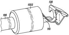
在一个实施例中,安全夹128能够至少部分地驻留或者容纳或者包含在密封构件132的内部腔体178的近侧部分184内,并且至少部分地驻留或者容纳或者包含在导管接口122的内部腔体146的近侧部分148内。在一个实施例中,导管插入组件100还能够包括近侧杯状体1502,安全夹128的近侧部分至少部分地驻留或者容纳或者包含在近侧杯状体1502内。In one embodiment, the
参考图23A,描绘了根据本公开的实施例的近侧杯状体1502。在一个实施例中,近侧杯状体1502能够包括近端1504、开放的远端1506和在其间限定内部腔体的大致圆柱形的壁1508。在一个实施例中,近侧杯状体1502的近端1504能够限定孔口1512,该孔口1512的形状和大小设计成与针头套管106的外径紧密符合,以便在导管组件104前进期间、通过限制空气和/或体液从导管接口122的内部腔体146流出来阻止血液或者体液的泄漏和/或包含来自患者的血液或者体液。在一些实施例中,近侧杯状体1502能够在安全夹128过渡到第二或安全位置之前阻止对安全夹128的破坏(如图23B中所描绘的)。在一些实施例中,因为在过渡到第二或安全位置之前和之后,近侧杯状体1502能够固定地或者可操作地耦接到安全夹128,因此,近侧杯状体1502用于进一步稳定安全夹128。在一个实施例中,近侧杯状体1502能够由金属制成。在一个实施例中,安全夹128和近侧杯状体1502能够形成为整体部件。Referring to FIG. 23A , a
参考图23C,为了在导管组件104的前进期间进一步阻止血液或者体液的泄漏,在一些实施例中,近侧杯状体1502能够进一步包括杆延伸部1514。杆延伸部1514能够包括限定孔口1518的大致圆柱形的壁1516,孔口1518的形状和大小设计成与针头套管106的外径紧密符合,以便阻止血液或者体液的泄漏。在一个实施例中,杆延伸部1514能够由金属制成。在其他实施例中,杆延伸部1514能够由柔性或者回弹性材料形成,以进一步帮助与针头套管106的外径符合。在针头套管106包括凹口120以指示在针头套管106的外径与导管管部124的内径之间的闪回的实施例中,杆延伸部1514的大小能够适当地设计成在凹口120上方延伸,以便阻止血液或者体液流过凹口120。Referring to FIG. 23C , to further prevent leakage of blood or bodily fluids during advancement of the
如图23D中所描绘的,描绘了根据本公开的实施例的包括近侧杯状体1502的安全导管组件100的局部横截面图,其中,安全导管组件处于第一或准备使用位置。在该实施例中,安全夹128的近侧部分至少部分地驻留或者容纳或者包含在近侧杯状体1502内。如图23E中所描绘的,描绘了根据本公开的实施例的处于第二或安全位置的导管插入装置102、近侧杯状体1502和安全夹128的立体图。在该实施例中,安全夹128的近侧部分保持在近侧杯状体1502内。As depicted in FIG. 23D , a partial cross-sectional view of
应当理解,在本教导的方法中使用的各个步骤可以以任何顺序和/或同时执行,只要该教导仍然可操作。此外,应当理解,本教导的设备和方法能够包括所描述的实施例的任何数量或者全部,只要该教导仍然可操作。It should be understood that the various steps used in the methods of the present teachings may be performed in any order and/or simultaneously so long as the teachings remain operable. Furthermore, it should be understood that the apparatus and methods of the present teachings can include any number or all of the described embodiments, so long as the teachings remain operable.
本文已经描述了系统、装置和方法的各种实施例。这些实施例仅通过示例的方式给出,并且不旨在限制要求保护的发明的范围。此外,应当理解,已经描述的实施例的各种特征可以以各种方式组合以产生许多另外的实施例。而且,虽然已经描述了各种材料、尺寸、形状、配置和位置等以用于所公开的实施例,但是在不超出所要求保护的发明范围的情况下,可以利用除了所公开的那些材料、尺寸、形状、配置和位置等之外的其他材料、尺寸、形状、配置和位置等。Various embodiments of systems, devices, and methods have been described herein. These examples are given by way of example only, and are not intended to limit the scope of the claimed invention. Furthermore, it should be appreciated that various features of the described embodiments can be combined in various ways to yield many additional embodiments. Moreover, while various materials, dimensions, shapes, configurations and locations, etc. have been described for use in the disclosed embodiments, materials other than those disclosed, Material, size, shape, configuration and location, etc. other than size, shape, configuration, location, etc.
相关领域的普通技术人员将认识到,本文的主题可以包括比在上述任何单独实施例中所示的更少的特征。本文描述的实施例并不意味着可以组合本文的主题的各种特征的方式的详尽呈现。因此,实施例不是相互排斥的特征组合;而是,如本领域普通技术人员所理解的,各种实施例能够包括选自不同的单独实施例的不同的单独特征的组合。而且,即使当没有在其他实施例中描述时,关于一个实施例描述的元件也能够在这样的实施例中实现,除非另有说明。Those of ordinary skill in the relevant art will recognize that the subject matter herein may include fewer features than shown in any single foregoing embodiment. The embodiments described herein are not meant to be an exhaustive presentation of the ways in which the various features of the subject matter herein may be combined. Accordingly, the embodiments are not mutually exclusive combinations of features; rather, various embodiments can include combinations of different individual features selected from different individual embodiments, as understood by those of ordinary skill in the art. Furthermore, elements described with respect to one embodiment can be implemented in such embodiment even when not described in another embodiment, unless stated otherwise.
尽管从属权利要求可以在权利要求中提及与一个或多个其他权利要求的特定组合,但是其它实施例也能够包括从属权利要求与每个其它从属权利要求的主题的组合或者一个或多个特征与其它从属或独立权利要求的组合。在本文中提出这样的组合,除非声明不想要特定组合。Although dependent claims may mention in a claim a specific combination with one or more other claims, other embodiments can also comprise a combination of the subject matter or one or more features of a dependent claim with each other dependent claim Combinations with other dependent or independent claims. Such combinations are proposed herein unless it is stated that a particular combination is not intended.
通过引用以上文献的任何并入被限制,使得不并入与本文的明确公开相反的主题。通过引入以上文献的任何并入进一步被限制,使得文献中包括的权利要求不通过引用并入本文。通过引用以上文献的任何并入进一步被限制,使得文献中提供的任何限定不通过引用并入本文,除非明确包括在本文中。Any incorporation by reference of documents above is limited such that no subject matter is incorporated that is contrary to the express disclosure herein. Any incorporation by introduction of documents above is further limited such that no claims contained in the documents are incorporated herein by reference. Any incorporation by reference of documents above is further limited such that any limitations provided in the documents are not incorporated herein by reference unless expressly included herein.
出于解释权利要求的目的,明确意图是不援引35U.S.C第112节(f)的规定,除非在权利要求中叙述特定术语“用于......的手段”或“用于......的步骤”。For purposes of claim interpretation, it is expressly intended not to invoke the provisions of 35 U.S.C. Section 112(f) unless the specific term "means for" or "for. .....A step of".
Claims (15)
Translated fromChinesePriority Applications (1)
| Application Number | Priority Date | Filing Date | Title |
|---|---|---|---|
| CN202310816062.9ACN116764072A (en) | 2018-01-31 | 2019-01-31 | Releasable safety catheter insertion assembly |
Applications Claiming Priority (5)
| Application Number | Priority Date | Filing Date | Title |
|---|---|---|---|
| US201862624470P | 2018-01-31 | 2018-01-31 | |
| US62/624,470 | 2018-01-31 | ||
| US201862643229P | 2018-03-15 | 2018-03-15 | |
| US62/643,229 | 2018-03-15 | ||
| PCT/US2019/016017WO2019152630A1 (en) | 2018-01-31 | 2019-01-31 | Releasable safety catheter insertion assembly |
Related Child Applications (1)
| Application Number | Title | Priority Date | Filing Date |
|---|---|---|---|
| CN202310816062.9ADivisionCN116764072A (en) | 2018-01-31 | 2019-01-31 | Releasable safety catheter insertion assembly |
Publications (2)
| Publication Number | Publication Date |
|---|---|
| CN111971084A CN111971084A (en) | 2020-11-20 |
| CN111971084Btrue CN111971084B (en) | 2023-06-06 |
Family
ID=67479850
Family Applications (2)
| Application Number | Title | Priority Date | Filing Date |
|---|---|---|---|
| CN202310816062.9APendingCN116764072A (en) | 2018-01-31 | 2019-01-31 | Releasable safety catheter insertion assembly |
| CN201980023690.3AActiveCN111971084B (en) | 2018-01-31 | 2019-01-31 | Releasable safety catheter insertion assembly |
Family Applications Before (1)
| Application Number | Title | Priority Date | Filing Date |
|---|---|---|---|
| CN202310816062.9APendingCN116764072A (en) | 2018-01-31 | 2019-01-31 | Releasable safety catheter insertion assembly |
Country Status (9)
| Country | Link |
|---|---|
| US (1) | US20210100985A1 (en) |
| EP (1) | EP3746168A4 (en) |
| JP (2) | JP7709280B2 (en) |
| CN (2) | CN116764072A (en) |
| AU (1) | AU2019215010B2 (en) |
| CA (1) | CA3090119A1 (en) |
| MX (1) | MX2020008019A (en) |
| MY (1) | MY208028A (en) |
| WO (1) | WO2019152630A1 (en) |
Families Citing this family (26)
| Publication number | Priority date | Publication date | Assignee | Title |
|---|---|---|---|---|
| ES2975734T3 (en) | 2015-01-29 | 2024-07-12 | Becton Dickinson Co | Integrated Quick Insert Catheter |
| MY208028A (en)* | 2018-01-31 | 2025-04-08 | Icu Medical Inc | Releasable safety catheter insertion assembly |
| WO2019199734A1 (en) | 2018-04-11 | 2019-10-17 | Smiths Medical Asd, Inc. | Spring retract iv catheter |
| US11446467B2 (en) | 2018-09-25 | 2022-09-20 | Smiths Medical Asd, Inc. | Overmolded septum for catheter hub |
| US12083294B2 (en)* | 2019-02-20 | 2024-09-10 | Becton, Dickinson And Company | Coupling between a telescoping needle shield and a catheter adapter |
| US20200316359A1 (en)* | 2019-04-04 | 2020-10-08 | Becton, Dickinson And Company | Multi-use blood control catheter assembly |
| US11344704B2 (en)* | 2019-07-11 | 2022-05-31 | Becton, Dickinson And Company | Catheter system facilitating reduced drag force |
| CA3169051A1 (en) | 2019-09-10 | 2021-03-18 | Medsource International Llc | An intravenous catheter device |
| CN213252024U (en)* | 2019-09-10 | 2021-05-25 | 贝克顿·迪金森公司 | Vascular access system and clamping device |
| BR112022005254A2 (en)* | 2019-09-24 | 2022-06-14 | Bard Access Systems Inc | Acute central venous catheter and peripherally inserted venous catheter integrated |
| US20210187250A1 (en)* | 2019-12-18 | 2021-06-24 | Becton, Dickinson And Company | Inhibiting fluid leakage and splatter in catheter devices and systems |
| CA3168492A1 (en) | 2020-01-23 | 2021-07-29 | Bard Access Systems, Inc. | Splitable catheter docking station system |
| EP4135819A1 (en) | 2020-04-23 | 2023-02-22 | Bard Access Systems, Inc. | Rapidly insertable central catheters including catheter assemblies |
| WO2021236950A1 (en) | 2020-05-21 | 2021-11-25 | Bard Access Systems, Inc. | Rapidly insertable central catheters including catheter assemblies |
| CA3186461A1 (en) | 2020-06-29 | 2022-01-06 | Bard Access Systems, Inc. | Rapidly insertable central catheters including assemblies |
| AU2021303150B2 (en) | 2020-06-29 | 2025-10-02 | Bard Access Systems, Inc. | Rapidly insertable central catheters including catheter assemblies and methods thereof |
| AU2021371314B2 (en) | 2020-10-28 | 2025-09-25 | Bard Access Systems, Inc. | Catheter placement system with stiffening system |
| AU2021400331B2 (en) | 2020-12-17 | 2025-09-25 | Bard Access Systems, Inc. | Rapidly insertable central catheters and assemblies |
| EP4259254A1 (en) | 2020-12-21 | 2023-10-18 | Bard Access Systems, Inc. | Optimized structural support in catheter insertion systems |
| EP4259256A1 (en) | 2020-12-21 | 2023-10-18 | Bard Access Systems, Inc. | Fluid path optimization in catheter insertion systems |
| US12337123B2 (en) | 2021-05-06 | 2025-06-24 | Medsource Labs, Llc | Safety intravenous cannula |
| EP4359053A4 (en)* | 2021-07-30 | 2025-04-23 | Smiths Medical ASD, Inc. | Catheter assembly with needle tip protection and passive blood control |
| JP2024528047A (en)* | 2021-07-30 | 2024-07-26 | スミス メディカル エーエスディー インコーポレーテッド | Safe Catheter Assembly |
| JP2024527091A (en)* | 2021-07-30 | 2024-07-19 | スミス メディカル エーエスディー インコーポレーテッド | Safe Catheter Assembly with Passive Blood Control |
| US12186497B2 (en) | 2022-01-14 | 2025-01-07 | Medsource International Llc | Intravenous cannula |
| WO2025018230A1 (en)* | 2023-07-20 | 2025-01-23 | ニプロ株式会社 | Needle tip protector |
Citations (3)
| Publication number | Priority date | Publication date | Assignee | Title |
|---|---|---|---|---|
| CA2723732A1 (en)* | 2008-05-12 | 2009-11-19 | Becton, Dickinson And Company | Sleeved clip safety |
| CN105396212A (en)* | 2014-04-29 | 2016-03-16 | B.布劳恩梅尔松根股份公司 | Valved Catheter Assemblies And Related Methods |
| CN106488781A (en)* | 2014-04-18 | 2017-03-08 | 贝克顿·迪金森公司 | Multipurpose Blood Control Safety Catheter Assembly |
Family Cites Families (18)
| Publication number | Priority date | Publication date | Assignee | Title |
|---|---|---|---|---|
| US6616630B1 (en) | 1997-08-20 | 2003-09-09 | B. Braun Melsungen A.G. | Spring clip safety IV catheter |
| US6117108A (en) | 1997-08-20 | 2000-09-12 | Braun Melsungen Ag | Spring clip safety IV catheter |
| JP2002085558A (en) | 2000-09-19 | 2002-03-26 | Terumo Corp | Puncture tool and retention needle assembly |
| US7179244B2 (en)* | 2001-03-15 | 2007-02-20 | Specialized Health Products, Inc. | Resettable safety shield for medical needles |
| US7798994B2 (en)* | 2005-11-15 | 2010-09-21 | Becton, Dickinson And Company | Needle shield to septum interconnect |
| US8652104B2 (en)* | 2010-06-25 | 2014-02-18 | Smiths Medical Asd, Inc. | Catheter assembly with seal member |
| US9545495B2 (en)* | 2010-06-25 | 2017-01-17 | Smiths Medical Asd, Inc. | Catheter assembly with seal member |
| JP5880983B2 (en)* | 2011-08-23 | 2016-03-09 | ニプロ株式会社 | Indwelling needle assembly |
| US9623210B2 (en)* | 2013-03-15 | 2017-04-18 | B. Braun Melsungen Ag | Catheter assemblies with wipeable bloodstop and related methods |
| US9114231B2 (en)* | 2013-03-15 | 2015-08-25 | B. Braun Melsungen Ag | Valved catheter assemblies and related methods |
| CN203694357U (en)* | 2013-03-15 | 2014-07-09 | B.布劳恩梅尔松根股份公司 | safety IV catheter |
| US10500376B2 (en)* | 2013-06-07 | 2019-12-10 | Becton, Dickinson And Company | IV catheter having external needle shield and internal blood control septum |
| GB2508570C2 (en)* | 2013-08-21 | 2025-07-30 | Braun Melsungen Ag | Catheter assembly |
| US10918837B2 (en)* | 2013-12-04 | 2021-02-16 | B. Braun Melsungen Ag | Safety needle assemblies and related methods |
| EP3552652B2 (en)* | 2015-08-18 | 2024-07-03 | B. Braun Melsungen AG | Catheter devices with valves |
| US20170119977A1 (en)* | 2015-10-30 | 2017-05-04 | B. Braun Melsungen Ag | Valved catheters and related methods |
| WO2017151052A1 (en)* | 2016-03-04 | 2017-09-08 | Vigmed Ab | Blood collection device |
| MY208028A (en)* | 2018-01-31 | 2025-04-08 | Icu Medical Inc | Releasable safety catheter insertion assembly |
- 2019
- 2019-01-31MYMYPI2020003871Apatent/MY208028A/enunknown
- 2019-01-31MXMX2020008019Apatent/MX2020008019A/enunknown
- 2019-01-31CNCN202310816062.9Apatent/CN116764072A/enactivePending
- 2019-01-31WOPCT/US2019/016017patent/WO2019152630A1/ennot_activeCeased
- 2019-01-31JPJP2020541899Apatent/JP7709280B2/enactiveActive
- 2019-01-31USUS15/733,439patent/US20210100985A1/enactivePending
- 2019-01-31EPEP19746613.9Apatent/EP3746168A4/enactivePending
- 2019-01-31AUAU2019215010Apatent/AU2019215010B2/enactiveActive
- 2019-01-31CNCN201980023690.3Apatent/CN111971084B/enactiveActive
- 2019-01-31CACA3090119Apatent/CA3090119A1/enactivePending
- 2023
- 2023-07-31JPJP2023124151Apatent/JP7685017B2/enactiveActive
Patent Citations (4)
| Publication number | Priority date | Publication date | Assignee | Title |
|---|---|---|---|---|
| CA2723732A1 (en)* | 2008-05-12 | 2009-11-19 | Becton, Dickinson And Company | Sleeved clip safety |
| EP2282799A1 (en)* | 2008-05-12 | 2011-02-16 | Becton, Dickinson and Company | Sleeved clip safety |
| CN106488781A (en)* | 2014-04-18 | 2017-03-08 | 贝克顿·迪金森公司 | Multipurpose Blood Control Safety Catheter Assembly |
| CN105396212A (en)* | 2014-04-29 | 2016-03-16 | B.布劳恩梅尔松根股份公司 | Valved Catheter Assemblies And Related Methods |
Also Published As
| Publication number | Publication date |
|---|---|
| AU2019215010A1 (en) | 2020-09-03 |
| EP3746168A4 (en) | 2022-03-02 |
| WO2019152630A1 (en) | 2019-08-08 |
| EP3746168A1 (en) | 2020-12-09 |
| JP2021511890A (en) | 2021-05-13 |
| MX2020008019A (en) | 2020-12-03 |
| JP7685017B2 (en) | 2025-05-28 |
| JP7709280B2 (en) | 2025-07-16 |
| CN116764072A (en) | 2023-09-19 |
| JP2023133444A (en) | 2023-09-22 |
| AU2019215010B2 (en) | 2024-02-22 |
| CA3090119A1 (en) | 2019-08-08 |
| US20210100985A1 (en) | 2021-04-08 |
| CN111971084A (en) | 2020-11-20 |
| MY208028A (en) | 2025-04-08 |
Similar Documents
| Publication | Publication Date | Title |
|---|---|---|
| CN111971084B (en) | Releasable safety catheter insertion assembly | |
| US12150765B2 (en) | Releaseable catheter hub retainer | |
| US11260204B2 (en) | Spring retract IV catheter | |
| AU2021206876B2 (en) | Closed system catheter | |
| US10548522B2 (en) | Releaseable catheter hub retainer | |
| CN111032136B (en) | Method and device for accessing a blood vessel | |
| US20230347112A1 (en) | Iv catheter with a tip protector | |
| CN104540538B (en) | Trocar IV catheter assembly with integrated IV tubing | |
| WO2019079719A1 (en) | Catheter with threading flash confirmation |
Legal Events
| Date | Code | Title | Description |
|---|---|---|---|
| PB01 | Publication | ||
| PB01 | Publication | ||
| SE01 | Entry into force of request for substantive examination | ||
| SE01 | Entry into force of request for substantive examination | ||
| GR01 | Patent grant | ||
| GR01 | Patent grant | ||
| TR01 | Transfer of patent right | ||
| TR01 | Transfer of patent right | Effective date of registration:20250326 Address after:California, USA Patentee after:ICU Medical, Inc. Country or region after:U.S.A. Address before:American Minnesota Patentee before:SMITHS MEDICAL ASD, Inc. Country or region before:U.S.A. |