CN111970990B - Releasable palatal expander - Google Patents
Releasable palatal expanderDownload PDFInfo
- Publication number
- CN111970990B CN111970990BCN201980025289.3ACN201980025289ACN111970990BCN 111970990 BCN111970990 BCN 111970990BCN 201980025289 ACN201980025289 ACN 201980025289ACN 111970990 BCN111970990 BCN 111970990B
- Authority
- CN
- China
- Prior art keywords
- palatal
- region
- patient
- teeth
- palate
- Prior art date
- Legal status (The legal status is an assumption and is not a legal conclusion. Google has not performed a legal analysis and makes no representation as to the accuracy of the status listed.)
- Active
Links
Images


Classifications
- A—HUMAN NECESSITIES
- A61—MEDICAL OR VETERINARY SCIENCE; HYGIENE
- A61C—DENTISTRY; APPARATUS OR METHODS FOR ORAL OR DENTAL HYGIENE
- A61C7/00—Orthodontics, i.e. obtaining or maintaining the desired position of teeth, e.g. by straightening, evening, regulating, separating, or by correcting malocclusions
- A61C7/10—Devices having means to apply outwardly directed force, e.g. expanders
- A—HUMAN NECESSITIES
- A61—MEDICAL OR VETERINARY SCIENCE; HYGIENE
- A61C—DENTISTRY; APPARATUS OR METHODS FOR ORAL OR DENTAL HYGIENE
- A61C7/00—Orthodontics, i.e. obtaining or maintaining the desired position of teeth, e.g. by straightening, evening, regulating, separating, or by correcting malocclusions
- A61C7/002—Orthodontic computer assisted systems
- A—HUMAN NECESSITIES
- A61—MEDICAL OR VETERINARY SCIENCE; HYGIENE
- A61C—DENTISTRY; APPARATUS OR METHODS FOR ORAL OR DENTAL HYGIENE
- A61C7/00—Orthodontics, i.e. obtaining or maintaining the desired position of teeth, e.g. by straightening, evening, regulating, separating, or by correcting malocclusions
- A61C7/02—Tools for manipulating or working with an orthodontic appliance
- A61C7/023—Tools for manipulating or working with an orthodontic appliance for debonding or removing orthodontic devices
- A—HUMAN NECESSITIES
- A61—MEDICAL OR VETERINARY SCIENCE; HYGIENE
- A61C—DENTISTRY; APPARATUS OR METHODS FOR ORAL OR DENTAL HYGIENE
- A61C7/00—Orthodontics, i.e. obtaining or maintaining the desired position of teeth, e.g. by straightening, evening, regulating, separating, or by correcting malocclusions
- A61C7/08—Mouthpiece-type retainers or positioners, e.g. for both the lower and upper arch
Landscapes
- Health & Medical Sciences (AREA)
- Oral & Maxillofacial Surgery (AREA)
- Dentistry (AREA)
- Epidemiology (AREA)
- Life Sciences & Earth Sciences (AREA)
- Animal Behavior & Ethology (AREA)
- General Health & Medical Sciences (AREA)
- Public Health (AREA)
- Veterinary Medicine (AREA)
- Engineering & Computer Science (AREA)
- General Engineering & Computer Science (AREA)
- Dental Tools And Instruments Or Auxiliary Dental Instruments (AREA)
Abstract
Translated fromChinese
Description
Translated fromChinese相关申请related application
本专利申请要求2018年4月11日提交的题为“RELEASABLE PALATAL EXPANDERS(可释放的腭扩张器)”的美国临时专利申请No.62/656,289以及2018年9月24日提交的题为“RELEASABLE PALATAL EXPANDERS(可释放的腭扩张器)”的美国临时专利申请No.62/735,658的优先权,上述申请各自的全部内容通过引用并入本文。This application for patent claims U.S. Provisional Patent Application No. 62/656,289, filed April 11, 2018, entitled "RELEASABLE PALATAL EXPANDERS," and U.S. Provisional Patent Application No. 62/656,289, filed September 24, 2018, entitled "RELEASABLE PALATAL EXPANDERS (releasable palatal expanders)" U.S. Provisional Patent Application No. 62/735,658, the entire contents of each of which are incorporated herein by reference.
本专利申请还可与2017年12月4日提交的美国专利申请15/831,159(题为“PALATAL EXPANDERS AND METHODS OF EXPANDING A PALATE(腭扩张器和扩张腭的方法)”)有关,该美国专利申请要求2016年12月2日提交的美国临时专利申请No.62/429,692(题为“METHODS OF FABRICATING PALATAL EXPANDERS(腭扩张器的制造方法)”)以及2017年8月8日提交的美国临时专利申请No.62/542,750(题为“PALATAL EXPANDERS ANDMETHODS OF EXPANDING A PALATE(腭扩张器和扩张腭的方法)”)的优先权,上述申请各自的全部内容通过引用并入本文。This patent application is also related to U.S. Patent Application 15/831,159, filed December 4, 2017, entitled "PALATAL EXPANDERS AND METHODS OF EXPANDING A PALATE," which Requests for U.S. Provisional Patent Application No. 62/429,692, filed December 2, 2016, entitled "METHODS OF FABRICATING PALATAL EXPANDERS" and U.S. Provisional Patent Application filed August 8, 2017 Priority to No. 62/542,750, entitled "PALATAL EXPANDERS ANDMETHODS OF EXPANDING A PALATE," each of which is incorporated herein by reference in its entirety.
本申请可与美国专利申请公开No.2016/0081768(题为“ARCH EXPANDINGAPPLIANCE(牙弓扩张器具)”)和美国专利申请公开No.2016/0081769(题为“ARCHADJUSTMENT APPLIANCE(牙弓调节器具)”)有关,上述申请各自的全部内容通过引用并入本文。This application may be compared with U.S. Patent Application Publication No. 2016/0081768 (entitled "ARCH EXPANDING APPLIANCE (Dental Arch Expansion Appliance)") and U.S. Patent Application Publication No. 2016/0081769 (entitled "ARCHADJUSTMENT APPLIANCE (Dental Arch Adjustment Appliance)" ), each of which is hereby incorporated by reference in its entirety.
援引并入Incorporate by reference
本说明书中提及的所有出版物和专利申请均通过引用整体并入本文,其程度如同每个单独的出版物或专利申请被具体和单独地指示为通过引用并入。All publications and patent applications mentioned in this specification are herein incorporated by reference in their entirety to the same extent as if each individual publication or patent application was specifically and individually indicated to be incorporated by reference.
技术领域technical field
本技术领域涉及可移除的腭扩张器、制造腭扩张器的方法以及使用和/或移除腭扩张器的方法。The technical field relates to removable palate dilators, methods of making palate dilators, and methods of using and/or removing palate dilators.
背景技术Background technique
各种正畸问题与狭窄的腭相关。在一些情况下,患者的上颌骨尺寸不足以容纳患者的上牙。在其他情况下,存在用于上牙的空间,但是腭太狭窄以致发音受损或变得困难。在其他情况下,腭太高以至于减少了可以通过鼻子的空气量,因此在不打开口腔的情况下几乎不可能进行深呼吸。在所有这些情况下,腭扩张(包括施加力以分离、扩宽(widen)和/或扩展(spread)上颌骨)可能是有帮助的。Various orthodontic problems are associated with a narrow palate. In some instances, the patient's maxilla is insufficiently sized to accommodate the patient's upper teeth. In other cases, there is room for the upper teeth, but the palate is so narrow that pronunciation is impaired or difficult. In other cases, the palate is so high that it reduces the amount of air that can pass through the nose, making it nearly impossible to take a deep breath without opening the mouth. In all of these cases, palatal expansion (including applying force to separate, widen, and/or spread the maxilla) may be helpful.
虽然存在许多传统的腭扩张器用于使患者的上颌骨分离、扩宽、扩展等,但这些器具往往很难移除。例如,许多腭扩张器在插入患者的腭中时,会在患者的腭和/或牙弓上施加很大的力。由于这些和其他因素,通常很难从患者的口腔移除腭扩张器。这些问题可能对成人患者持续存在,但对于儿童患者、与普通成人患者相比协调性较差的患者、或由监护人(如父母)移除腭扩张器的患者来说也是存在的。此外,在患者牙冠上形成附件的传统技术利用热成型的附件模板,并且可能在能形成的几何形状上受限。While many traditional palatal expanders exist for separating, widening, extending, etc. a patient's maxilla, these devices are often difficult to remove. For example, many palatal expanders exert significant force on the patient's palate and/or dental arch when inserted into the patient's palate. Because of these and other factors, it is often difficult to remove the palatal expander from the patient's mouth. These problems may persist in adult patients, but are also present in pediatric patients, patients who have poorer coordination than the average adult patient, or patients who have had palatal expanders removed by a guardian (eg, parent). Furthermore, conventional techniques for forming appendages on patient crowns utilize thermoformed appendage templates and may be limited in the geometries that can be formed.
发明内容Contents of the invention
本文描述的是能够容易地从患者口腔中移除的腭扩张器设备(包括装置和系统)。本文还描述了能够用于从患者口腔中移除腭扩张器的移除工具。本文描述的系统和技术使得即使当腭扩张器附接到患者牙齿和/或腭上的一个或多个附件时,也能够容易地从患者的腭移除(例如,拆卸)腭扩张器。本文描述的实施例可以包括腭扩张器(和/或腭扩张器的系列),所述腭扩张器包括破坏区域。本文中使用的“破坏区域”可以是指结构的一个区域,该区域被构造成通过破坏区域的材料、几何形状、位置和/或其他特性帮助结构的断裂、弯曲、变形等。在一些实施例中,破坏区域可以包括一区域,其材料与用于形成腭扩张器其余部分的材料不同。用于形成破坏区域的材料可以更软、更脆,或者与用于形成腭扩张器其余部分的材料完全不同,使得腭扩张器可以在破坏区域处断裂、弯曲、变形等。在一些实施例中,破坏区域可以具有与腭扩张器的其他区域不同的轮廓或几何形状,使得腭扩张器可以在破坏区域处断裂、弯曲、变形等。Described herein are palate dilator devices (including devices and systems) that can be easily removed from a patient's mouth. Also described herein is a removal tool that can be used to remove a palatal expander from a patient's mouth. The systems and techniques described herein enable easy removal (eg, detachment) of the palate expander from the patient's palate even when the palate expander is attached to the patient's teeth and/or one or more appendages on the palate. Embodiments described herein may include a palate dilator (and/or series of palate dilators) that includes a disrupted region. As used herein, a "failure region" may refer to a region of a structure configured to facilitate fracture, bending, deformation, etc. of the structure through the material, geometry, location, and/or other characteristics of the failure region. In some embodiments, the disrupted region may comprise a region of a different material than the material used to form the rest of the palatal dilator. The material used to form the damage area can be softer, more brittle, or completely different than the material used to form the rest of the palatal expander, so that the palate expander can break, bend, deform, etc. at the damage area. In some embodiments, the disrupted region may have a different profile or geometry than other regions of the palatal expander such that the palatal expander may break, bend, deform, etc. at the disrupted region.
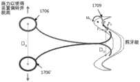
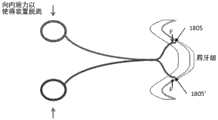
破坏区域可以策略性地放置在腭扩张器的用于吸收置于腭扩张器上的移除力的位置处。作为示例,破坏区域可以策略性地放置在支点的另一侧上,所述支点形成在破坏区域和扩张器的边缘之间,用于从腭移除腭扩张器。破坏区域可以比腭扩张器的其他区域更有效地吸收通过移除力产生的移除能量。破坏区域的断裂、弯曲、变形等可能会产生足够的力,以将腭扩张器从患者的腭移除。如本文进一步指出的,腭扩张器的侧面或边缘可具有一个或多个脱离区域,所述脱离区域可包括与一个或多个扩张器移除工具(包括手指、带钩的工具和/或其他结构)对接的一个或多个边缘几何形状。边缘几何形状可以有助于通过支点和/或其他结构将移除力传递到破坏区域。在一些实施例中,边缘几何形状位于任一牙齿接合区域的颊侧。移除力可以(但不必)包括“拉力”,所述拉力是在远离患者牙列的方向上移动的力。在一些实施例中,力可导致破坏区域“可预见地”弯曲、断裂、变形等,或根据基本上可预见的方式和/或以基本上可预见的布置而断裂。The breach zone can be strategically placed at the location of the palatal expander to absorb the removal force placed on the palatal expander. As an example, the breaching region may be strategically placed on the other side of the fulcrum formed between the breaching region and the edge of the dilator for removing the palatal dilator from the palate. The disrupted region can absorb the removal energy generated by the removal force more effectively than other regions of the palatal dilator. Breakage, bending, deformation, etc. of the disrupted area may generate sufficient force to remove the palatal expander from the patient's palate. As further noted herein, the sides or edges of the palatal dilator may have one or more disengagement areas that may include contact with one or more dilator removal tools (including fingers, hooked tools, and/or other structure) one or more edge geometries for butt joints. Edge geometry can help transfer removal forces to the failure zone through fulcrums and/or other structures. In some embodiments, the edge geometry is on the buccal side of either tooth-engaging area. Removal forces may, but need not, include "pull forces," which are forces that move in a direction away from the patient's dentition. In some embodiments, the force may cause the failure region to "predictably" bend, break, deform, etc., or break in a substantially predictable manner and/or in a substantially predictable arrangement.
本发明公开了具有破坏区域的腭扩张器的移除方法。本文还公开了具有破坏区域的腭扩张器的设计和/或制造方法。The present invention discloses a method of removing a palatal dilator having a disrupted region. Also disclosed herein are methods of designing and/or manufacturing palatal dilators having disrupted regions.
在一些实施例中,设备(诸如装置和系统)用于使用一系列腭扩张器对患者的腭进行逐步扩张。本文提供用于逐步腭扩张的方法和设备(包括系统和装置)。这些腭扩张器可适用于舒适、有效和/或容易的移除。例如,本文描述了用于腭扩张的系统,其可包括一系列增量扩张器,这一系列增量扩张器包括:第一增量扩张器,所述第一增量扩张器具有被选择为扩张腭的几何形状;和一个或多个中间扩张器,所述一个或多个中间扩张器具有被选择为逐步将腭扩张到目标期望宽度的几何形状。In some embodiments, devices, such as devices and systems, are used to progressively expand a patient's palate using a series of palate dilators. Provided herein are methods and devices, including systems and devices, for gradual palatal expansion. These palatal dilators may be adapted for comfortable, effective and/or easy removal. For example, a system for palatal expansion is described herein that may include a series of incremental dilators including a first incremental dilator having a function selected to be the geometry of the expanded palate; and one or more intermediate dilators having a geometry selected to progressively expand the palate to a target desired width.
通常,腭扩张器已经被描述为预成形装置,其具有:第一臼齿接合(或臼齿/前臼齿接合)区域,适于在上颌的第一侧上接合上臼齿;第二臼齿接合(或臼齿/前臼齿接合)区域,适于在上颌的第二侧上接合上臼齿;以及腭区域,腭区域的几何形状被配置为与腭的形状相邻适配,同时提供侧向力以使腭逐步扩张。为了方便起见,腭扩张器可以简单地称为“扩张器”或“腭扩张器设备”。一系列扩张器中的每个腭扩张器可以包括两个臼齿区域(其也可以被构造为包括前臼齿),每侧一个,每个臼齿区域具有一个或多个腔,每个腔适于装配在患者的一个臼齿(或臼齿和/或前臼齿)上。在一个实施例中,每个臼齿区域可以包括两个(或更多个)腔,所述腔被构造成装配在两个(或更多个)后臼齿或前臼齿上。每个腭扩张器可以包括一个腭区域,该腭区域将两个臼齿区域分开并抵靠患者的腭装配。通常,所述扩张器系列中的臼齿区域之间的距离按照其将被佩戴的顺序依次增大。In general, palatal expanders have been described as preformed devices having: a first molar occlusal (or molar/premolar occlusal) region adapted to engage upper molars on a first side of the upper jaw; /premolar occlusion) region adapted to engage the upper molars on the second side of the upper jaw; and the palatal region, the geometry of which is configured to fit adjacent to the shape of the palate while providing lateral force to allow the palate to progressively expansion. For convenience, palatal dilators may be referred to simply as "dilators" or "palatal dilator devices." Each palatal expander in the series of expanders may include two molar regions (which may also be configured to include premolars), one on each side, each molar region having one or more cavities, each cavity adapted to fit On one of the patient's molars (or molars and/or premolars). In one embodiment, each molar region may include two (or more) cavities configured to fit over two (or more) rear molars or premolars. Each palatal expander may include a palatal region that separates two molar regions and fits against the patient's palate. Typically, the distance between the molar regions in the series of expanders increases sequentially in the order in which they will be worn.
装置的腭区域可以提供力以拉伸或扩张中腭区域。尽管在该区域可放置能量增强特征件(例如,弹簧和热活性材料),该区域还可以包括一个或多个适配件,例如支杆(struts)、支撑件、横梁、肋、间隙/窗口、附件等,它可以以比先前描述的更细微的方式分配所施加的力。例如,这些装置可以被构造为,通过在腭扩张器与患者口腔(例如,在牙龈中和/或优选地沿着患者牙齿的上部或下部侧向部分,包括其臼齿)之间布置一个或多个接触点,使得所施加的力以预定和/或期望的模式分布。还可以调节装置的曲率(例如,凹度),以分配所施加的力,同时允许腭与装置之间的空隙,和/或允许用于使用者舌头的空隙。The palatal region of the device may provide force to stretch or expand the mid-palatal region. Although energy enhancing features (e.g. springs and thermally active materials) may be placed in this area, this area may also include one or more fittings such as struts, supports, beams, ribs, gaps/windows , attachments, etc., which can distribute the applied force in a more subtle manner than previously described. For example, these devices may be configured by placing one or more jaws between the palatal expander and the patient's mouth (e.g., in the gums and/or preferably along the upper or lower lateral portions of the patient's teeth, including their molars). points of contact such that the applied force is distributed in a predetermined and/or desired pattern. The curvature (eg, concavity) of the device can also be adjusted to distribute the applied force while allowing clearance between the palate and the device, and/or allowing clearance for the user's tongue.
本文描述的用于扩张患者的腭的任何腭扩张器设备(例如,装置、系统等)可包括一个或多个锁。锁可以通过将腭扩张器的颊侧锁定到结合到牙齿的一个或多个附件来将腭扩张器固定到患者的牙齿,从而允许来自腭扩张器的侧向力对适当区域中的上腭施加适当扩张力。锁可被手动解锁,例如,通过致动控制器(例如,凸片等)或以其他方式施加释放力来使锁脱开(disengage)。可以使用多个锁,并且可以操作以保持侧向力来防止腭扩张器脱开,直到锁被解锁为止。Any of the palate dilator devices (eg, devices, systems, etc.) described herein for dilating a patient's palate may include one or more locks. The lock may secure the palatal expander to the patient's teeth by locking the buccal side of the palatal expander to one or more attachments bonded to the teeth, allowing lateral force from the palatal expander to be applied to the palate in the appropriate area Appropriate expansion force. The lock may be manually unlocked, for example, by actuating a control (eg, a tab, etc.) or otherwise applying a release force to disengage the lock. Multiple locks may be used and may operate to maintain a lateral force to prevent disengagement of the palatal dilator until the lock is unlocked.
例如,腭扩张器(例如,腭扩张器系统)可以包括:腭扩张器,其具有第一牙齿接合区域、第二牙齿接合区域和腭区域,所述腭区域连接所述第一和第二牙齿接合区域并且被构造成在所述第一牙齿接合区域和所述第二牙齿接合区域之间施加侧向力;位于第一牙齿接合区域和第二牙齿接合区域的颊侧上的多个附件联接区域;多个锁,其中所述多个附件联接区域中的每个附件联接区域与所述多个锁中的一锁关联,进一步地其中每个锁被构造成与附件联接区域内的附件接合以将腭扩张器锁定到患者的牙齿上。For example, a palate expander (e.g., a palate expander system) can include a palate expander having a first tooth engaging region, a second tooth engaging region, and a palatal region connecting the first and second teeth an engagement region and configured to apply a lateral force between the first tooth engagement region and the second tooth engagement region; a plurality of attachment couplings located on the buccal side of the first tooth engagement region and the second tooth engagement region A region; a plurality of locks, wherein each accessory coupling region of the plurality of accessory coupling regions is associated with a lock of the plurality of locks, further wherein each lock is configured to engage an accessory within the accessory coupling region to lock the palatal expander to the patient's teeth.
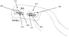
附件联接区域可以是进入或穿过腭扩张器的凹槽、开口等,用于与结合到牙齿的一个或多个附件接合。例如,附件联接区域可以是穿过腭扩张器的颊侧的窗口(例如,附件窗口)。The accessory coupling region may be a groove, opening, etc. into or through the palatal expander for engagement with one or more accessories bonded to the teeth. For example, the appendage coupling region may be a window through the buccal side of the palatal dilator (eg, the appendage window).
锁通常可以包括与支柱(stay)接合的释放控制器。释放控制器可以位于腭扩张器上,支柱可以位于附件上,或者,支柱可以物腭扩张器上,而释放控制器可以位于附件上。例如,锁可以包括释放控制器,所述释放控制器包括闩锁、杠杆、开关、钩、凸片、臂、卡扣、杆、销等,所述释放控制器通过附件联接区域与支柱(例如,通道、中空部(hollow)、止回件、夹板、卡子(catch)、钩扣、搭钩(hasp,搭扣)、突起等)接合。The lock may typically include a release control that engages the stay. The release control can be on the palatal dilator and the strut can be on the appendage, or the strut can be on the palatal dilator and the release control can be on the appendage. For example, a lock may include a release control including a latch, lever, switch, hook, tab, arm, catch, lever, pin, etc. that communicates with a post (e.g., , Channels, hollows (hollow), non-return members, splints, clips (catch), hooks, snaps (hasp, buckle), protrusions, etc.) engagement.
例如,用于扩张患者的腭的腭扩张器系统可以包括:腭扩张器,其包括第一牙齿接合区域、第二牙齿接合区域和腭区域,所述腭区域连接所述第一牙齿接合区域和第二牙齿接合区域并且被构造成在第一牙齿接合区域和第二牙齿接合区域之间施加侧向力;位于第一牙齿接合区域的颊侧上的第一附件联接区域;位于第一牙齿接合区域的颊侧上的第一锁,其中,所述第一锁包括第一释放控制器,所述第一释放控制器被构造成延伸到所述第一附件联接区域中,以与第一附件联接区域内的第一附件上的支柱接合,从而将所述腭扩张器锁定到患者的牙齿上,直到所述第一锁被释放;位于所述第二牙齿接合区域的颊侧上的第二附件联接区域;以及位于所述第二牙齿接合区域的颊侧上的第二锁,其中,所述第二锁包括第二释放控制器,所述第二释放控制器被构造成延伸到所述第二附件联接区域中,以与第二附件联接区域内的第二附件上的支柱接合,从而将所述腭扩张器锁定到患者的牙齿上。腭扩张器系统还可以包括附件,例如,第一附件和第二附件,其中第一附件和第二附件被构造成结合到患者的牙齿。For example, a palate expander system for expanding a patient's palate may include a palate expander comprising a first tooth-engaging region, a second tooth-engaging region, and a palatal region connecting the first tooth-engaging region and the palatal region. The second tooth engagement area and configured to apply a lateral force between the first tooth engagement area and the second tooth engagement area; the first accessory coupling area on the buccal side of the first tooth engagement area; A first lock on the buccal side of the region, wherein the first lock includes a first release control configured to extend into the first accessory coupling region to engage with the first accessory The struts on the first attachment in the coupling area engage, thereby locking the palatal expander to the patient's teeth until the first lock is released; the second attachment on the buccal side of the second tooth engagement area an accessory coupling region; and a second lock on the buccal side of the second tooth-engaging region, wherein the second lock includes a second release control configured to extend to the The second accessory coupling region to engage with a post on the second accessory in the second accessory coupling region to lock the palatal expander to the patient's teeth. The palatal expander system can also include attachments, eg, a first attachment and a second attachment, wherein the first attachment and the second attachment are configured to couple to the patient's teeth.
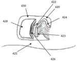
在第一附件和第二附件中的每个上的支柱可以包括通道、中空部、止回件、夹板、卡子、钩扣和搭钩中的一个或多个。第一和第二释放控制器可各自包括闩锁、杠杆、开关、凸片、钩、臂、卡扣、叉齿(prong)、杆和销中的一个或多个。例如,第一释放控制器可以包括闩锁,所述闩锁被构造成滑动到第一附件的支柱内的通道中。在一些示例中,第一释放控制器包括钩,所述钩被构造成与第一附件的支柱接合。在这些示例中的任何一个中,第一释放控制器可以包括一个或多个柔性突起。第一释放控制器可以包括锁定配置和解锁配置,在所述锁定配置中,第一释放控制器延伸到第一附件联接区域中,在所述解锁配置中,第一释放控制器从第一附件联接区域缩回。The struts on each of the first and second attachments may include one or more of channels, hollows, backstops, cleats, clips, clasps, and snaps. The first and second release controls may each include one or more of a latch, lever, switch, tab, hook, arm, snap, prong, lever, and pin. For example, the first release control may include a latch configured to slide into a channel within the post of the first accessory. In some examples, the first release control includes a hook configured to engage the post of the first accessory. In any of these examples, the first release control can include one or more flexible protrusions. The first release control may include a locked configuration in which the first release control extends into the first accessory attachment region and an unlocked configuration in which the first release control extends from the first accessory The joint area is retracted.
第一锁和第二锁可以关于穿过腭扩张器的中线对称地布置在该腭扩张器上,其中该腭扩张器关于所述中线对称。The first lock and the second lock may be symmetrically disposed on the palatal dilator about a midline passing through the palatal dilator, wherein the palatal dilator is symmetrical about said midline.
一种用于扩张患者的腭的腭扩张器系统可以包括腭扩张器,所述腭扩张器包括:第一牙齿接合区域、第二牙齿接合区域和腭区域,所述腭区域连接所述第一牙齿接合区域和第二牙齿接合区域且被构造成在所述第一牙齿接合区域和所述第二牙齿接合区域之间施加侧向力;位于第一牙齿接合区域和第二牙齿接合区域的颊侧上的多个附件联接区域;位于第一牙齿接合区域和第二牙齿接合区域的颊侧上的多个锁,其中每个锁包括释放控制器,所述释放控制器具有锁定配置和解锁配置,在所述锁定配置中,释放控制器延伸到所述多个附件联接区域中的一附件联接区域中,在所述解锁配置中,释放控制器从该附件联接区域缩回;以及多个附件,其中所述多个附件中的每个附件包括支柱,所述支柱被构造成与处于锁定配置的释放控制器接合,从而将腭扩张器锁定到患者的牙齿上。A palate expander system for expanding a palate of a patient may include a palate expander comprising a first tooth engaging region, a second tooth engaging region and a palatal region connecting the first a tooth engagement area and a second tooth engagement area configured to apply a lateral force between said first tooth engagement area and said second tooth engagement area; a plurality of attachment attachment areas on one side; a plurality of locks on the buccal side of the first tooth engagement area and the second tooth engagement area, wherein each lock includes a release control having a locked configuration and an unlocked configuration , in the locked configuration, the release control extends into an accessory coupling area of the plurality of accessory coupling areas, and in the unlocked configuration, the release control is retracted from the accessory coupling area; and a plurality of accessories , wherein each of the plurality of attachments includes a post configured to engage the release controller in a locked configuration to lock the palatal expander to the patient's teeth.
如本文所述的一系列腭扩张器可被构造为通过预定距离(例如,一个扩张器的臼齿区域之间的距离与前一扩张器的臼齿区域之间的距离相差可不超过2mm、在0.1mm和2mm之间、在0.25mm和1mm之间等)和/或通过预定的力(例如,将所施加的力限制为小于180牛顿(N)、在8-200N之间、在8-90N之间、在8-80N之间、在8-70N之间、在8-60N之间、在8-50N之间、在8-40N之间、在8-30N之间、在30-60N之间、在30-70N之间、在40-60N之间、在40-70N之间、在60-200N之间、在70-180N之间、在70-160N之间等,包括在其间的任何范围)使患者的腭扩张。A series of palatal expanders as described herein may be configured to pass a predetermined distance (e.g., the distance between the molar regions of one expander may differ from the distance between the molar regions of the previous expander by no more than 2 mm, within 0.1 mm). and 2mm, between 0.25mm and 1mm, etc.) and/or by a predetermined force (for example, limiting the applied force to less than 180 Newtons (N), between 8-200N, between 8-90N Between, between 8-80N, between 8-70N, between 8-60N, between 8-50N, between 8-40N, between 8-30N, between 30-60N , between 30-70N, between 40-60N, between 40-70N, between 60-200N, between 70-180N, between 70-160N, etc., including any range in between ) to dilate the patient's palate.
在本文描述的任何设备(及其制造方法)中,所述扩张器可由聚合物(例如丙烯酸、热塑性塑料、热固性材料等)和/或金属材料(包括不锈钢、镍钛、铜镍钛等)形成。这些设备中的任一个都可以通过3D打印和/或通过层压工艺形成,其中所述设备由材料层形成,所述材料层可以形成和/或粘附在一起(例如,以形成一个单体装置);不同的层可以具有不同的机械和/或化学性质,并且可以包括不同的厚度或厚度区域。例如,设备可以包括结合在一起的层压材料。In any of the devices described herein (and methods of making them), the dilator may be formed from a polymer (e.g., acrylic, thermoplastic, thermoset, etc.) and/or metallic material (including stainless steel, nickel-titanium, copper-nickel-titanium, etc.) . Any of these devices can be formed by 3D printing and/or by lamination processes, where the device is formed from layers of material that can be formed and/or adhered together (e.g., to form a single device); different layers may have different mechanical and/or chemical properties and may comprise different thicknesses or regions of thickness. For example, a device may comprise laminate materials bonded together.
本文还描述了设备以及通过直接制造技术形成这些设备的方法。例如,可以通过直接打印(例如,3D打印)数字化地设计和制造设备(包括一系列腭扩张器);可替代地或另外地,制造方法可以包括牙齿、牙龈和腭的模型的3D打印,所述模型已经被数字化地构造以形成应用腭扩张的系列中的一个或多个。Also described herein are devices and methods of forming these devices by direct manufacturing techniques. For example, a device (including a series of palatal expanders) can be digitally designed and fabricated by direct printing (e.g., 3D printing); alternatively or additionally, the manufacturing method can include 3D printing of models of teeth, gums, and palate, so The model has been digitally constructed to form one or more of a series of applied palatal expansions.
本文还描述了使用本文描述的任何设备来扩张患者的腭的方法,所述方法可包括:将一系列扩张器中的每个扩张器定位在适当的位置以使腭扩张;将扩张器保持在适当的位置中一段时间,并用该系列中的下一个扩张器替换该扩张器,直到已经发生所需的腭扩张;然后应用被构造成将腭保持在目标所需宽度的最终位置的腭扩张器。Also described herein is a method of dilating a patient's palate using any of the devices described herein, which may include: positioning each dilator in a series of dilators in place to dilate the palate; holding the dilator in place; Hold in place for a period of time and replace the dilator with the next dilator in the series until the desired palate dilation has occurred; then apply the palate dilator in its final position configured to hold the palate at the target desired width .
通常,本文描述的腭扩张器可称为腭扩张器外壳设备。如上文所述,牙齿接合区域(例如,臼齿或臼齿/前臼齿接合区域)可以被构造为外壳,装配在患者的牙齿上。Generally, the palate dilators described herein may be referred to as palate dilator housing devices. As noted above, a tooth engagement region (eg, a molar or a molar/premolar engagement region) may be configured as a housing that fits over the patient's teeth.
本文描述的腭扩张器中的任一个可以被构造为或适配为用于增强腭扩张器的移除。例如,被构造成易于移除的用于扩张患者的腭的腭扩张器(例如,腭扩张器外壳设备)可以包括:一对牙齿接合区域,每个牙齿接合区域从前部到后部地延伸,并且被构造成佩戴在患者的牙齿上,其中,每个牙齿接合区域包括咬合侧和颊侧;腭区域,连接所述一对牙齿接合区域,其中所述腭区域被构造成,当设备被患者佩戴时,所述腭区域在所述一对牙齿接合区域之间施加侧向力。在这些腭扩张器的任一个中还可以包括从前部到后部地延伸的破坏区域,所述破坏区域被构造成,当所述一对牙齿接合区域中的一个或两者的颊侧被施加拉力时,所述破坏区域可预见地弯曲或断裂。Any of the palatal dilators described herein may be configured or adapted for enhanced palatal dilator removal. For example, a palate expander (e.g., a palate expander housing device) configured to be easily removed for dilating a patient's palate may include a pair of tooth engaging regions each extending from anterior to posterior, and is configured to be worn on the patient's teeth, wherein each tooth-engaging region includes an occlusal side and a buccal side; a palatal region, connecting the pair of tooth-engaging regions, wherein the palatal region is configured to, when the device is used by the patient When worn, the palatal region exerts a lateral force between the pair of tooth-engaging regions. Any of these palatal expanders may also include a breakout zone extending from anterior to posterior, the breakout zone being configured so that when the buccal side of one or both of the pair of teeth engaging zones is applied Under tension, the failure zone predictably bends or breaks.
所述一对牙齿接合区域可以是臼齿(和/或臼齿/前臼齿)区域,其被构造成将患者的牙齿保持在由外壳设备的臼齿区域形成的袋状部、中空部、腔室、区域或通道或一系列相互连接的袋状部中,以保持患者口腔的一侧上的患者的臼齿/前臼齿。第一牙齿接合区域(其可被称为第一臼齿(或臼齿/前臼齿)接合区域)可从前部(例如,当佩戴时朝向患者口腔的前部)延伸至后部(例如,当佩戴时朝向患者口腔的后部)构造。当佩戴时,第一臼齿(或臼齿/前臼齿)的接合区域通常可以在患者口腔中从前部到后部地延伸。The pair of tooth engaging regions may be a molar (and/or molar/premolar) region configured to hold the patient's teeth in a pocket, hollow, cavity, region formed by the molar region of the housing device or channel or series of interconnected pockets to hold the patient's molars/premolars on one side of the patient's mouth. The first tooth engaging region (which may be referred to as the first molar (or molar/premolar) engaging region) may extend from the front (e.g., toward the front of the patient's mouth when worn) to the rear (e.g., when worn toward the back of the patient's mouth) configuration. When worn, the engagement area of the first molar (or molar/premolar) may generally extend from front to back in the patient's mouth.
牙齿接合区域(例如,臼齿或臼齿/前臼齿接合区域)通常可以各自包括咬合侧和颊侧。当设备被患者佩戴时,颊侧通常从口腔面向外,在臼齿/前臼齿的颊面上。咬合面通常定位于与牙齿的咬合(咬)面相邻。如上所述,一对牙齿接合区域可由腭区域连接,所述腭区域连接所述一对牙齿接合区域并且被构造成当被患者佩戴时跨越在所述一对牙齿接合区域之间并与患者的腭相邻。Dental engagement areas (eg, molar or molar/premolar engagement areas) may each generally include an occlusal side and a buccal side. When the device is worn by the patient, the buccal side typically faces outward from the mouth, over the buccal surfaces of the molars/premolars. The occlusal surfaces are generally positioned adjacent to the occlusal (bite) surfaces of the teeth. As noted above, a pair of tooth-engaging regions may be connected by a palatal region that connects the pair of tooth-engaging regions and is configured to span between the pair of tooth-engaging regions and to be in contact with the patient's when worn by the patient. Palate adjacent.
通常,破坏区域是其机械强度低于与破坏区域的任一侧相邻的区域的机械强度的区域。因此,腭扩张器可优先沿着破坏区域弯曲或断裂。通常,破坏区域可以是从后向前的方向延伸的线、通道、图案等。破坏区域可以沿着设备延伸从后向前的方向的路径的一部分或从前向后的方向的路径的全部。破坏区域可以是连续的(例如,作为连续的线或曲线)或不连续的(例如,以线或曲线布置的一系列较低机械强度的区域,诸如断续线、穿孔等)。破坏区域的机械强度可以是与其相邻的区域的机械强度的分数倍(例如,小于约0.95倍强度、小于约0.9倍强度、小于约0.85倍强度、小于约0.8倍强度、小于约0.75倍强度、小于约0.7倍强度、小于约0.65倍强度、小于约0.6倍强度、小于约0.55倍强度、小于约0.5倍强度,小于约0.45倍强度等)。当被施加力(特别是当腭扩张器被患者佩戴时,作为沿侧向向外方向定向(或包括定向的矢量分量)的拉力的力)时,破坏部中较低的机械强度可允许其弯曲、折叠(collapse)、屈服(give)等。Typically, a damaged region is a region whose mechanical strength is lower than that of regions adjacent to either side of the damaged region. Thus, the palatal dilator may bend or break preferentially along the disrupted area. Typically, the disrupted area may be a line, channel, pattern, etc. extending in a rear-to-front direction. The zone of destruction may extend along a portion of the path of the device in a rear-to-front direction or the entirety of a path in a front-to-back direction. The zone of failure may be continuous (eg, as a continuous line or curve) or discontinuous (eg, a series of areas of lower mechanical strength arranged in a line or curve, such as broken lines, perforations, etc.). The mechanical strength of the disrupted region can be a fraction of the mechanical strength of the region adjacent to it (e.g., less than about 0.95 times stronger, less than about 0.9 times stronger, less than about 0.85 times stronger, less than about 0.8 times stronger, less than about 0.75 times stronger intensity, less than about 0.7 times intensity, less than about 0.65 times intensity, less than about 0.6 times intensity, less than about 0.55 times intensity, less than about 0.5 times intensity, less than about 0.45 times intensity, etc.). The lower mechanical strength in the breach may allow it to be applied when a force is applied (particularly as a pulling force directed (or comprising a vector component of the direction) in a laterally outward direction when the palatal dilator is worn by the patient). Bending, folding (collapse), yielding (give), etc.
例如,破坏区域可以是由沿着设备以线性(直线或曲线)布置的较低强度区域的区域(孔、凹坑、点、岛状部等)形成的穿孔区域。(一个或多个)较低强度区域可以是折痕或通道。较低强度区域可以是腭扩张器外壳设备内的一个或多个孔隙。For example, the damage zone may be a perforated zone formed by a zone of lower intensity zones (holes, dimples, points, islands, etc.) arranged linearly (straight or curved) along the device. The region(s) of lower intensity may be creases or channels. The region of lower strength may be one or more apertures within the palatal dilator housing device.
在本文描述的任何设备和方法中,可以使用多种材料结构(materialconstruction)来形成(一个或多个)较低强度破坏区域。例如,(一个或多个)破坏区域可由比相邻区域更具弹性的材料形成。因此,对器具施加预定力将导致破坏区域弯曲,并允许在不需要大量额外力的情况下移除器具。因此,这些器具中的任一个可以包括少量的弹性材料,这些弹性材料策略地位于破坏(“铰接件”)区域以辅助弯曲。这可以作为在器具中创建孔隙的补充或替代而使用。该设备可以被构造成使得破坏区域中的弹性材料在弯曲后可恢复其原始(未弯曲)形状。In any of the devices and methods described herein, various material constructions may be used to form the region(s) of lower strength failure. For example, the zone(s) of failure may be formed from a more elastic material than adjacent zones. Thus, applying a predetermined force to the utensil will cause the breaching area to bend and allow removal of the utensil without requiring substantial additional force. Accordingly, any of these implements may include small amounts of elastic material strategically located at the failure ("hinge") area to assist in bending. This can be used in addition to or instead of creating voids in the fixture. The device may be configured such that the elastic material in the damaged region returns to its original (unbent) shape after bending.
破坏区域可沿一个或两个牙齿接合区域布置,和/或它们可以沿着腭区域布置。可以包括不止一个破坏区域,诸如沿着第一牙齿接合区域的咬合侧的第一破坏区域,和/或沿着第二牙齿接合区域的咬合侧的第二破坏区域和/或沿着腭区域的腭破坏区域。例如,破坏区域可以延伸穿过所述一对牙齿接合区域中之一的咬合侧。如上所述,破坏区域可以以从前部到后部(例如,从前部到后部地)的模式排列。The disrupted areas may be located along one or both tooth juncture areas, and/or they may be located along the palatal area. More than one damaged region may be included, such as a first damaged region along the occlusal side of the first tooth-engaging region, and/or a second destroyed region along the occlusal side of the second tooth-engaging region and/or along the palatal region Palate damage area. For example, the disrupted region may extend across the occlusal side of one of the pair of teeth engaging regions. As noted above, the destructive regions may be arranged in a front-to-back (eg, front-to-back) pattern.
在一些变型中,破坏区域被构造成形成铰接件或铰接区域。可替代地或另外地,所述破坏区域可以被构造成,当大于预定断裂值的拉力沿侧向向外方向被施加到所述一对牙齿接合区域中之一的颊侧时,所述破坏区域断裂。因此,在一些变型中,破坏区域可以被构造成,当大于预定值(例如,预定弯曲值)的拉力沿侧向向外方向被施加到所述一对牙齿接合区域中之一的颊侧时,所述破坏区域以铰接方式弯曲。In some variations, the breach region is configured to form a hinge or hinge region. Alternatively or additionally, the failure region may be configured such that when a tensile force greater than a predetermined breaking value is applied to the buccal side of one of the pair of teeth engaging regions in a laterally outward direction, the failure region Region breaks. Thus, in some variations, the region of failure may be configured such that when a tensile force greater than a predetermined value (eg, a predetermined bending value) is applied to the buccal side of one of the pair of tooth-engaging regions in a laterally outward direction , the failure zone is hingedly bent.
预定的弯曲或断裂值可被设定为落在可由人的手/手指施加的或可由用于移除设备的工具合理施加的拉力范围内的值,如下文更详细地描述的。例如,预定的弯曲或断裂值可以是约5N或更大、约6N或更大、约7N或更大、约8N或更大、约9N或更大、约10N或更大、约11N或更大、约12N或更大、约15N或更大、约20N或更大、在约5N和100N之间、在约7.5N和100N之间、在约10N和100N之间等。The predetermined bend or break value may be set to a value that falls within a range of pulling forces that can be applied by a human hand/finger or reasonably applied by a tool used to remove the device, as described in more detail below. For example, the predetermined bend or break value can be about 5N or more, about 6N or more, about 7N or more, about 8N or more, about 9N or more, about 10N or more, about 11N or more Large, about 12N or more, about 15N or more, about 20N or more, between about 5N and 100N, between about 7.5N and 100N, between about 10N and 100N, etc.
在一些变型中,破坏区域被构造成优先断裂(或沿着长度的至少一部分断裂)。在其他变型中,破坏区域被构造成沿着长度的至少一部分优先弯曲。在一些变型中,破坏区域可以被构造成在第一预定弯曲值下开始弯曲,然后在第二(例如,更高的)预定断裂值下断裂。In some variations, the fracture zone is configured to preferentially fracture (or fracture along at least a portion of the length). In other variations, the failure zone is configured to preferentially bend along at least a portion of the length. In some variations, the failure region may be configured to initially bend at a first predetermined bend value and then break at a second (eg, higher) predetermined break value.
破坏区域可以被标记或是可见的。在一些变型中,破坏区域被标记以通过不同颜色、纹理、折痕等示出用于弯曲和/或断裂的线。在一些变型中,破坏区域是不可见的。Damaged areas can be marked or visible. In some variations, the damaged area is marked to show the lines for bending and/or breaking by different colors, textures, creases, and the like. In some variations, the damaged area is not visible.
破坏区域可以完全延伸穿过腭扩张器的长度,或者沿着腭扩张器的长度(例如,从前部到后部的长度)仅部分地延伸,例如,从患者口腔的前部朝向患者口腔的后部延伸。例如,破坏区域可以从腭扩张器外壳设备的前端延伸到腭扩张器外壳设备的后端。或者,在一些变型中,破坏区域可以仅沿着从前部到后部的长度的一部分。The disrupted region may extend completely through the length of the palate dilator, or only partially extend along the length of the palate dilator (e.g., the length from the front to the back), e.g., from the front of the patient's mouth toward the back of the patient's mouth extension. For example, the breach region may extend from the front end of the palatal dilator housing device to the rear end of the palatal dilator housing device. Or, in some variations, the breach zone may be along only a portion of the length from front to back.
本文描述的任何腭扩张器可以包括多个附接区域,每个附接区域被构造成与结合到患者牙齿的附件联接。破坏区域可以沿着从前部到后部的轴线与一个或多个附接区域相邻地延伸。Any of the palatal expanders described herein may include a plurality of attachment regions, each configured to couple with an attachment that is bonded to a patient's teeth. The breach region may extend adjacent the one or more attachment regions along an axis from front to rear.
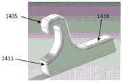
本文描述的任何腭扩张器还可以包括一个或多个脱离区域,例如,位于所述一对牙齿接合区域中的至少一个的颊侧上,所述脱离区域被构造成接收拉力。所述脱离区域可以被构造为突起、腔、凸片等,用于与移除工具和/或使用者的手指接合,以施加具有用于移除腭扩张器的侧向向外分量的拉力,通常通过使破坏区域弯曲或断裂来将腭扩张器从牙齿(包括从牙齿上或牙齿与腭扩张器之间的任何附件)脱开,使得腭扩张器可以被移除。例如,脱离区域可以是颊侧的下边缘上或附近的狭槽、凸缘、凹口、唇缘或间隙中的一个或多个。脱离区域的尺寸可以设置成接收工具和/或手指或指甲。例如,脱离区域可以包括袋状部、间隙等,在约1mm和15mm之间(例如,在约1mm和12mm之间、在约1mm和10mm之间、在约1mm和8mm之间、在约1mm和5mm之间等)。Any of the palatal expanders described herein may also include one or more disengagement regions, eg, on the buccal side of at least one of the pair of tooth engagement regions, configured to receive a pulling force. The disengagement area may be configured as a protrusion, cavity, tab, etc. for engagement with a removal tool and/or a user's finger to apply a pulling force having a laterally outward component for removal of the palatal dilator, The palatal expander is usually disengaged from the tooth (including any attachments from the tooth or between the tooth and the palatal expander) by bending or breaking the disrupted area so that the palatal expander can be removed. For example, the disengagement region may be one or more of a slot, lip, notch, lip, or gap on or near the lower edge of the buccal side. The breakaway area may be sized to receive an implement and/or a finger or nail. For example, the disengagement area may include pockets, gaps, etc., between about 1 mm and 15 mm (e.g., between about 1 mm and 12 mm, between about 1 mm and 10 mm, between about 1 mm and 8 mm, between about 1 mm and 5mm, etc.).
这些设备中的任一个可包括一个或多个(例如,多个)竖直狭槽或狭缝,从颊侧的底部朝向破坏区域延伸。这些狭槽或狭缝可以允许颊侧的一部分(特别是在一个或多个附件的任一侧上)弯曲或拉离牙龈和牙齿,并从一个或多个附件脱开。Any of these devices may include one or more (eg, a plurality) of vertical slots or slits extending from the bottom of the buccal side towards the disrupted area. These slots or slits may allow a portion of the buccal side (especially on either side of the appendage(s)) to flex or pull away from the gums and teeth and disengage from the appendage(s).
例如,用于扩张患者的腭的腭扩张器外壳设备可以被构造成易于移除,所述设备可以包括:一对牙齿接合区域,每个牙齿接合区域从前部到后部地延伸,并且被构造成佩戴在患者的牙齿上,其中每个牙齿接合区域包括咬合侧和颊侧;连接所述一对牙齿接合区域的腭区域,其中所述腭区域被构造成,当设备被患者佩戴时,所述腭区域在所述一对牙齿接合区域之间施加侧向力;以及破坏区域,从前部到后部地延伸,所述破坏区域的机械强度小于与该破坏区域的任一侧相邻的区域的机械强度,因此当具有侧向向外分量的拉力被施加到一对牙齿接合区域中的一个或两个的颊侧时,所述破坏区域可预见地弯曲或断裂。For example, a palatal dilator housing device for dilating a patient's palate can be configured for easy removal, the device can include a pair of tooth-engaging regions, each extending from anterior to posterior, and configured to be worn on the patient's teeth, wherein each tooth-engaging region includes an occlusal side and a buccal side; a palatal region connecting the pair of tooth-engaging regions, wherein the palatal region is configured so that when the device is worn by the patient, the said palatal region exerts a lateral force between said pair of tooth-engaging regions; and a disrupted region extending from anterior to posterior, said disrupted region having less mechanical strength than regions adjacent to either side of said disrupted region mechanical strength such that when a pulling force having a laterally outward component is applied to the buccal side of one or both of a pair of tooth-engaging regions, the failure region predictably bends or fractures.
本文描述的任何设备可适于在不降低腭扩张器保持在患者的适当位置的保持力或能力的情况下使得移除腭扩张器更容易。例如,这些腭扩张器中的任何一个可以包括破坏区域。这些设备中的任何一个也可以或者替代地包括位于腭扩张器的一个或两个颊侧上的脱离区域。如上所述,脱离区域(其可被称为移除手柄、移除腔、移除把手、移除附件、移除狭槽等)可包括位于面向上侧或面向下侧上的间隙、狭槽、开口等,其可适于允许使用者将指甲和/或移除工具插入在其中以从牙齿移除腭扩张器。所述脱离区域可被构造成使所述破坏区域变形或断裂,并将所述腭扩张器从患者的牙齿释放。脱离区域可以被构造为腭扩张器的颊侧上的唇缘、凸缘或突起。因此,破坏区域可形成铰接区域;在一些变型中,该铰接区域位于咬合面和颊侧之间,使得操作脱离区域可以将腭扩张器的颊侧拉离患者的牙齿和/或从任一附件上拉下来,从而可将其移除。这些腭扩张器中的任一个可以包括狭缝、狭槽、间隙等,其从腭扩张器的边缘朝向颊侧上的咬合面向上延伸,允许腭扩张器的全部或部分向上拉并脱离牙齿。Any of the devices described herein may be adapted to facilitate removal of the palate dilator without reducing the retention or ability of the palate dilator to remain in place on the patient. For example, any of these palatal dilators may include a disrupted region. Any of these devices may also or alternatively include a breakaway area on one or both buccal sides of the palatal expander. As noted above, the disengagement area (which may be referred to as a removal handle, removal cavity, removal handle, removal attachment, removal slot, etc.) may include a gap, slot, on the upper facing side or the lower facing side. , openings, etc., which may be adapted to allow a user to insert a fingernail and/or a removal tool therein to remove the palatal expander from the teeth. The disengagement region may be configured to deform or fracture the disruption region and release the palatal expander from the patient's teeth. The breakaway area may be configured as a lip, flange or protrusion on the buccal side of the palatal dilator. Thus, the disrupted area may form a hinged area; in some variations, the hinged area is located between the occlusal surface and the buccal side such that the operative disengagement area can pull the buccal side of the palatal expander away from the patient's teeth and/or from either attachment. Pull up and down to remove it. Any of these palatal expanders may include slits, slots, gaps, etc. extending upwardly from the edge of the palatal expander towards the occlusal surface on the buccal side, allowing all or part of the palatal expander to be pulled up and out of the teeth.
本文还描述了适于舒适性的腭扩张器,其具有变化的厚度。例如,在这些变型中的任一种中,腭扩张器可包括腭扩张器的腭弓部分中的内底表面,在佩戴时所述内底表面面向患者的舌头,所述内底表面与相对表面(与佩戴腭扩张器的患者的腭匹配)相比是平滑或平坦的。该面向舌头的一侧可以有一个倒圆的表面,并且与患者的实际腭相比,在形貌上不包括任何急剧的转变。在这些示例中的任何一个中,本文描述的设备可以具有不同的(包括可变的)厚度。在一些变型中,所述设备可包括朝向腭扩张器设备的前部变窄的腭区域。在这些变型中的任一个中,腭扩张器的后部分可以更薄和/或从腭扩张器中切除(移除),这可以防止或限制呕吐。Also described herein are palatal dilators adapted for comfort, having varying thicknesses. For example, in any of these variations, the palate dilator may include an inner bottom surface in the palatal arch portion of the palate dilator that faces the patient's tongue when worn, the inner bottom surface being opposite to the The surface (matching the palate of the patient wearing the palate expander) is smooth or flat. The tongue-facing side may have a rounded surface and not include any sharp transitions in topography compared to the patient's actual palate. In any of these examples, the devices described herein can have different (including variable) thicknesses. In some variations, the device may include a palatal region that narrows toward the front of the palate dilator device. In either of these variations, the posterior portion of the palate dilator may be thinner and/or cut (removed) from the palate dilator, which may prevent or limit vomiting.
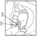
可通过施加力(例如,拉力)以使破坏区域弯曲和/或断裂来移除本文描述的腭扩张器。例如,本文描述的是从患者的牙齿移除腭扩张器外壳设备的方法,其可包括以下步骤:当第一牙齿接合区域佩戴在患者牙齿的第一部分上,第二牙齿接合区域佩戴在患者牙齿的第二部分上时,并且当在第一牙齿接合区域和第二牙齿接合区域之间延伸的腭区域在第一牙齿接合区域与第二牙齿接合区域之间施加侧向力时,对腭扩张器外壳设备的颊侧施加拉力,其中,所述拉力使所述腭扩张器外壳设备的破坏区域沿着所述破坏区域断裂或弯曲,并使所述腭扩张器外壳设备从所述患者的第一或第二组牙齿脱开;以及将所述腭扩张器外壳设备从患者的口腔移除。The palatal expanders described herein can be removed by applying a force (eg, pulling force) to bend and/or break the disrupted region. For example, described herein is a method of removing a palatal expander housing device from a patient's teeth, which may include the steps of: when a first tooth engaging region is worn on a first portion of a patient's teeth, a second tooth engaging region is worn on a first portion of the patient's teeth and when the region of the palate extending between the first tooth-engaging region and the second tooth-engaging region exerts a lateral force between the first tooth-engaging region and the second tooth-engaging region, expansion of the palate The buccal side of the palatal dilator housing device applies a pulling force, wherein the pulling force breaks or bends the failure region of the palatal dilator housing device along the failure region and removes the palatal dilator housing device from the patient's first dislodging one or the second set of teeth; and removing the palatal expander housing device from the patient's mouth.
如上所述,拉力可以是任何适当的力。例如,施加拉力包括施加约100N、约90N、约80N、约70N、约60N、约50N、约40N、约30N、约20N等。施加的拉力可为约5N或更大、约7.5N或更大、约8N或更大、约10N或更大、约12N或更大、约15N或更大等(例如,在约5-100N之间等)。所施加的拉力可以是指力的侧向向外分量。通常,这种侧向向外的力也可以向下定向或在侧向向外(例如,当佩戴时,与腭扩张器的平面平行和/或与患者的上腭的平面平行)和向下(例如,当腭扩张器被佩戴在上颌时,远离外咬合面,和/或朝向下颌)之间定向。在一些变型中,当腭扩张器被佩戴时,力可以施加在侧向向外方向与向下方向之间的方向上。施加拉力可包括使用具有侧向向外的力分量、或侧向向外的力分量和向下的分量的力来拉动腭扩张器的颊侧。例如,施加拉力可包括拉动腭扩张器的颊侧的边缘。As noted above, the pulling force may be any suitable force. For example, applying a tensile force includes applying about 100N, about 90N, about 80N, about 70N, about 60N, about 50N, about 40N, about 30N, about 20N, and the like. The tension applied may be about 5N or greater, about 7.5N or greater, about 8N or greater, about 10N or greater, about 12N or greater, about 15N or greater, etc. (e.g., between about 5-100N between, etc.). The applied pulling force may refer to a laterally outward component of the force. Typically, this laterally outward force can also be directed downward or laterally outward (e.g., when worn, parallel to the plane of the palate expander and/or parallel to the plane of the patient's palate) and downward ( For example, when the palatal expander is worn on the upper jaw, away from the outer occlusal surface, and/or toward the lower jaw). In some variations, when the palatal expander is worn, the force may be applied in a direction between a laterally outward direction and a downward direction. Applying the pulling force may include pulling the buccal side of the palatal dilator with a force having a laterally outward force component, or a laterally outward force component and a downward component. For example, applying the pulling force may include pulling a buccal edge of the palatal dilator.
通常,施加拉力可导致破坏区域沿着破坏区域弯曲或断裂,从而使腭扩张器外壳设备从牙齿脱开,包括从腭扩张器外壳设备和患者牙齿之间的一个或多个附件脱开。施加拉力可使破坏区域以铰接方式沿着破坏区域弯曲。施加拉力可导致破坏区域沿着破坏区域断裂。Typically, application of a pulling force may cause the failure region to bend or fracture along the failure region, thereby disengaging the palatal expander housing device from the teeth, including from one or more attachments between the palatal expander housing device and the patient's teeth. Applying a pulling force causes the damaged area to bend in a hinged fashion along the damaged area. Applying a pulling force can cause the damaged area to fracture along the damaged area.
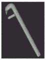
拉力可由使用者使用其手指或工具来手动施加,诸如施加拉力包括使用工具来施加拉力。所述工具可以包括长臂和支点区域,该支点区域杠杆抵靠腭扩张器的一部分。在一些变型中,施加拉力包括使用指甲来施加拉力。施加拉力可包括在腭扩张器外壳设备的颊侧上的脱离区域上拉动。The tension may be applied manually by a user using his fingers or a tool, such as applying tension includes using a tool to apply tension. The tool may include a long arm and a fulcrum region that levers against a portion of the palatal dilator. In some variations, applying the pulling force includes using a fingernail to apply the pulling force. Applying the pulling force may include pulling on the disengagement area on the buccal side of the palatal expander housing device.
一种从患者牙齿移除腭扩张器外壳设备的方法,所述方法可以包括:当第一牙齿接合区域佩戴在患者的第一组牙齿上并且第二牙齿接合区域佩戴在患者的第二组牙齿上时,并且当在第一牙齿接合区域和第二牙齿接合区域之间延伸的腭区域在第一牙齿接合区域与第二牙齿接合区域之间施加侧向力时,对腭扩张器外壳设备的颊侧施加拉力,其中,所述拉力使所述腭扩张器外壳设备的破坏区域在预定位置处断裂或弯曲并从患者的第一或第二组牙齿脱开,其中,所述破坏区域沿着腭扩张器外壳从前部到后部地延伸,并且包括机械强度小于腭扩张器的围绕所述破坏区域的区域的材料强度的一个或多个区域;以及从患者的口腔移除所述腭扩张器外壳设备。A method of removing a palatal expander housing device from a patient's teeth, the method may comprise: when a first tooth engaging region is worn on a first set of teeth of a patient and a second tooth engaging region is fitted on a second set of teeth of a patient and when the palatal region extending between the first tooth engagement region and the second tooth engagement region exerts a lateral force between the first tooth engagement region and the second tooth engagement region, the palatal expander housing device buccally applying a pulling force, wherein the pulling force causes a failure region of the palatal expander housing device to break or bend at a predetermined location and disengage from the patient's first or second set of teeth, wherein the failure region is along the palatal dilator housing extends from the front to the rear and includes one or more regions of mechanical strength that are less than the material strength of the palatal dilator's region surrounding the disrupted region; and removing the palatal dilator from the patient's mouth Shell device.
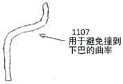
本文还描述了用于形成一个或一系列腭扩张器的方法以及制造和使用其的方法,其中腭扩张器被构造成在患者的上牙弓与腭扩张器的上(例如,面向腭)表面之间包括一个或多个间隙或间距区域。例如,这些设备中的任一个可以被构造成包括间隙或凹形通道或区域,以防止在牙龈线附近(例如,在设备的颊侧和/或舌侧上)的撞击。这些设备中的任一个可以被构造成在腭扩张器的上(例如,面向腭)表面与腭之间包括间隙。Also described herein are methods for forming one or a series of palatal expanders and methods of making and using the same, wherein the palate expanders are configured to be on the upper (e.g., palate-facing) surface of the patient's upper dental arch and the palate expanders Include one or more gaps or spacing regions in between. For example, any of these devices may be configured to include gaps or concave channels or areas to prevent impingement near the gum line (eg, on the buccal and/or lingual sides of the device). Either of these devices can be configured to include a gap between the upper (eg, palate-facing) surface of the palate dilator and the palate.
还描述了使用这些设备中的任一个来执行腭扩张的方法和设备。例如,本文描述了用于充分扫描患者的口腔(特别包括上牙弓)以便可以形成本文描述的腭扩张器设备的方法和设备。Methods and devices for performing palatal expansion using any of these devices are also described. For example, described herein are methods and devices for sufficiently scanning a patient's oral cavity, including in particular the upper dental arch, so that the palatal expander devices described herein can be formed.
描述了应用或附接本文描述的腭扩张器的方法,包括患者将腭扩张器施加到她/他自己的牙齿上的方法。本文还描述了附件(其可替代地称为保持附件、保持柱等)和用于将附件附接到患者牙齿上的模板,可以被构造成将腭扩张器可释放地固定到患者的牙齿。还描述了形成附件模板和/或将附件附接到牙齿的方法。Methods of applying or attaching the palatal expanders described herein are described, including methods for a patient to apply the palatal expanders to her/his own teeth. Also described herein are attachments (which may alternatively be referred to as retention attachments, retention posts, etc.) and templates for attaching the attachment to the patient's teeth, which may be configured to releasably secure the palatal expander to the patient's teeth. Methods of forming an accessory template and/or attaching an accessory to a tooth are also described.
本文还描述了用于从患者牙齿移除腭扩张器的方法和设备。例如,本文描述了当腭扩张器固定到患者牙齿上时帮助人(特别是但不限于患者)移除腭扩张器的移除工具。Also described herein are methods and devices for removing a palatal expander from a patient's teeth. For example, described herein is a removal tool that assists a person, particularly but not limited to a patient, in removing a palatal expander while the palate expander is secured to the patient's teeth.
本文还描述了制造本文所描述的任何设备的方法。Also described herein are methods of making any of the devices described herein.
例如,本文描述了用于扩张患者的腭的腭扩张器设备。腭扩张器设备可包括:由腭区域以及两个或更多个附接区域连接的一对牙齿接合区域,每个附接区域被构造成与结合到患者牙齿的附件联接,其中所述腭区域被构造成,当被患者佩戴时,所述腭区域在所述一对牙齿接合区域之间施加8到160N之间的力;其中每个牙齿接合区域包括咬合侧和颊侧,其中所述咬合侧比所述腭区域薄,并且所述颊侧比所述咬合侧薄。For example, described herein is a palate dilator device for dilating a patient's palate. The palatal expander device may comprise a pair of tooth-engaging regions connected by a palatal region and two or more attachment regions each configured to couple with an appendage bonded to a patient's teeth, wherein the palatal region is configured so that, when worn by a patient, the palatal region exerts a force between 8 and 160 N between the pair of tooth-engaging regions; wherein each tooth-engaging region includes an occlusal side and a buccal side, wherein the occlusal The buccal side is thinner than the palatal area, and the buccal side is thinner than the occlusal side.
腭区域可以为约1-5mm之间的厚度(例如,1.5到3mm之间、2到2.5mm的厚度等)。咬合侧可以具有约0.5-2mm之间(例如,0.5至1.75mm之间、0.75至1.7mm之间等)的厚度。颊侧可以具有约0.25-1mm之间(例如,0.35至0.85mm之间,约0.4至0.8mm之间等)的厚度。The palatal region may be between about 1-5 mm in thickness (eg, between 1.5 and 3 mm in thickness, 2 to 2.5 mm in thickness, etc.). The occlusal side may have a thickness of between about 0.5-2 mm (eg, between 0.5 and 1.75 mm, between 0.75 and 1.7 mm, etc.). The buccal side may have a thickness of between about 0.25-1 mm (eg, between 0.35 and 0.85 mm, between about 0.4 and 0.8 mm, etc.).
如上所述,这些设备中的任一个可以包括位于设备的颊侧上的脱离区域,以在装置附接到患者的牙齿后帮助移除装置。为了加宽腭而施加的力可能使得难以容易地移除该设备。可以使用颊侧定位的脱离区域(例如,凹口、间隙、把手、凸片、狭槽等)来更容易地从牙齿移除该设备,特别是当使用附件将设备固定在牙齿上时。脱离区域可提供把手或手柄区域,用于施加拉力以移除腭扩张器。脱离区域可以位于(一个或多个)颊侧上或从所述颊侧延伸,并且当设备被佩戴时脱离区域可以与患者的牙龈间隔至少0.25到1mm,并且可以靠近设备的颊侧的底部边缘(或从底部边缘延伸,或在底部边缘上方)。例如,颊侧的底部边缘可以被构造为从装置的颊侧沿着颊区域的全部或一侧(例如,在1mm和5cm之间,例如,1mm至4cm、1mm至3cm、5mm至4cm等)延伸的脱离区域。延伸部分可以被构造成在患者牙龈下方并远离患者牙龈延伸,例如,当设备被患者佩戴时,形成约0.25-1mm的间隙。这些设备中的任一个可以包括从颊侧的底部朝向咬合侧延伸的一个或多个竖直狭槽或狭缝。特别地,这些狭槽或狭缝可以位于脱离区域的任一侧。As noted above, either of these devices may include a breakaway area on the buccal side of the device to facilitate removal of the device after it has been attached to the patient's teeth. The force applied to widen the palate may make it difficult to easily remove the device. Buccally located breakaway areas (eg, notches, gaps, handles, tabs, slots, etc.) may be used to more easily remove the device from the tooth, especially when attachments are used to secure the device to the tooth. The breakaway area may provide a grip or handle area for applying pulling force to remove the palatal expander. The breakaway region may be located on or extend from the buccal side(s), and the breakaway region may be spaced at least 0.25 to 1 mm from the patient's gums when the device is worn, and may be near the bottom edge of the buccal side of the device (either extending from, or above, the bottom edge). For example, the bottom edge of the buccal side can be configured from the buccal side of the device along all or one side of the buccal area (e.g., between 1 mm and 5 cm, e.g., 1 mm to 4 cm, 1 mm to 3 cm, 5 mm to 4 cm, etc.) Extended breakaway area. The extension portion may be configured to extend below and away from the patient's gums, eg, forming a gap of about 0.25-1 mm when the device is worn by the patient. Either of these devices may include one or more vertical slots or slits extending from the bottom of the buccal side towards the occlusal side. In particular, these slots or slits may be located on either side of the disengagement area.
这些设备中的任一个可以在该设备的面向舌头的一侧上是平滑的。例如,腭区域可以包括具有第一表面曲率的上凸表面,该上凸表面包括与患者的腭中的沟槽和脊对准的多个沟槽和脊;而且其中所述腭区域包括具有比第一表面曲率更平滑的第二表面曲率的下凹表面。更平滑可能意味着具有较少和/或更少程度(深、高)的沟槽和/或脊。Either of these devices may be smooth on the tongue-facing side of the device. For example, the palatal region may include a convex surface having a first surface curvature, the convex surface including a plurality of grooves and ridges aligned with grooves and ridges in the patient's palate; A concave surface with a smoother curvature of the first surface and a smoother curvature of the second surface. Smoother may mean having fewer and/or lesser degree (deep, high) grooves and/or ridges.
本文还描述了制造腭扩张器设备的方法,所述方法包括:接收患者上牙弓的模型(例如,数字模型、手动模型等);以及形成腭扩张器,所述腭扩张器具有通过腭区域连接的一对牙齿接合区域和向前延伸的一个或多个破坏区域。该方法还可包括将腭扩张器形成为包括两个更多个附接区域,每个附接区域被构造为与结合到患者牙齿的附件联接,其中每个牙齿接合区域被构造为装配在患者的牙齿上,并且每个牙齿接合区域包括咬合侧和颊侧,而且其中咬合侧包括脱离区域,所述脱离区域被构造成与患者的指甲接合以将附接区域中的至少一个从患者牙齿上的附件上脱开。形成该设备可包括:形成本文描述的任何特征,包括脱离区域、狭缝/狭槽;使面向舌头的一侧平滑;在设备中形成开口;改变不同区域相对于彼此的和/或在每个区域内的厚度等。例如,形成可以包括通过使腭区域的底表面相对于腭区域的相对顶表面平滑来形成腭区域。Also described herein is a method of manufacturing a palatal expander device, the method comprising: receiving a model (e.g., a digital model, a manual model, etc.) of a patient's upper dental arch; A joined pair of tooth occlusal regions and one or more disrupted regions extending forward. The method may also include forming the palatal expander to include two more attachment regions, each attachment region configured to couple with an attachment bonded to the patient's teeth, wherein each tooth engagement region is configured to fit on the patient's teeth. and each tooth-engaging region includes an occlusal side and a buccal side, and wherein the occlusal side includes a breakaway region configured to engage a patient's nail to separate at least one of the attachment regions from the patient's teeth detach from the attachment. Forming the device may include: forming any of the features described herein, including breakaway areas, slits/slots; smoothing the tongue-facing side; forming openings in the device; area thickness, etc. For example, forming may include forming the palatal region by smoothing a bottom surface of the palatal region relative to an opposing top surface of the palatal region.
例如,一种制造腭扩张器的方法可以包括:接收患者上牙弓的模型;形成腭扩张器,所述腭扩张器具有一对牙齿接合区域和两个或更多个附接区域,所述一对牙齿接合区域通过腭区域连接,每个附接区域被构造成与结合到患者牙齿的附件联接;形成在一个或多个腭区域、第一牙齿接合区域(例如,沿着颊侧、咬合侧、颊侧和咬合侧之间等)、第二牙齿接合区域(沿着颊侧、咬合侧、颊侧和咬合侧之间等)从前部到后部地延伸的破坏区域。每个牙齿接合区域可被构造成装配在患者的牙齿上,并且每个牙齿接合区域包括咬合侧和颊侧。该方法还可以包括在颊侧形成脱离区域,该脱离区域具有间隙,所述间隙被构造成与患者的指甲或长形工具接合,并且将至少一个附接区域从患者牙齿上的附件脱开。For example, a method of making a palatal expander may include: receiving a model of a patient's upper dental arch; forming the palatal expander having a pair of tooth-engaging regions and two or more attachment regions, the one Pair of tooth-engaging regions connected by palatal regions, each attachment region configured to couple with an attachment coupled to the patient's teeth; formed in one or more palatal region, first tooth-engaging region (e.g., along buccal, occlusal , between the buccal and occlusal sides, etc.), the second tooth engagement area (along the buccal, occlusal, between the buccal and occlusal sides, etc.) a disrupted area extending from anterior to posterior. Each tooth-engaging region may be configured to fit over the patient's teeth, and each tooth-engaging region includes an occlusal side and a buccal side. The method may also include forming a breakaway region buccally having a gap configured to engage a patient's nail or elongate tool and detach at least one attachment region from an attachment on the patient's teeth.
在这些方法中的任一种中,牙齿接合区域可包括牙齿接合区域的颊侧的延伸部分,所述延伸部分从患者牙龈延伸,以当设备由患者佩戴时形成约0.25-1mm的间隙。所述牙齿接合区域可包括从所述牙齿接合区域的颊侧延伸的突起。腭扩张器可被构造成当由患者佩戴时接触患者牙齿的舌侧,并在牙齿接合区域之间施加8到160N的力。所述腭扩张器可被构造成不接触当被患者佩戴时邻近患者牙齿的舌侧的牙龈和患者的腭的中线中的任一个或两者。In any of these methods, the tooth-engaging region may include a buccal extension of the tooth-engaging region extending from the patient's gums to form a gap of about 0.25-1 mm when the device is worn by the patient. The tooth-engaging region may include a protrusion extending from a buccal side of the tooth-engaging region. The palatal expander may be configured to contact the lingual side of the patient's teeth when worn by the patient, and exert a force of 8 to 160 N between the teeth engaging areas. The palatal expander may be configured not to contact either or both of the gingiva adjacent to the lingual side of the patient's teeth and the midline of the patient's palate when worn by the patient.
该设备可以任何适当的方式形成,包括通过三维(3D)打印形成。例如,接收患者上牙弓的模型可以包括接收患者牙齿、牙龈和腭区域的数字模型。The device may be formed in any suitable manner, including by three-dimensional (3D) printing. For example, receiving a model of the patient's upper dental arch may include receiving digital models of the patient's teeth, gums, and palatal regions.
通常,这些腭扩张器中的任一个可以被构造成使得全部或一部分(例如,中腭区域,例如,被构造成与骨缝(suture)相对定位)在装置被佩戴时与患者的腭间隔开一定的最小距离,例如,在0.01和5mm之间(例如,0.02mm或更大、0.03mm或更大、0.04mm或更大、大于0.05mm或更大、0.06mm或更大、0.07mm或更大、0.1mm或更大、0.15mm或更大、0.2mm或更大、0.25mm或更大等)。当通过(例如,从数字模型)对患者的牙弓建模而形成腭扩张器(包括腭区域)时可以确定该最小距离。包括该最小距离例如对佩戴(一个或多个)腭扩张器时防止软和/或硬腭的疼痛或刺激可能是特别有帮助的。Generally, any of these palatal expanders can be configured such that all or a portion (e.g., the middle palate region, e.g., configured to be positioned opposite the suture) is spaced from the patient's palate when the device is worn A certain minimum distance, for example, between 0.01 and 5mm (for example, 0.02mm or greater, 0.03mm or greater, 0.04mm or greater, greater than 0.05mm or greater, 0.06mm or greater, 0.07mm or larger, 0.1mm or larger, 0.15mm or larger, 0.2mm or larger, 0.25mm or larger, etc.). This minimum distance may be determined when forming the palatal expander (including the palatal region) by modeling the patient's dental arch (eg, from a digital model). Including this minimum distance may be particularly helpful, for example, to prevent pain or irritation of the soft and/or hard palate when wearing the palate expander(s).
腭扩张器的腭区域的面向腭表面与患者的腭之间的该空间可以称为空隙。该间距可以是正的(例如,形成间隙),或者在腭区域的一些区域中可以是负的,例如,撞击在患者的腭上,以便提供力来使腭扩张。可以通过比较患者的腭的实际或预测(例如,对于扩张治疗的后期阶段)模型与腭扩张器外(面向腭)表面来识别负空隙。实际或早期模型可以是患者牙弓的数字(虚拟)或模铸件。在治疗的后期阶段,可以从数字模型估计空隙,其中,通过变形腭区域r来预测患者的腭区域形貌,从而反映治疗进展。This space between the palate-facing surface of the palate region of the palate expander and the patient's palate may be referred to as the void. This spacing can be positive (eg, to form a gap), or can be negative in some areas of the palate area, eg, to impinge on the patient's palate to provide a force to expand the palate. Negative space can be identified by comparing the actual or predicted (eg, for later stages of dilation treatment) model of the patient's palate with the outer (palate-facing) surface of the palatal expander. The actual or early model may be a digital (virtual) or molded cast of the patient's dental arch. In later stages of treatment, the void can be estimated from the numerical model, where the topography of the patient's palatal region is predicted by deforming the palatal region r, reflecting the progress of the treatment.
例如,通过在被构造为佩戴于与软腭区域相对的区域中包括大于某个最小值(例如,见上文,诸如0.1mm、0.2mm等)的正空隙,可以避免与患者的腭的软腭区域接触。通常,这些设备中的任一个可以被构造成使得中腭区域(例如,与中腭骨缝相对)在佩戴时偏离患者的腭。在一些变型中,间隔距离可以在该中腭区域中最大。在一些变型中,间隔距离可能侧向减小,而可以侧向存在负空隙(例如,施加力接触)。所述空隙可能在一序列或一系列矫正器上变化。例如,初始(早期)阶段可以被构造为具有比后期阶段更低的最大正空隙,后期阶段可以具有更大的最大空隙。这些设备中的任一个可以具有后部比前部更大的正空隙。在一些变型中,最大正空隙可以从中腭区域的最大值朝向牙齿渐缩(taper,变小)。For example, by including a positive clearance greater than some minimum (e.g., see above, such as 0.1mm, 0.2mm, etc.) in the region configured to be worn opposite the soft palate region, it is possible to avoid contact with the soft palate region of the patient's palate. touch. In general, any of these devices can be configured such that the mid-palate region (eg, opposite the mid-palatine suture) is offset from the patient's palate when worn. In some variations, the separation distance may be greatest in the mid-palate region. In some variations, the separation distance may decrease laterally, while negative clearance may exist laterally (eg, force contact is applied). The gap may vary over a sequence or sequence of aligners. For example, an initial (early) stage can be configured to have a lower maximum positive gap than a later stage, which can have a larger maximum gap. Either of these devices may have a greater positive clearance at the rear than at the front. In some variations, the maximum positive space may taper from a maximum in the midpalatal region towards the teeth.
例如,在一些变型中,当患者佩戴该装置时,腭区域可以被构造成具有距患者的中腭区域大于0.1mm的空隙。For example, in some variations, the palate region may be configured to have a clearance greater than 0.1 mm from the patient's middle palate region when the device is worn by the patient.
这些设备中的任一个可包括两个或更多个附接区域,每个附接区域被构造成与结合到患者牙齿的附件联接。附接区域可以是开口、凹坑、狭槽、通道等,用于固定到结合到患者牙齿的附件。附接区域可以被构造为固定到患者的牙齿,但是允许通过弯曲腭扩张器的一部分(例如,脱离区域)从附件移除设备,该部分可以在颊侧上,包括从颊侧延伸。Any of these devices may include two or more attachment regions, each configured to couple with an accessory bonded to the patient's teeth. The attachment area may be an opening, recess, slot, channel, etc., for securing to an accessory bonded to the patient's teeth. The attachment area may be configured to be fixed to the patient's teeth, but allow removal of the device from the attachment by bending a portion of the palatal expander (eg, a breakaway area), which may be on, including extending from, the buccal side.
通常,如上所述,本文所述的腭扩张器中的任一个可包括可变厚度(例如,在相对的上表面和下表面之间垂直的横向厚度)。例如,腭区域的平均和/或最大厚度可以大于咬合面(例如,抵靠牙齿的咬合面佩戴的侧面)的平均或最大厚度;颊面(例如,抵靠牙齿的颊面佩戴的侧面)的平均或最大厚度可以小于咬合面和/或腭表面的平均或最大厚度。可替代地或另外地,在一些变型中,可以切除咬合面的全部或一部分。通常,腭区域的前部部分可以具有与腭区域的后部部分不同的平均厚度。例如,腭区域的前部部分可以比腭区域的后部部分薄;或者,腭扩张器的前部部分可以比后部部分更厚。In general, any of the palatal dilators described herein can include a variable thickness (eg, perpendicular transverse thickness between opposing upper and lower surfaces), as described above. For example, the average and/or maximum thickness of the palatal region may be greater than the average or maximum thickness of the occlusal surface (e.g., the side worn against the occlusal surface of the teeth); The average or maximum thickness may be less than the average or maximum thickness of the occlusal and/or palatal surfaces. Alternatively or additionally, in some variations all or a portion of the occlusal surface may be resected. In general, the anterior portion of the palatal region may have a different average thickness than the posterior portion of the palatal region. For example, the anterior portion of the palatal region may be thinner than the posterior portion of the palatal region; alternatively, the anterior portion of the palatal dilator may be thicker than the posterior portion.
如上所述,这些设备中的任一个可以包括从所述设备的颊侧延伸的延伸部分,其中所述延伸部分被构造成,当患者佩戴设备时,所述延伸部分邻近和远离患者的牙龈延伸,以形成约0.25和1mm之间的间隙。延伸部分的长度可以被确定为使其不接触内脸颊表面。As noted above, any of these devices may include an extension extending from the buccal side of the device, wherein the extension is configured to extend adjacent to and away from the patient's gums when the device is worn by the patient. , to form a gap between approximately 0.25 and 1mm. The length of the extension may be determined such that it does not contact the inner cheek surface.
本文还描述了使用一系列患者可移除的腭扩张器扩张患者的腭的方法,该方法包括:除了来自一系列患者可移除的腭扩张器中的最后一个腭扩张器之外,以预定的逐渐增加的宽度顺序来顺序地佩戴多个腭扩张器中的每个,其中:每个腭扩张器包括一对牙齿接合区域和两个或更多个附接区域,所述一对牙齿接合区域通过腭区域连接,其中牙齿接合区域佩戴在患者牙齿上,且附接区域联接到患者的牙齿上的附件,其中所述腭扩张器中的至少一个包括用于移除的破坏区域,如本文所述。每个腭扩张器可佩戴0.5天至14天之间;并且可以通过施加如本文所述的拉力使破坏区域弯曲或断裂,而使至少一个附接区域从患者牙齿上的附件脱开,来移除每个腭扩张器。因此,佩戴该设备可以包括在该时间段内将该设备移除少于佩戴时间的一定百分比(例如,2%、5%、7%、10%等)的时间(例如,一天中的数分钟到一小时等)。Also described herein is a method of dilating a patient's palate using a series of patient-removable palate expanders, the method comprising: except for the last palate expander from the series of patient-removable palate Each of the plurality of palatal expanders is sequentially worn in sequence of increasing widths, wherein: each palatal expander includes a pair of teeth engaging regions and two or more attachment regions, the pair of teeth engaging The regions are connected by the palatal region, wherein the tooth-engaging region is worn on the patient's teeth, and the attachment region is coupled to an attachment on the patient's teeth, wherein at least one of the palatal expanders includes a destruction region for removal, as herein mentioned. Each palatal expander can be worn for between 0.5 days to 14 days; and can be removed by applying a pulling force as described herein to bend or fracture the disrupted region, causing at least one attachment region to disengage from the attachment on the patient's teeth. Remove each palatal dilator. Thus, wearing the device may include removing the device for less than a certain percentage (e.g., 2%, 5%, 7%, 10%, etc.) to an hour etc).
提供了一种形成腭扩张器的方法。所述方法可以包括:收集腭表面的虚拟表示,所述腭表面具有凸表面几何形状,所述凸表面几何形状被构造成,当所述腭扩张器插入所述患者的腭时,所述凸表面几何形状与所述患者的腭相匹配;收集与腭表面相对的舌表面的虚拟表示,所述舌表面具有凹表面几何形状,所述凹表面几何形状被构造成,当所述腭扩张器插入腭区域时,所述凹表面几何形状在患者的舌头和腭扩张器之间提供间隙;收集围绕腭表面和舌表面的至少一部分的多个侧壁的虚拟表示,所述多个侧壁被构造成,当所述腭扩张器插入腭区域时,所述多个侧壁对所述患者的腭和牙齿的舌区域中的一个或多个施加侧壁力,所述多个侧壁具有至少一个移除结构以接收移除力;收集本体的虚拟表示,响应于对所述移除结构施加移除力,所述本体具有第一变形度量,该第一变形度量与所述本体的实质性第一变形相对应;收集一个或多个破坏区域的虚拟表示,响应于对所述移除结构施加移除力,所述一个或多个破坏区域具有与所述一个或多个破坏区域的实质性第二变形相对应的第二变形度量,所述第二变形度量大于第一变形度量;以及提供使用所述腭表面的虚拟表示、所述舌表面的虚拟表示、所述多个侧壁的虚拟表示、所述本体的虚拟表示以及所述一个或多个破坏区域的虚拟表示来制造所述腭扩张器的指令。A method of forming a palatal expander is provided. The method may include collecting a virtual representation of a palatal surface having a convex surface geometry configured such that when the palatal dilator is inserted into the patient's palate, the convex matching the surface geometry to the patient's palate; collecting a virtual representation of the tongue surface opposite the palatal surface, the tongue surface having a concave surface geometry configured so that when the palatal dilator When inserted into the palatal region, the concave surface geometry provides a gap between the patient's tongue and the palatal expander; collecting a virtual representation of a plurality of side walls surrounding at least a portion of the palatal and lingual surfaces, the plurality of side walls being configured to apply a sidewall force to one or more of the patient's palate and lingual region of the teeth when the palatal expander is inserted into the palatal region, the plurality of sidewalls having at least a removal structure to receive the removal force; collecting a virtual representation of a body having a first deformation measure corresponding to the substantiality of the body in response to applying the removal force to the removal structure The first deformation corresponds to; collecting a virtual representation of one or more damaged regions, responsive to applying a removal force to said removal structure, said one or more damaged regions having a substantial a second deformation measure corresponding to a second deformation, the second deformation measure being greater than the first deformation measure; and providing a virtual representation using the palatal surface, the lingual surface, the plurality of sidewalls Instructions for manufacturing the palatal expander using a virtual representation of the body, a virtual representation of the body, and a virtual representation of the one or more destructed regions.
任何收集步骤均可以作为单个步骤或单个步骤的子部分来执行。例如,可以一起执行收集腭表面、与腭表面相对的舌表面和/或围绕腭表面和舌表面的至少一部分的多个侧壁的虚拟表示。收集该信息可以包括对患者口腔的扫描(例如,进行数字扫描)和/或对患者口腔的建模(例如,物理建模)。Any collection step can be performed as a single step or as a sub-part of a single step. For example, collecting a virtual representation of the palatal surface, the lingual surface opposite the palatal surface, and/or a plurality of side walls surrounding at least a portion of the palatal surface and the lingual surface may be performed together. Gathering this information may include scanning (eg, taking a digital scan) of the patient's mouth and/or modeling (eg, physically modeling) the patient's mouth.
腭扩张器可以包括:具有凸表面几何形状的腭表面,所述凸表面几何形状被构造成,当腭扩张器插入到患者的腭中时所述凸表面几何形状与患者的腭配合;与腭表面相对的舌表面,所述舌表面具有凹表面几何形状,所述凹表面几何形状被构造成当腭扩张器插入腭中时,所述凹表面几何形状在患者的舌头和腭扩张器之间提供间隙;多个侧壁,围绕腭表面和舌表面的至少一部分,所述多个侧壁被构造成,当腭扩张器插入腭中时,所述多个侧壁对所述患者的所述腭和牙齿的舌区域中的一个或多个施加侧壁力,所述多个侧壁具有至少一个移除结构以接收移除力;本体,响应于对所述移除结构施加移除力,具有与所述本体的实质性第一变形相对应的第一变形度量;以及用于响应于所述移除力而破坏腭扩张器的一部分的一个或多个装置(means),响应于对所述移除结构施加移除力,用于破坏所述腭扩张器的该部分的所述一个或多个装置具有对应于所述一个或多个破坏区域的实质性第二变形的第二变形度量,所述第二变形度量大于所述第一变形度量。The palate expander may comprise: a palatal surface having a convex surface geometry configured to mate with the patient's palate when the palate expander is inserted into the patient's palate; A surface opposite a lingual surface having a concave surface geometry configured to be between the patient's tongue and the palatal dilator when the palatal dilator is inserted into the palate A gap is provided; a plurality of side walls surrounding at least a portion of the palatal surface and the lingual surface, the plurality of side walls being configured so that when the palatal dilator is inserted into the palate, the plurality of side walls are opposed to the patient's one or more of the palate and lingual regions of the teeth apply a sidewall force, the plurality of sidewalls having at least one removal structure to receive the removal force; the body, in response to applying the removal force to the removal structure, having a first deformation measure corresponding to a substantial first deformation of the body; and one or more means for destroying a portion of the palatal dilator in response to the removal force, in response to the removal force. The removal structure applies a removal force, the one or more means for disrupting the portion of the palatal expander has a second deformation magnitude corresponding to a substantially second deformation of the one or more disrupted regions , the second deformation measure is greater than the first deformation measure.
本文描述的施加和移除腭扩张器的任何方法可以被构造为施加腭扩张器的方法,所述方法包括:通过将一个或多个附件放置到(一个或多个)附件联接区域中并将附件锁定到腭扩张器来将腭扩张器接合到患者的牙齿上。可以通过将附件驱动到附件联接区域中(例如,通过驱动释放控制器抵靠支柱)来使锁自动接合;释放控制器可以被偏置(例如,弹簧加载)以延伸到附件联接区域并与支柱接合。Any of the methods of applying and removing a palate dilator described herein may be configured as a method of applying a palate dilator comprising: The attachment locks to the palatal expander to engage the palatal expander to the patient's teeth. The lock can be automatically engaged by driving the accessory into the accessory coupling area (e.g., by driving the release control against the post); the release control can be biased (e.g., spring loaded) to extend into the accessory coupling area and engage the post join.
一种从患者牙齿移除腭扩张器外壳设备的方法,其中所述腭扩张器外壳设备包括第一牙齿接合区域、第二牙齿接合区域以及第一和第二牙齿接合区域之间的腭区域,所述腭区域在第一和第二牙齿接合区域之间施加侧向力,所述方法可以包括:通过将第一锁与患者牙齿上的第一附件脱开来将腭扩张器外壳设备从第一牙齿接合区域解锁;通过将第二锁与患者牙齿上的第二附件脱开来将腭扩张器外壳设备从第二牙齿接合区域解锁;其中脱开第一锁和第二锁中的任一个或两者,均使得腭扩张器外壳设备从患者的牙齿释放;以及从患者口腔移除腭扩张器外壳设备。A method of removing a palatal expander housing device from a patient's teeth, wherein the palatal expander housing device comprises a first tooth-engaging region, a second tooth-engaging region, and a palatal region between the first and second tooth-engaging regions, The palatal region exerts a lateral force between the first and second tooth-engaging regions, and the method may include disengaging the palatal expander housing device from the first attachment on the patient's teeth by disengaging the first lock from the first attachment. Unlocking a tooth-engaging region; unlocking the palatal expander housing device from the second tooth-engaging region by disengaging the second lock from a second attachment on the patient's teeth; wherein disengaging either of the first lock and the second lock or both, causing the palatal expander housing device to be released from the patient's teeth; and removing the palatal expander housing device from the patient's mouth.
将腭扩张器外壳设备从第一牙齿接合区域解锁可以包括:操作腭扩张器外壳上的释放控制器,以从第一附件上的支柱脱开。例如,操作腭扩张器外壳上的释放控制器以从第一附件上的支柱脱开可包括使闩锁从支柱中的一个或通道或腔滑动。操作腭扩张器外壳上的释放控制器以从第一附件上的支柱脱开可包括使突出构件从支柱脱开,其中支柱包括具有通道的支架。Unlocking the palatal dilator housing device from the first tooth engagement region may include operating a release control on the palatal dilator housing to disengage from the post on the first attachment. For example, operating a release control on the palatal dilator housing to disengage from a post on the first attachment may include sliding a latch from one of the posts or a channel or cavity. Operating a release control on the palatal dilator housing to disengage from a strut on the first attachment may include disengaging the protruding member from the strut, wherein the strut includes a bracket having a channel.
将第一锁从患者牙齿上的第一附件脱开可包括将释放控制器从支柱上解开。Disengaging the first lock from the first attachment on the patient's teeth may include disengaging the release controller from the strut.
操作腭扩张器外壳上的释放控制器以从第一附件上的支柱脱开,可以包括操作释放控制器,该释放控制器包括与第一附件上的支柱接合的以下中的一者:锁、杠杆、开关、凸片、臂、卡扣、杆或销。Operating a release control on the palatal dilator housing to disengage from the post on the first accessory may include operating a release control that includes one of the following engaged with the post on the first accessory: a lock, Lever, switch, tab, arm, snap, rod or pin.
第一锁和第二锁可以同时脱开。或者,第一锁和第二锁可以分别脱开。锁可以手动脱开(例如,通过患者或护理者的手指)和/或使用工具。在一些变型中,将第一锁从患者牙齿上的第一附件脱开包括缩回弹簧以脱开。将第一锁从患者牙齿上的第一附件上脱开可包括向第一锁施加小于侧向力(例如,小于30N、小于20N等)的脱开力。The first lock and the second lock can be disengaged simultaneously. Alternatively, the first lock and the second lock can be disengaged separately. The lock can be disengaged manually (eg, by the patient's or caregiver's fingers) and/or using a tool. In some variations, disengaging the first lock from the first attachment on the patient's teeth includes retracting a spring to disengage. Disengaging the first lock from the first attachment on the patient's teeth may include applying a disengagement force to the first lock that is less than the lateral force (eg, less than 30N, less than 20N, etc.).
附图说明Description of drawings
在随后的权利要求中具体阐述了本发明的新的特征。通过参考以下详细描述以及附图将获得对本发明的特征和优点的更好理解,所述详细描述阐述了利用本发明的原理的说明性实施例,附图中:The novel features of the invention are set forth with particularity in the appended claims. A better understanding of the features and advantages of the present invention will be obtained by referring to the following detailed description, which sets forth illustrative embodiments utilizing the principles of the invention, together with the accompanying drawings, in which:
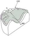
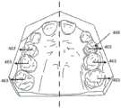
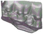
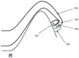
图1示出腭扩张器的一个示例,该腭扩张器包括封闭附件,所述封闭附件可以帮助在口腔内保持。Figure 1 shows an example of a palate dilator that includes a closed appendage that can aid in retention within the oral cavity.
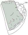
图1A-图1G示出腭扩张器的示例,该腭扩张器可以是用于扩张患者的腭的一系列腭扩张器的一部分。图1A是腭扩张器的示例的底侧(面向舌头的一侧(tongue-facingside))的前视立体图,被示出为附接在患者的上牙弓的模型上。图1B是腭扩张器的示例的后视立体图;虚线163示出腭扩张器的中线。图1C是腭扩张器的示例的另一个后视立体图。图1D是图1A的腭扩张器的示例的前侧视立体图。图1E是腭扩张器的示例的侧视立体图。图1F是腭扩张器的示例的另一个后视立体图。图1G是腭扩张器示例的俯视立体图,示出牙齿接收腔和面向腭的顶表面。1A-1G illustrate an example of a palate dilator, which may be part of a series of palate dilators for dilating a patient's palate. 1A is a front perspective view of the underside (tongue-facing side) of an example palatal expander, shown attached to a cast of a patient's upper dental arch. Figure IB is a rear perspective view of an example of a palatal dilator; dashed
图2A-图2C示出用于扩张患者的腭的系统的示例,该系统包括附件模板(在图2A中以立体图示出)、渐进式腭扩张器的系列(在图2B中示出)和被动保持架(例如,图2C中所示的保持器)。Figures 2A-2C show an example of a system for dilating a patient's palate comprising an accessory template (shown in perspective in Figure 2A), a series of progressive palatal dilators (shown in Figure 2B) and a passive cage (eg, the cage shown in Figure 2C).
图3A示出使用本文所述的腭扩张器治疗患者以扩张患者的腭的方法的示例。3A illustrates an example of a method of treating a patient using the palate expander described herein to expand the patient's palate.
图3B示出用于形成腭扩张器的示例性方法。Figure 3B illustrates an exemplary method for forming a palatal expander.
图4A示出可以施加到患者的腭以扩张腭、制动和分离腭中线骨缝(例如,中间腭骨缝等)的平移力(箭头)。图4B示出一系列示例腭扩张器,其被构造成逐渐扩张骨缝(例如,图4B中所示的扩张器可以是从例如8个或更多个扩张器的整个序列中取得的示例,并且不一定代表三个直接顺序的扩张器)。FIG. 4A illustrates translational forces (arrows) that may be applied to a patient's palate to expand the palate, immobilize, and separate palatal midline sutures (eg, midpalatine sutures, etc.). Figure 4B shows a series of example palatal dilators configured to progressively dilate the suture (e.g., the dilator shown in Figure 4B may be an example taken from an entire sequence of, for example, 8 or more dilators, and does not necessarily represent three dilators in immediate order).
图4C示出腭扩张器的示例,其中腭区域的一部分已从前部区域移除;类似地,可以例如从后部区域移除设备的其他区域。替代地或附加地,这些设备中的任一个可以在其他区域中(包括在中心区域中)具有孔切口。该示例也示出沿着腭扩张器的中线延伸的破坏区域。Fig. 4C shows an example of a palatal expander where part of the palatal region has been removed from the anterior region; similarly, other regions of the device may be removed, for example from the posterior region. Alternatively or additionally, any of these devices may have hole cutouts in other areas, including in the central area. This example also shows a zone of disruption extending along the midline of the palatal dilator.
图4D示出包括破坏区域的腭扩张器的另一示例,被示出为沿着第一牙齿接合区域的咬合面延伸。还示出了拉力。Fig. 4D shows another example of a palatal expander including a disrupted region, shown extending along the occlusal surface of the first tooth-engaging region. Pulling forces are also shown.
图4E示出包括破坏区域的腭扩张器的另一示例,其中该破坏区域是线或通道,该线或通道不是直的,而是在前部到后部方向上延伸穿过第一牙齿接合区域的咬合侧。Figure 4E shows another example of a palatal dilator including a disrupted area that is a line or channel that is not straight but extends across the first tooth engagement in the anterior to posterior direction The occlusal side of the area.
图4F示出包括破坏区域的腭扩张器的另一示例,该破坏区域在前部到后部方向上延伸穿过第一牙齿接合区域的颊侧。FIG. 4F shows another example of a palatal expander including a disrupted region extending in an anterior-to-posterior direction across the buccal side of the first tooth-engaging region.
图4G示出包括破坏区域的腭扩张器的另一示例,该破坏区域沿前部到后部方向在第一牙齿接合区域的颊侧与咬合侧之间的边界上延伸。FIG. 4G shows another example of a palatal expander including a disrupted region extending in an anterior-to-posterior direction on the boundary between the buccal and occlusal sides of the first tooth-engaging region.
图5示出可以在预定位置与腭扩张器配合的牙齿上的附件的示例;在该示例中,在治疗期间可以使用四个附件(两侧各有两个)来将每个腭扩张器固定到牙齿。Figure 5 shows an example of an attachment on a tooth that can mate with a palatal expander in a predetermined position; in this example, four attachments (two on each side) can be used to hold each palate expander in place during treatment to the teeth.
图6A示出腭扩张器的示例,其包括:脱离区域(例如,移除手柄或凸片)和从侧向边缘(例如,颊侧的边缘)朝向咬合面延伸的两个或更多个侧向铰接区域(例如,狭槽、切口、狭缝、弯曲区域(flex region,屈曲区域)等),其可用于帮助将设备从受试者的口腔中移除;以及在牙齿接合区域的颊侧上从前部到后部方向部分地延伸穿过的破坏区域。Figure 6A shows an example of a palatal expander that includes a disengagement region (e.g., removal handle or tab) and two or more sides extending from a lateral edge (e.g., buccal edge) toward the occlusal surface. Towards hinged areas (e.g., slots, cutouts, slits, flex regions, etc.), which can be used to help remove the device from the subject's mouth; and buccally in areas where the teeth engage The damage zone extending partly across in the anterior to posterior direction.
图6B示出通过腭扩张器的一部分的截面,该腭扩张器被构造成包括脱离区域,在该脱离区域中腭扩张器的外(例如,颊的)边缘形成有间隙,该间隙将其与牙齿和/或牙龈分开,并且其尺寸和构造被设定为使得患者的指甲和/或移除装置可以插入以将设备从牙齿上拉下来,包括从牙齿上的附件上拉下来。Figure 6B shows a section through a portion of a palate dilator configured to include a breakaway region in which the outer (e.g., buccal) edge of the palate dilator forms a gap that separates it from the palate dilator. The teeth and/or gums are spaced apart and sized and configured such that the patient's nails and/or removal device can be inserted to pull the device off the teeth, including from attachments on the teeth.
图7A示出在腭扩张器外壳设备的颊侧上具有脱离区域的腭扩张器的一个示例。在图7A中,示出两个脱离区域,并且每个脱离区域包括突出的支点区域。Figure 7A shows an example of a palate dilator with a breakaway area on the buccal side of the palate dilator housing device. In Fig. 7A, two disengagement regions are shown, and each disengagement region includes a protruding fulcrum region.
图7B示出腭扩张器的另一示例,其具有腭扩张器外壳的颊侧的底部边缘区域,该底部边缘区域被构造成脱离区域。FIG. 7B shows a further example of a palatal dilator with a buccal bottom edge region of the palate dilator housing, which is designed as a breakaway region.
图7C示出腭扩张器的另一示例,其具有被构造成脱离区域的底部边缘区域,被构造成在腭扩张器的每侧提供把手。7C shows another example of a palatal dilator having a bottom edge region configured as a breakaway region configured to provide a handle on each side of the palatal dilator.
图7D示出图7C的把手区域的放大仰视图。Figure 7D shows an enlarged bottom view of the handle area of Figure 7C.
图7E示出说明图7C-图7D中所示的装置的脱离区域(把手)之一的操作的轮廓图。Figure 7E shows a profile diagram illustrating the operation of one of the disengagement regions (handles) of the device shown in Figures 7C-7D.
图7F示出图7C的把手区域的放大俯视图。Figure 7F shows an enlarged top view of the handle area of Figure 7C.
图8示出使用移除工具将腭扩张器从患者的上牙弓脱离的示例。该工具可以施加拉力,以使腭扩张器外壳设备的破坏区域沿着该破坏区域断裂或弯曲,并使腭扩张器外壳设备与患者的第一组或第二组牙齿脱开,包括使腭扩张器从患者牙齿上的一个或多个附件分离。Figure 8 shows an example of disengagement of the palatal expander from the patient's upper dental arch using a removal tool. The tool may apply pulling force to fracture or bend the fractured region of the palatal expander housing device along the disrupted region and disengage the palatal expander housing device from the patient's first or second set of teeth, including expanding the palate The appliance is detached from one or more attachments on the patient's teeth.
图9示出可用于移除腭扩张器的工具的示例,其包括近侧手柄区域和远侧腭扩张器接合区域。Figure 9 shows an example of a tool that may be used to remove a palatal dilator including a proximal handle region and a distal palatal dilator engagement region.
图10A示出移除工具的另一示例,其被构造成施加拉力并从患者的牙弓上移除腭扩张器。在图10A中,移除工具被构造成环。环可以用在任何一只手上(例如,可以是可反转的)。FIG. 10A illustrates another example of a removal tool configured to apply tension and remove a palatal expander from a patient's dental arch. In Fig. 10A, the removal tool is configured as a ring. The ring can be used on either hand (eg, can be reversible).
图10B示出图10A的工具的放大视图。Figure 10B shows an enlarged view of the tool of Figure 10A.
图10C示出图10A-图10B中的工具的操作。该工具在外表面上包括一个平坦的区域1009,该区域可用作手指放置部,并有助于使用支点区域,例如,当通过扭转或旋转(如图所示)施加拉力以移除腭扩张器器具时,保持环稳固,以防止环绕着手指旋转。Figure 10C illustrates the operation of the tool in Figures 10A-10B. The tool includes a
图11A-图11D示出用于通过施加拉力来移除腭扩张器的另一示例。在图11A中,工具以前视图示出。图11B示出图11A的工具的侧视图。图11C是使用图11A-图11B的工具来施加拉力以移除佩戴在患者的上牙弓上的腭扩张器的方法的示例。图11D示出正用于从患者移除腭扩张器的工具的另一视图。11A-11D show another example for removing a palatal dilator by applying a pulling force. In FIG. 11A the tool is shown in front view. Figure 11B shows a side view of the tool of Figure 11A. 11C is an example of a method of using the tool of FIGS. 11A-11B to apply pulling force to remove a palatal expander worn on a patient's upper dental arch. Figure 1 ID shows another view of the tool being used to remove the palatal dilator from the patient.
图12示出用于通过施加拉力来移除腭扩张器的工具的另一示例。在图12中,工具包括由工具上的控制器(例如,该示例中的挤压把手)驱动的支撑臂和拉臂。Fig. 12 shows another example of a tool for removing a palatal dilator by applying a pulling force. In Figure 12, the tool includes a support arm and a pull arm actuated by a controller on the tool (eg, a squeeze handle in this example).
图13A-图13G示出移除工具的示例,其用于施加拉力来移除腭扩张器。这些示例中的每一个都包括工具上的支撑(例如,支点)臂,所述支撑臂可以抵靠腭扩张器支承,以帮助施加拉(移除)力。13A-13G illustrate an example of a removal tool for applying pulling force to remove a palatal dilator. Each of these examples includes a support (eg, fulcrum) arm on the tool that can bear against the palatal expander to help apply the pulling (removal) force.
图14A示出移除工具的另一示例,其用于施加力以移除如本文所述的腭扩张器。Fig. 14A shows another example of a removal tool for applying force to remove a palatal dilator as described herein.
图14B示出移除工具的另一示例,其用于施加力以移除如本文所述的腭扩张器。14B shows another example of a removal tool for applying force to remove a palatal dilator as described herein.
图14C是移除工具的另一示例,其用于施加力以移除腭扩张器;在图14C中,该工具可用于患者的右侧或左侧。Fig. 14C is another example of a removal tool used to apply force to remove a palatal dilator; in Fig. 14C, the tool can be used on the right or left side of the patient.
图15A-图15C示出将腭扩张器2100插入患者牙齿中的方法的示例,包括将所述装置放置在患者口腔中的上牙弓上(图15A),并向下咬在腭扩张器设备上(图15B和图15C)以安置所述装置并将所述装置固定在牙齿上(在一些例子中,包括固定在附件上)。15A-15C illustrate an example of a method of inserting a
图16A-图16C示出包括脱离区域的示例性腭扩张器设备的移除,通过将指甲插入到脱离区域中(图16A),从牙齿沿颊侧拉离(图16B)以从任一附件脱开,然后向下拉动(图16C)以从牙齿上移除所述设备。Figures 16A-16C illustrate the removal of an exemplary palatal dilator device including a breakaway area by inserting a fingernail into the breakaway zone (Figure 16A), pulling buccally away from the tooth (Figure 16B) to disengage from either attachment Disengage, then pull down (FIG. 16C) to remove the device from the tooth.
图17A和图17B示出用于移除腭扩张器的示例性工具的另一变型的操作,所述工具被构造成从所述设备的腭区域施加力以从患者的牙齿上移除腭扩张器。该工具可以施加力以使腭扩张器外壳设备的破坏区域沿着所述破坏区域(例如,在腭扩张器的腭区域中)断裂或弯曲,以使腭扩张器外壳设备从患者的牙齿脱开。17A and 17B illustrate the operation of another variation of an exemplary tool for removing a palatal expander configured to apply force from the palatal region of the device to remove the palatal expander from the patient's teeth. device. The tool can apply a force to fracture or bend the fractured region of the palatal expander housing device along the disrupted region (e.g., in the palatal region of the palatal expander) to disengage the palatal expander housing device from the patient's teeth .
图18A和图18B示出用于移除腭扩张器的示例性工具的另一变型的操作,所述工具被构造成从所述设备的腭区域施加力以从患者的牙齿上移除腭扩张器。该工具可施加力以使腭扩张器外壳设备的破坏区域沿着所述破坏区域(例如,在腭扩张器的腭区域中)断裂或弯曲,以使腭扩张器外壳设备从患者的牙齿脱开。18A and 18B illustrate the operation of another variation of an exemplary tool for removing a palatal expander configured to apply force from the palatal region of the device to remove the palatal expander from the patient's teeth. device. The tool can apply a force to fracture or bend the fractured region of the palatal expander housing device along the disrupted region (e.g., in the palatal region of the palatal expander) to disengage the palatal expander housing device from the patient's teeth .
图19A-图19B示出腭扩张器系统的示例,所述系统具有锁,易于将腭扩张器从牙齿移出。Figures 19A-19B show an example of a palatal expander system with a lock for easy removal of the palatal expander from the teeth.
图20A示出腭扩张器,其具有弹性钩接和移出(elastic hooking anddislodging),易于放置和释放。Figure 20A shows a palatal dilator with elastic hooking and dislodging for easy placement and release.
图20B示出了腭扩张器,具有与支架接合的弹性锁。Figure 20B shows a palatal dilator with a resilient lock engaged with a bracket.
图20C-图20D示出用于腭扩张器的锁的另一示例,被构造成与患者牙齿上的附件可释放地接合。20C-20D illustrate another example of a lock for a palatal expander configured to releasably engage with an attachment on a patient's teeth.
图21示出腭扩张器,其中附件的顶部和底部可以具有不同的刚度和角度,以使得保持力(retention force)和移除力可以被分别设计,以达到期望的功能和移除特征。Figure 21 shows a palatal dilator where the top and bottom of the attachment can have different stiffnesses and angles so that the retention force and removal force can be designed separately to achieve the desired function and removal characteristics.
图22A示出具有球窝关节卡扣(ball and socket joint snap)的腭扩张器,其中附件是球侧,而扩张器是具有柔性突起的承窝侧。Figure 22A shows a palatal dilator with a ball and socket joint snap, where the appendage is the ball side and the dilator is the socket side with the flexible protrusion.
图22B示出具有圆柱形附件的腭扩张器,其中dim A侧是具有卡扣的附件,而dim B是具有圆柱形狭槽的扩张器侧。Figure 22B shows a palatal dilator with a cylindrical appendage, where the dim A side is the appendage with snaps, and dim B is the dilator side with the cylindrical slot.
图22C和图22D示出腭扩张器,其具有用于延长卡扣配合(snap fit,钳合)的叉齿。Figures 22C and 22D show a palatal expander with prongs for extended snap fit (snap fit).
图22E和图22F示出用于搭扣(snap-on)配合的腭扩张器。Figures 22E and 22F show a palatal expander for a snap-on fit.
图23示出可用于腭扩张器的可伸缩笔机构,以与牙齿接合和移出。Figure 23 shows a retractable pen mechanism that can be used with a palatal expander to engage and remove teeth.
图24示出了与牙齿接合的腭扩张器的剖视图和侧视图,其中使用螺纹螺母和螺栓来接合或移出腭扩张器。Figure 24 shows a cross-sectional and side view of a palatal expander engaged with a tooth, using threaded nuts and bolts to engage or remove the palatal expander.
具体实施方式Detailed ways
本文描述的腭扩张设备(装置和系统,包括腭扩张器)被构造成扩张患者的腭,并且通常被构造成由患者或患者的护理者(例如,父母、监护人等)移除和/或插入。患者可以佩戴一系列扩张器来随着时间的推移而扩张患者的腭。The palate expansion devices (devices and systems, including palate expanders) described herein are configured to expand the patient's palate, and are generally configured to be removed and/or inserted by the patient or the patient's caregiver (e.g., parent, guardian, etc.) . Patients may wear a series of dilators to expand the patient's palate over time.
本发明的腭扩张器的各种属性和特性在本文中大体上描述,并参考具体的实例进行描述。这些属性和特性中的任一个,包括特征的布置,可以合并到腭扩张器中。这些腭扩张器可交换地称为腭扩张外壳设备,其可被构造成在患者口腔内施加力以扩张患者的上颌骨(maxilla)。患者可以是任何合适的患者,尤其是(但不限于)7至9岁的儿童,例如,第一永久性臼齿长出后的儿童。这些设备可以用于将患者的腭扩张4至12mm或更多。Various attributes and characteristics of the palatal dilator of the present invention are described generally herein and with reference to specific examples. Any of these attributes and characteristics, including the arrangement of features, can be incorporated into the palatal expander. These palate expanders, interchangeably referred to as palate expansion housing devices, may be configured to apply force within the patient's oral cavity to expand the patient's maxilla. The patient may be any suitable patient, especially (but not limited to) a child aged 7 to 9 years, for example, a child after the first permanent molars have erupted. These devices can be used to dilate a patient's palate by 4 to 12 mm or more.
在使用中,该系列腭扩张器可以由患者(或护理者,例如,父母)施加和/或移除,并且可以适于牢固地附接到患者的牙齿上,具有足够的强度来移动患者的腭,同时可以在没有过大的力或难度的情况下移除(例如,使用手指和/或工具移除)。该设备可以附在患者的上牙弓两侧的牙齿上的两颗、三颗或更多颗,例如,附接到最后三颗牙齿上(例如,附在第一永久性臼齿和第一、第二乳臼齿上和/或附接到第一永久性臼齿和第一、第二乳臼齿)。通常,本文描述的设备产生足够的力来打开患者的骨缝,例如,施加8N到120N之间(或大于8N、大于9N、大于10N、大于20N、大于30N、大于40N、大于50N、大于60N等)的力抵靠腭的两侧和/或牙齿的舌侧,但移除所需的力要小得多。In use, the series of palatal expanders can be applied and/or removed by the patient (or a caregiver, for example, a parent), and can be adapted to be firmly attached to the patient's teeth, with sufficient strength to move the patient's teeth. The palate, while being removable without undue force or difficulty (eg, using fingers and/or tools). The device may be attached to two, three, or more teeth on either side of the patient's upper dental arch, for example, to the last three teeth (e.g., to the first permanent molar and the first, Second deciduous molars on and/or attached to first permanent molars and first and second deciduous molars). Typically, the devices described herein generate sufficient force to open the patient's suture, for example, applying between 8N and 120N (or greater than 8N, greater than 9N, greater than 10N, greater than 20N, greater than 30N, greater than 40N, greater than 50N, greater than 60N etc.) against the sides of the palate and/or the lingual sides of the teeth, but removal requires much less force.
在本文描述的任何设备和方法中,所述设备可以被构造成使得其在与结合到患者牙齿上的附件连接或不连接的情况下都可以牢固地附接到患者牙齿上,同时仍然可以被患者和/或护理者轻易地移除。具体地,本文描述的任何腭扩张器可以包括破坏区域,该破坏区域被构造成当施加移除(例如,拉)力时优先地和可控地弯曲或断裂;所述拉力可导致腭扩张器外壳设备的破坏区域沿着破坏区域断裂或弯曲,并且使腭扩张器外壳设备从患者的第一或第二组牙齿脱开。In any of the devices and methods described herein, the device can be configured such that it can be securely attached to the patient's teeth, with or without attachments that are bonded to the patient's teeth, while still being accessible. Easily removed by the patient and/or caregiver. In particular, any of the palatal dilators described herein may include a failure region configured to preferentially and controllably bend or break when a removal (e.g., pulling) force is applied; the pulling force may cause the palatal dilator to The failure region of the housing device breaks or bends along the failure region and dislodges the palatal expander housing device from the patient's first or second set of teeth.
本文描述的任何腭扩张器可以包括附件,所述附件通过接合到患者牙齿上的附件而锁定到患者牙齿上。在一些变型中,腭扩张器可以(例如,在侧边,诸如在腭扩张器的颊侧上)具有锁,所述锁与结合到患者牙齿上的附件接合,以防止腭扩张器被移除,直至所述锁被脱开。在一些变型中,可以通过手动移动、弯曲、拉动、推动、移位或以其他方式操作释放控制器来脱开锁。释放控制器可以是闩锁、杠杆、开关、凸片、臂、卡扣等。锁和释放控制器可以彼此机械地接合和/或与患者牙齿上的附件接合。可替代地或另外地,锁、释放和/或附件可以彼此磁性地接合。Any of the palatal expanders described herein may include attachments that lock to the patient's teeth via attachments that engage the patient's teeth. In some variations, the palatal dilator may have a lock (e.g., on a side, such as on the buccal side of the palatal dilator) that engages with an attachment bonded to the patient's teeth to prevent the palatal dilator from being removed , until the lock is disengaged. In some variations, the lock may be disengaged by manually moving, bending, pulling, pushing, displacing, or otherwise manipulating the release control. The release control can be a latch, lever, switch, tab, arm, snap, etc. The lock and release controls can be mechanically engaged with each other and/or with attachments on the patient's teeth. Alternatively or additionally, the lock, release and/or attachment may be magnetically engaged with each other.
本文描述的任何设备可以被构造成使得腭区域的上凸表面与患者的腭(例如,包括存在于患者的特定解剖结构中的任何沟槽、脊、槽等)匹配。上凸表面可以与患者的腭匹配,但是可以被构造成与患者的腭分开或偏离例如0.5mm或更多,特别是位于更中心(例如,与腭中线骨缝相对)的区域。在一些变型中,该设备可以从患者的腭偏离,并且力可以主要施加在牙齿(例如,臼齿)的舌侧上;可替代地或另外地,该设备可以被构造成在臼齿上方对腭的侧面区域施加力;在这种情况下,腭区域的上凸表面可以被构造成具有负偏离,例如,在佩戴时可以推压腭。Any of the devices described herein can be configured such that the convex surface of the palatal region matches the patient's palate (eg, including any grooves, ridges, grooves, etc. that exist in the patient's particular anatomy). The convex surface may match the patient's palate, but may be configured to be separated or offset from the patient's palate, eg, by 0.5 mm or more, particularly in more central (eg, opposite the palatal midline suture) regions. In some variations, the device may be offset from the patient's palate, and the force may be applied primarily on the lingual side of the teeth (e.g., molars); alternatively or additionally, the device may be configured to oppose the palate over the molars. The lateral regions exert force; in this case, the convex surface of the palatal region can be configured with a negative offset, eg, to push against the palate when worn.
本文描述的腭扩张器可以(例如,通过增材(additive),例如,3D打印技术等)由单块材料形成,或者它们可以部分地形成,例如,通过分层、热固化等形成。该设备(例如,装置、系统等)可以具有均匀或可变的厚度。例如,腭区域在更前部区域(例如,前半部分)中与在更后部区域(例如,后半部分)中相比可以更薄。或者,设备的后半部分可以比前半部分更薄。后部部分可以向内(例如,朝向前部区域)弯曲,或者可以在后端中包括切口区域。The palatal expanders described herein may be formed (eg, by additive, eg, 3D printing techniques, etc.) from a single piece of material, or they may be formed in parts, eg, by layering, heat curing, or the like. The device (eg, device, system, etc.) can have a uniform or variable thickness. For example, the palatal region may be thinner in a more anterior region (eg, front half) than in a more posterior region (eg, posterior half). Alternatively, the rear half of the device could be thinner than the front half. The rear portion may curve inwardly (eg, toward the front region), or may include a cutout region in the rear end.
可以在制造过程中控制和选择设备(例如,扩张器)的形状,并因此控制和选择在佩戴时由设备施加的负载。提供数字规划过程可能是特别有利的,在该过程中,患者上颌(例如,牙齿、腭和牙龈)以及在一些情况下受试者的下颌(例如,牙齿和/或牙龈)的数字模型可以被修改,以规划在患者初始解剖结构(initial anatomy)与扩张构造(其中描述了最终的扩张构造)之间变形的一系列扩张器。The shape of the device (eg, dilator), and thus the load exerted by the device when worn, can be controlled and selected during the manufacturing process. It may be particularly advantageous to provide a digital planning process in which a digital model of the patient's upper jaw (e.g., teeth, palate, and gums) and, in some cases, the subject's lower jaw (e.g., teeth and/or gums) can be created. Modifications to plan a series of dilators deformed between the patient's initial anatomy and an expanded configuration in which the final expanded configuration is described.
本文描述的腭扩张器可包括用于接合患者上颌中的至少一部分牙齿(特别是臼齿和/或前臼齿)的牙齿接合区域,以及在所述牙齿接合区域之间延伸的腭区域,所述腭区域被构造成,当患者佩戴该装置时,腭区域被定位成与患者的腭相邻且相对。例如,图1和图1A-图1G示出腭扩张器100、150的示例,该腭扩张器包括在装置的两侧上通过腭区域105连接的一对牙齿接合区域103、103’。腭扩张器还可以包括一个或多个附接区域(例如,附件联接区域)107,其可以与在装置的任一侧上结合到患者牙齿的一对附件(例如,附接连接器)(在患者牙齿的颊侧上;在图1中仅可见一对)联接。在本文中,附接连接器也可被称为连接器、销、附件等,并且可以在允许其联接(例如,可移除地联接)到扩张器上的附接区域的位置处固定到牙齿。作为佩戴一系列扩张器之前的初始步骤的一部分,可以将附接连接器结合(胶合等)到牙齿上。在图1中,示出了腭扩张器的腭区域的底部凹表面108;相对的表面是顶部凸表面。图1还示出腭扩张器的破坏区域167的一个示例,在该示例中,破坏区域被构造为通过牙齿接合区域103中之一的咬合侧从前部到后部地延伸的线。尽管在图1中,破坏区域呈直线延伸,但是它可以具有任何适当的厚度,并且包含材料强度比相邻的周围区域小的区域。可以通过使用不同的材料和/或不同的厚度和/或包含间隙或开口来实现这种更低的强度。下面提供了破坏区域的其他示例。A palatal expander as described herein may comprise a tooth engaging region for engaging at least a portion of teeth in the patient's upper jaw, particularly molars and/or premolars, and a palatal region extending between said tooth engaging region, said palate The region is configured such that when the device is worn by the patient, the palatal region is positioned adjacent to and opposite the palate of the patient. For example, Figures 1 and 1A-1G illustrate examples of
牙齿接合区域可以由与腭区域相同的材料形成,或者它们可以包括不同的材料。在一些变型中,可以在腭区域与咬合区域之间的交界(junction)、咬合区域与颊区域之间的交界等处形成破坏区域。咬合区域与腭区域的厚度可能不同或相同。特别地,腭区域可以比牙齿接合区域厚。牙齿接合区域的厚度沿着装置的侧面(例如,颊侧和/或舌侧)可以更厚,并且在牙齿接合区域的顶部的全部或一部分上更薄(或从牙齿接合区域的顶部的全部或一部分上被移除)。腭区域可以具有不均匀的厚度。例如,腭扩张器可以在装置的中线附近更厚。任何腭扩张器可包括肋或其他支撑件(例如,在牙齿接合区域之间和/或垂直于牙齿接合区域横向地延伸)。这些肋可以由与腭区域其他部分相同的材料形成(例如,但是更厚和/或被成形为具有圆柱形横截面轮廓)。The tooth-engaging regions may be formed from the same material as the palatal region, or they may comprise different materials. In some variations, the disrupted region may be formed at the junction between the palatal region and the occlusal region, the junction between the occlusal region and the buccal region, or the like. The thickness of the occlusal and palatal regions may be different or the same. In particular, the palatal region may be thicker than the tooth juncture region. The thickness of the tooth-engaging area can be thicker along the sides of the device (e.g., buccal and/or lingual) and thinner over all or a portion of the top of the tooth-engaging area (or from all or part of the top of the tooth-engaging area). partially removed). The palatal region can have uneven thickness. For example, the palatal dilator can be thicker near the midline of the device. Any palatal expander may include ribs or other supports (eg, extending laterally between and/or perpendicular to tooth engagement regions). These ribs may be formed from the same material (eg, but thicker and/or shaped to have a cylindrical cross-sectional profile) as the rest of the palatal region.
牙齿接合区域的内(腔)部分通常被构造成符合患者牙齿的外轮廓,并且直接抵靠牙齿和/或牙龈的一部分(或避开牙龈)以向其施加力。当患者佩戴时与腭相邻定位的腭区域的上表面可以被轮廓化以与患者的腭的实际或预测形状相匹配。如上所述,当佩戴时,腭区域的全部或大部分可以与患者的腭分开或间隔开,这样可以增强舒适度并最小化对发音的破坏。The inner (cavity) portion of the tooth-engaging area is typically configured to conform to the outer contours of the patient's teeth, and to apply force directly against the teeth and/or a portion of the gums (or away from the gums). The upper surface of the palate region positioned adjacent to the palate when worn by the patient may be contoured to match the actual or predicted shape of the patient's palate. As noted above, when worn, all or most of the palate region can be separated or spaced from the patient's palate, which can enhance comfort and minimize disruption to articulation.
在一些变型中,在装置的任一侧上在相对的牙齿接合区域之间延伸的腭区域的一部分(例如,腭区域的在牙齿接合区域之间延伸大约z%的距离的一部分,其中z大于约30%、40%、50%、60%、70%、80%、90%等)可以是平的或直的,而不是弯曲的,因此它不一定遵循患者的口腔的轮廓。该部分可以是一个或多个横向肋、支柱或支撑件,或者它可以是平板。这种平坦或直的部分可以提供增加的力。替代地或附加地,腭区域(例如,一个或多个肋、板等)可以弯曲成弧形(该弧形类似于患者的腭的弧形),但是可以具有比患者的腭更大的曲率半径(看起来为一个更浅的凹表面)。In some variations, a portion of the palatal region extending between opposing tooth engagement regions on either side of the device (e.g., a portion of the palatal region extending about z% of the distance between the tooth engagement regions, where z is greater than About 30%, 40%, 50%, 60%, 70%, 80%, 90%, etc.) may be flat or straight, rather than curved, so it does not necessarily follow the contours of the patient's mouth. The portion may be one or more transverse ribs, struts or supports, or it may be a flat plate. Such flat or straight sections can provide increased force. Alternatively or additionally, the palatal region (e.g., one or more ribs, plates, etc.) may be curved in an arc similar to that of the patient's palate, but may have a greater curvature than the patient's palate Radius (looks like a shallower concave surface).
本文描述的任何腭扩张器可包括一个或多个附接区域或部位(在本文中也称为附接开口、附接连接器等),用于联接到患者牙齿上的附接连接器。特别地,在装置的每侧上使用一个或多个(例如,一对)附接区域可能是有帮助的。此外,附接部位可以优选地是穿过扩张器的开口。正畸扩张器上的开放结构(附接部位)可以与位于牙齿上的附件(附接连接器)相互作用,以改善器具的整体保持,并且在一些情况下可以用于产生牙齿对准的有利的力特征,包括限制或防止牙齿随着腭扩张而向颊部动摇(rolling)。特别地,当作为用于快速(例如,阶段1)腭扩张的直接制造(例如,3D打印)装置的一部分而被包括时,这些特征可能是有帮助的。此外,尽管附接连接器通常结合到一个或多个牙齿并且突出到扩张器上的互补开口或腔中,但是在一些或全部中该构造可以是相反的;例如,突出的附接连接器可以是扩张器的一部分,其可以插入于结合到使用者牙齿的开口/腔中。在一些变型中,可以使用以多种材料(包括更具弹性和/或更低强度的材料)进行打印的3D打印机来直接打印本文描述的设备,包括破坏区域和/或锁。Any of the palatal expanders described herein may include one or more attachment regions or locations (also referred to herein as attachment openings, attachment connectors, etc.) for coupling to attachment connectors on the patient's teeth. In particular, it may be helpful to use one or more (eg, a pair) of attachment areas on each side of the device. Furthermore, the attachment site may preferably be an opening through the dilator. Open structures (attachment sites) on orthodontic expanders can interact with appendages (attachment connectors) located on the teeth to improve overall retention of the appliance and in some cases can be used to create teeth alignment benefits force characteristics, including limiting or preventing the teeth from rolling toward the cheek as the palate expands. In particular, these features may be helpful when included as part of a direct-to-manufacture (eg, 3D printed) device for rapid (eg, stage 1) palatal expansion. Furthermore, while the attachment connectors are typically coupled to one or more teeth and protrude into complementary openings or cavities on the dilator, in some or all this configuration may be reversed; for example, the protruding attachment connectors may is the part of the dilator that can be inserted into the opening/cavity that joins the user's teeth. In some variations, a 3D printer that prints in a variety of materials, including more elastic and/or lower strength materials, may be used to directly print the devices described herein, including the failure areas and/or locks.
可以使用任何合适的附接区域,并且特别地,可以使用任何合适的尺寸和/或形状。如前所述,附接区域可以是器具上的开放结构,其可以改善器具在附件上的保持,并且可能包括用于牙齿对准的力特征。例如,附接区域可以包括穿过扩张器的圆形、椭圆形、正方形、矩形、三角形等开口(例如,在扩张器的牙齿恢复区域的侧面,例如颊侧)。附接区域可以相对于附接连接器键接;通常,附接连接器可以被构造成以一个或特定取向与附接区域配合。Any suitable attachment area may be used, and in particular any suitable size and/or shape may be used. As previously mentioned, the attachment area may be an open structure on the appliance that may improve retention of the appliance on the attachment, and may include force features for tooth alignment. For example, the attachment area may include a circular, oval, square, rectangular, triangular, etc. opening through the dilator (eg, on the side of the dilator's tooth restoration area, such as the buccal side). The attachment area may be keyed relative to the attachment connector; generally, the attachment connector may be configured to mate with the attachment area in one or a particular orientation.
图1A-图1G中从不同视角示出了示例性腭扩张器150。该示例还可以包括破坏区域(在图1A-图1G中不可见),以允许优先断裂和/或弯曲。这些或类似的腭扩张器可以单独或共同地包括本文中描述的任一特征。在该示例中,腭扩张器被构造成是可移除的,例如,是患者可移除的(使用或不使用移除工具),其可由任何合适的材料(包括例如生物相容性的尼龙材料)形成。可以使用一系列腭扩张器并逐步分级(staged),以扩张患者的腭。特别地,本文描述的方法和设备可以被构造为用于治疗儿童和年轻人。腭扩张器可以被构造成为了患者舒适性而使得横腭弓形区域153平衡负载偏差。例如,横向力463可分布在每侧的三颗后牙466上,如图4A所示,和或分布在腭的侧面上。为了结构完整性和患者舒适性,可以最优化咬合面154的厚度。腭扩张器设备可以包括多个附件(在图1A-图1G中不可见)。附件可以被构造为允许器具容易地插入和保持。如本文将更详细地描述的,腭扩张器还可以包括一个或多个移除特征,以允许患者在附接设备后移除设备。An exemplary
如上所述,在以下附加细节中,由设备施加的用于扩张患者的腭的力可以均匀地沿着前后方向(通常在中线的两侧对称地)或沿着前后方向在不同区域处被施加到牙齿(例如,D、E或6牙齿的舌侧)和/或腭,特别是腭的侧面(在牙龈线上方但在中线下方)。As noted above, in additional detail below, the force applied by the device to expand the patient's palate may be applied uniformly in the anterior-posterior direction (usually symmetrically on either side of the midline) or at different regions in the anterior-posterior direction. To the teeth (eg, lingual side of teeth D, E, or 6) and/or the palate, especially the lateral side of the palate (above the gum line but below the midline).
在本文描述的任何腭扩张器中,可以包括穿过腭扩张器形成的开口或孔。例如,在一些变型中,可以去除腭扩张器的否则会覆盖患者牙齿的咬合面的区域。例如,允许更自然的咬合。在一些变型中,腭区域的在上牙弓的相对侧(例如,设备的相对的牙齿接收部分)之间延伸的前部(前区域)可以被移除或向内弯曲,以避免干扰发音。可替代地或另外地,腭扩张器的后(poster)(例如,背侧)端可被移除或向前弯曲,以最小化或减少引起(invoking)呕吐反射。在这些变型中的任一个中,还可以附加地或替代地调节厚度。例如,腭扩张器的后部区域(例如,背侧10%、20%、30%等)中的厚度可以比更前部区域中的厚度更薄。In any of the palate dilators described herein, an opening or hole formed through the palate dilator may be included. For example, in some variations, regions of the palatal expander that would otherwise cover the occlusal surfaces of the patient's teeth may be removed. For example, allowing for a more natural bite. In some variations, the front portion of the palatal region (anterior region) extending between opposite sides of the upper arch (eg, opposing tooth-receiving portions of the device) may be removed or curved inward to avoid interfering with articulation. Alternatively or additionally, the poster (eg, dorsal) end of the palatal dilator may be removed or bent forward to minimize or reduce the invoking gag reflex. In any of these variations, it is also possible to additionally or alternatively adjust the thickness. For example, the thickness in the posterior region (eg, dorsal 10%, 20%, 30%, etc.) of the palatal dilator may be thinner than in the more anterior region.
本文描述的设备可以被构造为一个系统,其包括:附件和用于将附件定位在牙齿上的附件模板,逐渐扩张患者的腭的一系列腭扩张器,以及被动保持架(例如,保持器),该被动保持架用于在该系列腭扩张器已经扩宽了腭之后佩戴。例如,图2A-图2C示出了这种系统的这些部件。图2A示出了附件模板251的示例;多个附件(图2A中未示出)可以在预定位置处附接到患者的牙齿,所述预定位置可以对应于每个腭扩张器上的接收部位的位置。图2B示出了一系列腭扩张器的示例,这些扩张器逐渐变广(例如,变宽)以逐渐扩张患者的腭。例如,上面的腭扩张器258比中间的腭扩张器259和最终的腭扩张器260窄。图2C示出了被动保持架(例如,保持器)261的示例,该被动保持架可在该系列腭扩张器已经完成患者的腭扩张之后佩戴。在该示例中,腭扩张器保持器261与序列中的最后一个腭扩张器类似或相同,尽管它可以具有不同的构造。The devices described herein can be configured as a system that includes: an attachment and an attachment template for positioning the attachment on the teeth, a series of palatal expanders that progressively expand the patient's palate, and a passive retainer (e.g., retainer) , this passive cage is intended to be worn after the palate has been widened by the series of palatal expanders. For example, Figures 2A-2C illustrate these components of such a system. Figure 2A shows an example of an
本文描述的任一示例可以被构造为包括例如:例如在牙龈边缘间隙和/或延伸部分处的脱离区域(例如,移除凸片、狭槽等)以帮助移除器具;腭扩张器识别标记(例如,扩张器识别码)等。Any of the examples described herein can be configured to include, for example: breakaway areas (e.g., removal tabs, slots, etc.) at the gingival margin spaces and/or extensions to facilitate removal of the appliance; palatal expander identification marks (e.g. dilator identification code), etc.
图5示出放置在患者牙齿上的附件的放大视图。图5示出两个附件551、552,一个位于E的(牙冠中心)臼齿上,另一个位于6的(中间尖点)臼齿区域上。附件可以被结合到牙齿上。在该示例中,使用四个附件,两侧各两个。所述附件可以与腭扩张器上的附接区域接合(例如,参见图4D-图4G中的附接区域498)。Figure 5 shows an enlarged view of an attachment placed on a patient's teeth. Figure 5 shows two
在图2B和图4B中所示的示例性主动腭扩张器中,扩张器可以被构造为用于日常佩戴(例如,23-24小时的佩戴)。在这些示例中,腭扩张器可以被构造成提供每阶段的预定量的总牙弓宽度致动(例如,约0.15mm、0.20mm、0.25mm等),这与螺旋致动扩张器类似。该系列的每个扩张器可以包括沿前后方向延伸的开口区域267、267’、267”。如前所述,该系列中的不同腭扩张器可各自包括破坏区域,但是该系列中的不同腭扩张器之间的破坏区域的位置可能不同或相同。在完成该序列后,可以向患者提供保持架或保持器(例如,图2C)。在一些变型中,保持架(例如,被动腭扩张器)包括破坏区域,该破坏区域被构造成沿着破坏区域挠曲或弯曲以使腭扩张器外壳设备从患者的牙齿脱开;或者,在一些变型中,保持架不包括破坏区域。通常,一个系列中的每个腭扩张器可以佩戴长达两周;同样地,一个保持架可以佩戴长达两周以保持装置。In the exemplary active palate dilator shown in FIGS. 2B and 4B , the dilator may be configured for daily wear (eg, 23-24 hour wear). In these examples, the palatal dilator may be configured to provide a predetermined amount of total arch width actuation per stage (eg, about 0.15 mm, 0.20 mm, 0.25 mm, etc.), similar to a helically actuated dilator. Each dilator in the series may include an
图4C-图4G示出包括一个或多个破坏区域的腭扩张器设备的示例。在图4C中,腭扩张器包括沿前部(例如,当佩戴时患者口腔的前部)到后部(例如,当佩戴时患者口腔的后部)方向延伸的破坏区域467。所述破坏区域可在设备中是可见的或不可见的。在一些变型中,破坏区域是较低强度的连续的,或者其大部分(例如,>60%、>65>、>70%、>75%、>80%、>85%、>90%等)是较低强度的连续线,或者包括较低强度袋状部的不连续区域的穿孔线,沿着设备长度的至少一部分延伸,诸如,沿着前后方向穿过牙齿接合区域中的一个(例如,沿着牙齿接合区域的咬合侧、颊侧或舌侧中的一个或多个,或在它们之间),和/或穿过腭区域(或在腭区域和牙齿接合区域之间)。在图4C中,破坏区域沿着设备的中线向下延伸,穿过腭区域的中线。4C-4G illustrate examples of palatal dilator devices including one or more disrupted regions. In FIG. 4C , the palate expander includes a disrupted
通常,本文描述的方法和设备可以避免对结合到患者牙齿上的附件施加移除力,因为该力可能会使附件断裂和/或从患者牙齿上移除,并且也可能干扰移除效果。通常,器具本身具有相当的刚性且抗弯曲,因此,弯曲可以优先发生在(一个或多个)破坏区域处。破坏区域(例如,弯曲区域)可以在器具中以一定的尺寸并在一定位置形成,从而当施加力(例如,拉力)时,器具(或器具的通常位于附件上方的区域)将在预设的方向上偏转,以使器具从附件脱开。In general, the methods and devices described herein avoid applying removal forces to attachments bonded to the patient's teeth that could fracture and/or remove the attachment from the patient's teeth and also interfere with removal. Typically, the appliance itself is fairly rigid and resistant to bending, so bending may preferentially occur at the zone(s) of failure. The zone of failure (e.g., a bending area) can be sized and positioned in the appliance so that when a force (e.g., pulling force) is applied, the appliance (or an area of the appliance generally above the attachment) will fall within a predetermined position. deflected in the direction to disengage the appliance from the accessory.
除了在预定位置处和/或通过预定的力分布而弯曲或断裂外,本文描述的破坏区域可以被构造成当器具安装在牙齿上时产生弹簧效应以帮助钩扣(clasping)牙齿。对于移除,受控断裂可以提供一种使移除更容易的方法。破坏区域的受控断裂对于一次性器具(例如,一次性使用或“一次性佩戴”的器具)可能尤其有用。在预定的力的作用下,器具将以易于移除的方式断裂,而不需要额外的力。这些设备中的任一个均可以被构造成使得所述(一个或多个)断裂边缘是防止损伤的(例如,不锐利的)和/或被构造成干净地断裂而不形成锐利的边缘和/或避免小碎片。在一些变型中,器具上的一层薄膜或涂层用于避免杂物(或碎片或颗粒)在口腔中扩散。破坏区域可被构造为这样的断裂特征,即,允许设备在施加在特定位置和/或方向的相对较小的力(例如,从颊侧施加的拉力等)下断裂。破坏区域可以被构造为断裂特征部,并且可以与合拢特征部组合,使得在较低的力阈值下,器具可以在破坏区域处弯曲,但较高的力可以使得器具可控地弯曲。在一些变型中,所述一个或多个破坏区域可以包括断裂的部分和弯曲的部分,以防止小碎块释放到口腔中。例如,大约一半的破坏区域可以断裂,而其余部分只是弯曲,从而作为单个(尽管是断裂的)块释放所述装置。In addition to bending or breaking at a predetermined location and/or through a predetermined force distribution, the break zones described herein may be configured to create a spring effect when the appliance is mounted on the tooth to help clasping the tooth. For removal, controlled fracturing can provide a way to make removal easier. Controlled rupturing of the disrupted region may be particularly useful for disposable appliances (eg, single-use or "one-time wear" appliances). Under the action of a predetermined force, the utensil will break in such a way that it can be easily removed without additional force. Any of these devices may be configured such that the fracture edge(s) are atraumatic (e.g., non-sharp) and/or configured to fracture cleanly without forming sharp edges and/or Or avoid small fragments. In some variations, a film or coating on the appliance is used to prevent debris (or debris or particles) from spreading in the oral cavity. The fracture region may be configured as a fracture feature that allows the device to fracture under relatively small forces applied at specific locations and/or directions (eg, buccally applied pulling force, etc.). The failure region can be configured as a break feature and can be combined with a closure feature such that at lower force thresholds the appliance can bend at the failure region but higher forces can cause the appliance to bend controllably. In some variations, the one or more disruption areas may include broken portions and curved portions to prevent release of small fragments into the oral cavity. For example, about half of the fractured area may fracture, while the remainder simply bends, releasing the device as a single, albeit fractured, piece.
图4C中所示的破坏区域467被示出为沿着腭扩张器的整个前后长度延伸的虚线。腭扩张器457的后区域包括切口区域455,该切口区域可以在佩戴所述设备时增强患者的舒适性,在口腔后部为舌头提供额外空间(例如,增强舒适性、防止发音问题等)。该示例中的破坏区域可以是穿孔的区域,例如,通过在破坏区域的任一侧包含比相邻区域更弱的材料强度的区段(section)或袋状部,这是因为例如它们包括空隙(例如,密度较低的区域,在一些变型中包括气穴(air pocket))。破坏区域可以由与相邻区域相同的材料形成。破坏区域可形成为包括结构特征部,例如变薄部、切口区域、通道等。在一些变型中,破坏区域由不同于与破坏区域相邻的(一个或多个)区域的材料形成。例如,破坏区域可以由比相邻区域更具柔性和/或密度更小的材料形成。The zone of
图4D示出腭扩张器中的破坏区域467’的另一示例。在图4D中破坏区域467’形成为穿过腭扩张器的牙齿接合区域的咬合侧471的通道。该通道可以是腭扩张器的轮廓的具有局部变薄的区域。较薄区域可以急剧形成(例如,具有阶梯,包括倒圆阶梯)轮廓以形成所示的通道。因此,当对腭扩张器施加拉力480时,破坏区域可以用作铰接区域,腭扩张器可以沿着该铰接区域断裂或弯曲,如下将更详细地描述。在图4D中,破坏区域沿着整个前后长度延伸;然而在其他变型中,破坏区域可能仅部分地延伸穿过腭扩张器。FIG. 4D shows another example of a disrupted region 467' in a palatal dilator. In Fig. 4D the breach region 467' is formed as a channel through the
图4E示出腭扩张器的另一示例,其示出破坏区域467”在第一牙齿接合区域的咬合部分497中沿前后方向延伸。在该示例中,破坏区域不沿直线延伸,而是以正弦曲线(例如,之字)图案延伸。可以对第一牙齿接合区域480的颊侧的底部边缘(和/或对脱离区域,如下所示)施加拉力,以使腭扩张器从牙齿脱离,包括通过使腭扩张器上的一个或多个附接区域498从结合到患者牙齿上的附件脱离。该示例中的破坏区域可以是脆弱区域,当施加足够强度的拉力时该脆弱区域会断裂。FIG. 4E shows another example of a palatal expander showing that the disrupted
图4F示出了腭扩张器457的另一示例,其具有当施加适当的拉力480”时会弯曲或断裂的破坏区域467”’。在图4F中,破坏区域位于第一牙齿接合区域的颊侧499上,沿前后方向延伸。该设备还包括一对附接区域498,所述附接区域被构造成用于保持结合到患者牙齿上的附件。在该示例中,附接区域498可以是形成在牙齿接合区域的颊侧上的腔,当设备被佩戴在牙齿上时,该腔能够保持附件。破坏区域在所述(一个或多个)附接区域上方延伸。在该示例中,所施加的侧向向外和/或向下(例如,当设备被佩戴在上牙弓上时,朝向下颌)拉动颊侧(例如,从颊侧的底部边缘或从颊侧的脱离区域)的拉力480”可允许破坏区域铰接状地弯曲或挠曲,使得颊侧的至少一部分从包括任何附件的牙齿脱开,并使设备从牙齿上移除,即使腭区域正在侧向施加力以扩张腭,另外该力可以将设备锁定在适当的位置。FIG. 4F shows another example of a
图4G中示出具有破坏区域467””的腭扩张器457的另一示例。该破坏区域467”’在施加适当的拉力480”时可弯曲或断裂。在图4F中,破坏区域位于第一牙齿接合区域的咬合侧497与颊侧499之间的过渡处,沿前后方向延伸。在该示例中,所施加的侧向向外和/或向下(例如,当设备被佩戴在上牙弓上时,朝向下颌)拉动颊侧(例如,从颊侧的底部边缘或从颊侧的脱离区域)的拉力480”’可以允许破坏区域铰接状地弯曲或挠曲,使得颊侧从包括任何附件的牙齿脱开,并允许设备从牙齿上移除。Another example of a
图3A示出用于为患者提供治疗方案以扩张患者的腭的示例性方法。所示出的第一步骤可以包括识别需要腭扩张的患者351。患者可以是儿童、青少年、年轻人或成年人。一旦识别出患者,可以选择性地对牙弓(包括腭、牙齿和至少一部分牙龈)进行数字扫描353。或者,可以对上牙弓手动建模(例如,使用牙齿印模)。当使用扫描时,可以使用任何合适的扫描仪,包括但不限于可以直接扫描牙齿、牙龈和腭的口腔内扫描仪。3A illustrates an exemplary method for providing a patient with a treatment plan to dilate the patient's palate. The first step shown may include identifying 351 a patient in need of palatal expansion. Patients can be children, adolescents, young adults or adults. Once the patient is identified, a
一旦上牙弓已经被建模(例如,被扫描、被手动建模等),就可以设计腭扩张器355。通常,这些设计可被构造成包括本文描述的任何特征,特别是破坏区域356。设计过程可以包括规划牙齿和/或腭的最终位置,以及设计中间腭扩张器以实现最终构造。设计过程可以包括提供附件在牙齿上的位置,以便提供牢固的附接以及移动牙齿,和/或防止在牙齿在扩张期间大幅倾斜。可以使用患者上牙弓的数字模型来数字化地执行设计过程。设计过程可以是自动化的或半自动化的。Once the upper arch has been modeled (eg, scanned, manually modeled, etc.), the
如上面所讨论的,在规划治疗方案(包括添加所述(一个或多个)破坏区域)时,设备可以被构造为包括破坏区域356。破坏区域可以位于设备的不同区域,以避免干扰正被施加的用以扩张受试者的腭和/或移动受试者牙齿的力。例如,在一些设备中在该系列中,破坏区域可以位于第一(例如,左)牙齿接合区域上,而在一些腭扩张器中,破坏区域可以位于第二(例如,右)牙齿接合区域和/或腭区域上,和/或位于腭区域和牙齿接合区域之间。腭扩张器可以或者可选地被构造成包括一个或多个脱离区域;在设计过程中,可以包括脱离区域(如果包括的话,则包括支点部分)的位置和尺寸。每个患者可能需要器具特征(诸如破坏区域和/或脱离区域)的定制设计;牙齿上附件的形状、尺寸和/或位置可以被构造为最好地应付患者具体的齿列和特征,因此可以相应地调整脱离特征(诸如破坏区域、附接区域、脱离区域和/或基座(支点)区域)。As discussed above, the device may be configured to include the
一旦被设计,可以制造一系列腭扩张器357,并且可以同时制造模板。可以使用任何适当的制造技术。例如,该方法可以包括3D打印和/或层压。以下提供这些方法的示例。然后可以将制造的腭扩张器送到359患者和/或牙科专业人员那里,牙科专业人员可以指示患者施加和移除腭扩张器。然后可任选地监测治疗361以跟踪腭扩张,包括对上弓(腭、牙齿、牙龈等)的全部或一部分进行周期性(例如,每日、每周、每两周等)的扫描。可以调节治疗以增加或降低扩张速度,例如,通过重新设计腭扩张器的系列和/或重新制造腭扩张器。一旦已经佩戴腭扩张器的序列后,则患者就可以佩戴保持架(例如,保持器)以防止腭的复发(relapse,复旧);可以佩戴保持架直到腭骨缝愈合。保持架可与一系列腭扩张器一起提供给患者,或者保持架可以(可选地)在治疗期间或在治疗之后立即发送给患者363。Once designed, a series of
图3B示出用于形成腭扩张器的示例性方法300B。该方法300B结合本文讨论的其他结构来示出,包括但不限于在其他图的背景下描述的结构。在一些实施例中,方法300B由具有存储器和一个或多个处理器的计算装置执行。存储器可以存储计算机程序指令。所述一个或多个处理器可以执行计算机程序指令以执行方法300B的一个或多个操作。FIG. 3B illustrates an
在操作370,可以收集腭表面的虚拟表示。腭表面可以具有凸表面几何形状,其尺寸和形状与患者的腭相匹配。在一些实施方案中,腭表面的尺寸、形状和/或其他特性是根据正畸治疗方案,使用患者腭的印模、患者腭的扫描和/或对患者腭的增量估计(incremental estimation)来形成的。在各种实施方式中,使用可视化工具来形成腭表面的尺寸、形状和/或其他特性,所述可视化工具显示作为腭扩张器的3D模型的一部分的腭表面的3D虚拟渲染。At an
在操作372,可以收集与腭表面相对的舌表面的虚拟表示。如本文所使用的,腭扩张器的“舌表面”可以指当插入到患者的腭中时,腭扩张器的面向患者舌头的一部分。腭扩张器的舌表面不必与牙齿的舌表面相对应。腭扩张器的舌表面可以具有凹表面几何形状,并且可以在腭扩张器和患者的舌头之间提供气隙(air gap)。在各种实施方式中,舌表面的尺寸、形状、厚度、轮廓等是根据正畸治疗计划,使用患者的口腔和/或牙齿的印模、患者的口腔和/或牙齿的扫描、和/或患者的口腔和/或牙齿的增量估计来形成的。在各种实施方式中,使用可视化工具来形成舌表面的尺寸、形状和/或其他特性,所述可视化工具显示作为腭扩张器的3D模型的一部分的舌表面的3D虚拟渲染。At an
在操作374,可以收集围绕腭表面和舌表面的至少一部分的多个侧壁的虚拟表示。在操作376,可以收集本体的虚拟表示。侧壁和/或本体的虚拟表示可以再次根据正畸治疗计划,使用患者的口腔和/或牙齿的印模、患者的口腔和/或牙齿的扫描、和/或对患者的口腔和/或牙齿的增量估计来形成。可以使用可视化工具来形成侧壁和/或本体的虚拟表示,所述可视化工具显示作为腭扩张器的3D模型的一部分的这些结构的3D虚拟渲染。在一些实施方式中,侧壁和/或本体的虚拟表示可提供当所产生的腭扩张器插入患者口腔时产生的力的虚拟表示。这些力可以由(一个或多个)力系统(force system)和/或本文描述的其他虚拟系统建模。At an
在操作378,可以收集一个或多个破坏区域的虚拟表示。在各种实施方式中,可以在腭扩张器本体的虚拟表示上识别破坏区域。作为示例,设计师和/或自动代理可以识别本体的特定区域,当施加移除力时,这些特定区域可以吸收这些移除力并使腭扩张器变形。设计者和/或自动代理可以识别一个或多个支点,以将移除力引导到各个破坏区域。设计师和/或自动代理可以识别和/或收集形成破坏区域基础的材料、形状等。在一些实施例中,在腭扩张器本体的3D虚拟表示上对破坏区域进行建模。At
在操作380,可以提供使用腭表面的虚拟表示来制造腭扩张器的指令。在各种实施方式中,计算机辅助设计(CAD)文件或模型可以在制造腭扩张器的系统上被存储、流式传输等。在操作382,可以使用制造腭扩张器的指令通过三维(3D)打印来形成腭扩张器。更具体地,3D打印机可以使用CAD文件或模型来创建可以从患者口腔中移除的腭扩张器的各种特征。At an
如上所述,这些方法和设备中的任何一种均可以包括具有一个或多个移除/释放特征的腭扩张器,所述移除/释放特征包括破坏区域。图6A-图6B示出具有一个或多个移除/释放特征的腭扩张器的示例,在患者施加腭扩张器后,所述一个或多个移除/释放特征允许将腭扩张器从牙齿上手动脱离或脱开。在图6A中,腭扩张器包括脱离区域(被构造为移除凸片751)和破坏区域767。该示例中的脱离区域是沿着腭扩张器侧向(颊)外侧的底部(例如,底侧)或在其附近延伸的凸片或突起。脱离区域751可以包括狭槽或开口,患者的指甲和/或移除工具可以插入到所述狭槽或开口中,以允许腭扩张器的颊侧被分离并从牙齿上拉开,从而可以脱开腭扩张器上的任一个或多个附件。然后将该装置从牙齿上拉下来。As noted above, any of these methods and devices may include a palatal dilator having one or more removal/release features including a disruptive region. 6A-6B illustrate examples of palatal dilators with one or more removal/release features that allow the palate dilator to be removed from the teeth after the patient has applied the palate dilator. Manually disengage or disengage. In FIG. 6A , the palatal dilator includes a disengagement region (configured to remove tab 751 ) and a
在图6A中,该设计还包括从颊侧的底部边缘朝向破坏区域767向上延伸的一对(尽管可以使用一个或多个)狭缝、狭槽、切口区域等753、753’。当施加拉力使腭扩张器的破坏区域弯曲或断裂时,这些狭槽、狭缝等可以提供能够与腭扩张器分离的区域。这样可以允许所述(一个或多个)附件从患者牙齿脱离,从而将其移除。装置的附接腔的外侧上的一个或多个的狭缝753、753’可以允许腭扩张器的一部分(例如,颊侧的一部分)被移除或弯曲离开牙齿,开始脱开过程。In FIG. 6A, the design also includes a pair (although one or more could be used) of slits, slots, cutout regions, etc. 753, 753' These slots, slits, etc. may provide areas that can be separated from the palatal dilator when tension is applied causing the failure area of the palatal dilator to bend or break. This may allow the attachment(s) to disengage from the patient's teeth, thereby allowing them to be removed. One or
在图6B中,示出狭缝753、753’之间的区域的轮廓,示出在牙龈与设备的颊侧的底部边缘之间的微小间隙780。这个间隙可以足够小以使得食物被设备卡住的可能最小化,但是又足够大以防止刺激牙龈和/或允许其作为用于施加拉力来移除设备的脱离部位。图6B的轮廓示出在腭扩张器外壳设备上的附接区域(例如,腔)798内的患者牙齿上的附件752。In Fig. 6B, the outline of the area between the
如上所述,牙齿和/或设备上的附件的设计(尺寸、形状、突出和位置)可以被构造成有助于插入并且仍然是高度保持的。类似地,脱离(释放)特征可以被构造为允许保留直到由患者手动触发释放。As mentioned above, the tooth and/or the design (size, shape, protrusion and position) of the attachment on the device can be configured to facilitate insertion and still be highly retentive. Similarly, a disengagement (release) feature may be configured to allow retention until release is manually triggered by the patient.
通常,本文描述的任何外壳设备可以包括破坏区域,该破坏区域被构造成铰接区域。破坏区域可以位于设备上,在咬合面之前,但是位于连接到一个或多个牙齿附件的附接区域(如果存在)之上。破坏区域可以断裂或弯曲,从而使设备从牙齿脱开。例如,可以包括具有手指通道(finger access)的铰接设计,以允许将装置从保持附件脱开,以便更容易地移除。In general, any of the housing devices described herein may include a breakout region configured as a hinge region. The zone of destruction may be located on the device, anterior to the occlusal surface, but above the attachment zone (if present) to one or more dental attachments. The damaged area can break or bend, allowing the device to detach from the tooth. For example, a hinged design with finger access may be included to allow the device to be disengaged from the retention attachment for easier removal.
在一些变型中,释放机构可以包括锁或其他区域,该锁或其他区域在其能够被释放之前可能需要致动(例如,通过变形、挤压等)。例如,腭扩张器可以被挤压或变形(例如,通过首先咬住腭扩张器),之后在腭扩张器上(例如,使用指甲)拉动释放以释放矫正器,同时还放开对腭扩张器的咬住。因此,装置的另一部分可以被修改或变形,开始将装置与保持附件脱离。In some variations, the release mechanism may include a lock or other region that may require actuation (eg, by deforming, squeezing, etc.) before it can be released. For example, the palatal dilator can be squeezed or deformed (e.g., by first biting the palatal dilator), followed by a pull on the palatal dilator (e.g., using a fingernail) to release the aligner while also letting go of the palatal dilator the bite. Thus, another part of the device may be modified or deformed, starting to disengage the device from the retaining attachment.
图7A和图7B示出可以与工具和/或使用者或患者的指甲一起使用的脱离区域。在图7A中,两个脱离区域851、851’被示出位于要佩戴在牙齿上的设备的牙齿接合区域中之一的颊侧上。在图7A中,该设备还包括一对接合区域898、898’,其被构造成与安装在患者牙齿上的附件接合。在图7A中,脱离区域被构造成面朝上(例如,当佩戴时背向患者牙齿的咬合面)的袋状部或凸片。设备上向下定位的突出区域(例如,当佩戴时朝向腭扩张器的外咬合面)可以用作移除工具的基座或支点,该移除工具可以与这些脱离区域中的一个或两个接合,如下面将更详细地描述。在图7A中,基座或支点区域可以是附接区域的外表面,或者可以是朝向设备的咬合侧从附接区域向下偏移的区域。7A and 7B illustrate a breakaway area that may be used with a tool and/or a user's or patient's fingernail. In Fig. 7A two
在图7B中,设备的颊侧的底部边缘被构造为脱离区域,该脱离区域形成能够与脱离/移除工具(和/或指甲)接合的面朝上的袋状部。因此,本文描述的任何设备可以包括释放部(例如,脱离区域),该释放部至少部分地由形成手指间隙的唇缘或凸缘形成,该手指间隙可以由患者的手指(例如,指甲)操纵。在一些变型中,如图7B所示,间隙可以形成为设备的向外延伸的颊侧边缘。在图6B中,腭扩张器和牙龈之间的间隙780或间隔可以沿着腭扩张器的底部的全部或一部分,并且其尺寸被设定为可以允许患者的手指/指甲或脱离(例如,移除)工具接合腭扩张器并将腭扩张器从腭拉开。腭扩张器可包括位于腭扩张器颊侧的底部边缘的延伸部分759。延伸部分可以被特别设计为在腭扩张器和牙龈之间留有间隙,例如,直到牙龈线761。颊部通过延伸部分在牙龈线下方的延伸,以及牙龈和腭扩张器之间的间隔可以提供更好的移除。In Fig. 7B, the bottom edge of the buccal side of the device is configured as a breakaway area forming an upward facing pocket that can engage a breakaway/removal tool (and/or nail). Accordingly, any of the devices described herein may include a relief (e.g., a breakaway area) formed at least in part by a lip or flange forming a finger gap that can be manipulated by a patient's finger (e.g., a nail) . In some variations, as shown in Figure 7B, the gap may be formed as an outwardly extending buccal edge of the device. In FIG. 6B , the
图7C-图7F示出了具有一个或多个脱离区域788、788’的腭扩张器780的另一示例,其可以与工具和/或使用者或患者的指甲一起使用。在图7C中,示出了两个脱离区域位于要佩戴在牙齿上的设备的颊侧上。该设备还可以包括一个或多个(包括一对或多对)接合区域,所述接合区域可以被构造成与安装在患者牙齿上的附件接合。在图7C中,脱离区域被构造为从腭扩张器的底部(牙龈)边缘偏离的把手区域。如图6B所示的轮廓所描述,当装置被患者佩戴时,把手或脱离区域可以从保持附件的腔(沿与牙齿的颊侧正交的方向)偏离。沿这个向外方向的偏离可以提供用于使附件从腭扩张器脱开的合理角度。7C-7F illustrate another example of a
图7D和图7F示出了把手部分(在本文中也称为脱离区域)的下侧(仰)和上侧(俯)视图的示例。把手部分(例如,把手、把手特征、脱离区域等)可以是腭扩张器上的小凸片,被设计用于为父母/患者简化移除过程。该特征还可以被配置为通过提供用手指或拇指推动以开始使装置从保持附接系统(未示出附件)脱开所需的旋转运动的位置来减少在装置移除期间施加到保持附件的不需要的剪切力。例如,图7E,使用者(患者、护理者等)可以对把手/脱离区域的顶表面施加力,并且如图7E中的箭头所示,在把手/脱离区域处产生扭转力矩,导致腭扩张器与附件分离,从而与患者的牙齿分离。图7C-图7F中所示的脱离特征(例如,把手)比上面所示的变型更长,在该区域中沿着牙齿的侧向长度从臼齿/前臼齿的一端延伸到另一端。所示的把手区域的长度和范围(突起)可以根据使用者牙齿的长度和/或其口腔的尺寸来进行定制。通常,该示例中的把手区域从颊侧向外延伸0.5和10mm之间(例如,约0.5和5mm之间,约0.5和4mm之间等)。把手/脱离特征的长度可以例如取决于患者臼齿之间的间距。因此,可以为每个患者定制该特征(脱离特征和组成部分)。其通常跨越保持附件之间的距离,并且可以位于腭扩张器的一侧或两侧上。把手(例如,脱离特征)还可以消除为了容易地移除腭扩张器而对具有理想尺寸/强壮的指甲或单独的工具的需要。这些把手/脱离特征也可以被定制,例如,基于使用者口腔中的空间来隐藏。Figures 7D and 7F show examples of lower (upward) and upper (top) views of the handle portion (also referred to herein as the disengagement area). The handle portion (eg, handle, handle feature, breakaway area, etc.) may be a small tab on the palatal dilator designed to simplify the removal process for the parent/patient. This feature can also be configured to reduce stress applied to the retention attachment during device removal by providing a location to push with a finger or thumb to initiate the rotational motion required to disengage the device from the retention attachment system (appendage not shown). Unnecessary shear forces. For example, Figure 7E, the user (patient, caregiver, etc.) can apply a force to the top surface of the handle/disengagement area, and as shown by the arrow in Figure 7E, a twisting moment is generated at the handle/disengagement area, causing the palatal dilator Separates from the attachment and thus from the patient's teeth. The breakaway features (eg, handles) shown in FIGS. 7C-7F are longer than the variants shown above, in the region extending from one end of the molar/premolar to the other along the lateral length of the tooth. The length and extent (protrusion) of the handle area shown can be customized according to the length of the user's teeth and/or the size of their oral cavity. Typically, the handle region in this example extends between 0.5 and 10 mm outward from the buccal side (eg, between about 0.5 and 5 mm, between about 0.5 and 4 mm, etc.). The length of the handle/breakaway feature may depend, for example, on the spacing between the patient's molars. Thus, the features (disengagement features and components) can be customized for each patient. It usually spans the distance between the holding appendages and can be located on one or both sides of the palatal dilator. A handle (eg, breakaway feature) may also eliminate the need for a perfectly sized/strong fingernail or a separate tool for easy removal of the palatal expander. These handle/breakaway features can also be customized, for example, hidden based on the space in the user's mouth.
通常,把手/脱离特征可以被构造成使得它/它们不会突出超过一短的(例如,1-3mm,例如,2-3mm,1-2mm等)距离,超出该距离在牙龈(gum)的方向上偏离牙齿的颊侧面(buccal aspect)。Typically, the handle/breakaway features can be configured such that it/they do not protrude beyond a short (e.g., 1-3mm, e.g., 2-3mm, 1-2mm, etc.) The direction deviates from the buccal aspect of the tooth.
在图6B中,软腭(例如,中线区域)处的最小间隙可以优选地为约0.5mm(例如,在0.01mm和1mm之间,在0.1mm和0.75mm之间等)以防止任何接触。较大的间隙可能导致食物滞留。横腭段的腭表面与腭之间的间隙在腭上是可控的。牙龈线下方的颊部延伸部;如上所述,为了提供足够的机械优势(或力矩)以便于移除,该装置修整线可以低于牙龈线1-3mm延伸。延伸部分与牙龈之间可以提供0.25-1mm的间隙,以便于钩住患者/父母的手指/指甲以进行移除,如图6B所示。In FIG. 6B, the minimum gap at the soft palate (eg, midline region) may preferably be about 0.5 mm (eg, between 0.01 mm and 1 mm, between 0.1 mm and 0.75 mm, etc.) to prevent any contact. Larger gaps may result in food entrapment. The gap between the palatal surface of the transverse palate segment and the palate is palatally manageable. Buccal extension below the gum line; as noted above, the device trim line may extend 1-3 mm below the gum line in order to provide sufficient mechanical advantage (or moment) to facilitate removal. A gap of 0.25-1 mm may be provided between the extension and the gum to facilitate hooking on the patient/parent's finger/nail for removal, as shown in Figure 6B.
图8示出移除工具844和移除佩戴在患者上牙弓上的腭扩张器857的示例。在图8中,工具包括钩和长形臂。工具的一部分可以靠在支点区域(例如,基座区域)上,以允许工具杠杆施加拉力853以使设备从患者脱离。该拉力可以导致破坏区域(图8中不可见)弯曲或断裂。图9-图14示出可以使用的脱离工具(移除工具)的替代示例。FIG. 8 shows an example of removing the
用于移除牙科设备(尤其是腭扩张器)的装置必须具有足够的刚度和杠杆,从而以简单的方式施加所需的拉力,而不会伤害患者。例如,在一些设备中,在设备的正常佩戴期间,需要对牙弓和腭施加显著的力;该力可能大于约50牛顿(N)。因此,移除力(拉力)可能相当大,否则可能难以移除器具。如上所述,本文描述的设备可以解决这些问题,例如,通过包括用于增强弯曲和受控断裂的一个或多个破坏区域来使器具更容易移除。本文描述的移除工具也可以满足这种需要。Devices for removing dental equipment, especially palatal expanders, must have sufficient stiffness and leverage to apply the required pulling force in a simple manner without injuring the patient. For example, in some devices, a significant force needs to be applied to the dental arch and palate during normal wear of the device; this force may be greater than about 50 Newtons (N). Therefore, the removal force (pull) may be considerable, otherwise it may be difficult to remove the appliance. As noted above, the devices described herein can address these issues, for example, by including one or more failure zones for enhanced bending and controlled fracture to allow for easier removal of the appliance. The removal tool described in this article can also meet this need.
本文描述的任何设备可以被构造成与一个或多个定制工具或人手指对接(interface)。可选择地,移除工具与器具之间的对接可以创建力系统,该力系统将所有力引导为在破坏区域的指定方向上弯曲,从而使得能够以最小的力移除器具。Any of the devices described herein may be configured to interface with one or more custom tools or human fingers. Alternatively, the interface between the removal tool and the implement may create a force system that directs all forces to bend in a designated direction of the disrupted area, thereby enabling removal of the implement with minimal force.
在图9-图14C中,移除工具(也称为脱开工具)可包括钩区域(hook region,钩状区域),该钩区域可以插入到脱离区域的袋状部、凸片、闩锁等中,和/或可插入到牙齿和器具之间。当由工具施加力时,拉力可被定向成使破坏区域弯曲和/或断裂,并且以最小的努力(effort)将附件从器具(例如腭扩张器)脱开。In FIGS. 9-14C, the removal tool (also referred to as a disengagement tool) may include a hook region (hook region) that can be inserted into a pocket, tab, latch of the disengagement region. etc., and/or can be inserted between teeth and appliances. When force is applied by the tool, the pulling force can be directed to bend and/or break the disrupted area and disengage the accessory from the appliance (eg, palatal expander) with minimal effort.
例如,图9示出移除工具1504的示例。移除工具的该示例可以是金属(例如不锈钢),并且可以被成形为便于进入腭扩张器的脱开区域(例如,间隙)。如图9所示,一个端部1507可以被构造成进入间隙并施加拉力。该设备还可以包括握持区域(gripping region)1509,以允许容易地控制工具。通常,脱离区域(或移除手柄等)可以被构造为与一工具(诸如图9所示的移除工具)一起使用。For example, FIG. 9 shows an example of
图10A-图10C示出移除工具的另一示例,其被构造为具有钩1005的环1003,所述钩可以与设备(诸如腭扩张器)的脱离区域1066接合。在该变型中,脱离或移除工具可以佩戴在使用者的手指1011上。该工具还可以包括外部区域1009,该外部区域被构造成使环稳固,以防止在施加力时所述环围绕着使用者的手指旋转。在图10B-图10C中,稳固的外部区域1009被构造为外环表面上的平坦或凹形区域,该区域可以由另一个手指保持或抵靠在相邻手指上。该工具的一区域还可以被构造为用作支点1013,当操作该工具以移除器具时,可以对该支点施加力(抵靠器具,例如,腭扩张器)。该支点区域可以是突起、延伸部分或基座。图10C示出该工具的操作,对器具施加拉力以将其从患者牙齿上移除。10A-10C illustrate another example of a removal tool configured as a
图11A-图11D示出移除工具(例如,脱离工具)的另一示例。脱离工具可以包括长形臂(把手)区域的弯曲部(curvature)1107,以避免在操作工具时与患者的面部接触。所述工具的远端是钩状的或弯曲的以与脱离区域(包括器具的颊侧的袋状部和/或底部边缘)接合。在该示例中,钩状的远端区域1103位于与弯曲部1107的平面成一定角度的平面中。在图11A-图11D中,角度大约为90度,但是可以与该角度相差+/-60度(例如,在30度和150度之间的角度)。图11C-图11D示出对佩戴在口腔中的器具施加拉力的设备的操作。在图11C中,远端还部分地搁置在器具的支点区域上以施加拉力,使得该力是侧向向外且沿向下方向的(例如,包括侧向向外和向下的矢量分量)。如上所述,施加拉力可能会使器具上的破坏区域弯曲或断裂。11A-11D illustrate another example of a removal tool (eg, breakaway tool). The disengagement tool may include a
移除工具可以被构造为由控制器致动。例如,图12示出移除工具(例如,脱开工具)的概念模型,其包括用于施加拉力的控制器。在图12中,器具包括钩状的远端部分1205。钩状的远端可以与器具上的脱离区域(例如,面朝上的袋状部)1266接合。钩状的远端位于长形支撑臂1206的端部处。图12的工具还包括第二支撑臂1207,该第二支撑臂用作支承臂或杠杆臂,抵靠器具上的支点区域1213。在该示例中,第一长形支撑臂1206和钩1215与工具上的控制器(示出为挤压把手)1219联接;当被致动时,该控制器使钩以侧向向外和向下的拉力拉动(推压支点区域),以脱开附件和/或使器具上的破坏区域弯曲或断裂。The removal tool may be configured to be actuated by the controller. For example, Figure 12 shows a conceptual model of a removal tool (eg, a breakaway tool) including a controller for applying pulling force. In FIG. 12 , the implement includes a hook-shaped
图13A-图13G示出移除工具(例如,脱离工具)的其他示例和变型。这些示例中的每一个包括可以由使用者保持的把手部分1318以及具有接合(钩)区域1305的远端,该接合(钩)区域例如在器具的接合区域处与该器具接合。这些设备中的每一个包括具有支点区域1311的钩区域,以便于附件脱开。图13A-图13G中所示的变型在钩与支点区域之间具有不同的间距,并且一些具有不同的把手构造。图14A示出具有钩1405、支点区域1411和把手部分1418的移除工具的另一示例。13A-13G illustrate other examples and variations of removal tools (eg, breakaway tools). Each of these examples includes a
图14A和图14C示出可以如本文描述的那样操作的两个附加的移除工具(例如,脱离工具)。例如,在图14A中,可以插入脱离工具,使得其位于患者的左侧,并且可以由使用者沿顺时针方向扭转1453(图14B中的箭头1419所示)。当以这种方式扭转时,钩端部分1455与脱开构件接合和/或接合在形成为腭扩张器的一部分的牙龈凸缘(gingival ledge)之下。装置的与钩1455相对的端部是悬臂区域1457,该悬臂区域可以在附件匹配区的相对侧上的区域处推压腭扩张器。图14C中所示的示例性工具可以在患者的任一方向上使用,而不会干扰患者。例如,在图14C中,所示的工具具有两个钩端部分1455、1455’,允许将装置插入并用在患者的左侧或右侧以脱开腭扩张器。14A and 14C illustrate two additional removal tools (eg, breakaway tools) that can operate as described herein. For example, in Figure 14A, the disengagement tool can be inserted so that it is on the left side of the patient and can be twisted 1453 by the user in a clockwise direction (shown by arrow 1419 in Figure 14B). When twisted in this manner, the
在使用中,本文描述的任何设备可以由患者和/或牙科专业人员插入。例如,可以向患者提供用于插入腭扩张器的说明,包括首先刷牙和用牙线清洁牙齿。患者还可以(例如,通过阅读腭扩张器上的标记)确认其为正确的装置。然后可以例如用软毛牙刷、水和少量牙膏)清洁并(例如用冷自来水)冲洗腭扩张器。然后,如图15A所示,可以将装置2100插入到口腔中,并且,如图15B和图15C所示,腭扩张器可首先在扩张器的一侧完全接合,然后施加在另一侧的牙齿上。然后,患者可以咬住以完全安置(seat)所述装置。In use, any of the devices described herein may be inserted by a patient and/or a dental professional. For example, the patient may be provided with instructions for inserting the palatal expander, including first brushing and flossing the teeth. The patient can also confirm (eg, by reading markings on the palatal expander) that it is the correct device. The palatal dilator can then be cleaned, eg, with a soft bristled toothbrush, water and a little toothpaste, and rinsed (eg, with cold tap water). Then, as shown in Figure 15A, the
类似地,患者(或患者的护理者、父母等)可以移除装置,如图16A-图16C所示。为了移除该装置,患者(或护理者)可以将指甲2203或移除工具插入在脱离区域内。脱离区域可以位于设备的颊侧上和/或其可以是设备的颊侧的底部边缘处的间隙。如图16B所示,然后可以施加拉力以侧向向外和向下(例如,朝向下颌)拉动,以使器具(例如,腭扩张器)2200从至少一侧上的一个或多个附件2205脱开。如上所述,这可以通过沿着一个或多个破坏区域使器具弯曲或断裂来实现。然后,如图16C所示,可以将器具拉下并从牙齿上拉掉。一旦移除,例如,当移动到下一个治疗阶段时,可以清洁和/或储存或丢弃该腭扩张器。Similarly, the patient (or the patient's caregiver, parent, etc.) can remove the device, as shown in Figures 16A-16C. To remove the device, the patient (or caregiver) may insert a
图17A-图17B和图18A-图18B示出脱离工具的另一示例;图17A-图17B和图18A-图18B中所示的工具被构造成通过向腭扩张器器具的腭区域施加侧向向内的力来移除设备。例如,在图17A中,示出了在与腭扩张器的面向外的腭区域上的脱离区域接合之前的脱离工具(例如,移除工具)。在图17A中,工具包括把手1706、1706’,所述把手被压缩(至彼此之间的臂距离da),这也缩短了装置远端处的接合区域(例如,钩)1705、1705’的空气之间的距离dh。Fig. 17A-Fig. 17B and Fig. 18A-Fig. 18B show another example of disengagement tool; Fig. 17A-Fig. 17B and Fig. 18A-Fig. Use inward force to remove the device. For example, in Fig. 17A, the disengagement tool (eg, removal tool) is shown prior to engagement with the disengagement region on the outwardly facing palatal region of the palatal expander. In Figure 17A, the tool includes
一旦被压缩,工具的接合区域可以牢固地插入到腭扩张器1709上的一对脱离区域中。然后,把手可以彼此拉开(或释放,以便偏置件(诸如弹簧)可以将它们分开),从而接合区域可以接合在器具的脱离区域内,如图17B所示。一旦接合,接合区域从其延伸至把手的工具臂可以允许施加力以施加侧向向内的力来压缩腭区域。取决于器具和工具之间的联接,所施加的力F可以包括竖直分量和水平分量。例如,所施加的力F可以包括在咬合区域周围施加力矩的分力F2,而第二分力F1可将装置拉下(例如,朝向相对的颌)。钩的左侧与狭槽之间的力可以是分布的(与集中在一点相反)。可以优化狭槽的角度,以达到最佳的移除过程。Once compressed, the engagement region of the tool can be securely inserted into a pair of disengagement regions on the
在一些变型中,工具可以与器具牢固地接合,使得把手可以再次更靠近在一起,与由器具施加的侧向向外力相反,并允许其压缩;如果器具上存在破坏区域(例如,在附接部位之间),则器具可以在破坏区域处弯曲或断裂,使得更容易移除设备。图18A和18B示出具有这种构造的示例。In some variations, the tool may be securely engaged with the utensil so that the handles can again be brought closer together against the lateral outward force exerted by the utensil and allow it to compress; if there is a damaged area on the utensil (e.g. between parts), the appliance may bend or break at the damaged area, making it easier to remove the device. 18A and 18B show an example with such a configuration.
在图18A中,设备远端上的接合区域包括钩,所述钩被构造为水平和/或向内弯曲,因此可以对腭扩张器施加压缩力。通过在器具上(例如在器具的腭区域上)施加一定量的压缩(侧向向内的)力,器具可以使设备从牙齿脱开。压缩力Fc通常会导致装置在保持与器具接合的同时(例如,在破坏区域处)弯曲或断裂,从而允许器具从患者的牙齿释放。通过允许臂相对于彼此弯曲或扭转,使得它们在接近铰接区域时从镜轴线的同一侧的铰接区域1809穿过工具延伸,力施加方向可以反转,如图18B所示。In Fig. 18A, the engagement region on the distal end of the device includes hooks configured to be horizontal and/or curved inwardly so that a compressive force can be applied to the palatal dilator. The appliance may disengage the device from the tooth by applying a certain amount of compressive (lateral inward) force on the appliance (eg, on the palatal region of the appliance). The compressive forceFc will generally cause the device to bend or break (eg, at the failure area) while remaining engaged with the appliance, thereby allowing release of the appliance from the patient's teeth. By allowing the arms to bend or twist relative to each other so that they extend through the tool from the hinge region 1809 on the same side of the mirror axis as they approach the hinge region, the direction of force application can be reversed, as shown in Figure 18B.
在图18A中,远端接合区域可以附接到器具的内(舌)侧(或者在一些情况下,咬合侧或颊侧),以从器具的两侧施加侧向向内的力。例如,在图18A中,远端接合端1805、1805’与装置的腭区域接合并固定在其上,使得它们把手可以被拉在一起以施加压缩力(侧向向内)。进而,这种压缩力可以使破坏区域弯曲或断裂,从而有助于移除设备。在图18B所示的变型中,将两个把手拉开(以增加它们之间的距离,如箭头1840、1841所示)对器具施加压缩力,并因而使破坏区域弯曲或断裂以将器具从患者的牙齿上释放。In Figure 18A, the distal engagement region may be attached to the medial (lingual) side (or in some cases, the occlusal or buccal side) of the appliance to apply a lateral inward force from both sides of the appliance. For example, in FIG. 18A, the distal engagement ends 1805, 1805' are engaged and secured to the palatal region of the device such that they can be pulled together to apply a compressive force (laterally inward). In turn, this compressive force can bend or fracture the damaged area, facilitating removal of the device. In the variation shown in Figure 18B, pulling the two handles apart (to increase the distance between them, as indicated by
本文描述的设备的任何变型可以被构造成使得腭扩张器在佩戴时锁定在患者上牙弓上,并且可被解锁以便于从牙齿上移除。例如,本文描述的设备可以包括锁,该锁可以包括释放控制器(例如,闩锁、杠杆、开关、凸片、臂、卡扣等),所述释放控制器与支柱接合以将腭扩张器固定至牙齿,直到锁被释放(例如通过操作释放控制器将锁从支柱脱开)。在一些变型中,锁和/或锁的释放控制部分位于腭扩张器上或与腭扩张器整体形成。例如,释放控制器可以是闩锁、杆、销、凸片、卡扣、臂、开关、杠杆等,其是腭扩张器的一部分,并且与形成在结合(或将要结合)到患者牙齿上的附件上的支柱和/或由结合(或将要结合)到患者牙齿上的附件形成的支柱接合。可替代地或另外地,释放控制器是结合到患者牙齿上的附件的一部分,其与腭扩张器上的支柱接合。支柱可以包括通道、中空部、止回件、夹板、钩、卡扣、钩扣、搭扣等,其与释放控制器接合以固定(或释放)锁。Any of the variations of the devices described herein may be configured such that the palatal expander locks onto the patient's upper dental arch when worn, and can be unlocked to facilitate removal from the teeth. For example, the devices described herein may include a lock that may include a release control (e.g., a latch, lever, switch, tab, arm, snap, etc.) that engages the post to engage the palatal dilator Secure to the teeth until the lock is released (eg by operating the release control to disengage the lock from the post). In some variations, the lock and/or release control portion of the lock is located on or integrally formed with the palatal expander. For example, the release control can be a latch, rod, pin, tab, buckle, arm, switch, lever, etc. that is part of the palatal expander and that is formed in conjunction with (or will be coupled to) the patient's teeth. The struts on the attachment and/or the struts formed by the attachment bonded (or to be bonded) to the patient's teeth engage. Alternatively or additionally, the release controller is part of an attachment bonded to the patient's teeth which engages the struts on the palatal expander. The posts may include channels, hollows, backstops, cleats, hooks, snaps, clasps, hasps, etc. that engage the release control to secure (or release) the lock.
本文描述的设备通常可以被构造成在腭阻力下提供足够的保持(retention,保持力),以防止腭扩张器移动、松动或意外移除,但是可以进一步被构造为允许使用生理相关(physiologically-relevant)的力量(例如,能够由患者/护理者容易施加的力)移除,以便从保持附件中释放装置。如上所述,保持附件可以是锁定的。因此,本文描述的保持特征可以提供高保持(例如,当锁定时),但是可具有相对较低的力来将腭扩张器从保持附件脱开和/或移出。The devices described herein can generally be configured to provide sufficient retention against palatal resistance to prevent movement, loosening, or accidental removal of the palatal expander, but can be further configured to allow the use of physiologically- Relevant) force (for example, the force that can be easily applied by the patient/caregiver) is removed to release the device from the retention attachment. As mentioned above, the retaining attachment may be locked. Accordingly, the retention features described herein can provide high retention (eg, when locked), but can have relatively low force to disengage and/or remove the palatal dilator from the retention attachment.
增材制造可以制造具有复杂几何形状和精度的预制附件。另外,复杂的集材(logging)特征可以形成在腭扩张器上,因为其是通过增材制造的。本公开引入保持特征,其优点是提供高保持,仅需要较低的力从保持附件中移出。Additive manufacturing can create prefabricated accessories with complex geometries and precision. Additionally, complex logging features can be formed on the palatal expander as it is additively manufactured. The present disclosure introduces a retention feature which has the advantage of providing high retention requiring only low force to remove from the retention accessory.
例如,本文描述的附件可以被构造为锁的释放控制器或被构造为释放控制器固定到其的支柱。例如,所述附件可以是被构造成结合到牙齿的支柱,并且包括通道、中空部、夹板、钩或钩扣(通常为支柱),形成开口和/或通道,腭扩张器上的释放控制器联接到所述开口和/或通道中,从而将腭扩张器可释放地锁定到所述附件,并因此锁定到患者的牙齿。For example, the accessories described herein may be configured as a release control for a lock or as a post to which the release control is secured. For example, the attachment may be a strut configured to couple to the tooth and include a channel, hollow, splint, hook or clasp (typically a strut), forming the opening and/or channel, release control on the palatal expander Coupling into the opening and/or channel releasably locks the palatal expander to the attachment, and thus to the patient's teeth.
图19A-图19B示出具有滑动和锁定特征的锁的腭扩张器设备(例如,系统)的示例。如图19A所示,附件302、304被构造成包括形成为支架中的支柱;该示例中的每个附件包括形成通道301、303的支架,腭扩张器上的或腭扩张器的释放控制器(例如,闩锁)可接合到所述通道中。附件分别在适当的位置结合到牙齿上,以供腭扩张器与所述附件接合。每个支架中的通道301和303包括尺寸合适的开口,以便它们能够装配在闩锁306和308上并保持所述闩锁,所述闩锁可以滑动以接合到通道301、303中以将腭扩张器锁定在适当的位置。图19B示出了具有一对锁的腭扩张器,所述锁包括一对释放控制器311、313;每个释放控制器包括闩锁306、308、穿过腭扩张器以装配在附件上的附件联接区域(例如,附件窗口)305、307以及本体部分315、317,所述本体部分允许闩锁侧向滑动穿过和/或进入附件窗口开口,以便与(一个或多个)附件上的支柱接合。闩锁可以由患者和/或护理者侧向移动至解锁位置,使得腭扩张器可容易地被移除(例如,从支柱抽出)或侧向移动至锁定位置(当附件被保持在附件窗口中时,延伸至支柱中)。附件窗口可以是穿过腭扩张器的开口,或者可以是进入腭扩张器(例如,腭扩张器的本体,诸如腭扩张器的侧面、颊侧)的凹入部(indentation)(例如,腔、凹陷、中空部等)。19A-19B illustrate an example of a palatal dilator device (eg, system) with a lock that slides and locks features. As shown in Figure 19A, the
图20A示出锁的另一实施例,其可以将腭扩张器可释放地联接到患者的牙齿。在该示例中,腭扩张器415包括一对一体形成的释放控制器,该释放控制器被构造为钩401、403,所述钩形成臂,所述臂可以稍微偏转以通过腭扩张器的附件窗口与结合到患者牙齿的附件上的支柱接合。当扩张器由患者佩戴时,柔性(例如,弹性的、铰接的或半弹性)臂401、403使得腭扩张器放置于锁定位置。腭扩张器上的释放控制器还可以包括位于释放控制器的每个臂上的凸片402、404,所述凸片可以帮助患者和/或护理者施加力(F)以通过将释放控制器的臂推出支柱来移除或释放锁,从而使腭扩张器弯曲或挠曲并从附件中释放。在图20A中,附件包括支柱,所述支柱可以被构造成如图所示的钩(例如,在三个侧面开口),或者所述支柱可以是通道,释放控制器的臂可以接合到所述通道中。在一些变型中,附件构造有倾斜表面(ramped surface),诸如凸轮表面,释放控制器的臂可以与之抵靠接合,从而自动将臂滑开,使其锁定到附件上的支柱中。由于支柱和释放控制器的形状,将设备(腭扩张器)推到牙齿上和附件上可以自动接合锁,但是移除锁可能需要加力。Figure 20A shows another embodiment of a lock that can releasably couple a palatal expander to a patient's teeth. In this example, the
图20B示出本发明的另一实施例。在该示例中,附件被构造成包括示出为面向侧部开口的支柱(例如,当附接到牙齿时,具有沿着牙齿的侧向侧在前/后方向上垂直于咬合面的开口)。因此,该支柱被构造成支架428,该支架可以结合到患者的牙齿上。因此,腭扩张器425上的锁可以包括释放控制器420,该释放控制器包括附接到柔性弹性弓部424的突出臂或构件422,该柔性弹性弓部与腭扩张器425成一体或附接到腭扩张器。突出臂422延伸到附件窗口430中,并且被构造成与支柱的通道226相适配,以在腭扩张器被患者佩戴时将腭扩张器锁定到附件上。可以向边缘423(例如,凸片)施加低拉力,其可以弯曲或压缩柔性弓部424,以使释放控制器的突出臂422从附件上的支柱428脱开,从而从牙齿上释放腭扩张器。Figure 20B shows another embodiment of the present invention. In this example, the attachment is configured to include struts shown facing the lateral opening (eg, having an opening along the lateral side of the tooth perpendicular to the occlusal plane in an anterior/posterior direction when attached to the tooth). Accordingly, the strut is configured as a
图20C和图20D示出锁的另一示例,所述锁包括释放控制器432,所述释放控制器与结合到患者牙齿437的附件上的支柱435接合。图20C示出侧面轮廓图,而图20D示出前视立体图。在图20C中,释放控制器是在腭扩张器438的边缘处形成的柔性臂432;当腭扩张器附着在牙齿上(包括附着在牙齿上的(一个或多个)附件上)时,释放控制器可以相对于附件上的支柱偏转,直到其锁定在附件底部(面向牙龈)表面上形成支柱的凹槽或腔中,如图20D所示。释放控制器还包括释放控制器上的凸片442,患者或护理者可以手动(或通过工具)施加力F,以使释放控制器弯曲远离附件并使其从支柱脱开。FIGS. 20C and 20D show another example of a lock that includes a
本文描述的任何变型也可通过允许腭扩张器在放松状态下被偏置以从患者的腭和/或牙齿上解除联接来帮助移除腭扩张器,从而除非用于将腭扩张器保持到牙齿的锁被脱离接合,否则可以容易地进行移除。Any of the variations described herein may also assist in the removal of the palatal expander by allowing it to be biased in a relaxed state to decouple from the patient's palate and/or teeth unless used to hold the palatal expander to the teeth The lock is disengaged, otherwise it can be easily removed.
图21示出腭扩张器的另一变型,该腭扩张器被构造成锁定在患者牙齿上的附件上,以容易地附接和释放腭扩张器。在该示例中,腭扩张器501的边缘(颊边缘)被构造成形状为钩503的释放控制器。钩503被构造成与附件上的支柱接合;在图21中,支柱具有两个部分(尽管其可被形成为单个附件或一对部分)505、507。这些部件中的每一个包括唇部或凸缘,钩503在唇缘或凸缘之间延伸到其中。在一些变型中,这些部件可以各自具有不同的刚度。钩503可以是刚性的,具有柔性区域502,该柔性区域允许其铰接/弯曲以适配到支柱中。在一些变型中,内唇缘/凸缘507具有比附件上的支柱的外唇缘/凸缘505更大的刚度,这可以允许钩对支柱施加足够的保持力,以在患者佩戴时保持腭扩张器。支柱505的外(外部)唇缘/凸缘可以比内唇缘/凸缘507更具柔性,当向该区域施加力以移除腭扩张器上的释放控制器的钩503时,这可以帮助移除腭扩张器。Fig. 21 shows another variation of a palate dilator configured to lock onto an attachment on a patient's teeth for easy attachment and release of the palate dilator. In this example, the edge (buccal edge) of the
图22A-图22F和图23示出可以用于将腭扩张器固定到患者的牙齿上的释放控制器和支柱的其他变型。例如,图22A示出一个实施例,其中可以使用球窝卡扣机构。在这种情况下,释放控制器可以形成为接收承窝(球座)602,其可以是腭扩张器(IPE)的一部分,而结合到患者牙齿的附件可以包括被构造成球或卡扣606的支柱。在该示例中,通过将腭扩张器施加在牙齿上并施加力来打开释放控制器602(所述释放控制器可以包括开口,该开口包括柔性区域608),从而将球或卡扣附接到承窝中。释放控制器还可以包括释放通道610;释放通道可以穿过腭扩张器(例如,腭扩张器的颊侧),并且可以进一步打开,从而扩张承窝区域的直径D,以使支柱从释放控制器脱开。例如,可以使用具有渐缩直径或扩张直径的杆来驱动打开通道610,从而使附件脱开。可替代地或另外地,在一些变型中,可以通过施加力F将腭扩张器从(一个或多个)附件拉动来解开附件。取代球形,也可以使用其他形状,诸如三角形、正方形、椭圆形和矩形。腭扩张器的释放控制器上的柔性突起602和604可允许扩张器的接合和移出。22A-22F and 23 illustrate other variations of release controls and posts that may be used to secure the palatal expander to the patient's teeth. For example, Figure 22A shows an embodiment in which a ball and socket snap mechanism can be used. In this case, the release control may be formed as a receiving socket (ball seat) 602, which may be part of a palatal expander (IPE), while the attachment to the patient's teeth may include a ball or snap 606 configured as pillars. In this example, the ball or clasp is attached to the tooth by applying a force to open the release control 602 (which may include an opening including a flexible region 608) by applying a palatal expander over the teeth. In the socket. The release controller can also include a
图22B示出了锁的另一示例,在该示例中所述锁被构造为卡扣(全周边卡扣)。在图22B中,附件612结合到牙齿上,并且包括被构造为支柱的凸缘或边缘632,以帮助将卡扣保持在腭扩张器的附件窗口内。腭扩张器包括适配附件610的腔(“附件窗口”)或开口616。附件610连接到腭扩张器并且是柔性的以便在拉动时容易释放。腔616的内径可以与附件的外径大致相同。或者,支柱612可以位于腭扩张器上,并且释放控制器610可以是结合到患者牙齿上的附件的一部分。Figure 22B shows another example of a lock configured in this example as a snap (full perimeter snap). In Fig. 22B, the
例如,图22C示出一种变型,其中锁包括附件上的释放控制器;释放控制器包括一对臂或叉齿620、622或成形凸起,其附接到牙齿以与形成在腭扩张器621上的支柱适配。如图22D所示,在该示例中,支柱是至少部分穿过腭扩张器的开口或通道623,释放控制器的叉齿可以卡扣到所述开口或通道中。在一些变型中,所述叉齿可以包括凸片或突起(未示出),所述凸片或突起延伸穿过腭扩张器,可以允许其朝向彼此偏转以将释放控制器从支柱脱开,从而移除腭扩张器。叉齿的柔韧性(flexibility)可以允许通过施加较小的力而使腭扩张器被移出。或者,叉齿可以位于腭扩张器上,而支柱可以位于附件上。For example, Figure 22C shows a variation in which the lock includes a release control on the attachment; the release control comprises a pair of arms or
图22E-图22F示出了可以使用的搭扣式/卡扣配合式锁的另一示例。图22E示出释放控制器630和支柱632之间的接合的示意图。在该示例中,附件638被构造成包括支柱632,并且接合在牙齿640上。所述支柱可以具有预制形状,并且可以包括例如凸缘、唇缘、边缘等,其固定到释放控制器上的互补结构,如图22F所示。如图22F所示,具有支柱部分632的附件638可以装配到腭扩张器(IPE)636上的附件腔(附件窗口)中。例如,腭扩张器的释放控制区域可以包括形成释放控制器的突起,这些突起是位于腭扩张器中的附件腔的外部区域处的柔性区域(例如,柔性臂等)。因此,附件可以卡入腭扩张器中。22E-22F illustrate another example of a snap/snap fit lock that may be used. FIG. 22E shows a schematic view of the engagement between
本文描述的任何释放控制器可以被构造为偏置释放控制器。例如,该释放控制器可以包括弹簧、弹性件或其他力保持/释放元件。例如,图23是被构造成偏置销701的释放控制器的示例,所述偏置销可以用在本文描述的任一锁中。偏置销包括弹簧703,该弹簧可以将内杆707从形成销的本体的圆筒(cylinder,气缸)705中驱动出来。可施加力(F)来压缩销并使其缩回圆筒中。在一些变型中,销可以作为锁的释放控制机构的一部分,该释放控制机构可以将内杆部分或圆筒本体延伸到支柱中,以将腭扩张器固定到牙齿上的支柱中。可以由患者和/或护理者施加力以将释放控制器从支柱移除,并脱开腭扩张器。Any of the release controls described herein can be configured as a biased release control. For example, the release control may include a spring, resilient member, or other force retaining/releasing element. For example, FIG. 23 is an example of a release control configured as a
在本文描述的任何设备中,可以使用多个锁来将腭扩张器固定到患者的牙齿上。例如,可以使用两个或更多个锁(例如,每个锁包括释放控制器并与支柱接合)来相对于患者的牙齿固定和释放腭扩张器。锁可以对称地布置(例如,在延伸穿过腭扩张器中线的对称线的两侧上各一个)。如前所述,锁可以被构造为位于腭扩张器的颊侧上,并且被构造成将腭扩张器固定到牙齿上以防止牙齿In any of the devices described herein, multiple locks may be used to secure the palatal expander to the patient's teeth. For example, two or more locks (eg, each lock including a release control and engaging with a post) may be used to secure and release the palatal expander relative to the patient's teeth. The locks may be arranged symmetrically (eg, one on either side of a line of symmetry extending through the midline of the palatal dilator). As previously mentioned, the lock can be configured to sit on the buccal side of the palatal expander and be configured to secure the palatal expander to the teeth to prevent dental
图24示出一个变型,其中将腭扩张器保持在牙齿上的锁包括附接到患者牙齿上的螺纹螺母801、803。在该示例中,螺纹螺母形成释放控制器,并且与腭扩张器分离或可移除,但是固定到从患者牙齿807延伸并附接到患者牙齿(例如,形成患者牙齿上的附件的一部分)的螺纹支柱。在这种情况下,腭扩张器包括穿过侧向(例如,颊)侧的开口、凹口或窗口,从牙齿延伸的螺纹支柱从中穿过。如图所示,螺纹螺母可以用于将腭扩张器807锁定在牙齿上的适当位置。可以通过拧松螺纹螺母来移除腭扩张器。Figure 24 shows a variation in which the locks holding the palatal expander to the teeth comprise threaded
如上所述,本文描述的腭扩张设备可以作为一系列扩张器由患者佩戴。本发明的腭扩张器的各种属性和特性在本文中被大体地并参考具体示例进行描述。这些特征和特性中的任何一个,包括特征的布置,可以结合到腭扩张器中。这些腭扩张器(可以互换地称为腭扩张外壳设备)可以被构造成在患者口腔内施加力以扩张患者的上颌骨。患者可以是任何合适的患者,特别是7至9岁的儿童,例如第一永久性臼齿长出之后的儿童。这些设备可以用于将患者的腭扩张4至12mm或更多。As noted above, the palate expansion devices described herein may be worn by a patient as a series of dilators. Various attributes and characteristics of the palatal dilator of the present invention are described herein generally and with reference to specific examples. Any of these features and characteristics, including the arrangement of features, can be incorporated into the palatal expander. These palate expanders (interchangeably referred to as palate expansion housing devices) may be configured to apply force within the patient's mouth to expand the patient's maxilla. The patient may be any suitable patient, in particular a child aged 7 to 9 years, for example a child after the first permanent molars have erupted. These devices can be used to dilate a patient's palate by 4 to 12 mm or more.
本文描述的腭扩张器和/或附件可以由单块材料形成(例如,通过3D打印技术等),或者它们可以部分地形成,例如,通过分层、热固化等形成。The palatal expanders and/or appendages described herein can be formed from a single piece of material (eg, by 3D printing techniques, etc.), or they can be formed in parts, eg, by layering, heat curing, etc.
本文描述的方法和设备可以用于治疗年轻的青春期前受试者(此时儿童的口腔已经充分生长),以在乳牙仍在口腔中时解决颌和牙齿的结构。在矫正器治疗之前可以先使用腭扩张;在这种治疗过程中,通过牙齿扩张或腭扩张增加牙弓宽度或深度来进行牙弓发育,从而为更永久性的牙齿长出创造空间。通常,矫正器可能无法产生需要的骨骼的腭扩张的所需最小横向力。The methods and devices described herein can be used to treat young prepubertal subjects (when the child's mouth is fully grown) to address jaw and tooth structure while deciduous teeth are still in the mouth. Palatal expansion may be used prior to aligner treatment; in this treatment, arch development occurs by increasing the width or depth of the arch through dental expansion or palatal expansion to create space for more permanent teeth to grow in. Often, orthotics may not be able to generate the required minimum lateral force required for palatal expansion of the bone.
本文描述的腭扩张器系统可以辅助骨骼和牙弓的发育。示例系统可以包括一系列横腭弓特征,其旨在产生腭扩张。该特征被设计成通过向颊舌地向外扩张上颌骨弓来移动/扩张腭,从而通过在上颌骨后部牙齿上施加力来增加横向腭尺寸。对于早期可行性临床研究,没有计划用于下牙弓的治疗。扩张器佩戴时间是全部时间。存在每天更换的一系列扩张器,扩张速度为0.25mm/天。扩张器的数量由所需的扩张量决定。这也决定了执行扩张的时间量。该装置在获得儿童的牙齿和腭的数字印模扫描后制造。因此,可以在治疗期间移除或更换腭扩张器装置,并且可以包括本文描述的任何特征以增强移除。建议患者每天24小时佩戴该设备。建议每个装置佩戴1天。要求患者佩戴着这个装置像平常一样进食。建议患者睡前移除装置,在放置下一个装置之前刷牙。The palatal expander system described herein can assist in bone and arch development. An example system may include a series of transverse palatal arch features designed to create palatal expansion. This feature is designed to move/expand the palate by buccal-lingually outwardly expanding the maxillary arch, thereby increasing transverse palatal dimension by exerting force on the maxillary posterior teeth. For an early feasibility clinical study, no treatment for the lower arch is planned. The dilator wear time is the full time. There is a series of dilators that are replaced daily, with a dilation rate of 0.25mm/day. The number of dilators is determined by the amount of dilation required. This also determines the amount of time to perform the dilation. The device was fabricated after obtaining digital impression scans of the child's teeth and palate. Accordingly, the palatal dilator device may be removed or replaced during treatment, and any of the features described herein may be included to enhance removal. Patients are advised to wear the device 24 hours a day. It is recommended to wear each device for 1 day. The patient is asked to eat and drink as usual while wearing the device. Advise patients to remove the device at bedtime and brush their teeth before placing the next device.
这种治疗的潜在益处可能包括腭和牙弓(arch)的扩张,潜在地矫正有害的和不利的咬合不正。由于所提供的空间,扩张腭可以允许更多的空间用于永久性牙齿长出。因为扩张器是可移除的,所以可以改善患者的卫生。因为扩张器是根据患者的解剖结构制造的,所以不需要使用金属螺钉或支架来刺激舌头或腭,就可以提高舒适性。腭的扩张可以改善患者的呼吸能力,增加鼻部和区域的气道。Potential benefits of this treatment may include expansion of the palate and arch, potentially correcting deleterious and unfavorable malocclusions. An expanded palate can allow more room for permanent teeth to erupt due to the space provided. Because the dilator is removable, patient hygiene is improved. Because the dilators are manufactured to the patient's anatomy, comfort is enhanced without the use of metal screws or braces to stimulate the tongue or palate. Expansion of the palate improves the patient's ability to breathe, increasing the nasal and regional airways.
本文描述的治疗方法可以包括一系列医生处方的、定制制造的、塑料可移除的正畸器具,其被设计成用于在早期拦截治疗咬合不正期间扩张骨骼狭窄的上颌骨(上颌、牙弓和/或腭)。这些设备可用于扩张骨骼狭窄的上颌骨(上颌、牙弓和/或腭)。The treatments described herein may include a series of physician-prescribed, custom-fabricated, plastic removable orthodontic appliances designed to expand the bony narrowed maxilla (maxilla, arch and/or palate). These devices can be used to expand the maxilla (upper jaw, dental arch, and/or palate) where the bone is narrow.
本文描述的任何设备可以与固定式骨骼扩张器和/或口腔手术一起使用(例如,结合),以纠正严重的堆挤或颌不平衡。如果需要口腔外科手术,在治疗前必须考虑与麻醉和正确治愈相关的风险。Any of the devices described herein may be used (eg, in conjunction) with fixed bone expanders and/or oral surgery to correct severe crowding or jaw imbalance. If oral surgery is required, the risks associated with anesthesia and proper healing must be considered prior to treatment.
本文描述的用于腭扩张器的任何特征和方法可以应用于其他可移除的正畸器具,尤其包括牙科矫正器。例如,本文描述的脱离区域、破坏(例如铰接件)区域、狭槽/狭缝、移除工具等可以类似地结合到牙科矫正器或一系列牙科矫正器中。因此,在上面的描述中,除非上下文另有说明,否则术语“腭扩张器”可替换为术语“牙科矫正器”。Any of the features and methods described herein for palatal expanders may be applied to other removable orthodontic appliances, including dental aligners, among others. For example, the breakaway regions, break (eg, hinge) regions, slots/slits, removal tools, etc. described herein may similarly be incorporated into a dental appliance or series of dental appliances. Therefore, in the above description, unless the context dictates otherwise, the term "palatal expander" may be replaced by the term "dental aligner".
此外,尽管在腭扩张器与牙齿上的一个或多个附件一起使用的背景下示出了本文描述的示例,但是这些设备和方法可以用于不包括附件的设备。例如,脱离区域、平滑的下表面等可以与不包括附接区域(用于与牙齿上的附件配合)的腭扩张器一起使用。Furthermore, although the examples described herein are shown in the context of palatal expanders being used with one or more attachments on teeth, the devices and methods may be used with devices that do not include attachments. For example, breakaway regions, smooth lower surfaces, etc. may be used with palatal expanders that do not include attachment regions for mating with attachments on teeth.
当特征或元件在本文中被称为位于另一特征或元件“上”时,它可以直接位于该另一特征或元件上,和/或也可以存在中间特征和/或元件。相反,当特征或元件被称为“直接”位于另一特征或元件上时,不存在中间特征或元件。还应理解,当特征或元件被称为“连接”、“附接”或“联接”到另一个特征或元件时,它可以直接连接、附接或联接到另一个特征或元件或可以存在中间特征或元件。相反,当特征或元件被称为“直接连接”、“直接附接”或“直接联接”到另一特征或元件时,不存在中间特征或元件。尽管关于一个实施例进行了描述或示出,但是如此描述或示出的特征和元件可以应用于其他实施例。本领域技术人员还将理解,提及与另一特征“相邻”设置的结构或特征可具有与相邻特征重叠或位于相邻特征之下的部分。When a feature or element is referred to herein as being "on" another feature or element, it can be directly on the other feature or element, and/or intervening features and/or elements may also be present. In contrast, when a feature or element is referred to as being "directly on" another feature or element, there are no intervening features or elements present. It will also be understood that when a feature or element is referred to as being "connected," "attached" or "coupled" to another feature or element, it can be directly connected, attached, or coupled to the other feature or element or intervening elements may be present. feature or element. In contrast, when a feature or element is referred to as being "directly connected," "directly attached" or "directly coupled" to another feature or element, there are no intervening features or elements present. Although described or illustrated with respect to one embodiment, the features and elements so described or illustrated may apply to other embodiments. Those skilled in the art will also appreciate that references to a structure or feature being disposed "adjacent" another feature may have portions that overlap or underlie the adjacent feature.
本文使用的术语仅用于描述特定实施例的目的,并不意图限制本发明。例如,除非上下文另有明确说明,否则如本文所使用的,单数形式“一”,“一个”和“该”旨在也包括复数形式。进一步应理解的是,当在本说明书中使用时,术语“包括”和/或“包含”指定所述特征、步骤、操作、元件和/或部件的存在,但不排除一个或多个其他特征、步骤、操作、元件、部件和/或其组的存在或添加。如本文所使用的,术语“和/或”包括一个或多个相关所列项目的任何和所有组合,并且可以简写为“/”。The terminology used herein is for the purpose of describing particular embodiments only and is not intended to be limiting of the invention. For example, as used herein, the singular forms "a", "an" and "the" are intended to include the plural forms as well, unless the context clearly dictates otherwise. It should be further understood that when used in this specification, the terms "comprising" and/or "comprising" specify the presence of stated features, steps, operations, elements and/or parts, but do not exclude one or more other features , the presence or addition of steps, operations, elements, parts and/or groups thereof. As used herein, the term "and/or" includes any and all combinations of one or more of the associated listed items and may be abbreviated as "/".
本文可以使用空间相对术语,例如“下面”、“下方”、“下”、“上方”、“上”等,以便于描述,用来描述如图中所示的一个元件或特征与另一个或多个元件或特征的关系。应当理解,空间相对术语旨在除图中所示定向之外还包括使用或操作中的装置的不同定向。例如,如果图中的装置被反转,则被描述为在其他元件或特征“下面”或“之下”的元件将被“定向”为位于其他元件或特征“上方”。因此,示例性术语“下面”可以包括上方和下方的方向。装置可以以其他方式定向(旋转90度或在其他定向),并且本文所使用的空间相对叙述与其相应地解释。同样,除非另有明确说明,否则本文所使用的术语“向上”、“向下”、“竖直”、“水平”等仅用于解释的目的。Spatially relative terms such as "below," "beneath," "under," "above," "upper," etc. may be used herein for convenience of description to describe one element or feature as shown in the figures in relation to another or A relationship between multiple components or features. It will be understood that the spatially relative terms are intended to encompass different orientations of the device in use or operation in addition to the orientation depicted in the figures. For example, if the device in the figures is turned over, elements described as "below" or "beneath" other elements or features would then be "oriented" "above" the other elements or features. Thus, the exemplary term "below" can encompass both an orientation of above and below. The device may be otherwise oriented (rotated 90 degrees or at other orientations) and the spatially relative descriptions used herein interpreted accordingly. Also, unless expressly stated otherwise, the terms "upward", "downward", "vertical", "horizontal", etc. are used herein for purposes of explanation only.
尽管本文可以使用术语“第一”和“第二”来描述各种特征/元件(包括步骤),这些特征/元件不应受这些术语的限制,除非上下文另有说明。这些术语可用于将一个特征/元件与另一个特征/元件区分开。因此,下面讨论的第一特征/元件可以被称为第二特征/元件,并且类似地,下面讨论的第二特征/元件可以被称为第一特征/元件而不背离本发明的教导。Although the terms "first" and "second" may be used herein to describe various features/elements (including steps), these features/elements should not be limited by these terms unless the context dictates otherwise. These terms are used to distinguish one feature/element from another feature/element. Thus, a first feature/element discussed below could be termed a second feature/element, and, similarly, a second feature/element discussed below could be termed a first feature/element without departing from the teachings of the present invention.
在整个说明书和随后的权利要求中,除非上下文另有要求,否则词语“包括”和诸如“包括有”和“包含”的变体意味着可以在方法和物品(例如,包括装置和方法的部件以及设备)中共同使用各种部件。例如,术语“包括”将被理解为暗示包括任何所述的元件或步骤,但不排除任何其他元件或步骤。Throughout this specification and the following claims, unless the context requires otherwise, the word "comprise" and variations such as "comprises" and "comprises" mean elements that may be included in methods and articles (e.g., including parts of devices and methods) and equipment) common use of various components. For example, the term "comprising" will be understood to imply the inclusion of any stated elements or steps, but not the exclusion of any other elements or steps.
通常,本文描述的任何设备和方法应该被理解为是包含性的,但是部件和/或步骤的全部或子集可以替代地是排他性的,并且可以表示为“由”各种部件、步骤、子部件或子步骤“组成”或者替代地“基本上由”各种部件、步骤、子部件或子步骤“组成”。In general, any apparatus and methods described herein should be understood to be inclusive, but all or a subset of components and/or steps may alternatively be exclusive, and may be expressed as "consisting of" various components, steps, sub-sets, A component or sub-step "consists of" or alternatively "consists essentially of" various components, steps, sub-components or sub-steps.
如本说明书和权利要求书中所使用的,包括如在示例中使用的,除非另有明确说明,否则所有数字可以被读作如同在前面加上“约”或“近似”,即使该词没有明确地出现。当描述量级和/或位置时可以使用短语“约”或“近似”,以指示所描述的值和/或位置在合理的预期值和/或位置的范围内。例如,一数值可具有所述值(或值的范围)的+/-0.1%、所述值(或值的范围)的+/-1%、所述值(或值的范围)的+/-2%、所述值(或值的范围)的+/-5%、所述值(或值的范围)的+/-10%等的一值。除非上下文另有说明,否则本文给出的任何数值还应被理解为包括约或近似该值。例如,如果公开了值“10”,则也公开了“约10”。本文引用的任何数值范围旨在包括其中包含的所有子范围。还应理解,当公开了一值“小于或等于”该值时,则“大于或等于该值”和值之间的可能范围也被公开,如本领域技术人员应适当理解的。例如,如果公开了值“X”,则也公开了“小于或等于X”以及“大于或等于X”(例如,其中X是数值)。还应理解,在整个申请中,数据以多种不同格式提供,并且该数据表示端点和起始点,以及数据点的任何组合的范围。例如,如果公开了特定数据点“10”和特定数据点“15”,则应理解为大于、大于或等于、小于、小于或等于、等于10和15以及10和15之间被认为是公开的。还应理解的是,还公开了两个特定单位数之间的每个单位数。例如,如果公开了10和15,则还公开了11、12、13和14。As used in this specification and claims, including in the examples, unless expressly stated otherwise, all numbers can be read as if preceded by "about" or "approximately," even if the word is not clearly appear. The phrases "about" or "approximately" may be used when describing a magnitude and/or position to indicate that the described value and/or position is within a range of reasonably expected values and/or positions. For example, a value may have +/- 0.1% of the value (or range of values), +/- 1% of the value (or range of values), +/- 1% of the value (or range of values) A value of -2%, +/-5% of the stated value (or range of values), +/-10% of the stated value (or range of values), etc. Unless the context dictates otherwise, any numerical value given herein should also be understood to include about or approximating that value. For example, if the value "10" is disclosed, then "about 10" is also disclosed. Any numerical range recited herein is intended to include all subranges subsumed therein. It is also understood that when a value is disclosed as "less than or equal to" that value, then "greater than or equal to that value" and possible ranges between values are also disclosed, as would be properly understood by those skilled in the art. For example, if the value "X" is disclosed, then "less than or equal to X" and "greater than or equal to X" are also disclosed (eg, where X is a numerical value). It is also understood that throughout the application, data is presented in a number of different formats and that the data represent endpoints and starting points, as well as ranges for any combination of data points. For example, if a specific data point "10" and a specific data point "15" are disclosed, it is understood that greater than, greater than or equal to, less than, less than or equal to, equal to 10 and 15, and between 10 and 15 are considered disclosed . It is also understood that every unit number between the two specified unit numbers is also disclosed. For example, if 10 and 15 are disclosed, then 11, 12, 13 and 14 are also disclosed.
尽管上面描述了各种说明性实施例,但是在不脱离由权利要求描述的本发明的范围的情况下,可以对各种实施例进行许多改变中的任一个。例如,在替代实施例中可以经常改变执行各种所描述的方法步骤的顺序,并且在其他替代实施例中,可以完全跳过一个或多个方法步骤。各种装置和系统实施例的可选特征可以包括在一些实施例中而不包括在其他实施例中。因此,前面的描述主要是出于示例性目的而提供的,并且不应该被视为限制如权利要求中所述的本发明的范围。While various illustrative embodiments have been described above, any of many changes may be made to the various embodiments without departing from the scope of the invention as described in the claims. For example, the order of performing various described method steps may often be varied in alternative embodiments, and in other alternative embodiments, one or more method steps may be skipped entirely. Optional features of the various apparatus and system embodiments may be included in some embodiments but not in others. Accordingly, the foregoing description is provided mainly for illustrative purposes and should not be taken as limiting the scope of the invention as set forth in the claims.
本文包括的示例和图示通过说明而非限制的方式示出了可以实践的主题的特定实施例。如上所述,可以利用其他实施例并从中得出其他实施例,使得可以在不脱离本公开的范围的情况下进行结构和逻辑替换和改变。本发明主题的这些实施例在本文中可以单独地或共同地由术语“发明”来指代,仅仅是为了方便并且并非旨在将本申请的范围自愿地限制于任何单个发明或发明构思,如果事实上公开的不止一个。因此,尽管本文已说明和描述了特定实施例,但是经计算以实现相同目的的任何布置可以替代所展示的特定实施例。本公开旨在涵盖各种实施例的任何和所有改变或变化。在阅读以上描述后,上述实施例的组合以及本文未具体描述的其他实施例对于本领域技术人员而言将是显而易见的。The examples and illustrations included herein show specific embodiments of the subject matter that may be practiced by way of illustration and not limitation. As described above, other embodiments may be utilized and derived therefrom, such that structural and logical substitutions and changes may be made without departing from the scope of this disclosure. These embodiments of the inventive subject matter may be referred to herein, individually or collectively, by the term "invention," for convenience only and not intended to constrain the scope of this application to any single invention or inventive concept constrainedly, if In fact more than one has been made public. Thus, while specific embodiments have been illustrated and described herein, any arrangement calculated to achieve the same purpose may be substituted for the specific embodiments shown. This disclosure is intended to cover any and all adaptations or variations of various embodiments. Combinations of the above embodiments, and other embodiments not specifically described herein, will be apparent to those of skill in the art upon reading the above description.
Claims (23)
Priority Applications (1)
| Application Number | Priority Date | Filing Date | Title |
|---|---|---|---|
| CN202310388293.4ACN116211501A (en) | 2018-04-11 | 2019-04-10 | Palate expander, palate expander device and system, and method for forming palate expander |
Applications Claiming Priority (5)
| Application Number | Priority Date | Filing Date | Title |
|---|---|---|---|
| US201862656289P | 2018-04-11 | 2018-04-11 | |
| US62/656,289 | 2018-04-11 | ||
| US201862735658P | 2018-09-24 | 2018-09-24 | |
| US62/735,658 | 2018-09-24 | ||
| PCT/US2019/026842WO2019200008A1 (en) | 2018-04-11 | 2019-04-10 | Releasable palatal expanders |
Related Child Applications (1)
| Application Number | Title | Priority Date | Filing Date |
|---|---|---|---|
| CN202310388293.4ADivisionCN116211501A (en) | 2018-04-11 | 2019-04-10 | Palate expander, palate expander device and system, and method for forming palate expander |
Publications (2)
| Publication Number | Publication Date |
|---|---|
| CN111970990A CN111970990A (en) | 2020-11-20 |
| CN111970990Btrue CN111970990B (en) | 2023-04-18 |
Family
ID=66323931
Family Applications (2)
| Application Number | Title | Priority Date | Filing Date |
|---|---|---|---|
| CN201980025289.3AActiveCN111970990B (en) | 2018-04-11 | 2019-04-10 | Releasable palatal expander |
| CN202310388293.4APendingCN116211501A (en) | 2018-04-11 | 2019-04-10 | Palate expander, palate expander device and system, and method for forming palate expander |
Family Applications After (1)
| Application Number | Title | Priority Date | Filing Date |
|---|---|---|---|
| CN202310388293.4APendingCN116211501A (en) | 2018-04-11 | 2019-04-10 | Palate expander, palate expander device and system, and method for forming palate expander |
Country Status (8)
| Country | Link |
|---|---|
| US (3) | US11564777B2 (en) |
| EP (1) | EP3773320B1 (en) |
| JP (1) | JP7374121B2 (en) |
| KR (1) | KR102736991B1 (en) |
| CN (2) | CN111970990B (en) |
| AU (1) | AU2019251474B2 (en) |
| CA (1) | CA3096417A1 (en) |
| WO (1) | WO2019200008A1 (en) |
Families Citing this family (95)
| Publication number | Priority date | Publication date | Assignee | Title |
|---|---|---|---|---|
| US9326831B2 (en) | 2006-10-20 | 2016-05-03 | Align Technology, Inc. | System and method for positioning three-dimensional brackets on teeth |
| US8899977B2 (en) | 2008-01-29 | 2014-12-02 | Align Technology, Inc. | Orthodontic repositioning appliances having improved geometry, methods and systems |
| US9119691B2 (en) | 2008-05-23 | 2015-09-01 | Align Technology, Inc. | Orthodontic tooth movement device, systems and methods |
| US8172569B2 (en) | 2008-06-12 | 2012-05-08 | Align Technology, Inc. | Dental appliance |
| US20100129763A1 (en) | 2008-11-24 | 2010-05-27 | Align Technology, Inc. | Sequential sports guard |
| US8292617B2 (en) | 2009-03-19 | 2012-10-23 | Align Technology, Inc. | Dental wire attachment |
| US8765031B2 (en) | 2009-08-13 | 2014-07-01 | Align Technology, Inc. | Method of forming a dental appliance |
| US8708697B2 (en) | 2009-12-08 | 2014-04-29 | Align Technology, Inc. | Tactile objects for orthodontics, systems and methods |
| US20110269092A1 (en) | 2010-04-30 | 2011-11-03 | Align Technology, Inc. | Reinforced aligner hooks |
| US9241774B2 (en) | 2010-04-30 | 2016-01-26 | Align Technology, Inc. | Patterned dental positioning appliance |
| US8641414B2 (en) | 2011-10-10 | 2014-02-04 | Align Technology, Inc. | Automatic placement of precision cuts |
| US9433476B2 (en) | 2012-03-01 | 2016-09-06 | Align Technology, Inc. | Interproximal reduction planning |
| US9655691B2 (en) | 2012-05-14 | 2017-05-23 | Align Technology, Inc. | Multilayer dental appliances and related methods and systems |
| US20140067334A1 (en) | 2012-09-06 | 2014-03-06 | Align Technology Inc. | Method and a system usable in creating a subsequent dental appliance |
| US10537406B2 (en) | 2014-02-21 | 2020-01-21 | Align Technology, Inc. | Dental appliance with repositioning jaw elements |
| CN106413623B (en) | 2014-03-21 | 2020-07-03 | 阿莱恩技术有限公司 | Segmented orthodontic appliance with elastomer |
| CN111631832B (en) | 2014-06-20 | 2022-02-25 | 阿莱恩技术有限公司 | Orthotic with elastic layer |
| US9700385B2 (en) | 2014-08-22 | 2017-07-11 | Alitn Technology, Inc. | Attachment structure |
| US10449016B2 (en) | 2014-09-19 | 2019-10-22 | Align Technology, Inc. | Arch adjustment appliance |
| US9610141B2 (en) | 2014-09-19 | 2017-04-04 | Align Technology, Inc. | Arch expanding appliance |
| US10111730B2 (en) | 2014-11-12 | 2018-10-30 | Align Technology, Inc. | Orthodontic aligner with isolated segments |
| US9744001B2 (en) | 2014-11-13 | 2017-08-29 | Align Technology, Inc. | Dental appliance with cavity for an unerupted or erupting tooth |
| US10588776B2 (en) | 2015-01-13 | 2020-03-17 | Align Technology, Inc. | Systems, methods, and devices for applying distributed forces for mandibular advancement |
| US10537463B2 (en) | 2015-01-13 | 2020-01-21 | Align Technology, Inc. | Systems and methods for positioning a patient's mandible in response to sleep apnea status |
| US10517701B2 (en) | 2015-01-13 | 2019-12-31 | Align Technology, Inc. | Mandibular advancement and retraction via bone anchoring devices |
| WO2016135549A1 (en) | 2015-02-23 | 2016-09-01 | Align Technology, Inc. | Method to manufacture aligner by modifying tooth position |
| JP6855380B2 (en) | 2015-02-23 | 2021-04-07 | アライン テクノロジー, インコーポレイテッドAlign Technology,Inc. | Early stage clear liner stage to solve the delay problem in treatment |
| US11576750B2 (en) | 2015-07-07 | 2023-02-14 | Align Technology, Inc. | Direct fabrication of aligners for arch expansion |
| US11963842B2 (en) | 2015-07-07 | 2024-04-23 | Align Technology, Inc. | Appliances for intraoral delivery of agents |
| US10492888B2 (en) | 2015-07-07 | 2019-12-03 | Align Technology, Inc. | Dental materials using thermoset polymers |
| US11642194B2 (en) | 2015-07-07 | 2023-05-09 | Align Technology, Inc. | Multi-material aligners |
| US12193906B2 (en) | 2015-07-07 | 2025-01-14 | Align Technology, Inc. | Systems for fabricating orthodontic appliances with power arms |
| US11944514B2 (en) | 2015-07-07 | 2024-04-02 | Align Technology, Inc. | Methods for fabricating dental appliances with integrally formed components |
| US11931222B2 (en) | 2015-11-12 | 2024-03-19 | Align Technology, Inc. | Dental attachment formation structures |
| US11554000B2 (en) | 2015-11-12 | 2023-01-17 | Align Technology, Inc. | Dental attachment formation structure |
| US11103330B2 (en) | 2015-12-09 | 2021-08-31 | Align Technology, Inc. | Dental attachment placement structure |
| US11596502B2 (en) | 2015-12-09 | 2023-03-07 | Align Technology, Inc. | Dental attachment placement structure |
| US10045835B2 (en) | 2016-02-17 | 2018-08-14 | Align Technology, Inc. | Variable direction tooth attachments |
| US10383705B2 (en) | 2016-06-17 | 2019-08-20 | Align Technology, Inc. | Orthodontic appliance performance monitor |
| WO2017218947A1 (en) | 2016-06-17 | 2017-12-21 | Align Technology, Inc. | Intraoral appliances with sensing |
| EP3547952B1 (en) | 2016-12-02 | 2020-11-04 | Align Technology, Inc. | Palatal expander |
| US11026831B2 (en) | 2016-12-02 | 2021-06-08 | Align Technology, Inc. | Dental appliance features for speech enhancement |
| WO2018102770A1 (en) | 2016-12-02 | 2018-06-07 | Align Technology, Inc. | Force control, stop mechanism, regulating structure of removable arch adjustment appliance |
| AU2017366755B2 (en) | 2016-12-02 | 2022-07-28 | Align Technology, Inc. | Methods and apparatuses for customizing rapid palatal expanders using digital models |
| US10548700B2 (en) | 2016-12-16 | 2020-02-04 | Align Technology, Inc. | Dental appliance etch template |
| WO2018118769A1 (en) | 2016-12-19 | 2018-06-28 | Align Technology, Inc. | Aligners with enhanced gable bends |
| US10613515B2 (en) | 2017-03-31 | 2020-04-07 | Align Technology, Inc. | Orthodontic appliances including at least partially un-erupted teeth and method of forming them |
| US11045283B2 (en) | 2017-06-09 | 2021-06-29 | Align Technology, Inc. | Palatal expander with skeletal anchorage devices |
| US10639134B2 (en) | 2017-06-26 | 2020-05-05 | Align Technology, Inc. | Biosensor performance indicator for intraoral appliances |
| CN111107806B (en) | 2017-07-21 | 2022-04-19 | 阿莱恩技术有限公司 | Jaw profile anchoring |
| US11331166B2 (en) | 2017-07-27 | 2022-05-17 | Align Technology, Inc. | Surgical stabilizer aligner |
| US11123156B2 (en) | 2017-08-17 | 2021-09-21 | Align Technology, Inc. | Dental appliance compliance monitoring |
| EP3687439B1 (en) | 2017-09-29 | 2024-05-15 | Align Technology, Inc. | Cellular architecture for controlled focal stiffness across intraoral appliances |
| US10813720B2 (en)* | 2017-10-05 | 2020-10-27 | Align Technology, Inc. | Interproximal reduction templates |
| WO2019089782A1 (en) | 2017-11-01 | 2019-05-09 | Align Technology, Inc. | Systems and methods for correcting malocclusions of teeth |
| US11219506B2 (en) | 2017-11-30 | 2022-01-11 | Align Technology, Inc. | Sensors for monitoring oral appliances |
| US11432908B2 (en) | 2017-12-15 | 2022-09-06 | Align Technology, Inc. | Closed loop adaptive orthodontic treatment methods and apparatuses |
| FR3079737B1 (en)* | 2018-04-09 | 2022-05-13 | D & D | DENTAL DEVICE |
| EP3773320B1 (en)* | 2018-04-11 | 2024-05-15 | Align Technology, Inc. | Releasable palatal expanders |
| WO2019213585A1 (en) | 2018-05-04 | 2019-11-07 | Align Technology, Inc. | Curable composition for use in a high temperature lithography-based photopolymerization process and method of producing crosslinked polymers therefrom |
| US11504214B2 (en) | 2018-05-11 | 2022-11-22 | Align Technology, Inc. | Devices, systems, and computer-implemented methods for dental attachment templates |
| US11701203B2 (en) | 2018-06-29 | 2023-07-18 | Align Technology, Inc. | Dental appliance hook placement and visualization |
| US11318667B2 (en) | 2018-09-14 | 2022-05-03 | Align Technology, Inc. | Hybrid 3D printing with photo-curable materials |
| US11123157B2 (en) | 2018-10-05 | 2021-09-21 | Ross Aronson | Universal attachment for an orthodontic aligner |
| US11602414B2 (en) | 2019-06-11 | 2023-03-14 | Align Technology, Inc. | Aligner material, cleanliness, and quality detection via aligner case |
| EP4031063A1 (en) | 2019-09-16 | 2022-07-27 | Align Technology, Inc. | Durable ornamental indicia carrier |
| CN114786616B (en) | 2019-12-09 | 2025-02-18 | 阿莱恩技术有限公司 | Bite block design for lateral locking |
| US11723748B2 (en) | 2019-12-23 | 2023-08-15 | Align Technology, Inc. | 2D-to-3D tooth reconstruction, optimization, and positioning frameworks using a differentiable renderer |
| US11622836B2 (en) | 2019-12-31 | 2023-04-11 | Align Technology, Inc. | Aligner stage analysis to obtain mechanical interactions of aligners and teeth for treatment planning |
| US12226280B2 (en) | 2020-01-21 | 2025-02-18 | Align Technology, Inc. | Direct fabrication of orthodontic appliances with 4D printing |
| US20210259809A1 (en)* | 2020-02-24 | 2021-08-26 | Align Technology, Inc. | Flexible 3d printed orthodontic device |
| US11851510B2 (en) | 2020-03-02 | 2023-12-26 | Align Technology, Inc. | Low viscosity photo-curable resins for the direct fabrication of orthodontic appliances |
| WO2021183925A1 (en) | 2020-03-13 | 2021-09-16 | Align Technology, Inc. | Weak covalent crosslinks in thermoset materials for increased toughness |
| WO2022027071A1 (en) | 2020-07-31 | 2022-02-03 | Align Technology, Inc. | Direct fabrication of mixed metal and polymer orthodontic devices |
| US11661468B2 (en) | 2020-08-27 | 2023-05-30 | Align Technology, Inc. | Additive manufacturing using variable temperature-controlled resins |
| EP4188274A1 (en) | 2020-08-31 | 2023-06-07 | Align Technology, Inc. | 3d printed composites from phase separated materials |
| EP4225204B1 (en) | 2020-10-09 | 2024-12-25 | Align Technology, Inc. | Multiple material dental apparatuses and techniques for making the same |
| JP6910673B1 (en)* | 2020-10-28 | 2021-07-28 | 株式会社デンタルアシスト | Orthodontic appliance |
| US11969311B2 (en) | 2020-12-14 | 2024-04-30 | Align Technology, Inc. | Replacement attachment system |
| WO2022226424A1 (en) | 2021-04-23 | 2022-10-27 | Align Technology, Inc. | Photopolymerizable block polymers and methods of producing and using the same |
| CN117545799A (en) | 2021-06-24 | 2024-02-09 | 阿莱恩技术有限公司 | Recovery of monomer and oligomer components from polymer materials |
| US12343938B2 (en) | 2021-10-14 | 2025-07-01 | Align Technology | Recoating system including moving blade |
| WO2023064488A1 (en) | 2021-10-14 | 2023-04-20 | Align Technology, Inc. | Recoating system |
| US20230132126A1 (en) | 2021-10-27 | 2023-04-27 | Align Technology, Inc. | Methods for generating facial lines for dental treatment planning |
| US11945166B2 (en) | 2021-10-28 | 2024-04-02 | Align Technology, Inc. | Methods for cleaning and post-curing additively manufactured objects |
| US11478336B1 (en)* | 2021-11-15 | 2022-10-25 | Sympal, Inc. | Orthodontic appliances |
| US12269226B2 (en) | 2022-08-15 | 2025-04-08 | Align Technology, Inc. | Methods for selective post-curing of additively manufactured objects |
| USD1035006S1 (en) | 2022-09-12 | 2024-07-09 | Align Technology, Inc. | Dental aligner storage case |
| US12297309B2 (en) | 2023-02-28 | 2025-05-13 | Align Technology, Inc. | Additives for 3D printing polymer resins |
| WO2024187164A1 (en)* | 2023-03-08 | 2024-09-12 | Align Technology, Inc. | Methods and apparatuses for correcting occlusion during palatal expansion |
| US20240335318A1 (en)* | 2023-04-10 | 2024-10-10 | Kls Martin, L.P. | Self-Retaining Occlusal Splint |
| US12082788B1 (en) | 2023-08-03 | 2024-09-10 | King Faisal University | Gingival crevicular fluid absorbing brush |
| WO2025128745A1 (en) | 2023-12-11 | 2025-06-19 | Align Technology, Inc. | Optimizing orthodontic treatment based on patient progress |
| WO2025136976A2 (en) | 2023-12-18 | 2025-06-26 | Align Technology, Inc. | Continuous monitoring systems for patient palatal expansion treatments |
| KR102836478B1 (en)* | 2025-01-08 | 2025-07-18 | 주식회사 오디에스 | A easy-to-wear orthodontic device |
Citations (10)
| Publication number | Priority date | Publication date | Assignee | Title |
|---|---|---|---|---|
| CN201101586Y (en)* | 2007-09-25 | 2008-08-20 | 中国人民解放军第四军医大学 | Non-jointing pressed film type helical quickly bow-expanding device |
| CN101426449A (en)* | 2006-04-17 | 2009-05-06 | 穆斯塔法·阿扬 | Automatic maxillary bone arch expander and transfer device |
| DE102009023357A1 (en)* | 2009-05-29 | 2010-12-02 | Baxmann, Martin, Dr. | Orthodontic device for executing corrective action at jaw, has length-adjustable telescoping unit, which is extended between two front fastening units and rear fastening unit |
| CN104000662A (en)* | 2014-06-12 | 2014-08-27 | 汪虹虹 | Multi-directional arch expanding device |
| CN105266907A (en)* | 2014-09-28 | 2016-01-27 | 汪虹虹 | Fusion flat cast upper jaw expander |
| KR20160133921A (en)* | 2015-05-14 | 2016-11-23 | 오드리 정-선 윤 | Palatal Expander |
| CN106667594A (en)* | 2016-06-30 | 2017-05-17 | 夏继明 | Dental arch expansion device and operation method thereof |
| CN106714726A (en)* | 2014-09-19 | 2017-05-24 | 阿莱恩技术有限公司 | dental arch adjustment aligner |
| CN107518952A (en)* | 2016-06-17 | 2017-12-29 | 阿莱恩技术有限公司 | Intraoral devices utilizing sensing |
| CN107847296A (en)* | 2015-07-07 | 2018-03-27 | 阿莱恩技术有限公司 | Fabrication of accessory templates and multi-material calibrators |
Family Cites Families (1251)
| Publication number | Priority date | Publication date | Assignee | Title |
|---|---|---|---|---|
| US2098867A (en) | 1936-04-16 | 1937-11-09 | Glisson William Baxter | Device for overcoming stuttering |
| US2194790A (en) | 1937-04-27 | 1940-03-26 | Gluck Jeno | Artificial tooth and crown of tooth |
| US2171695A (en) | 1939-02-08 | 1939-09-05 | Robert N Harper | Method and apparatus for procuring impressions of the surfaces of the anterior teeth or dental work |
| US2467432A (en) | 1943-07-23 | 1949-04-19 | Harold D Kesling | Method of making orthodontic appliances and of positioning teeth |
| US2531222A (en) | 1946-11-25 | 1950-11-21 | Harold D Kesling | Tooth positioning appliance |
| US2818065A (en) | 1955-11-18 | 1957-12-31 | George H Freed | Anti-stammering device |
| US3092907A (en) | 1960-02-12 | 1963-06-11 | Harry A Traiger | Intraoral traction apparatus |
| US3089487A (en) | 1960-10-20 | 1963-05-14 | Enicks | Protective mouthpiece |
| US3178820A (en) | 1962-02-19 | 1965-04-20 | Harold D Kesling | Intra-oral tooth positioner |
| US3211143A (en) | 1962-04-30 | 1965-10-12 | Marc E Grossberg | Mouth protector |
| US3162948A (en) | 1962-05-04 | 1964-12-29 | Warren E Gerber | Orthodontic device for spreading or contracting the dental arch |
| US3259129A (en) | 1964-06-17 | 1966-07-05 | Tepper Harry William | Apparatus for correcting tongue thrust problems |
| US3379193A (en) | 1965-10-11 | 1968-04-23 | Richard P. Monaghan | Method of forming and using teeth covers |
| US3385291A (en) | 1965-12-20 | 1968-05-28 | Leonard G. Martin | Dental device |
| US3277892A (en) | 1966-01-06 | 1966-10-11 | Tepper Harry William | Apparatus for correcting tongue thrust problems |
| US3407500A (en) | 1966-05-06 | 1968-10-29 | Peter C. Kesling | Tooth positioner |
| US3478742A (en) | 1967-10-23 | 1969-11-18 | Edward H Bohlmann | Orthodontic multipurpose repositioner and oral habit conditioner |
| US3496936A (en) | 1967-10-31 | 1970-02-24 | Kenneth W Gores | Mouthguard |
| US3556093A (en) | 1968-10-18 | 1971-01-19 | Micro Wave Voice Corp | Speech aid device |
| US3533163A (en) | 1969-08-18 | 1970-10-13 | Stanley Kirschenbaum | Orthodontia device |
| US3660900A (en) | 1969-11-10 | 1972-05-09 | Lawrence F Andrews | Method and apparatus for improved orthodontic bracket and arch wire technique |
| US3600808A (en) | 1970-01-22 | 1971-08-24 | James Jackson Reeve | Anterior root-torquing auxiliary wire |
| US3860803A (en) | 1970-08-24 | 1975-01-14 | Diecomp Inc | Automatic method and apparatus for fabricating progressive dies |
| US3683502A (en) | 1970-09-14 | 1972-08-15 | Melvin Wallshein | Orthodontic systems |
| US3724075A (en) | 1971-03-08 | 1973-04-03 | P Kesling | Universal tooth positioning and retaining appliance |
| US3738005A (en) | 1972-03-22 | 1973-06-12 | M Cohen | Method and apparatus for applying orthodontic brackets and the like |
| US3792529A (en) | 1972-05-11 | 1974-02-19 | R Goshgarian | Orthodontic palatal arch wires |
| US3797115A (en) | 1972-06-07 | 1974-03-19 | E Silverman | Orthodontic element |
| US3885310A (en) | 1972-11-01 | 1975-05-27 | Michael E Northcutt | Orthodontic appliance |
| US3916526A (en) | 1973-05-10 | 1975-11-04 | Fred Frank Schudy | Method and apparatus for orthodontic treatment |
| US4179811A (en) | 1974-01-29 | 1979-12-25 | Rolf Hinz | Frontal mouth plate for orthodontic prophylaxis and early treatment of dental anomalies |
| US3922786A (en) | 1974-01-30 | 1975-12-02 | Joseph L Lavin | Method and apparatus for forming and fitting orthodontic appliances |
| US3949477A (en) | 1974-11-18 | 1976-04-13 | Morton Cohen | Orthodontic method and apparatus |
| US3983628A (en) | 1975-01-24 | 1976-10-05 | Raul Acevedo | Dental articulator, new bite registration guide, and diagnostic procedure associated with stereodont orthodontic study model |
| US3955282A (en) | 1975-03-03 | 1976-05-11 | Mcnall Earl G | Process of mounting orthodontic bracket to tooth |
| US3950851A (en) | 1975-03-05 | 1976-04-20 | Bergersen Earl Olaf | Orthodontic positioner and method for improving retention of tooth alignment therewith |
| US4014096A (en) | 1975-03-25 | 1977-03-29 | Dellinger Eugene L | Method and apparatus for orthodontic treatment |
| DE2534368A1 (en) | 1975-08-01 | 1977-02-17 | Scheu Dental | BRACKET FOR ORTHODONTIC TEETH AND PROCEDURE FOR LABORATORY PREPARATION FOR FITTING THEM |
| AU505319B2 (en) | 1975-10-28 | 1979-11-15 | Bergersen, Earl Olaf | Orthodontic appliance |
| US4055895A (en) | 1976-03-29 | 1977-11-01 | Professional Positioners, Inc. | Intra-oral tooth positioner and process for production thereof |
| US4134208A (en) | 1976-09-22 | 1979-01-16 | Lawrence Pearlman | Adjustable positioning means for orthodontic brackets |
| JPS5358191A (en) | 1976-11-05 | 1978-05-25 | Osamu Yoshii | Method of producing dental correction treating instrument using silicon resin material |
| US4348178A (en) | 1977-01-03 | 1982-09-07 | Kurz Craven H | Vibrational orthodontic appliance |
| US4129946A (en) | 1977-02-17 | 1978-12-19 | Unitek Corporation | Dental crown form |
| US4117596A (en) | 1977-07-06 | 1978-10-03 | Melvin Wallshein | Apparatus and method for mounting orthodontic appliances to teeth |
| US4179812A (en) | 1977-09-06 | 1979-12-25 | White Velton C | Dental bracket bonding agent and method of use |
| US4183141A (en) | 1977-12-05 | 1980-01-15 | Dellinger Eugene L | Method and apparatus for treating malocclusion |
| US4195046A (en) | 1978-05-04 | 1980-03-25 | Kesling Peter C | Method for molding air holes into a tooth positioning and retaining appliance |
| US4204325A (en) | 1978-05-12 | 1980-05-27 | Arroyo Research and Consulting Company | Orthodontic bracket bonding system |
| US4324547A (en) | 1978-09-16 | 1982-04-13 | Vishay Intertechnology, Inc. | Dentistry technique |
| US4253828A (en) | 1979-04-09 | 1981-03-03 | Coles Donna C | Orthodontic appliance |
| US4255138A (en) | 1979-08-31 | 1981-03-10 | Frohn Hermann Josef | Apparatus for use in maxillary orthopaedics |
| DE2936847A1 (en) | 1979-09-12 | 1981-03-19 | Paul Dr. 6054 Rodgau Heitlinger | METHOD FOR PRODUCING DENTAL SPARE AND DEVICE FOR IMPLEMENTING THE METHOD |
| IT1126508B (en) | 1979-12-07 | 1986-05-21 | Giovanni Drisaldi | POSITIONING AND PROTECTION DEVICE FOR AN ORTHODONTIC ATTACK |
| US4299568A (en) | 1980-06-13 | 1981-11-10 | Crowley John A | Orthodontic appliance |
| US4575805A (en) | 1980-12-24 | 1986-03-11 | Moermann Werner H | Method and apparatus for the fabrication of custom-shaped implants |
| US4419992A (en) | 1981-02-12 | 1983-12-13 | Chorbajian Peter M | Occlusal splints and the method of manufacturing the same |
| US4368040A (en) | 1981-06-01 | 1983-01-11 | Ipco Corporation | Dental impression tray for forming a dental prosthesis in situ |
| US4439154A (en) | 1981-07-13 | 1984-03-27 | Mayclin Thomas J | Permanent identification method for removable dental prosthesis and structure |
| US4433960A (en) | 1981-07-13 | 1984-02-28 | Garito Jon C | Extracoronal dental splint and splinting method |
| US4433956A (en) | 1981-07-27 | 1984-02-28 | Witzig John W | Orthopedic corrector and method of correction of Class II malocclusion |
| CH648200A5 (en) | 1981-11-09 | 1985-03-15 | Weissenfluh Hawe Neos | UNIVERSAL DIE FOR MAKING PURPOSES. |
| DE3203937C2 (en) | 1982-02-05 | 1985-10-03 | Luc Dr. 4150 Krefeld Barrut | Method and device for machine restoration or correction of at least one tooth or for machine preparation of at least one tooth for a fixed prosthetic restoration and for machine production of the fixed prosthetic restoration |
| FR2525103B1 (en) | 1982-04-14 | 1985-09-27 | Duret Francois | IMPRESSION TAKING DEVICE BY OPTICAL MEANS, PARTICULARLY FOR THE AUTOMATIC PRODUCTION OF PROSTHESES |
| US4663720A (en) | 1984-02-21 | 1987-05-05 | Francois Duret | Method of and apparatus for making a prosthesis, especially a dental prosthesis |
| US4519386A (en) | 1983-07-29 | 1985-05-28 | Sullivan Ashley H | Mouth splint |
| US4500294A (en) | 1983-10-03 | 1985-02-19 | Epic International Corporation | Method and device for detecting dental cavities |
| US4505672A (en) | 1983-11-14 | 1985-03-19 | Kurz Craven H | Two-piece gnathologic orthodontic positioner |
| US4526540A (en) | 1983-12-19 | 1985-07-02 | Dellinger Eugene L | Orthodontic apparatus and method for treating malocclusion |
| DE3415006A1 (en) | 1984-04-19 | 1985-11-07 | Helge Dr. 8000 München Fischer-Brandies | DENTAL PROCESS AND DEVICE FOR BENDING AND TURNING A WIRE PIECE |
| DE3526198A1 (en) | 1984-07-26 | 1986-02-13 | Renfert GmbH & Co, 7700 Singen | Dental prosthetic part and method for its production |
| US4553936A (en) | 1984-07-31 | 1985-11-19 | Dentsply Research & Development Corp. | Dental impression tray and method of use |
| US4798534A (en) | 1984-08-03 | 1989-01-17 | Great Lakes Orthodontic Laboratories Inc. | Method of making a dental appliance |
| US4575330A (en) | 1984-08-08 | 1986-03-11 | Uvp, Inc. | Apparatus for production of three-dimensional objects by stereolithography |
| US4629424A (en) | 1984-08-30 | 1986-12-16 | Integrated Ionics, Inc. | Intraoral ambient sensing device |
| US4609349A (en) | 1984-09-24 | 1986-09-02 | Cain Steve B | Active removable orthodontic appliance and method of straightening teeth |
| US4591341A (en) | 1984-10-03 | 1986-05-27 | Andrews Lawrence F | Orthodontic positioner and method of manufacturing same |
| JPS61123493A (en) | 1984-11-20 | 1986-06-11 | Mitsubishi Electric Corp | Laser working device |
| US4664626A (en) | 1985-03-19 | 1987-05-12 | Kesling Peter C | System for automatically preventing overtipping and/or overuprighting in the begg technique |
| US4592725A (en) | 1985-04-29 | 1986-06-03 | Goshgarian Robert A | Orthodontic palatal arch bar and method of using same |
| US4763791A (en) | 1985-06-06 | 1988-08-16 | Excel Dental Studios, Inc. | Dental impression supply kit |
| GB2176402B (en) | 1985-06-20 | 1989-04-19 | Craig Med Prod Ltd | Wound management appliance for use on the human skin |
| US4608021A (en) | 1985-08-19 | 1986-08-26 | Barrett Ronald A | Method and apparatus for dental restoration using light curable restoratives |
| DE3669647D1 (en) | 1985-08-21 | 1990-04-26 | Kontron Holding Ag | METHOD AND DEVICE FOR BREATHING MONITORING. |
| US4764111A (en) | 1985-11-21 | 1988-08-16 | Knierim Rupert W | Reminder and enforcer apparatus |
| US4665621A (en) | 1986-03-31 | 1987-05-19 | Jerome B. Ackerman | Measuring probe |
| US4936862A (en) | 1986-05-30 | 1990-06-26 | Walker Peter S | Method of designing and manufacturing a human joint prosthesis |
| CH672722A5 (en) | 1986-06-24 | 1989-12-29 | Marco Brandestini | |
| US4877398A (en) | 1987-04-16 | 1989-10-31 | Tp Orthodontics, Inc. | Bracket for permitting tipping and limiting uprighting |
| US4676747A (en) | 1986-08-06 | 1987-06-30 | Tp Orthodontics, Inc. | Torquing auxiliary |
| US4983334A (en) | 1986-08-28 | 1991-01-08 | Loren S. Adell | Method of making an orthodontic appliance |
| US4886451A (en) | 1986-09-25 | 1989-12-12 | Gac International, Inc. | Orthodontic appliances for dental arch expansion |
| US4755139A (en) | 1987-01-29 | 1988-07-05 | Great Lakes Orthodontics, Ltd. | Orthodontic anchor appliance and method for teeth positioning and method of constructing the appliance |
| US4790752A (en) | 1987-01-30 | 1988-12-13 | Poly-Optical Products, Inc. | Illuminated dental impression tray |
| US4976614A (en) | 1987-02-06 | 1990-12-11 | Tepper Harry W | Removable orthodontic appliance |
| US4850864A (en) | 1987-03-30 | 1989-07-25 | Diamond Michael K | Bracket placing instrument |
| US4901737A (en) | 1987-04-13 | 1990-02-20 | Toone Kent J | Method and therapeutic apparatus for reducing snoring |
| US4850865A (en) | 1987-04-30 | 1989-07-25 | Napolitano John R | Orthodontic method and apparatus |
| US4856991A (en) | 1987-05-05 | 1989-08-15 | Great Lakes Orthodontics, Ltd. | Orthodontic finishing positioner and method of construction |
| US4836778A (en) | 1987-05-26 | 1989-06-06 | Vexcel Corporation | Mandibular motion monitoring system |
| US4830612A (en) | 1987-05-26 | 1989-05-16 | Bergersen Earl Olaf | Deciduous dentition treatment appliance and orthodontic method |
| DE3723555C2 (en) | 1987-07-16 | 1994-08-11 | Steinbichler Hans | Process for the production of dentures |
| NL8701879A (en) | 1987-08-11 | 1989-03-01 | Marinus Bastiaan Guis | METHOD FOR APPLYING AN ORTHODONTIC WIRE BRACKET. |
| NL8702391A (en) | 1987-10-07 | 1989-05-01 | Elephant Edelmetaal Bv | METHOD FOR MANUFACTURING A DENTAL CROWN FOR A TEETH PREPARATION USING A CAD-CAM SYSTEM |
| US4793803A (en) | 1987-10-08 | 1988-12-27 | Martz Martin G | Removable tooth positioning appliance and method |
| US4880380A (en) | 1987-10-13 | 1989-11-14 | Martz Martin G | Orthodonture appliance which may be manually installed and removed by the patient |
| US4919612A (en) | 1987-11-06 | 1990-04-24 | Bergersen Earl Olaf | Dental-form expansion appliance |
| JPH01226842A (en) | 1988-03-04 | 1989-09-11 | Mitsubishi Petrochem Co Ltd | Isolation of dihydroxydiphenylmethane |
| US5130064A (en) | 1988-04-18 | 1992-07-14 | 3D Systems, Inc. | Method of making a three dimensional object by stereolithography |
| US4941826A (en) | 1988-06-09 | 1990-07-17 | William Loran | Apparatus for indirect dental machining |
| US5194003A (en) | 1988-06-13 | 1993-03-16 | Transpharm Group, Inc. | Removable device for delivering beneficial agents orally |
| US4952928A (en) | 1988-08-29 | 1990-08-28 | B. I. Incorporated | Adaptable electronic monitoring and identification system |
| US5204670A (en) | 1988-08-29 | 1993-04-20 | B. I. Incorporated | Adaptable electric monitoring and identification system |
| US5372502A (en) | 1988-09-02 | 1994-12-13 | Kaltenbach & Voight Gmbh & Co. | Optical probe and method for the three-dimensional surveying of teeth |
| US5100316A (en) | 1988-09-26 | 1992-03-31 | Wildman Alexander J | Orthodontic archwire shaping method |
| US5055039A (en) | 1988-10-06 | 1991-10-08 | Great Lakes Orthodontics, Ltd. | Orthodontic positioner and methods of making and using same |
| US4935635A (en) | 1988-12-09 | 1990-06-19 | Harra Dale G O | System for measuring objects in three dimensions |
| IL88842A (en) | 1988-12-30 | 1990-07-26 | Shafir Aaron | Apparatus and method for digitizing the contour of a surface particularly useful for preparing a dental crown |
| US5011405A (en) | 1989-01-24 | 1991-04-30 | Dolphin Imaging Systems | Method for determining orthodontic bracket placement |
| JPH04504510A (en) | 1989-01-24 | 1992-08-13 | ドルフィン イメージング システムス インコーポレーテッド | Method and device for creating craniometric images |
| US4889238A (en) | 1989-04-03 | 1989-12-26 | The Procter & Gamble Company | Medicament package for increasing compliance with complex therapeutic regimens |
| US4975052A (en) | 1989-04-18 | 1990-12-04 | William Spencer | Orthodontic appliance for reducing tooth rotation |
| US5348154A (en) | 1989-05-10 | 1994-09-20 | Minnesota Mining And Manufacturing Company | Packaging curable materials |
| US5027281A (en) | 1989-06-09 | 1991-06-25 | Regents Of The University Of Minnesota | Method and apparatus for scanning and recording of coordinates describing three dimensional objects of complex and unique geometry |
| US5128870A (en) | 1989-06-09 | 1992-07-07 | Regents Of The University Of Minnesota | Automated high-precision fabrication of objects of complex and unique geometry |
| US5121333A (en) | 1989-06-09 | 1992-06-09 | Regents Of The University Of Minnesota | Method and apparatus for manipulating computer-based representations of objects of complex and unique geometry |
| JPH039712U (en) | 1989-06-20 | 1991-01-30 | ||
| US5356291A (en) | 1989-07-03 | 1994-10-18 | Dunhall Pharmaceuticals, Inc. | Treatment of a tooth |
| DE3923744C1 (en) | 1989-07-18 | 1990-08-23 | Frohn, Hermann-Josef, Dr., 5460 Linz, De | |
| US5015183A (en) | 1989-08-07 | 1991-05-14 | Fenick Thomas J | Locating device and method of placing a tooth implant |
| US5018969A (en) | 1989-09-25 | 1991-05-28 | Ormco Corporation | Braided elastic wire, with memory, for braces |
| FR2652256A1 (en) | 1989-09-26 | 1991-03-29 | Jourda Gerard | DEVICE FOR ESTABLISHING THE TRACE OF A REMOVABLE PARTIAL DENTAL PLATE. |
| US5002485A (en) | 1989-10-02 | 1991-03-26 | Aagesen Larry K | Orthopedic appliance |
| US4971557A (en) | 1989-10-17 | 1990-11-20 | Johnson & Johnson Consumer Products, Inc. | Cheek retractor |
| US5037295A (en) | 1989-11-15 | 1991-08-06 | Bergersen Earl Olaf | Muscular expansion oral shield appliance |
| US5222499A (en) | 1989-11-15 | 1993-06-29 | Allen George S | Method and apparatus for imaging the anatomy |
| DE69006472T2 (en) | 1989-12-21 | 1994-09-01 | Minnesota Mining & Mfg | Dental compositions, processes for the production of molded dental articles via "photo-inferred polymerization" of dental compositions and molded dental articles produced thereby. |
| US5533895A (en) | 1990-01-19 | 1996-07-09 | Ormco Corporation | Orthodontic appliance and group standardized brackets therefor and methods of making, assembling and using appliance to straighten teeth |
| US5474448A (en) | 1990-01-19 | 1995-12-12 | Ormco Corporation | Low profile orthodontic appliance |
| US5431562A (en) | 1990-01-19 | 1995-07-11 | Ormco Corporation | Method and apparatus for designing and forming a custom orthodontic appliance and for the straightening of teeth therewith |
| US5447432A (en) | 1990-01-19 | 1995-09-05 | Ormco Corporation | Custom orthodontic archwire forming method and apparatus |
| US5368478A (en) | 1990-01-19 | 1994-11-29 | Ormco Corporation | Method for forming jigs for custom placement of orthodontic appliances on teeth |
| US5454717A (en) | 1990-01-19 | 1995-10-03 | Ormco Corporation | Custom orthodontic brackets and bracket forming method and apparatus |
| US5395238A (en) | 1990-01-19 | 1995-03-07 | Ormco Corporation | Method of forming orthodontic brace |
| US5139419A (en) | 1990-01-19 | 1992-08-18 | Ormco Corporation | Method of forming an orthodontic brace |
| US5103838A (en) | 1990-02-09 | 1992-04-14 | Yousif Edward N | Dental night guard |
| JPH03258479A (en) | 1990-03-06 | 1991-11-18 | Mitsubishi Electric Corp | Laser beam machine |
| US5440326A (en) | 1990-03-21 | 1995-08-08 | Gyration, Inc. | Gyroscopic pointer |
| US5562448A (en) | 1990-04-10 | 1996-10-08 | Mushabac; David R. | Method for facilitating dental diagnosis and treatment |
| US5224049A (en) | 1990-04-10 | 1993-06-29 | Mushabac David R | Method, system and mold assembly for use in preparing a dental prosthesis |
| JPH0428359A (en) | 1990-05-24 | 1992-01-30 | Mitsubishi Petrochem Co Ltd | Manufacturing method for orthodontic mouthpieces |
| US5452219A (en) | 1990-06-11 | 1995-09-19 | Dentsply Research & Development Corp. | Method of making a tooth mold |
| WO1992003102A1 (en) | 1990-08-16 | 1992-03-05 | John Fung | Dental crown |
| US5123425A (en) | 1990-09-06 | 1992-06-23 | Edentec | Obstructive sleep apnea collar |
| US5340309A (en) | 1990-09-06 | 1994-08-23 | Robertson James G | Apparatus and method for recording jaw motion |
| SE468198B (en) | 1990-12-12 | 1992-11-23 | Nobelpharma Ab | PROCEDURE AND DEVICE FOR MANUFACTURE OF INDIVIDUALLY DESIGNED THREE-DIMENSIONAL BODIES USEFUL AS TENDERS, PROTESTES, ETC |
| NL9002792A (en) | 1990-12-18 | 1992-07-16 | Orthodontie Research Bv | METHOD FOR APPLYING A DENTAL DEVICE AND USING A MOLD THEREOF |
| US5167499A (en)* | 1991-02-27 | 1992-12-01 | Arndt Wendell V | Ni-ti orthodontic palatal expansion arch |
| US5094614A (en) | 1991-03-08 | 1992-03-10 | Wildman Alexander J | Miniature self-locking labial bracket |
| US5083919A (en) | 1991-03-21 | 1992-01-28 | Quach Thanh D | Retainer and method of making |
| US5131844A (en) | 1991-04-08 | 1992-07-21 | Foster-Miller, Inc. | Contact digitizer, particularly for dental applications |
| US5335657A (en) | 1991-05-03 | 1994-08-09 | Cyberonics, Inc. | Therapeutic treatment of sleep disorder by nerve stimulation |
| US5131843A (en) | 1991-05-06 | 1992-07-21 | Ormco Corporation | Orthodontic archwire |
| US5145364A (en) | 1991-05-15 | 1992-09-08 | M-B Orthodontics, Inc. | Removable orthodontic appliance |
| US5242304A (en) | 1991-10-24 | 1993-09-07 | Tru-Tain, Inc. | Dental appliance including surface-mounted undercuts and method of manufacture |
| US5176517A (en) | 1991-10-24 | 1993-01-05 | Tru-Tain, Inc. | Dental undercut application device and method of use |
| SE469158B (en) | 1991-11-01 | 1993-05-24 | Nobelpharma Ab | DENTAL SENSOR DEVICE INTENDED TO BE USED IN CONNECTION WITH CONTROL OF A WORKING EQUIPMENT |
| CA2077173C (en) | 1991-11-22 | 2003-04-22 | Michael Chen | Method and apparatus for direct manipulation of 3-d objects on computer displays |
| DE4200741C2 (en) | 1992-01-14 | 2000-06-15 | Kaltenbach & Voigt | Device for the detection of caries on teeth |
| DE4207169A1 (en) | 1992-03-06 | 1993-09-09 | Siemens Solar Gmbh | Laser operations on a workpiece with uneven surface - where distances between workpiece and laser are measured during intervals between working pulses |
| US5328362A (en) | 1992-03-11 | 1994-07-12 | Watson Sherman L | Soft resilient interocclusal dental appliance, method of forming same and composition for same |
| US5273429A (en) | 1992-04-03 | 1993-12-28 | Foster-Miller, Inc. | Method and apparatus for modeling a dental prosthesis |
| US5238404A (en) | 1992-04-27 | 1993-08-24 | Ormco Corporation | Orthodontic brace for positioning teeth |
| US5312247A (en) | 1992-05-21 | 1994-05-17 | Ormco Corporation | Transpalatal orthodontic appliance of superelastic or shape-memory alloy |
| US5384862A (en) | 1992-05-29 | 1995-01-24 | Cimpiter Corporation | Radiographic image evaluation apparatus and method |
| FR2693096B1 (en) | 1992-07-06 | 1994-09-23 | Deshayes Marie Josephe | Process for modeling the cranial and facial morphology from an x-ray of the skull. |
| US6283761B1 (en) | 1992-09-08 | 2001-09-04 | Raymond Anthony Joao | Apparatus and method for processing and/or for providing healthcare information and/or healthcare-related information |
| DE69327661T2 (en) | 1992-11-09 | 2000-07-20 | Ormco Corp., Glendora | METHOD AND DEVICE FOR MANUFACTURING INDIVIDUALLY ADAPTED ORTHODONTIC DEVICES |
| US5456600A (en) | 1992-11-09 | 1995-10-10 | Ormco Corporation | Coordinated orthodontic archwires and method of making same |
| US5542842A (en) | 1992-11-09 | 1996-08-06 | Ormco Corporation | Bracket placement jig assembly and method of placing orthodontic brackets on teeth therewith |
| US5904479A (en) | 1992-11-12 | 1999-05-18 | Staples; Jeffrey J. | Orthodontic palate expander apparatus |
| US5324186A (en) | 1993-02-18 | 1994-06-28 | Douglas R. Held | Apparatus for molding a dental prosthesis |
| US5528735A (en) | 1993-03-23 | 1996-06-18 | Silicon Graphics Inc. | Method and apparatus for displaying data within a three-dimensional information landscape |
| SE501333C2 (en) | 1993-05-27 | 1995-01-16 | Sandvik Ab | Method for making ceramic tooth restorations |
| CN1054737C (en) | 1993-07-12 | 2000-07-26 | 欧索-泰公司 | A multi-racial preformed orthodontic treatment appliance |
| SE501411C2 (en) | 1993-07-12 | 1995-02-06 | Nobelpharma Ab | Method and apparatus for three-dimensional body useful in the human body |
| SE501410C2 (en) | 1993-07-12 | 1995-02-06 | Nobelpharma Ab | Method and apparatus in connection with the manufacture of tooth, bridge, etc. |
| USD354355S (en) | 1993-07-14 | 1995-01-10 | Ormco Corporation | Lingual orthodontic pendulum appliance |
| NL9301308A (en) | 1993-07-26 | 1995-02-16 | Willem Frederick Van Nifterick | Method of securing a dental prosthesis to implants in a patient's jawbone and using means thereof. |
| US5382164A (en) | 1993-07-27 | 1995-01-17 | Stern; Sylvan S. | Method for making dental restorations and the dental restoration made thereby |
| US5427117A (en) | 1993-09-29 | 1995-06-27 | Thornton; W. Keith | Apparatus for prevention of snoring and improved breathing during sleep |
| EP0679864A4 (en) | 1993-09-30 | 1997-12-17 | Komatsu Mfg Co Ltd | Confocal optical apparatus. |
| US5435902A (en) | 1993-10-01 | 1995-07-25 | Andre, Sr.; Larry E. | Method of incremental object fabrication |
| US5583977A (en) | 1993-10-21 | 1996-12-10 | Taligent, Inc. | Object-oriented curve manipulation system |
| US6339767B1 (en) | 1997-06-02 | 2002-01-15 | Aurigin Systems, Inc. | Using hyperbolic trees to visualize data generated by patent-centric and group-oriented data processing |
| US5338198A (en) | 1993-11-22 | 1994-08-16 | Dacim Laboratory Inc. | Dental modeling simulator |
| US5626537A (en) | 1993-11-23 | 1997-05-06 | Danyo; J. Joseph | Exercise compliance apparatus and method |
| US5344315A (en) | 1993-12-02 | 1994-09-06 | Hamilton Ortho Inc. | Multi-strand orthodontic arch wires and methods for use thereof |
| US5354201A (en) | 1993-12-07 | 1994-10-11 | Wilson Christopher M | Denture retaining devices |
| US5499633A (en) | 1993-12-17 | 1996-03-19 | Fenton; Douglas F. | Anti-snoring device with adjustable upper and lower relational members |
| US6507832B1 (en) | 1994-02-15 | 2003-01-14 | R.R. Donnelley & Sons Company | Using ink temperature gain to identify causes of web breaks in a printing system |
| SE502427C2 (en) | 1994-02-18 | 1995-10-16 | Nobelpharma Ab | Method and device utilizing articulator and computer equipment |
| US5415542A (en) | 1994-03-01 | 1995-05-16 | Tp Orthodontics, Inc. | Orthodontic finishing appliance |
| US5487662A (en) | 1994-03-22 | 1996-01-30 | Minnesota Mining And Manufacturing Company | Dental impression tray for photocurable impression material |
| US6491519B1 (en) | 1994-04-29 | 2002-12-10 | Rmo, Inc. | Force generating device useful in orthodontic appliances |
| US5570182A (en) | 1994-05-27 | 1996-10-29 | Regents Of The University Of California | Method for detection of dental caries and periodontal disease using optical imaging |
| US5621648A (en) | 1994-08-02 | 1997-04-15 | Crump; Craig D. | Apparatus and method for creating three-dimensional modeling data from an object |
| US5880961A (en) | 1994-08-02 | 1999-03-09 | Crump; Craig D. | Appararus and method for creating three-dimensional modeling data from an object |
| US5462067A (en) | 1994-08-18 | 1995-10-31 | Shapiro; Ira | Device for hygienic protection of the teeth and gums |
| US5540732A (en) | 1994-09-21 | 1996-07-30 | Medtronic, Inc. | Method and apparatus for impedance detecting and treating obstructive airway disorders |
| SE503498C2 (en) | 1994-10-04 | 1996-06-24 | Nobelpharma Ab | Method and device for a product intended to be part of the human body and a scanning device for a model for the product |
| US5522725A (en) | 1994-10-14 | 1996-06-04 | Minnesota Mining And Manufacturing Company | Method of enhancing the bond strength of an orthodontic appliance to a tooth |
| DE4442611C2 (en) | 1994-11-30 | 1997-05-07 | Manfred Dr Pfeiffer | Device for image acquisition in the oral area, in particular for dental diagnosis |
| WO1996023452A1 (en) | 1995-02-03 | 1996-08-08 | Pavel Danielovich Mailian | Orthodontic appliance for use in the treatment of distal occlusion |
| US6515593B1 (en) | 1995-02-15 | 2003-02-04 | Izex Technologies, Inc. | Communication system for an instrumented orthopedic restraining device and method therefor |
| US5549476A (en) | 1995-03-27 | 1996-08-27 | Stern; Sylvan S. | Method for making dental restorations and the dental restoration made thereby |
| JP3672966B2 (en) | 1995-04-14 | 2005-07-20 | 株式会社ユニスン | Method and apparatus for creating dental prediction model |
| DE29506839U1 (en) | 1995-04-22 | 1995-06-22 | Pfeiffer, Manfred, Dr., London | Sensor that can be placed intraorally of a patient's mouth to create a patient's tooth / jaw images |
| US5645421A (en)* | 1995-04-28 | 1997-07-08 | Great Lakes Orthodontics Ltd. | Orthodontic appliance debonder |
| US5651671A (en) | 1995-05-12 | 1997-07-29 | Seay; William J. | Orthodontia analytical system |
| US6070140A (en) | 1995-06-05 | 2000-05-30 | Tran; Bao Q. | Speech recognizer |
| US5543780A (en) | 1995-06-16 | 1996-08-06 | Secure Care Products, Inc. | Monitoring tag with removal detection |
| WO1997001992A1 (en) | 1995-06-30 | 1997-01-23 | Summer John D | Tooth contact sensing apparatus and method |
| JP3522394B2 (en) | 1995-07-04 | 2004-04-26 | デジタルプロセス株式会社 | Tooth prosthesis design and manufacturing equipment |
| US5683244A (en) | 1995-07-10 | 1997-11-04 | Truax; Lloyd H. | Dental appliance to correct malocclusion |
| US5655653A (en) | 1995-07-11 | 1997-08-12 | Minnesota Mining And Manufacturing Company | Pouch for orthodontic appliance |
| DE69626287T2 (en) | 1995-07-21 | 2003-11-27 | Cadent Ltd., Or Yehuda | METHOD AND SYSTEM FOR THREE-DIMENSIONAL IMAGE DETECTION OF TEETH |
| US5790242A (en) | 1995-07-31 | 1998-08-04 | Robotic Vision Systems, Inc. | Chromatic optical ranging sensor |
| FR2737403B1 (en) | 1995-07-31 | 1997-09-26 | David Michel | INTRABUCCAL DEVICE, IN PARTICULAR FOR TREATING SNORING |
| US5742700A (en) | 1995-08-10 | 1998-04-21 | Logicon, Inc. | Quantitative dental caries detection system and method |
| US6034622A (en) | 1995-08-18 | 2000-03-07 | Robert A. Levine | Location monitoring via implanted radio transmitter |
| US5769631A (en) | 1995-09-11 | 1998-06-23 | Williams; Michael O. | Orthodontic device |
| US7633625B1 (en) | 1995-09-20 | 2009-12-15 | J.A. Woollam Co., Inc. | Spectroscopic ellipsometer and polarimeter systems |
| US7616319B1 (en) | 1995-09-20 | 2009-11-10 | James D. Welch | Spectroscopic ellipsometer and polarimeter systems |
| EP0946908A4 (en) | 1995-09-27 | 2005-05-04 | Univ Washington | MONITORING THE ABILITY TO WEAR AN EXTRABUCAL ORTHODONTIC REMOVABLE APPARATUS |
| US5737084A (en) | 1995-09-29 | 1998-04-07 | Takaoka Electric Mtg. Co., Ltd. | Three-dimensional shape measuring apparatus |
| US5820368A (en) | 1995-10-23 | 1998-10-13 | Wolk; Roger S. | Disposable applicator for forming and retaining an orthodontic attachment |
| US5816800A (en) | 1995-10-26 | 1998-10-06 | Ortho Organizers, Inc. | Palatal arch expander assembly and method of adjusting |
| JP2879003B2 (en) | 1995-11-16 | 1999-04-05 | 株式会社生体光情報研究所 | Image measurement device |
| JP3408683B2 (en) | 1995-12-01 | 2003-05-19 | 株式会社インジェックス | Dental instruments |
| US5711665A (en) | 1995-12-19 | 1998-01-27 | Minnesota Mining & Manufacturing | Method and apparatus for bonding orthodontic brackets to teeth |
| US6678669B2 (en) | 1996-02-09 | 2004-01-13 | Adeza Biomedical Corporation | Method for selecting medical and biochemical diagnostic tests using neural network-related applications |
| US5725376A (en) | 1996-02-27 | 1998-03-10 | Poirier; Michel | Methods for manufacturing a dental implant drill guide and a dental implant superstructure |
| US6382975B1 (en) | 1997-02-26 | 2002-05-07 | Technique D'usinage Sinlab Inc. | Manufacturing a dental implant drill guide and a dental implant superstructure |
| EP1042993B1 (en) | 1996-03-06 | 2003-06-04 | Rainer Dr. Hahn | Device for making dental impressions |
| ES2123415B1 (en) | 1996-03-15 | 1999-07-01 | Castro Padial Jose Jesus | APPARATUS FOR APPLYING A PRINTING MATERIAL TO THE OCLUSAL SURFACE OF THE TEETH. |
| US5692894A (en) | 1996-04-08 | 1997-12-02 | Raintree Essix, Inc. | Thermoformed plastic dental retainer and method of construction |
| US5799100A (en) | 1996-06-03 | 1998-08-25 | University Of South Florida | Computer-assisted method and apparatus for analysis of x-ray images using wavelet transforms |
| US5823778A (en) | 1996-06-14 | 1998-10-20 | The United States Of America As Represented By The Secretary Of The Air Force | Imaging method for fabricating dental devices |
| US5879155A (en) | 1996-08-05 | 1999-03-09 | Big Picture, Inc. | Adjustable customized composite dental appliance with wire band |
| US5725378A (en) | 1996-08-16 | 1998-03-10 | Wang; Hong-Chi | Artificial tooth assembly |
| DE19636354A1 (en) | 1996-09-02 | 1998-03-05 | Ruedger Dipl Ing Rubbert | Method and device for performing optical recordings |
| JPH1075963A (en) | 1996-09-06 | 1998-03-24 | Nikon Corp | Method of designing dental prosthesis model and medium recording program for executing this method |
| DE19640495C2 (en) | 1996-10-01 | 1999-12-16 | Leica Microsystems | Device for confocal surface measurement |
| AUPO280996A0 (en) | 1996-10-04 | 1996-10-31 | Dentech Investments Pty Ltd | Creation and utilization of 3D teeth models |
| US5886702A (en) | 1996-10-16 | 1999-03-23 | Real-Time Geometry Corporation | System and method for computer modeling of 3D objects or surfaces by mesh constructions having optimal quality characteristics and dynamic resolution capabilities |
| US5711666A (en) | 1996-10-22 | 1998-01-27 | Hanson; G. Herbert | Self-ligating orthodontic brackets |
| US6571227B1 (en) | 1996-11-04 | 2003-05-27 | 3-Dimensional Pharmaceuticals, Inc. | Method, system and computer program product for non-linear mapping of multi-dimensional data |
| JP2824424B2 (en) | 1996-11-07 | 1998-11-11 | 株式会社エフ・エーラボ | 3D machining method |
| US5774425A (en) | 1996-11-15 | 1998-06-30 | The University Of British Columbia | Time monitoring appliance |
| US6201880B1 (en) | 1996-12-31 | 2001-03-13 | Electro-Optical Sciences | Method and apparatus for electronically imaging a tooth through transillumination by light |
| US6217334B1 (en) | 1997-01-28 | 2001-04-17 | Iris Development Corporation | Dental scanning method and apparatus |
| IL120135A0 (en) | 1997-02-03 | 1997-06-10 | Dentop Systems Ltd | A video system for three dimensional imaging and photogrammetry |
| DE29704185U1 (en) | 1997-03-07 | 1997-04-30 | Kaltenbach & Voigt Gmbh & Co, 88400 Biberach | Device for the detection of caries, plaque or bacterial attack on teeth |
| US6540707B1 (en) | 1997-03-24 | 2003-04-01 | Izex Technologies, Inc. | Orthoses |
| US6353040B1 (en) | 1997-04-02 | 2002-03-05 | Dentsply Research & Development Corp. | Dental composite restorative material and method of restoring a tooth |
| US5813854A (en) | 1997-04-07 | 1998-09-29 | Nikodem; Stephen G. | Orthodontic brace installation device |
| US6018713A (en) | 1997-04-09 | 2000-01-25 | Coli; Robert D. | Integrated system and method for ordering and cumulative results reporting of medical tests |
| SE509141C2 (en) | 1997-04-10 | 1998-12-07 | Nobel Biocare Ab | Arrangements and systems for dental product production and information provision |
| US5957686A (en) | 1997-04-29 | 1999-09-28 | Anthony; Wayne L. | Incisor block |
| US5848115A (en) | 1997-05-02 | 1998-12-08 | General Electric Company | Computed tomography metrology |
| FR2763238B1 (en) | 1997-05-15 | 1999-08-06 | Francois Bonnet | PREFORM FOR PROVIDING CUSTOMIZED ORTHODONTIC APPARATUSES, DEVICES OBTAINED AND PROCESS FOR OBTAINING THEM |
| US5879158A (en) | 1997-05-20 | 1999-03-09 | Doyle; Walter A. | Orthodontic bracketing system and method therefor |
| US5866058A (en) | 1997-05-29 | 1999-02-02 | Stratasys Inc. | Method for rapid prototyping of solid models |
| US5975893A (en) | 1997-06-20 | 1999-11-02 | Align Technology, Inc. | Method and system for incrementally moving teeth |
| US6183248B1 (en) | 1998-11-30 | 2001-02-06 | Muhammad Chishti | System and method for releasing tooth positioning appliances |
| US6309215B1 (en) | 1997-06-20 | 2001-10-30 | Align Technology Inc. | Attachment devices and method for a dental applicance |
| US6409504B1 (en) | 1997-06-20 | 2002-06-25 | Align Technology, Inc. | Manipulating a digital dentition model to form models of individual dentition components |
| US6450807B1 (en) | 1997-06-20 | 2002-09-17 | Align Technology, Inc. | System and method for positioning teeth |
| JP4183779B2 (en) | 1997-06-20 | 2008-11-19 | 日酸Tanaka株式会社 | Laser cutting method and laser cutting apparatus |
| US6705863B2 (en) | 1997-06-20 | 2004-03-16 | Align Technology, Inc. | Attachment devices and methods for a dental appliance |
| US6471511B1 (en) | 1997-06-20 | 2002-10-29 | Align Technology, Inc. | Defining tooth-moving appliances computationally |
| US8496474B2 (en) | 1997-06-20 | 2013-07-30 | Align Technology, Inc. | Computer automated development of an orthodontic treatment plan and appliance |
| US6587829B1 (en) | 1997-07-31 | 2003-07-01 | Schering Corporation | Method and apparatus for improving patient compliance with prescriptions |
| US5876199A (en) | 1997-08-28 | 1999-03-02 | Ortho-Tain, Inc. | Appliance adapted to fit many mouth and tooth sizes for orthodontic correction and other uses |
| US5975906A (en) | 1997-09-16 | 1999-11-02 | Knutson; Eric J. | Soft polymer dental strip and process therefor |
| US6152731A (en) | 1997-09-22 | 2000-11-28 | 3M Innovative Properties Company | Methods for use in dental articulation |
| US6299438B1 (en) | 1997-09-30 | 2001-10-09 | Implant Sciences Corporation | Orthodontic articles having a low-friction coating |
| US5882192A (en) | 1997-10-30 | 1999-03-16 | Ortho-Tain, Inc. | Computerized orthodontic diagnosis and appliance dispenser |
| US6573998B2 (en) | 1997-11-06 | 2003-06-03 | Cynovad, Inc. | Optoelectronic system using spatiochromatic triangulation |
| DE19749525C1 (en) | 1997-11-08 | 1999-06-10 | Lohmann Therapie Syst Lts | Laser beam cutting process for cutting laminate for application to the skin and fixation device |
| US6807537B1 (en) | 1997-12-04 | 2004-10-19 | Microsoft Corporation | Mixtures of Bayesian networks |
| DE69829259T2 (en) | 1997-12-18 | 2006-01-12 | Sun Medical Co., Ltd., Moriyama | Dentaladhäsivkit |
| US6230142B1 (en) | 1997-12-24 | 2001-05-08 | Homeopt, Llc | Health care data manipulation and analysis system |
| IL122807A0 (en) | 1997-12-30 | 1998-08-16 | Cadent Ltd | Virtual orthodontic treatment |
| US6002706A (en) | 1997-12-30 | 1999-12-14 | General Electric Company | Method and apparatus for controlling the size of a laser beam |
| US6560592B1 (en) | 1998-03-19 | 2003-05-06 | Micro Data Base Systems, Inc. | Multi-model computer database storage system with integrated rule engine |
| US6526168B1 (en) | 1998-03-19 | 2003-02-25 | The Regents Of The University Of California | Visual neural classifier |
| US5934288A (en) | 1998-04-23 | 1999-08-10 | General Electric Company | Method and apparatus for displaying 3D ultrasound data using three modes of operation |
| US6402510B1 (en) | 1998-04-23 | 2002-06-11 | Michael O. Williams | Buccal tipping-resistant mandibular and maxillary arch expander |
| US6520772B2 (en) | 1998-04-23 | 2003-02-18 | Michael O. Williams | Bimaxillary jaw expanding appliance |
| BE1011899A6 (en) | 1998-04-30 | 2000-02-01 | Ucb Sa | PHARMACEUTICAL USE gelling. |
| US7117188B2 (en) | 1998-05-01 | 2006-10-03 | Health Discovery Corporation | Methods of identifying patterns in biological systems and uses thereof |
| DE19825021A1 (en) | 1998-06-04 | 1999-12-09 | Kaltenbach & Voigt | Method and device for the detection of caries, plaque, calculus or bacterial infection on teeth |
| AU755664B2 (en) | 1998-06-29 | 2002-12-19 | Plus Endoprothetik Ag | Device and method for inserting a prosthetic knee |
| DE19829278C1 (en) | 1998-06-30 | 2000-02-03 | Sirona Dental Systems Gmbh | 3-D camera for the detection of surface structures, especially for dental purposes |
| AUPP450598A0 (en) | 1998-07-06 | 1998-07-30 | Palmisano, Richard George | A mandibular advancement device |
| US5971754A (en) | 1998-07-30 | 1999-10-26 | Sondhi; Anoop | Indirect bonding method and adhesive for orthodontic treatment |
| IL125659A (en) | 1998-08-05 | 2002-09-12 | Cadent Ltd | Method and apparatus for imaging three-dimensional structure |
| US6567814B1 (en) | 1998-08-26 | 2003-05-20 | Thinkanalytics Ltd | Method and apparatus for knowledge discovery in databases |
| US5964587A (en) | 1998-09-16 | 1999-10-12 | Sato; Mikio | Bite control point and a method to form a projection on tooth surface |
| AU6036199A (en) | 1998-09-18 | 2000-04-10 | Jean-Pierre Durand | Microwave polymerization system for dentistry |
| US6243601B1 (en) | 1998-09-18 | 2001-06-05 | Abund Ottokar Wist | Transillumination imaging instrumentation with scattered light discrimination |
| US11026768B2 (en) | 1998-10-08 | 2021-06-08 | Align Technology, Inc. | Dental appliance reinforcement |
| US6802713B1 (en) | 1998-10-08 | 2004-10-12 | Align Technology, Inc. | Defining tooth-moving appliances computationally |
| AR027482A1 (en) | 1998-10-08 | 2003-04-02 | Align Technology Inc | TEETH VISUALIZATION SYSTEM. |
| US6227850B1 (en) | 1999-05-13 | 2001-05-08 | Align Technology, Inc. | Teeth viewing system |
| US6514074B1 (en) | 1999-05-14 | 2003-02-04 | Align Technology, Inc. | Digitally modeling the deformation of gingival |
| IL126838A (en) | 1998-11-01 | 2003-04-10 | Cadent Ltd | Dental image processing method and system |
| US6212435B1 (en) | 1998-11-13 | 2001-04-03 | Respironics, Inc. | Intraoral electromuscular stimulation device and method |
| US6328745B1 (en) | 1998-11-24 | 2001-12-11 | The Trustees Of Columbia University In The City Of New York | Palate expander |
| US20020192617A1 (en) | 2000-04-25 | 2002-12-19 | Align Technology, Inc. | Embedded features and methods of a dental appliance |
| US7121825B2 (en) | 1998-11-30 | 2006-10-17 | Align Technology, Inc. | Tooth positioning appliances and systems |
| JP4376989B2 (en) | 1998-12-22 | 2009-12-02 | 東レ・ダウコーニング株式会社 | Water repellent treatment for solid materials |
| US6406292B1 (en) | 1999-05-13 | 2002-06-18 | Align Technology, Inc. | System for determining final position of teeth |
| US6572372B1 (en) | 2000-04-25 | 2003-06-03 | Align Technology, Inc. | Embedded features and methods of a dental appliance |
| US6542894B1 (en) | 1998-12-09 | 2003-04-01 | Unica Technologies, Inc. | Execution of multiple models using data segmentation |
| US6123544A (en) | 1998-12-18 | 2000-09-26 | 3M Innovative Properties Company | Method and apparatus for precise bond placement of orthodontic appliances |
| US5989023A (en) | 1998-12-31 | 1999-11-23 | John D. Summer | Intraoral jaw tracking device |
| US6587529B1 (en) | 1999-02-25 | 2003-07-01 | Texas Instruments Incorporated | Phase detector architecture for phase error estimating and zero phase restarting |
| US20050171594A1 (en) | 1998-12-31 | 2005-08-04 | Angiotech International Ag | Stent grafts with bioactive coatings |
| EP1150618A4 (en) | 1999-01-15 | 2002-10-16 | Align Technology Inc | System and method for producing tooth movement |
| US6102701A (en) | 1999-01-21 | 2000-08-15 | Engeron; Michael G. | Retractor apparatus |
| US6099303A (en) | 1999-02-01 | 2000-08-08 | University Of Florida | Force recording orthodontic appliance |
| US6142780A (en) | 1999-02-01 | 2000-11-07 | 3M Innovative Properties Company | Custom tray for delivering medication to oral structures |
| US6744932B1 (en) | 2000-04-28 | 2004-06-01 | Orametrix, Inc. | System and method for mapping a surface |
| US7068825B2 (en) | 1999-03-08 | 2006-06-27 | Orametrix, Inc. | Scanning system and calibration method for capturing precise three-dimensional information of objects |
| JP3062290U (en) | 1999-03-18 | 1999-09-28 | チカミミルテック株式会社 | Retainer wire and dentition retaining device using the retainer wire |
| US6190165B1 (en) | 1999-03-23 | 2001-02-20 | Ormco Corporation | Plastic orthodontic appliance having mechanical bonding base and method of making same |
| US6594539B1 (en) | 1999-03-29 | 2003-07-15 | Genex Technologies, Inc. | Three-dimensional dental imaging method and apparatus having a reflective member |
| US6392192B1 (en) | 1999-09-15 | 2002-05-21 | W. A. Whitney Co. | Real time control of laser beam characteristics in a laser-equipped machine tool |
| NL1012012C2 (en) | 1999-05-10 | 2000-11-23 | Inspektor Res Systems B V | Method and device for determining caries activity of a carious lesion in a tooth. |
| US6602070B2 (en) | 1999-05-13 | 2003-08-05 | Align Technology, Inc. | Systems and methods for dental treatment planning |
| US6318994B1 (en) | 1999-05-13 | 2001-11-20 | Align Technology, Inc | Tooth path treatment plan |
| JP2000339468A (en) | 1999-05-31 | 2000-12-08 | Minolta Co Ltd | Method and device for positioning three-dimensional data |
| US6556659B1 (en) | 1999-06-02 | 2003-04-29 | Accenture Llp | Service level management in a hybrid network architecture |
| US6542593B1 (en) | 1999-06-02 | 2003-04-01 | Accenture Llp | Rules database server in a hybrid communication system architecture |
| US6616579B1 (en) | 1999-06-14 | 2003-09-09 | Sensorpad Systems, Inc. | Apparatus for isometric exercise |
| US6470338B1 (en) | 1999-07-09 | 2002-10-22 | Lawyershomepagenetwork, Inc. | Computerized system and method for assisting potential clients to identify and appropriate provider for professional services |
| US6535865B1 (en) | 1999-07-14 | 2003-03-18 | Hewlett Packard Company | Automated diagnosis of printer systems using Bayesian networks |
| WO2001008032A2 (en) | 1999-07-23 | 2001-02-01 | Merck & Co., Inc. | Method and storage/retrieval system of chemical substances in a database |
| GB2352512B (en) | 1999-07-23 | 2002-03-13 | Toshiba Res Europ Ltd | A radiation probe and detecting tooth decay |
| US6183249B1 (en) | 1999-07-29 | 2001-02-06 | 3M Innovative Properties Company | Release substrate for adhesive precoated orthodontic appliances |
| AU6339100A (en) | 1999-07-29 | 2001-02-19 | Steven P. Afsahi | Bleaching orthodontic retainer |
| US6120287A (en) | 1999-08-06 | 2000-09-19 | Advanced Research And Technology Institute, Inc. | Apparatus and method for measuring orthodontic force applied by an orthodontic appliance |
| US6213767B1 (en) | 1999-08-19 | 2001-04-10 | Ormco Corporation | Individual dose adhesive delivery and orthodontic appliance system |
| EP1182422B1 (en) | 2000-08-18 | 2007-11-21 | Cameron International Corporation | Linear actuator |
| US6611867B1 (en) | 1999-08-31 | 2003-08-26 | Accenture Llp | System, method and article of manufacture for implementing a hybrid network |
| US6523019B1 (en) | 1999-09-21 | 2003-02-18 | Choicemaker Technologies, Inc. | Probabilistic record linkage model derived from training data |
| US6598043B1 (en) | 1999-10-04 | 2003-07-22 | Jarg Corporation | Classification of information sources using graph structures |
| US6702804B1 (en) | 1999-10-04 | 2004-03-09 | Stereotaxis, Inc. | Method for safely and efficiently navigating magnetic devices in the body |
| US6523009B1 (en) | 1999-11-06 | 2003-02-18 | Bobbi L. Wilkins | Individualized patient electronic medical records system |
| US6529902B1 (en) | 1999-11-08 | 2003-03-04 | International Business Machines Corporation | Method and system for off-line detection of textual topical changes and topic identification via likelihood based methods for improved language modeling |
| US6624752B2 (en) | 1999-11-15 | 2003-09-23 | Bluetags A/S | Object detection system |
| US6671818B1 (en) | 1999-11-22 | 2003-12-30 | Accenture Llp | Problem isolation through translating and filtering events into a standard object format in a network based supply chain |
| US6606744B1 (en) | 1999-11-22 | 2003-08-12 | Accenture, Llp | Providing collaborative installation management in a network-based supply chain environment |
| US6471512B1 (en) | 1999-11-30 | 2002-10-29 | Ora Metrix, Inc. | Method and apparatus for determining and monitoring orthodontic treatment |
| US7234937B2 (en) | 1999-11-30 | 2007-06-26 | Orametrix, Inc. | Unified workstation for virtual craniofacial diagnosis, treatment planning and therapeutics |
| US6736638B1 (en) | 2000-04-19 | 2004-05-18 | Orametrix, Inc. | Method and apparatus for orthodontic appliance optimization |
| US6540512B1 (en) | 1999-11-30 | 2003-04-01 | Orametrix, Inc. | Method and apparatus for treating an orthodontic patient |
| US7003472B2 (en) | 1999-11-30 | 2006-02-21 | Orametrix, Inc. | Method and apparatus for automated generation of a patient treatment plan |
| US6587828B1 (en) | 1999-11-30 | 2003-07-01 | Ora Metrix, Inc. | Method and apparatus for automated generation of a patient treatment plan |
| US6648640B2 (en) | 1999-11-30 | 2003-11-18 | Ora Metrix, Inc. | Interactive orthodontic care system based on intra-oral scanning of teeth |
| US6315553B1 (en) | 1999-11-30 | 2001-11-13 | Orametrix, Inc. | Method and apparatus for site treatment of an orthodontic patient |
| US6350120B1 (en) | 1999-11-30 | 2002-02-26 | Orametrix, Inc. | Method and apparatus for designing an orthodontic apparatus to provide tooth movement |
| US6632089B2 (en) | 1999-11-30 | 2003-10-14 | Orametrix, Inc. | Orthodontic treatment planning with user-specified simulation of tooth movement |
| US7296996B2 (en) | 1999-11-30 | 2007-11-20 | Orametrix, Inc. | Virtual bracket placement and evaluation |
| US20020007284A1 (en) | 1999-12-01 | 2002-01-17 | Schurenberg Kurt B. | System and method for implementing a global master patient index |
| US6532455B1 (en) | 1999-12-22 | 2003-03-11 | Sequoia Software Corporation | Method and system for content-based document security, routing, and action execution |
| GB2357433A (en) | 1999-12-22 | 2001-06-27 | Estrange Peter L | Intra-oral device |
| US6516288B2 (en) | 1999-12-22 | 2003-02-04 | Curtis A. Bagne | Method and system to construct action coordination profiles |
| US20010032100A1 (en) | 1999-12-23 | 2001-10-18 | Khalid Mahmud | Dynamic remotely accessible medical record |
| MXPA01008721A (en) | 1999-12-29 | 2003-06-24 | Ormco Corp | Custom orthodontic appliance forming method and apparatus. |
| US6689055B1 (en) | 1999-12-31 | 2004-02-10 | Ge Medical Systems Global Technology Company, Llc | Method and apparatus for acquisition and analysis of non-imaging data collected during ultrasound exam |
| US6611783B2 (en) | 2000-01-07 | 2003-08-26 | Nocwatch, Inc. | Attitude indicator and activity monitoring device |
| CA2297273A1 (en) | 2000-01-26 | 2001-07-26 | Michael D. Perelgut | 3 dimensional imaging of hard structure without the use of ionizing radiation |
| AUPQ540900A0 (en) | 2000-02-03 | 2000-02-24 | Morrison, Michael | Apparatus for composting |
| US6463344B1 (en) | 2000-02-17 | 2002-10-08 | Align Technology, Inc. | Efficient data representation of teeth model |
| US6633789B1 (en) | 2000-02-17 | 2003-10-14 | Align Technology, Inc. | Effiicient data representation of teeth model |
| US6386869B1 (en) | 2000-02-18 | 2002-05-14 | Peter J. Zegarelli | Oral therapeutic delivery appliance |
| US6650944B2 (en) | 2000-02-23 | 2003-11-18 | Medtronic, Inc. | Follow-up monitoring method and system for implantable medical devices |
| US6564209B1 (en) | 2000-03-08 | 2003-05-13 | Accenture Llp | Knowledge management tool for providing abstracts of information |
| US7379885B1 (en) | 2000-03-10 | 2008-05-27 | David S. Zakim | System and method for obtaining, processing and evaluating patient information for diagnosing disease and selecting treatment |
| US6599250B2 (en) | 2000-03-17 | 2003-07-29 | Medtronic, Inc. | Heart failure monitor quicklook summary for patient management systems |
| US6622386B2 (en) | 2000-03-20 | 2003-09-23 | Lemco Tool Corporation | Cable stripping tool |
| US20020188478A1 (en) | 2000-03-24 | 2002-12-12 | Joe Breeland | Health-care systems and methods |
| US7728848B2 (en) | 2000-03-28 | 2010-06-01 | DG FastChannel, Inc. | Tools for 3D mesh and texture manipulation |
| US6772026B2 (en) | 2000-04-05 | 2004-08-03 | Therics, Inc. | System and method for rapidly customizing design, manufacture and/or selection of biomedical devices |
| US6405729B1 (en) | 2000-04-05 | 2002-06-18 | W. Keith Thornton | Oral appliance for improving breathing and method of constructing same |
| US6971873B2 (en) | 2000-04-19 | 2005-12-06 | Orametrix, Inc. | Virtual bracket library and uses thereof in orthodontic treatment planning |
| AU5160501A (en) | 2000-04-19 | 2001-11-20 | Orametrix Inc | Method and system for placement of orthodontic apparatus |
| US6239705B1 (en) | 2000-04-19 | 2001-05-29 | Jeffrey Glen | Intra oral electronic tracking device |
| US6580948B2 (en) | 2000-04-25 | 2003-06-17 | Medtronic, Inc. | Interface devices for instruments in communication with implantable medical devices |
| US6454565B2 (en) | 2000-04-25 | 2002-09-24 | Align Technology, Inc. | Systems and methods for varying elastic modulus appliances |
| ES2604578T3 (en) | 2000-04-25 | 2017-03-07 | Align Technology, Inc. | Built-in features of a dental appliance |
| US6524101B1 (en) | 2000-04-25 | 2003-02-25 | Align Technology, Inc. | System and methods for varying elastic modulus appliances |
| US6621491B1 (en) | 2000-04-27 | 2003-09-16 | Align Technology, Inc. | Systems and methods for integrating 3D diagnostic data |
| US6947038B1 (en) | 2000-04-27 | 2005-09-20 | Align Technology, Inc. | Systems and methods for generating an appliance with tie points |
| US7471821B2 (en) | 2000-04-28 | 2008-12-30 | Orametrix, Inc. | Method and apparatus for registering a known digital object to scanned 3-D model |
| US6592368B1 (en) | 2000-05-01 | 2003-07-15 | Arthur K. Weathers, Jr. | Dental cortical plate alignment platform |
| US6436058B1 (en) | 2000-06-15 | 2002-08-20 | Dj Orthopedics, Llc | System and method for implementing rehabilitation protocols for an orthopedic restraining device |
| US6402707B1 (en) | 2000-06-28 | 2002-06-11 | Denupp Corporation Bvi | Method and system for real time intra-orally acquiring and registering three-dimensional measurements and images of intra-oral objects and features |
| US6386864B1 (en) | 2000-06-30 | 2002-05-14 | Align Technology, Inc. | Stress indicators for tooth positioning appliances |
| US20020004727A1 (en) | 2000-07-03 | 2002-01-10 | Knaus William A. | Broadband computer-based networked systems for control and management of medical records |
| US6496814B1 (en) | 2000-07-19 | 2002-12-17 | International Business Machines Corporation | Method and system for integrating spatial analysis, and scheduling to efficiently schedule and monitor infrastructure maintenance |
| US6687696B2 (en) | 2000-07-26 | 2004-02-03 | Recommind Inc. | System and method for personalized search, information filtering, and for generating recommendations utilizing statistical latent class models |
| US6542881B1 (en) | 2000-08-03 | 2003-04-01 | Wizsoft Inc. | System and method for revealing necessary and sufficient conditions for database analysis |
| US6613001B1 (en) | 2000-08-14 | 2003-09-02 | Jeffrey B. Dworkin | Intraoral appliance, monitoring device and method of treating patient |
| US7040896B2 (en) | 2000-08-16 | 2006-05-09 | Align Technology, Inc. | Systems and methods for removing gingiva from computer tooth models |
| US6386878B1 (en) | 2000-08-16 | 2002-05-14 | Align Technology, Inc. | Systems and methods for removing gingiva from teeth |
| US6633772B2 (en) | 2000-08-18 | 2003-10-14 | Cygnus, Inc. | Formulation and manipulation of databases of analyte and associated values |
| AU2001286901A1 (en) | 2000-08-30 | 2002-03-13 | Healtheheart, Inc. | Patient analysis and risk reduction system and associated methods including the use of patient monitored data |
| AU2001291278A1 (en) | 2000-08-30 | 2002-03-13 | Nobel Biocare Ab | Impression cap |
| GB0021325D0 (en) | 2000-08-31 | 2000-10-18 | Smith & Nephew | Rehabilitation device |
| US6647383B1 (en) | 2000-09-01 | 2003-11-11 | Lucent Technologies Inc. | System and method for providing interactive dialogue and iterative search functions to find information |
| US6626180B1 (en) | 2000-09-08 | 2003-09-30 | Bite Tech, Inc. | Quadruple composite performance enhancing dental appliance |
| US6257239B1 (en) | 2000-09-08 | 2001-07-10 | Bite Tech, Inc. | Dental appliance with anti-microbial additive |
| JP2002092235A (en) | 2000-09-20 | 2002-03-29 | Yozan Inc | Medical facility introduction system and method |
| US7878801B2 (en) | 2000-09-21 | 2011-02-01 | Align Technology, Inc. | Systems and methods for dental appliance compliance indication |
| US6607382B1 (en) | 2000-09-21 | 2003-08-19 | Align Technology, Inc. | Methods and systems for concurrent tooth repositioning and substance delivery |
| US7553157B2 (en) | 2004-09-24 | 2009-06-30 | Align Technology, Inc. | Systems and methods for dental appliance compliance indication |
| AU2001292872A1 (en) | 2000-09-22 | 2002-04-02 | The Board Of Trustee Of The University Of Illinois | Use of cyclic forces to expedite remodeling of craniofacial bones |
| US6482298B1 (en) | 2000-09-27 | 2002-11-19 | International Business Machines Corporation | Apparatus for electroplating alloy films |
| JP2002102255A (en) | 2000-10-03 | 2002-04-09 | Gakushi Ito | Orthodontic mouthpiece and orthodontic appliance using it |
| US6499995B1 (en) | 2000-10-04 | 2002-12-31 | Dann A. Schwartz | Phosphorescent dental appliance and method of construction |
| US6694234B2 (en) | 2000-10-06 | 2004-02-17 | Gmac Insurance Company | Customer service automation systems and methods |
| ATE515977T1 (en) | 2000-10-11 | 2011-07-15 | Imatx Inc | METHOD AND DEVICE FOR ANALYZING X-RAY IMAGES |
| US6678548B1 (en) | 2000-10-20 | 2004-01-13 | The Trustees Of The University Of Pennsylvania | Unified probabilistic framework for predicting and detecting seizure onsets in the brain and multitherapeutic device |
| US6386867B1 (en) | 2000-11-30 | 2002-05-14 | Duane Milford Durbin | Method and system for imaging and modeling dental structures |
| US6364660B1 (en) | 2000-10-25 | 2002-04-02 | Duane Milford Durbin | Method and system for imaging and modeling dental structures |
| US6910045B2 (en) | 2000-11-01 | 2005-06-21 | Collegenet, Inc. | Automatic data transmission in response to content of electronic forms satisfying criteria |
| US6597934B1 (en) | 2000-11-06 | 2003-07-22 | Inspektor Research Systems B.V. | Diagnostic image capture |
| US6616447B1 (en) | 2000-11-15 | 2003-09-09 | Biolase Technology, Inc. | Device for dental care and whitening |
| CN1262337C (en) | 2000-11-16 | 2006-07-05 | 赛弗根生物系统股份有限公司 | Method for analyzing mass spectra |
| US7072501B2 (en) | 2000-11-22 | 2006-07-04 | R2 Technology, Inc. | Graphical user interface for display of anatomical information |
| US20020064759A1 (en) | 2000-11-30 | 2002-05-30 | Durbin Duane Milford | Method and system for viewing, altering and archiving digital models of dental structures and computer integrated manufacturing of physical models of dental structures |
| US6595342B1 (en) | 2000-12-07 | 2003-07-22 | Sony Corporation | Method and apparatus for a biometrically-secured self-service kiosk system for guaranteed product delivery and return |
| US6783360B2 (en) | 2000-12-13 | 2004-08-31 | Align Technology, Inc. | Systems and methods for positioning teeth |
| EP1219260B1 (en) | 2000-12-19 | 2003-06-25 | BrainLAB AG | Method and device for dental treatment assisted by a navigation system |
| JP2002197186A (en) | 2000-12-27 | 2002-07-12 | Fujitsu Ltd | Personal information management device |
| US6551243B2 (en) | 2001-01-24 | 2003-04-22 | Siemens Medical Solutions Health Services Corporation | System and user interface for use in providing medical information and health care delivery support |
| JP3453366B2 (en) | 2001-01-25 | 2003-10-06 | 株式会社半導体先端テクノロジーズ | Apparatus and method for cleaning substrate |
| FR2820307B1 (en) | 2001-02-08 | 2004-08-27 | Eric Dutertre | ORTHODONTIC DEVICE FOR POSITIONING AND HOLDING THE TEETH OF AN INDIVIDUAL IN A PREDETERMINED POSITION |
| US20020108938A1 (en) | 2001-02-09 | 2002-08-15 | Patel Rajesh S. | Method of laser controlled material processing |
| US6643646B2 (en) | 2001-03-01 | 2003-11-04 | Hitachi, Ltd. | Analysis of massive data accumulations using patient rule induction method and on-line analytical processing |
| US6697793B2 (en) | 2001-03-02 | 2004-02-24 | The United States Of America As Represented By The Administrator Of The National Aeronautics And Space Administration | System, method and apparatus for generating phrases from a database |
| US6482002B2 (en) | 2001-03-05 | 2002-11-19 | 3M Innovative Properties Company | Orthodontic appliance providing enhanced adhesive cure |
| US6623698B2 (en) | 2001-03-12 | 2003-09-23 | Youti Kuo | Saliva-monitoring biosensor electrical toothbrush |
| US6737607B2 (en) | 2001-03-16 | 2004-05-18 | Tip Engineering Group, Inc. | Apparatus for laser cutting a workpiece |
| US6691110B2 (en) | 2001-03-22 | 2004-02-10 | International Business Machines Corporation | System and method for discovering patterns with noise |
| US7556646B2 (en) | 2001-09-13 | 2009-07-07 | Edwards Lifesciences Corporation | Methods and apparatuses for deploying minimally-invasive heart valves |
| CA2342709A1 (en) | 2001-03-23 | 2002-09-23 | Dentalmatic Technologies Inc. | Methods for dental restoration |
| ATE508398T1 (en) | 2001-03-29 | 2011-05-15 | Lasx Ind Inc | CONTROL FOR A LASER USING PREDICTIVE MODELS OF THE LASER BEAM MOTION SYSTEM |
| US6574561B2 (en) | 2001-03-30 | 2003-06-03 | The University Of North Florida | Emergency management system |
| US7717708B2 (en) | 2001-04-13 | 2010-05-18 | Orametrix, Inc. | Method and system for integrated orthodontic treatment planning using unified workstation |
| US8021147B2 (en) | 2001-04-13 | 2011-09-20 | Orametrix, Inc. | Method and system for comprehensive evaluation of orthodontic care using unified workstation |
| US7080979B2 (en) | 2001-04-13 | 2006-07-25 | Orametrix, Inc. | Method and workstation for generating virtual tooth models from three-dimensional tooth data |
| US7156655B2 (en) | 2001-04-13 | 2007-01-02 | Orametrix, Inc. | Method and system for comprehensive evaluation of orthodontic treatment using unified workstation |
| US6435871B1 (en) | 2001-04-23 | 2002-08-20 | Donal P. Inman | Orthodontic appliance and method |
| US6749414B1 (en) | 2001-04-30 | 2004-06-15 | Stratasys, Inc. | Extrusion apparatus for three-dimensional modeling |
| FR2824903B1 (en) | 2001-05-21 | 2004-01-16 | Sciences Tech Ind De La Lumier | IMPROVEMENT OF METHODS AND DEVICES FOR MEASURING BY CONFOCAL IMAGING WITH EXTENDED CHROMATISM |
| US6626569B2 (en) | 2001-05-30 | 2003-09-30 | The Research Foundation Of Suny | Quality assurance system for a medical linear accelerator |
| US6418933B1 (en) | 2001-06-15 | 2002-07-16 | Patrick J. Strong | Anti-snoring device and method of making same |
| US6843370B2 (en) | 2001-06-20 | 2005-01-18 | American Orthodontics | Package for prepasted orthodontic bracket |
| US6680459B2 (en) | 2001-06-22 | 2004-01-20 | Nippei Toyama Corporation | Laser beam machining apparatus and laser beam machining method |
| US6615158B2 (en) | 2001-06-25 | 2003-09-02 | National Instruments Corporation | System and method for analyzing a surface by mapping sample points onto the surface and sampling the surface at the mapped points |
| US7011518B2 (en) | 2001-07-02 | 2006-03-14 | Deluke Anthony G | Contoured palatal expander |
| WO2003003935A1 (en) | 2001-07-02 | 2003-01-16 | Young-Kyu Choi | Orthodontic appliance by using a shape memory polymer |
| US6733289B2 (en) | 2001-07-30 | 2004-05-11 | 3M Innovative Properties Company | Method and apparatus for selecting a prescription for an orthodontic brace |
| US7253832B2 (en) | 2001-08-13 | 2007-08-07 | Olympus Corporation | Shape extraction system and 3-D (three dimension) information acquisition system using the same |
| US6413086B1 (en) | 2001-08-30 | 2002-07-02 | William R. Womack | Interproximal gauge and method for determining a width of a gap between adjacent teeth |
| US6739870B2 (en) | 2001-09-26 | 2004-05-25 | 3M Innovative Properties Company | Use of finite element analysis for orthodontic mechanics and appliance selection |
| US20040202983A1 (en) | 2001-09-28 | 2004-10-14 | Align Technology, Inc. | Method and kits for forming pontics in polymeric shell aligners |
| US6783604B2 (en) | 2001-09-28 | 2004-08-31 | Align Technology, Inc. | System and method for cleaning aligners |
| US6890285B2 (en) | 2001-10-01 | 2005-05-10 | Tariq Rahman | Brace compliance monitor |
| US8771149B2 (en) | 2001-10-01 | 2014-07-08 | The Nemours Foundation | Compliance monitor and method for a medical device |
| US20030068598A1 (en) | 2001-10-10 | 2003-04-10 | Pekka Vallittu | Dental or medical device |
| US6702765B2 (en) | 2001-10-18 | 2004-03-09 | Wisconsin Alumni Research Foundation | Apparatus for measuring tongue/hard palate contact pressure |
| US7771195B2 (en) | 2001-10-29 | 2010-08-10 | Align Technology, Inc. | Polar attachment devices and method for a dental appliance |
| US20030101079A1 (en) | 2001-11-27 | 2003-05-29 | 3M Innovative Properties Company | Method for the enhancement of orthodontic treatments |
| US6844885B2 (en) | 2001-11-30 | 2005-01-18 | Hewlett-Packard Development Company, L.P. | Image editing via grid elements |
| JP2003178158A (en) | 2001-12-07 | 2003-06-27 | Canon Inc | Record printing service system that saves third-party evidence |
| US6767208B2 (en) | 2002-01-10 | 2004-07-27 | Align Technology, Inc. | System and method for positioning teeth |
| US6679700B2 (en) | 2002-01-16 | 2004-01-20 | Progressive America, Inc. | Archwire system |
| US7347686B2 (en) | 2002-01-22 | 2008-03-25 | Geodigm Corporation | Method and apparatus using a scanned image for marking bracket locations |
| US7016952B2 (en) | 2002-01-24 | 2006-03-21 | Ge Medical Technology Services, Inc. | System and method for universal remote access and display of diagnostic images for service delivery |
| US20030144886A1 (en) | 2002-01-29 | 2003-07-31 | Taira Rick K. | Method and system for generating textual medical reports |
| US6976841B1 (en) | 2002-02-21 | 2005-12-20 | Nova Ranger, Inc. | Intra oral dental irradiation device for material curing and dental imaging |
| JP2003245289A (en) | 2002-02-22 | 2003-09-02 | Univ Nihon | Dental implant treatment support device |
| US7155373B2 (en) | 2002-02-22 | 2006-12-26 | 3M Innovative Properties Company | Selection of orthodontic brackets |
| US7036514B2 (en) | 2002-03-05 | 2006-05-02 | Janise E. Heck | Intra-oral cavity surgical device |
| US20040078222A1 (en) | 2002-03-08 | 2004-04-22 | Mansoor Khan | Method and system for providing medical health care services |
| US6978268B2 (en) | 2002-03-16 | 2005-12-20 | Siemens Medical Solutions Health Services Corporation | Healthcare organization central record and record identifier management system |
| US7130835B2 (en) | 2002-03-28 | 2006-10-31 | Bausch & Lomb Incorporated | System and method for predictive ophthalmic correction |
| US6702575B2 (en) | 2002-04-03 | 2004-03-09 | Jack Keith Hilliard | Orthodontic aligner auxiliary system |
| JP3607259B2 (en) | 2002-04-16 | 2005-01-05 | ヤマザキマザック株式会社 | 3D linear processing equipment |
| US6830450B2 (en) | 2002-04-18 | 2004-12-14 | Align Technology, Inc. | Systems and methods for improved engagement between aligners and teeth |
| US20030207224A1 (en) | 2002-05-01 | 2003-11-06 | Lotte Brian Walter | Patient specific bite positioner |
| AU2003222430A1 (en) | 2002-05-02 | 2003-11-17 | Cadent Ltd. | Appliance for positioning orthodontic components |
| US7160107B2 (en) | 2002-05-02 | 2007-01-09 | Cadent Ltd. | Method and system for assessing the outcome of an orthodontic treatment |
| US7074039B2 (en) | 2002-05-02 | 2006-07-11 | Cadent Ltd. | Method and system for assessing the outcome of an orthodontic treatment |
| US7328706B2 (en) | 2002-05-06 | 2008-02-12 | Dynamic Mouth Devices Llc | Therapeutic and protective dental device useful as an intra-oral delivery system |
| CA2385981A1 (en) | 2002-05-08 | 2003-11-08 | Neks Recherche & Developpement Inc. | Device and method to detect dental caries |
| US20050131738A1 (en) | 2002-05-15 | 2005-06-16 | Morris Tommy J. | System and method for handling medical information |
| US6790036B2 (en) | 2002-05-23 | 2004-09-14 | Neil John Graham | Orthodontic tooth repositioner |
| US10052177B2 (en) | 2002-05-28 | 2018-08-21 | Ormco Corporation | Custom orthodontic bracket placement jig and jig making method and apparatus |
| YU102204A (en) | 2002-05-28 | 2006-05-25 | Ortho-Tain Inc. | Orthodentic appliance based on predicted sizes and shapes on unerrupted teeth,system and method |
| JP2005527320A (en) | 2002-05-30 | 2005-09-15 | オルソ−テイン インコーポレイテッド | Orthodontic apparatus and correction method for correcting tooth alignment of a patient having a duplicate tooth region and / or a predicted tooth region |
| AU2003237309A1 (en) | 2002-05-30 | 2003-12-19 | Ortho-Tain, Inc. | Dental appliances having attachable upper and lower halves and systems and methods for treating malocclusions |
| US7229282B2 (en) | 2002-05-31 | 2007-06-12 | Ormco Corporation | Providing custom orthodontic treatment with appliance components from inventory |
| US7104790B2 (en) | 2002-05-31 | 2006-09-12 | Cronauer Edward A | Orthodontic appliance with embedded wire for moving teeth and method |
| US7963766B2 (en) | 2002-05-31 | 2011-06-21 | Cronauer Edward A | Orthodontic appliance with embedded wire for moving teeth |
| AU2003247718A1 (en) | 2002-07-03 | 2004-01-23 | University Of Connecticut | Advanced thermoplastics for orthodontics |
| US20040009449A1 (en) | 2002-07-09 | 2004-01-15 | James Mah | Removable expansion appliance |
| EP1539019B1 (en) | 2002-07-22 | 2012-05-30 | Cadent Ltd. | A method for defining a finish line of a dental prosthesis |
| US6964566B2 (en) | 2002-07-22 | 2005-11-15 | Sapian Schubert L | Adjustable tooth spreading and uprighting device |
| US7813787B2 (en) | 2002-07-31 | 2010-10-12 | Inspektor Research Systems Bv | Dental implement and method for tooth surface inspection |
| US7156661B2 (en) | 2002-08-22 | 2007-01-02 | Align Technology, Inc. | Systems and methods for treatment analysis by teeth matching |
| US7077647B2 (en) | 2002-08-22 | 2006-07-18 | Align Technology, Inc. | Systems and methods for treatment analysis by teeth matching |
| US20040080621A1 (en) | 2002-08-26 | 2004-04-29 | Fisher Ken Scott | Electronic camera with onboard image manipulator |
| US20110240064A1 (en) | 2002-09-09 | 2011-10-06 | Reactive Surfaces, Ltd. | Polymeric Coatings Incorporating Bioactive Enzymes for Cleaning a Surface |
| US20040197728A1 (en) | 2002-09-10 | 2004-10-07 | Amir Abolfathi | Architecture for treating teeth |
| US20040152036A1 (en) | 2002-09-10 | 2004-08-05 | Amir Abolfathi | Architecture for treating teeth |
| US6988893B2 (en) | 2002-09-13 | 2006-01-24 | Medical College Of Georgia Research Institute Inc. | Disposable photographic cheek retraction apparatus and method of using the same |
| US7033327B2 (en) | 2002-09-13 | 2006-04-25 | 3M Innovative Properties Company | Method of determining the long axis of an object |
| US7252509B2 (en) | 2002-09-17 | 2007-08-07 | Orametrix, Inc. | Tooth templates for bracket positioning and other uses |
| US7294141B2 (en) | 2002-09-20 | 2007-11-13 | Ortho-Tain, Inc. | Pacifier, a system and a method for maintaining proper dentitions |
| US7963765B2 (en) | 2002-09-20 | 2011-06-21 | Ortho-Tain, Inc | System of dental appliances having various sizes and types and a method for treating malocclusions of patients of various ages without adjustments or appointments |
| US7458810B2 (en) | 2002-09-20 | 2008-12-02 | Bergersen Earl O | Dental appliance having an altered vertical thickness between an upper shell and a lower shell with an integrated hinging mechanism to attach an upper shell and a lower shell and a system and a method for treating malocclusions |
| US20080311535A1 (en) | 2007-05-04 | 2008-12-18 | Ormco Corporation | Torque Overcorrection Model |
| JP4566746B2 (en) | 2002-09-26 | 2010-10-20 | オルムコ コーポレイション | Custom orthodontic appliance system and method |
| EP3403612B1 (en) | 2002-10-03 | 2023-06-07 | Align Technology, Inc. | A method for preparing a teeth model |
| US7138640B1 (en) | 2002-10-17 | 2006-11-21 | Kla-Tencor Technologies, Corporation | Method and apparatus for protecting surfaces of optical components |
| US20050186526A1 (en) | 2002-11-01 | 2005-08-25 | Bas Medical, Inc. | Methods and systems for enabling and stabilizing tooth movement |
| US6984128B2 (en) | 2002-11-01 | 2006-01-10 | Bas Medical, Inc. | Methods for enabling and stabilizing tooth movement |
| US6814574B2 (en) | 2002-11-06 | 2004-11-09 | Align Technology, Inc. | Dental pliers for forming and removing bumps on appliances |
| US20050014105A1 (en) | 2002-11-06 | 2005-01-20 | Amir Abolfathi | Dental pliers for forming and removing bumps on appliances |
| US7244230B2 (en) | 2002-11-08 | 2007-07-17 | Siemens Medical Solutions Usa, Inc. | Computer aided diagnostic assistance for medical imaging |
| DE10252298B3 (en) | 2002-11-11 | 2004-08-19 | Mehl, Albert, Prof. Dr. Dr. | Process for the production of tooth replacement parts or tooth restorations using electronic tooth representations |
| US7087018B2 (en) | 2002-11-13 | 2006-08-08 | Siemens Medical Solutions Usa, Inc. | System and method for real-time feature sensitivity analysis based on contextual information |
| US6820623B2 (en) | 2002-11-14 | 2004-11-23 | Bite Tech, Inc. | Polyethylene dental appliance and mouthguard with tactifier resin |
| WO2004051516A1 (en) | 2002-11-27 | 2004-06-17 | Amirsys, Inc. | An electronic clinical reference and education system and method of use |
| US8251699B2 (en) | 2002-12-31 | 2012-08-28 | Brian C. Reising | Orthodontic bracket and method of attaching orthodontic brackets to teeth |
| AU2003300135B2 (en) | 2002-12-31 | 2009-07-16 | D4D Technologies, Llc | Laser digitizer system for dental applications |
| ATE342555T1 (en) | 2003-01-15 | 2006-11-15 | Koninkl Philips Electronics Nv | IMAGE PROCESSING METHOD FOR AUTOMATICALLY ADJUSTING A DEFORMABLE 3D MODEL TO A ESSENTIAL TUBULAR SURFACE OF A 3D OBJECT |
| US7597556B1 (en) | 2003-01-28 | 2009-10-06 | Harrison Iii Louie V | Dental composite delivery system and method |
| US7106233B2 (en) | 2003-01-30 | 2006-09-12 | Delphi Technologies, Inc. | Integrated galvanomagnetic sensor array system |
| US7985414B2 (en) | 2003-02-04 | 2011-07-26 | Warsaw Orthopedic, Inc. | Polyurethanes for osteoimplants |
| US20040158194A1 (en) | 2003-02-06 | 2004-08-12 | Wolff Andy And Beiski Ben Z. | Oral devices and methods for controlled drug release |
| US7600999B2 (en) | 2003-02-26 | 2009-10-13 | Align Technology, Inc. | Systems and methods for fabricating a dental template |
| US20040166463A1 (en) | 2003-02-26 | 2004-08-26 | Align Technology, Inc. | Systems and methods for combination treatments of dental patients |
| US20040166462A1 (en) | 2003-02-26 | 2004-08-26 | Align Technology, Inc. | Systems and methods for fabricating a dental template |
| US7658610B2 (en) | 2003-02-26 | 2010-02-09 | Align Technology, Inc. | Systems and methods for fabricating a dental template with a 3-D object placement |
| US7458936B2 (en) | 2003-03-12 | 2008-12-02 | Siemens Medical Solutions Usa, Inc. | System and method for performing probabilistic classification and decision support using multidimensional medical image databases |
| WO2004085956A2 (en) | 2003-03-24 | 2004-10-07 | D3D, L.P. | Laser digitizer system for dental applications |
| WO2004087000A1 (en) | 2003-04-03 | 2004-10-14 | Cadent Ltd. | Method and system for fabricating a dental coping, and a coping fabricated thereby |
| US20050038669A1 (en) | 2003-05-02 | 2005-02-17 | Orametrix, Inc. | Interactive unified workstation for benchmarking and care planning |
| US7228191B2 (en) | 2003-05-02 | 2007-06-05 | Geodigm Corporation | Method and apparatus for constructing crowns, bridges and implants for dental use |
| US7020963B2 (en) | 2003-05-02 | 2006-04-04 | 3M Innovative Properties Company | Method and apparatus for indirect bonding of orthodontic appliances |
| US20040219479A1 (en) | 2003-05-02 | 2004-11-04 | Malin Leo J. | Tool for installing a dental implant |
| US7361018B2 (en) | 2003-05-02 | 2008-04-22 | Orametrix, Inc. | Method and system for enhanced orthodontic treatment planning |
| US20040259049A1 (en) | 2003-06-17 | 2004-12-23 | Avi Kopelman | Method and system for selecting orthodontic appliances |
| JP4403489B2 (en) | 2003-06-20 | 2010-01-27 | 株式会社 アソインターナショナル | Dental retention device |
| US7245753B2 (en) | 2003-06-26 | 2007-07-17 | Carestream Health, Inc. | Method for determining dental alignment using radiographs |
| US7256921B2 (en) | 2003-07-01 | 2007-08-14 | Transitions Optical, Inc. | Polarizing, photochromic devices and methods of making the same |
| FI118789B (en) | 2003-07-07 | 2008-03-31 | Lm Instr Oy | orthodontic appliance |
| US7428997B2 (en) | 2003-07-29 | 2008-09-30 | Microvision, Inc. | Method and apparatus for illuminating a field-of-view and capturing an image |
| US7426292B2 (en) | 2003-08-07 | 2008-09-16 | Mitsubishi Electric Research Laboratories, Inc. | Method for determining optimal viewpoints for 3D face modeling and face recognition |
| US7192273B2 (en) | 2003-08-07 | 2007-03-20 | Mcsurdy Jr David W | System and method for palatal expansion |
| WO2005013843A2 (en) | 2003-08-08 | 2005-02-17 | The Regents Of The Univeristy Of California | Near-infrared transillumination for the imaging of early dental decay |
| US20050042577A1 (en) | 2003-08-19 | 2005-02-24 | Kvitrud James R. | Dental crown forms and methods |
| US20050040551A1 (en) | 2003-08-19 | 2005-02-24 | Biegler Robert M. | Hardenable dental article and method of manufacturing the same |
| US7077646B2 (en) | 2003-08-29 | 2006-07-18 | Jack Keith Hilliard | Automated method for producing improved orthodontic aligners |
| US20050074717A1 (en) | 2003-10-03 | 2005-04-07 | 3M Innovative Properties Company | Method and apparatus for bonding orthodontic appliances to teeth |
| US7137812B2 (en) | 2003-10-03 | 2006-11-21 | 3M Innovative Properties Company | Apparatus for indirect bonding of orthodontic appliances and method of making the same |
| US7474932B2 (en) | 2003-10-23 | 2009-01-06 | Technest Holdings, Inc. | Dental computer-aided design (CAD) methods and systems |
| US20050108052A1 (en) | 2003-11-03 | 2005-05-19 | Omaboe Nortey J. | Proces for diagnosic system and method applying artificial intelligence techniques to a patient medical record and that combines customer relationship management (CRM) and enterprise resource planning (ERP) software in a revolutionary way to provide a unique-and uniquely powerful and easy-to-use-tool to manage veterinary or human medical clinics and hospitals |
| DE10352394B4 (en) | 2003-11-10 | 2009-07-30 | Ivoclar Vivadent Ag | Intraoral camera device and method for producing an aligned image of an intraoral object, in particular a patient's tooth |
| US7463929B2 (en) | 2003-11-21 | 2008-12-09 | Simmons John C | Intelligent assisted control of living bodies |
| US7354270B2 (en) | 2003-12-22 | 2008-04-08 | Align Technology, Inc. | Surgical dental appliance |
| US20050144150A1 (en) | 2003-12-30 | 2005-06-30 | Shankar Ramamurthy | Remote process capture, identification, cataloging and modeling |
| US20050186524A1 (en) | 2004-02-24 | 2005-08-25 | Align Technology, Inc. | Arch expander |
| US7637740B2 (en) | 2004-02-27 | 2009-12-29 | Align Technology, Inc. | Systems and methods for temporally staging teeth |
| US7987099B2 (en) | 2004-02-27 | 2011-07-26 | Align Technology, Inc. | Dental data mining |
| US7904308B2 (en) | 2006-04-18 | 2011-03-08 | Align Technology, Inc. | Method and system for providing indexing and cataloguing of orthodontic related treatment profiles and options |
| US8874452B2 (en) | 2004-02-27 | 2014-10-28 | Align Technology, Inc. | Method and system for providing dynamic orthodontic assessment and treatment profiles |
| US7880751B2 (en) | 2004-02-27 | 2011-02-01 | Align Technology, Inc. | Method and system for providing dynamic orthodontic assessment and treatment profiles |
| US9492245B2 (en) | 2004-02-27 | 2016-11-15 | Align Technology, Inc. | Method and system for providing dynamic orthodontic assessment and treatment profiles |
| US7930189B2 (en) | 2004-02-27 | 2011-04-19 | Align Technology, Inc. | Method and system for providing dynamic orthodontic assessment and treatment profiles |
| US11298209B2 (en) | 2004-02-27 | 2022-04-12 | Align Technology, Inc. | Method and system for providing dynamic orthodontic assessment and treatment profiles |
| US8126726B2 (en) | 2004-02-27 | 2012-02-28 | Align Technology, Inc. | System and method for facilitating automated dental measurements and diagnostics |
| DE102004011769B3 (en) | 2004-03-09 | 2005-08-18 | Kuka Schweissanlagen Gmbh | Laser processing, especially welding vehicle bodies, body parts, involves deflecting laser beam essentially by moving manipulator hand axles by variable deflection angles, controlling variable power laser source depending on beam movements |
| US6983752B2 (en) | 2004-03-11 | 2006-01-10 | Sleep Sound Services Zzz | Dental appliance for the treatment of sleep disorders |
| FR2867377A1 (en) | 2004-03-11 | 2005-09-16 | Vetea Miklus | A support for the simultaneous positioning of a number of orthodontic attachments comprises an incorporated thread which may be pulled to cut the support and facilitate its removal |
| US7241142B2 (en) | 2004-03-19 | 2007-07-10 | Align Technology, Inc. | Root-based tooth moving sequencing |
| US20070183633A1 (en) | 2004-03-24 | 2007-08-09 | Andre Hoffmann | Identification, verification, and recognition method and system |
| ATE555741T1 (en) | 2004-03-25 | 2012-05-15 | Dror Ortho Design Ltd | ORTHODONTIC DEVICE |
| US20050216314A1 (en) | 2004-03-26 | 2005-09-29 | Andrew Secor | System supporting exchange of medical data and images between different executable applications |
| US7347688B2 (en) | 2004-04-15 | 2008-03-25 | Cadent Ltd. | Dental targetting device and method |
| US20050244768A1 (en) | 2004-04-28 | 2005-11-03 | Eldad Taub | Device and method for applying an abutment force between dental appliance and teeth |
| US20050244781A1 (en) | 2004-04-29 | 2005-11-03 | Norbert Abels | Orthodontic treatment method for concurrent correction of multiple conditions |
| US20050244791A1 (en) | 2004-04-29 | 2005-11-03 | Align Technology, Inc. | Interproximal reduction treatment planning |
| US7324661B2 (en) | 2004-04-30 | 2008-01-29 | Colgate-Palmolive Company | Computer-implemented system and method for automated and highly accurate plaque analysis, reporting, and visualization |
| CN1964677A (en) | 2004-05-17 | 2007-05-16 | 莱特弗斯牙齿矫正公司 | Force-responsive orthodontic brackets and systems and methods which use the same |
| EP1751713A1 (en) | 2004-05-18 | 2007-02-14 | Koninklijke Philips Electronics N.V. | Image processing system for automatic segmentation of a 3-d tree-like tubular surface of an object, using 3-d deformable mesh models |
| US7796243B2 (en) | 2004-06-09 | 2010-09-14 | National Research Council Of Canada | Detection and monitoring of changes in mineralized tissues or calcified deposits by optical coherence tomography and Raman spectroscopy |
| US7698068B2 (en) | 2004-06-17 | 2010-04-13 | Cadent Ltd. | Method for providing data associated with the intraoral cavity |
| EP1941843B1 (en) | 2004-06-17 | 2021-11-17 | Align Technology, Inc. | Method and apparatus for colour imaging a three-dimensional structure |
| US20060019218A1 (en) | 2004-07-20 | 2006-01-26 | Kuo Eric E | Combined interproximal reduction (IPR) disc/measurement tool |
| US7292759B2 (en) | 2005-06-07 | 2007-11-06 | Biolase Technology, Inc. | Contra-angle rotating handpiece having tactile-feedback tip ferrule |
| US20090210032A1 (en) | 2004-07-23 | 2009-08-20 | Ben Zion Beiski | Manufacturing methods, testing methods, and testers for intra-oral electronically embedded devices |
| BRPI0513859A (en) | 2004-07-26 | 2008-05-20 | Dentsply Int Inc | system to correct extreme arcade mollusions |
| JP4725878B2 (en) | 2004-08-04 | 2011-07-13 | 功 松野 | Bracket mounting jig for orthodontic appliance and mounting jig with bracket. |
| US20060056670A1 (en) | 2004-09-15 | 2006-03-16 | General Electric Company | Systems, methods and apparatus for image quality analysis |
| US9463287B1 (en) | 2004-09-20 | 2016-10-11 | Bing Innovations, Llc | Controlling usage of replaceable tool ends |
| JP2006088163A (en) | 2004-09-21 | 2006-04-06 | Fanuc Ltd | Laser apparatus |
| US8899976B2 (en) | 2004-09-24 | 2014-12-02 | Align Technology, Inc. | Release agent receptacle |
| US20060110698A1 (en) | 2004-10-08 | 2006-05-25 | Robson Farrand C | Dental orthotic devices and methods for management of impaired oral functions and resultant indications |
| US20060078841A1 (en) | 2004-10-12 | 2006-04-13 | Desimone Joseph M | Orthodontic appliances and materials for making same |
| US20100196837A1 (en) | 2004-10-14 | 2010-08-05 | Christopher John Farrell | Orthodontic appliance |
| US20060084024A1 (en) | 2004-10-14 | 2006-04-20 | Farrell Christopher J | Oral appliance |
| WO2006105579A1 (en) | 2004-10-14 | 2006-10-12 | Malcolm Grenness | Improved optical composition for impressions or replicas of small objects |
| US7168950B2 (en) | 2004-10-18 | 2007-01-30 | 3M Innovative Properties Company | Orthodontic methods and apparatus for applying a composition to a patient's teeth |
| EP1805480B1 (en) | 2004-10-29 | 2009-01-14 | DeguDent GmbH | Method and device for detecting the contour data and/or optical characteristics of a three-dimensional semi-transparent object |
| US20060199142A1 (en) | 2005-03-07 | 2006-09-07 | Liu Frank Z | Dental aligner for providing accurate dental treatment |
| US20060093982A1 (en) | 2004-11-02 | 2006-05-04 | Huafeng Wen | Method and apparatus for manufacturing and constructing a dental aligner |
| US20060099545A1 (en) | 2004-11-08 | 2006-05-11 | 3M Innovative Properties Company | Methods of orthodontic treatment |
| EP1824408A4 (en) | 2004-11-10 | 2009-04-15 | Ortho Tain Inc | An upper and a lower single preformed and/or customized appliance and a method for attaching the appliance to a first area of a dentition and moving teeth at a second area of the dentition |
| US7869983B2 (en) | 2004-11-17 | 2011-01-11 | 3M Innovative Properties Company | Computing final occlusion with respect to torque loss in a three-dimensional virtual orthodontic system |
| US7693564B2 (en) | 2004-11-19 | 2010-04-06 | General Electric Company | System, apparatus and method for forensic facial approximation |
| US7862336B2 (en) | 2004-11-26 | 2011-01-04 | Cadent Ltd. | Method and system for providing feedback data useful in prosthodontic procedures associated with the intra oral cavity |
| US7217131B2 (en) | 2004-11-26 | 2007-05-15 | Vuillemot William C | Method for dental restoration and kit |
| US7766658B2 (en) | 2004-11-30 | 2010-08-03 | Align Technology, Inc. | Systems and methods for intra-oral diagnosis |
| US7947508B2 (en) | 2004-11-30 | 2011-05-24 | Align Technology, Inc. | Systems and methods for intra-oral diagnosis |
| US7329122B1 (en) | 2004-11-30 | 2008-02-12 | Michael Glenn Scott | Accelerated orthodontic apparatus and method |
| US20060115782A1 (en) | 2004-11-30 | 2006-06-01 | Chunhua Li | Systems and methods for coating a dental appliance |
| US20060115785A1 (en) | 2004-11-30 | 2006-06-01 | Chunhua Li | Systems and methods for intra-oral drug delivery |
| DE102004059526B4 (en) | 2004-12-09 | 2012-03-08 | Sirona Dental Systems Gmbh | Measuring device and method according to the basic principle of confocal microscopy |
| BRPI0518876A2 (en) | 2004-12-10 | 2008-12-16 | Koninkl Philips Electronics Nv | Apparatus and method for treating a sample of material with light |
| US20060127852A1 (en) | 2004-12-14 | 2006-06-15 | Huafeng Wen | Image based orthodontic treatment viewing system |
| US20060137813A1 (en) | 2004-12-29 | 2006-06-29 | Robrecht Michael J | Registered lamination of webs using laser cutting |
| US7494338B2 (en) | 2005-01-11 | 2009-02-24 | Duane Durbin | 3D dental scanner |
| US7442040B2 (en) | 2005-01-13 | 2008-10-28 | Align Technology, Inc. | Template for veneer application |
| US20060173715A1 (en) | 2005-02-01 | 2006-08-03 | Hao Wang | Health information system and method |
| US7448514B2 (en) | 2005-02-03 | 2008-11-11 | Align Technology, Inc. | Storage system for dental devices |
| CA2598171C (en) | 2005-02-16 | 2014-05-13 | Dentsply International Inc. | Thermoforming plastic type ii |
| US20060183082A1 (en) | 2005-02-17 | 2006-08-17 | D4D Technologies, Lp | Method and computer system for creating a dental restoration model |
| US20060188834A1 (en) | 2005-02-18 | 2006-08-24 | Hilliard Jack K | Method for creating features in orthodontic aligners |
| EP1869403B1 (en) | 2005-03-03 | 2017-06-14 | Align Technology, Inc. | System and method for scanning an intraoral cavity |
| US7831322B2 (en) | 2005-03-07 | 2010-11-09 | Align Technology, Inc. | Producing wrinkled dental aligner for dental treatment |
| WO2006096558A2 (en) | 2005-03-07 | 2006-09-14 | Orthoclear Holdings, Inc. | Variations of dental aligners |
| US20060234179A1 (en) | 2005-04-15 | 2006-10-19 | Huafeng Wen | Dental aligner devices having snap-on connectors |
| US8337199B2 (en) | 2005-03-07 | 2012-12-25 | Align Technology, Inc. | Fluid permeable dental aligner |
| US8684729B2 (en) | 2005-03-07 | 2014-04-01 | Align Technology, Inc. | Disposable dental aligner |
| DE102005011066A1 (en) | 2005-03-08 | 2006-09-14 | Sirona Dental Systems Gmbh | Method for establishing the positional match of 3D data sets in a dental CAD / CAM system |
| EP1860163A4 (en) | 2005-03-11 | 2009-08-26 | Toyo Ink Mfg Co | ELECTRICALLY CONDUCTIVE INK, ELECTRICALLY CONDUCTIVE CIRCUIT, AND NON-CONTACT TYPE MEDIUM |
| CA2601879C (en) | 2005-03-17 | 2017-07-04 | Nielsen Media Research, Inc. | Methods and apparatus for using audience member behavior information to determine compliance with audience measurement system usage requirements |
| DE202005004927U1 (en) | 2005-03-23 | 2005-06-02 | Ria-Btr Produktions-Gmbh | connecting element |
| DE202005004929U1 (en) | 2005-03-23 | 2005-06-02 | Ria-Btr Produktions-Gmbh | connecting element |
| WO2006100700A1 (en) | 2005-03-24 | 2006-09-28 | Vincenzo De Dominicis | Device for simulating the effects of an orthodontic appliance on a virtual model dentition |
| US7357637B2 (en) | 2005-03-25 | 2008-04-15 | Snap On Smile Llc | Dental appliance |
| US7374421B2 (en) | 2005-03-31 | 2008-05-20 | Frederick Solomon | System and method for improved control of tooth movement with elastic repositioning appliances |
| US7972134B2 (en) | 2005-04-01 | 2011-07-05 | 3M Innovative Properties Company | Response surfaces for orthodontic treatment planning |
| ITRM20060175A1 (en) | 2005-04-04 | 2006-10-05 | Mc Technology Gmbh | SUPPORTING ELEMENT FOR CONNECTION TERMINALS |
| US20060257815A1 (en) | 2005-04-05 | 2006-11-16 | Vincenzo De Dominicis | Device for simulating the effects of an orthodontic appliance |
| US20060275736A1 (en) | 2005-04-22 | 2006-12-07 | Orthoclear Holdings, Inc. | Computer aided orthodontic treatment planning |
| US20060275731A1 (en) | 2005-04-29 | 2006-12-07 | Orthoclear Holdings, Inc. | Treatment of teeth by aligners |
| US7780445B2 (en) | 2005-05-16 | 2010-08-24 | Ahmet Ozlem Keles | Palatal expansion device and methods |
| US7476100B2 (en) | 2005-05-17 | 2009-01-13 | Align Technology, Inc. | Guide apparatus and methods for making tooth positioning appliances |
| DE102005023351A1 (en) | 2005-05-17 | 2006-11-30 | Micro-Epsilon Messtechnik Gmbh & Co Kg | Apparatus and method for measuring surfaces |
| US7641473B2 (en) | 2005-05-20 | 2010-01-05 | Orametrix, Inc. | Method and apparatus for digitally evaluating insertion quality of customized orthodontic arch wire |
| US8029277B2 (en) | 2005-05-20 | 2011-10-04 | Orametrix, Inc. | Method and system for measuring tooth displacements on a virtual three-dimensional model |
| US20070106138A1 (en) | 2005-05-26 | 2007-05-10 | Beiski Ben Z | Intraoral apparatus for non-invasive blood and saliva monitoring & sensing |
| US7609875B2 (en) | 2005-05-27 | 2009-10-27 | Orametrix, Inc. | Scanner system and method for mapping surface of three-dimensional object |
| US8636505B2 (en) | 2005-06-01 | 2014-01-28 | Sirona Dental Systems Gmbh | Carrier for a fastening element to be fabricated and a method for production thereof, particularly as an orthodontic bracket |
| US7613620B2 (en) | 2005-06-07 | 2009-11-03 | Angadbir Singh Salwan | Physician to patient network system for real-time electronic communications and transfer of patient health information |
| US20080319277A1 (en) | 2005-06-13 | 2008-12-25 | Braebon Medical Corporation | Sleep disorder monitoring and diagnostic system |
| US7286127B2 (en) | 2005-06-22 | 2007-10-23 | Microsoft Corporation | Large mesh deformation using the volumetric graph Laplacian |
| US8414293B2 (en) | 2005-06-28 | 2013-04-09 | Colgate-Palmolive Company | Carrier strip for application to oral surfaces and related methods |
| CN101262822B (en) | 2005-07-18 | 2013-11-20 | 安德烈亚斯·曼德利斯 | Device for diagnosis of dental defects using infrared photothermal radiometry (PTR) and modulated laser luminescence (LUM) |
| US20070087300A1 (en) | 2005-07-20 | 2007-04-19 | Willison Brian D | Invisible spring aligner |
| US7192281B2 (en) | 2005-08-09 | 2007-03-20 | Mayadontics Llc | Method for stimulation of growth of missing tissues of jaw defects and a device for its realization |
| US7357633B2 (en) | 2005-08-09 | 2008-04-15 | Mayadontics, Llc | Device for correction of the form of upper jaw |
| WO2007021007A1 (en) | 2005-08-19 | 2007-02-22 | National University Corporation Okayama University | Dental occlusion correction supporting device, program, and recording medium |
| US20090306939A1 (en) | 2005-08-19 | 2009-12-10 | 9104-6516 Quebec Inc | Dental analysis method and system |
| CH696626A5 (en) | 2005-08-19 | 2007-08-31 | Velumount Gmbh | Device for treating snoring sounds and breathing interruptions. |
| TWI422913B (en) | 2005-08-26 | 2014-01-11 | Konica Minolta Opto Inc | A thin film and a method for manufacturing the same, and a polarizing plate and a liquid crystal display device using the same |
| CA2517252A1 (en) | 2005-08-29 | 2007-02-28 | Neks Technologies Inc. | Detection of interproximal caries aided by optical sensor examining the occlusal surface of teeth |
| DE102005042013B4 (en) | 2005-09-02 | 2008-07-03 | Neuschäfer, Gerd | Injektionskorrekturabformlöffel |
| DE102005043627B4 (en) | 2005-09-13 | 2012-06-14 | Fraunhofer-Gesellschaft zur Förderung der angewandten Forschung e.V. | Optical sensor and method for optical distance and / or color measurement |
| EP1769769A1 (en) | 2005-09-28 | 2007-04-04 | DePuy Orthopädie GmbH | Tracking surgical items |
| EP1773081A1 (en) | 2005-10-06 | 2007-04-11 | Siemens Aktiengesellschaft | Activation of hardware in a management system |
| US7596253B2 (en) | 2005-10-31 | 2009-09-29 | Carestream Health, Inc. | Method and apparatus for detection of caries |
| US7460230B2 (en) | 2005-11-04 | 2008-12-02 | J.A. Woollam Co., Inc. | Deviation angle self compensating substantially achromatic retarder |
| US7907280B2 (en) | 2005-11-04 | 2011-03-15 | J.A. Woollam Co., Inc. | Method of constructing a deviation angle self compensating substantially achromatic retarder to compensate beam traslation |
| US7450231B2 (en) | 2005-11-04 | 2008-11-11 | J.A. Woollam Co., Inc. | Deviation angle self compensating substantially achromatic retarder |
| US20080057467A1 (en) | 2005-11-17 | 2008-03-06 | Gittelson Glenn L | Dental Implant Surgical Guide |
| EP1952189B1 (en) | 2005-11-21 | 2016-06-01 | Microvision, Inc. | Display with image-guiding substrate |
| JP4504911B2 (en) | 2005-11-30 | 2010-07-14 | イマグノーシス株式会社 | Medical imaging marker |
| CN101365397B (en) | 2005-12-08 | 2012-04-18 | 彼得·S·乐芙莉 | Infrared dental imaging |
| US7831443B2 (en) | 2005-12-16 | 2010-11-09 | Group Health Plan, Inc. | Method and computer program product for measuring and utilizing efficiency of medical resource and services providers |
| US20070141525A1 (en) | 2005-12-16 | 2007-06-21 | Cinader Jr David K | Registering banded appliances for digital orthodontics treatment planning |
| ITVI20050339A1 (en) | 2005-12-20 | 2007-06-21 | Livio Campana | MACHINE TOOL FOR LASER CUTTING OF SHEET AND TUBE MATERIALS |
| US7731495B2 (en) | 2005-12-20 | 2010-06-08 | 3M Innovative Properties Company | User interface having cross section control tool for digital orthodontics |
| US8017891B2 (en) | 2005-12-23 | 2011-09-13 | Donald Nevin | Internal heater for thermoform plastic sheet |
| WO2007079433A2 (en) | 2006-01-03 | 2007-07-12 | Biolase Technology, Inc. | Caries detection using real-time imaging and multiple excitation frequencies |
| US8075210B2 (en) | 2006-01-19 | 2011-12-13 | Seiko Epson Corporation | Device for producing tags for patient wristbands, a system for producing tags for patient wristbands, and a print medium |
| US7813591B2 (en) | 2006-01-20 | 2010-10-12 | 3M Innovative Properties Company | Visual feedback of 3D scan parameters |
| DE102006003752A1 (en) | 2006-01-25 | 2007-09-20 | Mc Technology Gmbh | clutch |
| US20070192137A1 (en) | 2006-02-01 | 2007-08-16 | Ombrellaro Mark P | Access control in an electronic medical record system |
| US20090305184A1 (en) | 2006-02-03 | 2009-12-10 | Kang Ting | Mechanical transduction cyclic force orthodontic system |
| US7752060B2 (en) | 2006-02-08 | 2010-07-06 | Health Grades, Inc. | Internet system for connecting healthcare providers and patients |
| DE102006007170B4 (en) | 2006-02-08 | 2009-06-10 | Sirona Dental Systems Gmbh | Method and arrangement for fast and robust chromatic confocal 3D metrology |
| US20070218422A1 (en) | 2006-02-24 | 2007-09-20 | Ehrenfeld Richard J | Adjustable cheek retractor with saliva extracting tongue guard |
| EP3367388A1 (en) | 2006-02-28 | 2018-08-29 | Ormco Corporation | Software and methods for dental treatment planning |
| DE102006010279A1 (en) | 2006-03-02 | 2007-09-06 | Mc Technology Gmbh | Plug for shielded data cable |
| WO2007103377A2 (en) | 2006-03-06 | 2007-09-13 | Klinger Advanced Aesthetics Inc. | Systems and methods using a dynamic database to provide aesthetic improvement procedures |
| ES2401692T3 (en) | 2006-03-14 | 2013-04-23 | F. Hoffmann-La Roche Ag | Method for preparing a multilayer analytical element |
| JP4506706B2 (en) | 2006-03-28 | 2010-07-21 | パナソニック電工株式会社 | Orthodontic appliance |
| EP2000110B1 (en) | 2006-03-28 | 2013-08-28 | Panasonic Corporation | Dentition correcting device |
| BRPI0709249A2 (en) | 2006-03-28 | 2011-07-12 | Matsushita Electric Works Ltd | orthodontic appliance |
| DE102006016364B4 (en) | 2006-04-05 | 2012-10-31 | Mc Technology Gmbh | Terminal block for connecting electrical conductors |
| US20070239488A1 (en) | 2006-04-05 | 2007-10-11 | Derosso Robert | Computerized dental patient record |
| DE102006016354A1 (en) | 2006-04-05 | 2007-10-18 | Mc Technology Gmbh | Terminal block for connecting electrical conductors |
| US8843381B2 (en) | 2006-04-18 | 2014-09-23 | Align Technology, Inc. | Automated method and system for case matching assessment based on geometrical evaluation of stages in treatment plan |
| US7577284B2 (en) | 2006-04-21 | 2009-08-18 | Carestream Health, Inc. | Optical detection of dental caries |
| US20090286195A1 (en) | 2006-05-02 | 2009-11-19 | Sears Robert S | Force-responsive orthodontic brackets and systems and methods which use the same |
| WO2007130573A2 (en) | 2006-05-04 | 2007-11-15 | Bruce Willard Hultgren | Dental modeling system and method |
| KR100865079B1 (en) | 2006-05-04 | 2008-10-24 | 주식회사 오라픽스 | Orthodontic Bracket Positioning Jig and Manufacturing Method |
| ES2529543T3 (en) | 2006-05-04 | 2015-02-23 | Orapix Co., Ltd. | Bracket and system positioning guide with said guide |
| DE102006021640B3 (en) | 2006-05-08 | 2007-10-11 | Sirona Dental Systems Gmbh | Dental prosthesis part producing method for use in tooth technician laboratory, involves specifying aesthetically relevant partial construction surface as part of outer surface of dental prosthesis part |
| US7460248B2 (en) | 2006-05-15 | 2008-12-02 | Carestream Health, Inc. | Tissue imaging system |
| SE0601168L (en) | 2006-05-26 | 2007-11-27 | Jan Christer Nordstroem | An arrangement for maintaining a dental position |
| US7637262B2 (en) | 2006-06-12 | 2009-12-29 | Bailey Dennis R | Anti-retrusion oral appliance |
| DE102006028814A1 (en) | 2006-06-21 | 2007-12-27 | Mc Technology Gmbh | Electrically conducting contact unit for plugging connecting wire to printed circuit board, has electrical conductor shifted into passage opening, where unit is manufactured from flat, rectangular electrically conducting material piece |
| US7841464B2 (en) | 2006-06-21 | 2010-11-30 | 3M Innovative Properties Company | Packaged orthodontic appliance with user-applied adhesive |
| DE102006030135B4 (en) | 2006-06-28 | 2008-05-08 | Mc Technology Gmbh | Device for mounting pins on a printed circuit board |
| JP2008035494A (en) | 2006-06-30 | 2008-02-14 | Ricoh Co Ltd | Image processing apparatus and image processing method |
| US7500851B2 (en) | 2006-07-01 | 2009-03-10 | Williams Michael O | Maxillary arch expander unbanded to teeth |
| US7746339B2 (en) | 2006-07-14 | 2010-06-29 | Align Technology, Inc. | System and method for automatic detection of dental features |
| US7844429B2 (en) | 2006-07-19 | 2010-11-30 | Align Technology, Inc. | System and method for three-dimensional complete tooth modeling |
| US20110020761A1 (en) | 2006-08-21 | 2011-01-27 | Thomas Kalili | Orthodontic Repositioning Applicance |
| US20080050692A1 (en) | 2006-08-22 | 2008-02-28 | Jack Keith Hilliard | System and method for fabricating orthodontic aligners |
| US7689398B2 (en) | 2006-08-30 | 2010-03-30 | Align Technology, Inc. | System and method for modeling and application of interproximal reduction of teeth |
| US8038444B2 (en) | 2006-08-30 | 2011-10-18 | Align Technology, Inc. | Automated treatment staging for teeth |
| US7668355B2 (en) | 2006-08-31 | 2010-02-23 | Carestream Health, Inc. | Method for detection of caries |
| US20090192821A9 (en) | 2006-09-01 | 2009-07-30 | Athenahealth, Inc. | Medical image annotation |
| US20080062429A1 (en) | 2006-09-12 | 2008-03-13 | Rongguang Liang | Low coherence dental oct imaging |
| JP2008067732A (en) | 2006-09-12 | 2008-03-27 | Kiyoshi Yasumuro | Oral muscle training implement |
| WO2008033893A1 (en) | 2006-09-13 | 2008-03-20 | 3M Innovative Properties Company | Preformed malleable multilayer dental articles |
| US8201560B2 (en) | 2006-09-19 | 2012-06-19 | Dembro Jay L | Flexible dental appliance |
| USD603796S1 (en) | 2006-09-28 | 2009-11-10 | Mc Technology Gmbh | Connector |
| USD594413S1 (en) | 2006-10-11 | 2009-06-16 | Mc Technology Gmbh | Mounting frame for connectors of data telecommunication cables |
| US7702139B2 (en) | 2006-10-13 | 2010-04-20 | Carestream Health, Inc. | Apparatus for caries detection |
| CA2666505C (en) | 2006-10-16 | 2013-09-10 | Jack Keith Hilliard | System for producing orthodontic aligners by cnc machining |
| US8454362B2 (en) | 2006-10-16 | 2013-06-04 | Natural Dental Implants Ag | Customized dental prosthesis for periodontal- or osseointegration, and related systems and methods |
| US7711447B2 (en) | 2006-10-20 | 2010-05-04 | Align Technology, Inc. | System and method for automated generating of a cutting curve on a surface |
| US9326831B2 (en) | 2006-10-20 | 2016-05-03 | Align Technology, Inc. | System and method for positioning three-dimensional brackets on teeth |
| EP2088974B1 (en) | 2006-11-07 | 2012-02-29 | Be Well IP Pty Limited | Mandibular advancement device |
| US7892474B2 (en) | 2006-11-15 | 2011-02-22 | Envisiontec Gmbh | Continuous generative process for producing a three-dimensional object |
| US20080118882A1 (en) | 2006-11-17 | 2008-05-22 | Li-Hung Su | Moisture resistant pressure sensitive adhesives for orthodontic applications |
| US20080115791A1 (en) | 2006-11-21 | 2008-05-22 | Andres Heine | Mandibular Advancement Mouthpiece, An Intraoccusal Removable Improved Device For Eliminating Or Reducing Snoring |
| US20080118886A1 (en) | 2006-11-21 | 2008-05-22 | Rongguang Liang | Apparatus for dental oct imaging |
| USD565509S1 (en) | 2006-11-28 | 2008-04-01 | Mc Technology Gmbh | Terminal |
| ES2300219B1 (en) | 2006-11-30 | 2009-04-16 | Jose Duran Von Arx | PREFABRICATED ELEMENTS APPLICABLE IN A FERULA SYSTEM FOR CORRECTION OF MALOCLUSIONS IN ORTHODONTICS. |
| US7950131B2 (en) | 2006-12-19 | 2011-05-31 | Jack Keith Hilliard | Robotic system for forming features in orthodontic aligners |
| US8401826B2 (en) | 2006-12-22 | 2013-03-19 | Align Technology, Inc. | System and method for representation, modeling and application of three-dimensional digital pontics |
| DE112007002980T5 (en) | 2006-12-27 | 2009-11-05 | Marc Lemchen | Method and system for determining and applying orthodontic forces as a function of bone density measurements |
| EP2103968B1 (en) | 2006-12-27 | 2012-09-12 | Teijin Limited | Polarizing element and liquid crystal display device |
| US20080160473A1 (en) | 2006-12-28 | 2008-07-03 | Chunhua Li | Dental aligner seating and removal tool and method of use |
| US8473030B2 (en) | 2007-01-12 | 2013-06-25 | Medtronic Vascular, Inc. | Vessel position and configuration imaging apparatus and methods |
| DE202007000848U1 (en) | 2007-01-15 | 2007-03-15 | Mc Technology Gmbh | Lug connector for multi-wired data and telecommunications cable has screening housing with lower shell with contact support and with upper shell with potential compensating contact |
| JP4232826B2 (en) | 2007-01-22 | 2009-03-04 | セイコーエプソン株式会社 | LASER LIGHT SOURCE DEVICE, MONITOR DEVICE USING SAME, AND IMAGE DISPLAY DEVICE |
| DE102007004545B4 (en) | 2007-01-24 | 2009-01-08 | Mc Technology Gmbh | Electrical connection terminal |
| DE102007004547A1 (en) | 2007-01-24 | 2008-07-31 | Mc Technology Gmbh | contact element |
| DE102007005726B4 (en) | 2007-01-31 | 2010-05-12 | Sirona Dental Systems Gmbh | Device and method for 3D optical measurement |
| US20090029310A1 (en) | 2007-02-26 | 2009-01-29 | Clearcorrect, Inc. | Dental models and series of dental models, and methods and apparatus for making and using same |
| US7878804B2 (en) | 2007-02-28 | 2011-02-01 | Align Technology, Inc. | Tracking teeth movement correction |
| US20150173856A1 (en) | 2007-03-14 | 2015-06-25 | Orthoaccel Technologies Inc. | Intra-oral vibrating othodontic devices |
| US8562337B2 (en) | 2007-03-19 | 2013-10-22 | Align Technology, Inc. | Active attachments for interacting with a polymeric shell dental appliance |
| US8439671B2 (en) | 2007-03-22 | 2013-05-14 | 3M Innovative Properties Company | Methods and apparatus for bonding orthodontic appliances using photocurable adhesive material |
| DE102007014755A1 (en) | 2007-03-28 | 2008-10-09 | Mc Technology Gmbh | Device for holding at least two connecting lines |
| GB0706155D0 (en) | 2007-03-30 | 2007-05-09 | Univ Strathclyde | A non-ionising imager |
| US7626705B2 (en) | 2007-03-30 | 2009-12-01 | Mitutoyo Corporation | Chromatic sensor lens configuration |
| US20080254403A1 (en) | 2007-04-10 | 2008-10-16 | Jack Keith Hilliard | System for cnc-machining fixtures to set orthodontic archwires |
| DE102007018389B4 (en) | 2007-04-17 | 2012-01-12 | Mc Technology Gmbh | Connectors |
| GB0707454D0 (en) | 2007-04-18 | 2007-05-23 | Materialise Dental Nv | Computer-assisted creation of a custom tooth set-up using facial analysis |
| US20080286717A1 (en) | 2007-05-18 | 2008-11-20 | Mark Sherwood | Dental impression tray with contoured occlusal surface |
| US20080286716A1 (en) | 2007-05-18 | 2008-11-20 | Mark Sherwood | Dental tray with anterior torque reducing handle |
| US8275180B2 (en) | 2007-08-02 | 2012-09-25 | Align Technology, Inc. | Mapping abnormal dental references |
| US7878805B2 (en) | 2007-05-25 | 2011-02-01 | Align Technology, Inc. | Tabbed dental appliance |
| US8099268B2 (en) | 2007-05-25 | 2012-01-17 | Align Technology, Inc. | Tooth modeling |
| US7883334B2 (en) | 2007-06-01 | 2011-02-08 | Align Technology, Inc. | Method and system for providing alternating use orthodontic aligners |
| US20080306724A1 (en) | 2007-06-08 | 2008-12-11 | Align Technology, Inc. | Treatment planning and progress tracking systems and methods |
| US8075306B2 (en) | 2007-06-08 | 2011-12-13 | Align Technology, Inc. | System and method for detecting deviations during the course of an orthodontic treatment to gradually reposition teeth |
| US20100165275A1 (en) | 2007-06-15 | 2010-07-01 | Michinori Tsukamoto | Optical element, display device, and optical device |
| JP2009000412A (en) | 2007-06-25 | 2009-01-08 | Nippon Dental Support:Kk | Dental brace |
| KR100869858B1 (en) | 2007-06-27 | 2008-11-24 | (주)엠씨테크놀로지 | Liquid crystal display, driving device thereof, digital-to-analog converter and output voltage amplifier circuit |
| US20100281370A1 (en) | 2007-06-29 | 2010-11-04 | Janos Rohaly | Video-assisted margin marking for dental models |
| KR100869859B1 (en) | 2007-06-29 | 2008-11-24 | (주)엠씨테크놀로지 | Amplifying circuit and driving device of display device using same |
| US20090030290A1 (en) | 2007-07-23 | 2009-01-29 | Kozuch Michael J | Method and apparatus for automated differentiated diagnosis of illness |
| US7481121B1 (en) | 2007-07-27 | 2009-01-27 | Align Technology, Inc. | Orthodontic force measurement system |
| US7543511B2 (en) | 2007-07-27 | 2009-06-09 | Align Technology Inc. | Concurrently measuring a force exerted upon each of a plurality of teeth |
| WO2009016645A2 (en) | 2007-07-31 | 2009-02-05 | Alp Multitech Pvt. Ltd. | Method and apparatus for sheet metal cutting by fiber laser with liner motor |
| DE202007011113U1 (en) | 2007-08-09 | 2007-11-08 | Mc Technology Gmbh | Wiring board |
| DE202007011112U1 (en) | 2007-08-09 | 2007-11-15 | Mc Technology Gmbh | Adapter plate, jack and device for connecting an electronic control with their connecting cables |
| DE102007060263A1 (en) | 2007-08-16 | 2009-02-26 | Steinbichler Optotechnik Gmbh | Scanner for scanning e.g. teeth, in mouth of patient, has image optics arranged at distance to each other, where distance of optics and directions of optical axes are selected such that optics and axes are oriented to common area of tooth |
| US20090061381A1 (en) | 2007-09-05 | 2009-03-05 | Duane Milford Durbin | Systems and methods for 3D previewing |
| DE102007043197B4 (en) | 2007-09-11 | 2015-03-26 | Mc Technology Gmbh | terminal |
| EP2039288A1 (en) | 2007-09-18 | 2009-03-25 | Olympus Corporation | Dental observation apparatus |
| AT506257B1 (en) | 2007-09-21 | 2012-04-15 | Weinlaender Michael Dr | DEVICE FOR PRODUCING PHOTOGRAPHIC PHOTOGRAPHIC RECORDINGS |
| DE102007046228A1 (en) | 2007-09-26 | 2009-04-09 | Degudent Gmbh | Method for detecting changes to at least one tooth |
| JP5209725B2 (en) | 2007-09-27 | 2013-06-12 | スリーエム イノベイティブ プロパティズ カンパニー | Method of digitally forming a dental model for manufacturing orthodontic craft instruments |
| US7871269B2 (en) | 2007-10-04 | 2011-01-18 | Align Technology, Inc. | Injection impression tray |
| US20090105523A1 (en) | 2007-10-18 | 2009-04-23 | Sonitus Medical, Inc. | Systems and methods for compliance monitoring |
| KR100893392B1 (en) | 2007-10-18 | 2009-04-17 | (주)엠씨테크놀로지 | Voltage amplifying output circuit and driving device of liquid crystal display device using same |
| JP4558775B2 (en) | 2007-10-23 | 2010-10-06 | 富士通株式会社 | Processing apparatus, processing method, and manufacturing method of leaf spring |
| US8296952B2 (en) | 2007-11-01 | 2012-10-30 | Greenberg Surgical Technologies, Llc | Orthodontic treatment aligners based on CT data |
| KR100918966B1 (en) | 2007-11-08 | 2009-09-25 | 박현상 | Orthodontic Device |
| US8738394B2 (en) | 2007-11-08 | 2014-05-27 | Eric E. Kuo | Clinical data file |
| WO2009062020A2 (en) | 2007-11-08 | 2009-05-14 | D4D Technologies, Llc | Lighting compensated dynamic texture mapping of 3-d models |
| DE102007054907A1 (en) | 2007-11-15 | 2009-05-28 | Sirona Dental Systems Gmbh | Method for the optical measurement of objects using a triangulation method |
| US20090130620A1 (en) | 2007-11-19 | 2009-05-21 | Mohamadreza Yazdi | Bone supported palatal expansion appliance |
| US8118592B2 (en) | 2007-11-21 | 2012-02-21 | Joseph Tortorici | Hybrid orthodontic appliance |
| US8113837B2 (en) | 2007-11-26 | 2012-02-14 | Peter John Zegarelli | Oral appliance for delivering a medicament |
| EP2224894A1 (en) | 2007-11-28 | 2010-09-08 | 3M Innovative Properties Company | Digitally-machined smc dental articles |
| WO2009070480A1 (en) | 2007-11-29 | 2009-06-04 | 3M Innovative Properties Company | Methods and apparatus for applying dental sealant to an orthodontic patient’s teeth |
| US7865259B2 (en) | 2007-12-06 | 2011-01-04 | Align Technology, Inc. | System and method for improved dental geometry representation |
| US7914283B2 (en) | 2007-12-06 | 2011-03-29 | Align Technology, Inc. | Activatable dental appliance |
| KR100962697B1 (en) | 2007-12-18 | 2010-06-11 | 주식회사 엘티에스 | Double sided tape cutting method using laser |
| GB0724992D0 (en) | 2007-12-21 | 2008-01-30 | Materialise Nv | Tooth improvement |
| US7791810B2 (en) | 2007-12-21 | 2010-09-07 | Microvision, Inc. | Scanned beam display having high uniformity and diminished coherent artifacts |
| CN101969877B (en) | 2007-12-21 | 2014-01-29 | 3M创新有限公司 | Orthodontic treatment monitoring based on reduced images |
| EP2237735B1 (en) | 2007-12-31 | 2015-10-07 | Jeffrey R. Marcus | Intermaxillary fixation device |
| WO2009089127A1 (en) | 2008-01-04 | 2009-07-16 | 3M Innovative Properties Company | Image signatures for use in motion-based three-dimensional reconstruction |
| US7929151B2 (en) | 2008-01-11 | 2011-04-19 | Carestream Health, Inc. | Intra-oral camera for diagnostic and cosmetic imaging |
| DE102008006258B4 (en) | 2008-01-25 | 2011-08-25 | MC Technology GmbH, 78176 | Device for removing a terminal |
| US8439672B2 (en) | 2008-01-29 | 2013-05-14 | Align Technology, Inc. | Method and system for optimizing dental aligner geometry |
| US8899977B2 (en) | 2008-01-29 | 2014-12-02 | Align Technology, Inc. | Orthodontic repositioning appliances having improved geometry, methods and systems |
| USD618619S1 (en) | 2008-01-30 | 2010-06-29 | Mc Technology Gmbh | Connecting terminal |
| US7942672B2 (en) | 2008-02-15 | 2011-05-17 | Align Technology, Inc. | Gingiva modeling |
| JP2009205330A (en) | 2008-02-27 | 2009-09-10 | Nec Corp | Portable telephone device, dental care system, dental care method, dental care program and program recording medium |
| US8023676B2 (en) | 2008-03-03 | 2011-09-20 | Sonitus Medical, Inc. | Systems and methods to provide communication and monitoring of user status |
| US20090226020A1 (en) | 2008-03-04 | 2009-09-10 | Sonitus Medical, Inc. | Dental bone conduction hearing appliance |
| US8253778B2 (en) | 2008-03-21 | 2012-08-28 | Takahashi Atsushi | Three-dimensional digital magnifier operation supporting system |
| US8758009B2 (en) | 2008-03-25 | 2014-06-24 | Align Technology, Inc. | Restorative dental appliances |
| US8108189B2 (en) | 2008-03-25 | 2012-01-31 | Align Technologies, Inc. | Reconstruction of non-visible part of tooth |
| DE102008017481B4 (en) | 2008-04-03 | 2013-10-24 | Sirona Dental Systems Gmbh | Apparatus and method for optical 3D measurement and color measurement |
| DE112009000857T5 (en) | 2008-04-09 | 2011-05-05 | 3M Innovative Properties Co., Saint Paul | Lingual orthodontic appliance with removable section |
| FR2930334B1 (en) | 2008-04-22 | 2011-05-13 | Nanotec Solution | OPTICAL ANALYSIS DEVICE AND METHOD, APPARATUS AND METHOD FOR CHROMATIC MEASUREMENT THEREOF |
| DE102008020511A1 (en) | 2008-04-23 | 2009-11-05 | Mc Technology Gmbh | Contact element for a connection terminal, connection terminal and jumper for a contact element |
| GB0807611D0 (en) | 2008-04-25 | 2008-06-04 | Univ Manchester | Dental imaging and apparatus thereof |
| JP5147060B2 (en) | 2008-05-02 | 2013-02-20 | 栄子 小菅 | Dental X-ray image verification system and dental X-ray image verification method |
| US20090281433A1 (en) | 2008-05-07 | 2009-11-12 | Sonitus Medical, Inc. | Systems and methods for pulmonary monitoring and treatment |
| US20090280450A1 (en) | 2008-05-09 | 2009-11-12 | Eric Kuo | Pre-formed hard-shell attachment devices for dental appliances |
| US8199988B2 (en) | 2008-05-16 | 2012-06-12 | Geodigm Corporation | Method and apparatus for combining 3D dental scans with other 3D data sets |
| JP4184427B1 (en) | 2008-05-19 | 2008-11-19 | 照子 筒井 | Orthodontic treatment aligner |
| US9492243B2 (en) | 2008-05-23 | 2016-11-15 | Align Technology, Inc. | Dental implant positioning |
| US9119691B2 (en) | 2008-05-23 | 2015-09-01 | Align Technology, Inc. | Orthodontic tooth movement device, systems and methods |
| US8092215B2 (en) | 2008-05-23 | 2012-01-10 | Align Technology, Inc. | Smile designer |
| DE102008026470A1 (en) | 2008-06-03 | 2010-02-04 | Bticino S.P.A. | Pressure piece for a connection terminal |
| DE102008026471B3 (en) | 2008-06-03 | 2010-02-04 | Bticino S.P.A. | Connecting element for producing an electrically conductive connection between two terminals |
| DE102008026467B4 (en) | 2008-06-03 | 2011-12-29 | Mc Technology Gmbh | connector system |
| DE102008026805B4 (en) | 2008-06-05 | 2011-01-13 | Mc Technology Gmbh | single terminal |
| DE102008027399A1 (en) | 2008-06-09 | 2009-12-10 | Mc Technology Gmbh | Multipolar connection terminal |
| US8172569B2 (en) | 2008-06-12 | 2012-05-08 | Align Technology, Inc. | Dental appliance |
| US20100015565A1 (en) | 2008-06-13 | 2010-01-21 | Roberto J. Carrillo Gonzalez | Orthodontic Devices |
| US8235716B2 (en) | 2008-06-24 | 2012-08-07 | Marc Lemchen | Method for using radio frequency identification microchips in orthodontic brackets |
| JP5911303B2 (en) | 2008-06-26 | 2016-04-27 | スリーエム イノベイティブ プロパティズ カンパニー | Rapid prototype transfer tray for orthodontic appliances |
| SE533147C2 (en) | 2008-07-07 | 2010-07-06 | Drsk Dev Ab | Method and apparatus for practicing dental treatments |
| JP5131696B2 (en) | 2008-07-08 | 2013-01-30 | 大日本印刷株式会社 | Laser cutting device |
| CN102105780B (en) | 2008-07-24 | 2015-09-23 | 麻省理工学院 | Systems and methods for imaging using absorption |
| US20110143673A1 (en) | 2008-08-06 | 2011-06-16 | Direct-Beam Inc. | Automatic positioning of diversity antenna array |
| FR2934769B1 (en) | 2008-08-06 | 2010-09-17 | Claude Mauclaire | DENTAL LANGUAGE STRAIN APPARATUS FOR CORRECTING MACROGLOSSY AND APNEA OF SLEEP. |
| JP4811612B2 (en) | 2008-08-11 | 2011-11-09 | 株式会社モリタ東京製作所 | Probe for dental optical diagnostic equipment |
| US20100055635A1 (en) | 2008-09-02 | 2010-03-04 | Align Technology, Inc. | Shape engineered aligner - auto shaping |
| EP2163339B1 (en) | 2008-09-11 | 2016-11-02 | Bystronic Laser AG | Laser cutting assembly for cutting a work piece with a laser beam with a variable cutting speed |
| US8517726B2 (en) | 2008-09-12 | 2013-08-27 | Align Technology, Inc. | Dental appliance with resilient portion |
| US20100152599A1 (en) | 2008-09-15 | 2010-06-17 | Duhamel James Brian | Oral appliance compliance monitoring system |
| US20100068676A1 (en) | 2008-09-16 | 2010-03-18 | David Mason | Dental condition evaluation and treatment |
| DE102008050111B3 (en) | 2008-10-06 | 2010-05-06 | Mc Technology Gmbh | Connector socket arrangement for data and communication technology |
| US8152518B2 (en) | 2008-10-08 | 2012-04-10 | Align Technology, Inc. | Dental positioning appliance having metallic portion |
| DE102008062879B4 (en) | 2008-10-10 | 2010-10-28 | Universität Stuttgart | Method and arrangement for scalable interferometry |
| US8297286B2 (en) | 2008-10-20 | 2012-10-30 | Rampup, Llc | Physical rehabilitation and training aid: method of using musculoskeletal repositioning device |
| DE102008055789B3 (en) | 2008-11-04 | 2010-04-01 | Mc Technology Gmbh | Cover for a separable connection |
| CA2740808C (en) | 2008-11-20 | 2016-04-05 | Align Technology, Inc. | Orthodontic systems and methods including parametric attachments |
| GB0821366D0 (en) | 2008-11-21 | 2008-12-31 | Ortho Pro Teknica Ltd | Orthodontic teeth positioning appliances |
| US20100129763A1 (en) | 2008-11-24 | 2010-05-27 | Align Technology, Inc. | Sequential sports guard |
| US8936463B2 (en) | 2008-11-24 | 2015-01-20 | Align Technology, Inc. | Dental appliance with simulated teeth and method for making |
| US8542901B2 (en) | 2008-12-05 | 2013-09-24 | Siemens Aktiengesellschaft | Method for correcting motion artifacts in magnetic resonance images |
| US8401686B2 (en) | 2008-12-18 | 2013-03-19 | Align Technology, Inc. | Reduced registration bonding template |
| US8235715B2 (en) | 2008-12-18 | 2012-08-07 | Align Technology, Inc. | UV and chemical cure blocking dental template |
| US9642678B2 (en) | 2008-12-30 | 2017-05-09 | Align Technology, Inc. | Method and system for dental visualization |
| JP5642090B2 (en) | 2009-01-15 | 2014-12-17 | メデンティック ソシエテ アノニム | Impression tray and method for capturing structure, placement or shape in the oral cavity or human body |
| EP2378955B1 (en) | 2009-01-20 | 2021-08-25 | Carestream Dental Technology Topco Limited | Method and apparatus for detection of caries |
| JP5433381B2 (en) | 2009-01-28 | 2014-03-05 | 合同会社IP Bridge1号 | Intraoral measurement device and intraoral measurement method |
| WO2010091106A1 (en) | 2009-02-03 | 2010-08-12 | Abbott Cardiovascular Systems Inc. | Improved laser cutting system |
| EP2216752A1 (en) | 2009-02-09 | 2010-08-11 | EADS Deutschland GmbH | Method of visualizing geometric uncertainties |
| EP2395903B1 (en) | 2009-02-12 | 2016-04-20 | Kenneth H. Lawrence | Illuminated dental retractor |
| US8995493B2 (en) | 2009-02-17 | 2015-03-31 | Trilumina Corp. | Microlenses for multibeam arrays of optoelectronic devices for high frequency operation |
| DE102009001086B4 (en) | 2009-02-23 | 2014-03-27 | Sirona Dental Systems Gmbh | Hand-held dental camera and method for 3D optical measurement |
| US8936464B2 (en) | 2009-02-24 | 2015-01-20 | Cadent Ltd. | Method, system and model for indirect bonding |
| US8054556B2 (en) | 2009-03-13 | 2011-11-08 | Young Optics Inc. | Lens |
| US8292617B2 (en) | 2009-03-19 | 2012-10-23 | Align Technology, Inc. | Dental wire attachment |
| EP2229914B1 (en) | 2009-03-20 | 2018-05-30 | Nobel Biocare Services AG | System and method for aligning virtual models |
| US8345257B2 (en) | 2009-04-20 | 2013-01-01 | D4D Technologies, Llc | Swept source optical coherence tomography (OCT) method and system |
| US20100279245A1 (en) | 2009-05-04 | 2010-11-04 | Navarro Carlos F | Removable Orthodontic Appliance and Method of Forming the Same |
| DE102009020188B4 (en) | 2009-05-07 | 2014-12-18 | Mc Technology Gmbh | Device for releasing a transceiver fixed in a housing via a connection from the housing |
| DE102009025815A1 (en) | 2009-05-15 | 2010-11-25 | Degudent Gmbh | Measuring arrangement and method for three-dimensional measuring of an object |
| US8867800B2 (en) | 2009-05-27 | 2014-10-21 | James R. Glidewell Dental Ceramics, Inc. | Method of designing and fabricating patient-specific restorations from intra-oral scanning of a digital impression |
| US8570530B2 (en) | 2009-06-03 | 2013-10-29 | Carestream Health, Inc. | Apparatus for dental surface shape and shade imaging |
| WO2010141957A2 (en) | 2009-06-05 | 2010-12-09 | Duhamel James B | System for monitoring of and managing compliance with treatment for obstructive sleep apnea using oral appliance therapy and method therefor |
| CA2763826C (en) | 2009-06-17 | 2020-04-07 | 3Shape A/S | Focus scanning apparatus |
| US8768016B2 (en) | 2009-06-19 | 2014-07-01 | Carestream Health, Inc. | Method for quantifying caries |
| WO2010151578A2 (en) | 2009-06-26 | 2010-12-29 | Vertical Circuits, Inc. | Electrical interconnect for die stacked in zig-zag configuration |
| US8542231B2 (en) | 2009-06-29 | 2013-09-24 | Crytek Gmbh | Method, computer graphics image rendering system and computer-readable data storage medium for computing of indirect illumination in a computer graphics image of a scene |
| US8215312B2 (en) | 2009-07-07 | 2012-07-10 | Charles Garabadian | Therapeutic mouthpiece for treating sleep disorders |
| WO2011005276A1 (en) | 2009-07-10 | 2011-01-13 | Teasdale Russell C | Systems and methods for orthodontic devices |
| US20110007920A1 (en) | 2009-07-13 | 2011-01-13 | Sonitus Medical, Inc. | Intra-oral brackets for transmitting vibrations |
| CN102711654B (en) | 2009-08-11 | 2016-09-21 | 纽约大学 | orthodontic device |
| US8765031B2 (en) | 2009-08-13 | 2014-07-01 | Align Technology, Inc. | Method of forming a dental appliance |
| EP2478602B1 (en) | 2009-08-20 | 2014-12-10 | Koninklijke Philips N.V. | Laser device with configurable intensity distribution |
| JP5919191B2 (en) | 2009-08-20 | 2016-05-18 | コーニンクレッカ フィリップス エヌ ヴェKoninklijke Philips N.V. | Vertical cavity surface emitting laser device with angle selective feedback |
| JP6050114B2 (en) | 2009-08-21 | 2016-12-21 | デンツプリー・インターナショナル・インコーポレーテッド | Manufacture of orthodontic aligner by overlay method |
| US8896592B2 (en) | 2009-08-21 | 2014-11-25 | Align Technology, Inc. | Digital dental modeling |
| US8373090B2 (en) | 2009-09-04 | 2013-02-12 | Abbott Cardiovascular Systems Inc. | Method and apparatus to prevent stent damage caused by laser cutting |
| US20110081625A1 (en) | 2009-10-06 | 2011-04-07 | China Medical University | Denture |
| US8573224B2 (en) | 2009-10-16 | 2013-11-05 | Airway Technologies, Llc | Custom-molded oral appliance and method of forming |
| JP2011087733A (en) | 2009-10-22 | 2011-05-06 | Panasonic Corp | Intraoral measurement device |
| US9848958B2 (en) | 2009-11-02 | 2017-12-26 | Align Technology, Inc. | Generating a dynamic three-dimensional occlusogram |
| US8587582B2 (en) | 2009-11-02 | 2013-11-19 | Align Technology, Inc. | Generating a dynamic three-dimensional occlusogram |
| US8272866B2 (en) | 2009-11-27 | 2012-09-25 | James Jiwen Chun | Removable orthodontic appliance |
| US8708697B2 (en) | 2009-12-08 | 2014-04-29 | Align Technology, Inc. | Tactile objects for orthodontics, systems and methods |
| AR075488A1 (en) | 2009-12-11 | 2011-04-06 | Villalba Raul Horacio | DENTAL DEVICE FOR THE CORRECTION OF THE TRANSVERSAL MICROGNATISM OF THE SUPERIOR MAXILAR IN ADULT PATIENTS AND PROCEDURE FOR THE CONSTRUCTION OF THE DEVICE AND A SURGICAL GUIDE |
| TW201121516A (en) | 2009-12-31 | 2011-07-01 | zheng-he Huang | Structure and positioning method of dental bracket |
| CN201609421U (en) | 2010-02-10 | 2010-10-20 | 毛新霞 | Fixed bracket type front dragging appliance |
| WO2011102118A1 (en) | 2010-02-16 | 2011-08-25 | 財団法人ヒューマンサイエンス振興財団 | Method of fabricating dental covering piece, and dental cad/cam apparatus |
| DE102010002206B4 (en) | 2010-02-22 | 2015-11-26 | Sirona Dental Systems Gmbh | Bracket system and method for planning and positioning a bracket system for correcting misaligned teeth |
| US8366445B2 (en) | 2010-02-26 | 2013-02-05 | Vuillemot William C | Method for dental restoration and related kit |
| US8753114B2 (en) | 2010-02-26 | 2014-06-17 | William C. Vuillemot | Method for dental restoration and related kit |
| US9788917B2 (en) | 2010-03-17 | 2017-10-17 | ClearCorrect Holdings, Inc. | Methods and systems for employing artificial intelligence in automated orthodontic diagnosis and treatment planning |
| US8478698B1 (en) | 2010-03-17 | 2013-07-02 | James Mah | Methods and systems for employing artificial intelligence in automated orthodontic diagnosis and treatment planning |
| US8070490B1 (en) | 2010-04-29 | 2011-12-06 | Danville Materials, Inc | Teeth separating apparatus |
| US9211166B2 (en) | 2010-04-30 | 2015-12-15 | Align Technology, Inc. | Individualized orthodontic treatment index |
| US20110269092A1 (en) | 2010-04-30 | 2011-11-03 | Align Technology, Inc. | Reinforced aligner hooks |
| US9241774B2 (en) | 2010-04-30 | 2016-01-26 | Align Technology, Inc. | Patterned dental positioning appliance |
| EP2569607B1 (en) | 2010-05-13 | 2020-04-22 | Quantum Dental Technologies Inc. | Handpiece with integrated optical system for photothermal radiometry and luminescence measurements |
| US9162573B2 (en) | 2010-06-03 | 2015-10-20 | Polaris Industries Inc. | Electronic throttle control |
| FR2960962B1 (en) | 2010-06-08 | 2014-05-09 | Francois Duret | DEVICE FOR THREE DIMENSIONAL AND TEMPORAL MEASUREMENTS BY COLOR OPTICAL FOOTPRINT. |
| WO2011156806A1 (en) | 2010-06-11 | 2011-12-15 | Karl Edison Hegyi | Stents and method for dental restoration using same |
| EP2582319B1 (en) | 2010-06-17 | 2020-03-18 | 3M Innovative Properties Company | Methods of making multi-chromatic dental appliances |
| US9516207B2 (en) | 2010-06-24 | 2016-12-06 | Marc S. Lemchen | Exam-cam robotic systems and methods |
| KR101799878B1 (en) | 2010-06-29 | 2017-11-22 | 쓰리세이프 에이/에스 | 2d image arrangement |
| ES2922376T3 (en) | 2010-07-12 | 2022-09-14 | 3Shape As | 3D modeling of an object using textural features |
| DE202011111080U1 (en) | 2010-07-19 | 2019-05-20 | Align Technology Inc. | Systems for creating and interacting with three-dimensional virtual models |
| EP2413290A1 (en) | 2010-07-30 | 2012-02-01 | Straumann Holding AG | Computer-implemented method for virtually modifying a digital model of a dental restoration and a computer-readable medium |
| JP5313979B2 (en) | 2010-08-26 | 2013-10-09 | 嘉則 佐藤 | Mouthpiece for muscle reinforcement around the oral cavity |
| DE102010040096A1 (en) | 2010-09-01 | 2012-03-01 | Sirona Dental Systems Gmbh | Method of creating a shot from a 3D volume |
| JP6007178B2 (en) | 2010-09-03 | 2016-10-12 | カリフォルニア インスティテュート オブ テクノロジー | 3D imaging system |
| DE102010045444B4 (en) | 2010-09-15 | 2014-03-06 | Mc Technology Gmbh | Electric cable, device for fixing wires of an electric cable, connection contact and method for producing an electric cable |
| DE102010046563B4 (en) | 2010-09-27 | 2018-05-03 | Mc Technology Gmbh | Terminal and terminal board assembly |
| US8902506B2 (en) | 2010-09-30 | 2014-12-02 | Panasonic Corporation | Laser speckle reduction element |
| IT1401989B1 (en) | 2010-09-30 | 2013-08-28 | Lancer Internat S R L | QUICK PALAT EXPANDER WITH ANTI-RETURN TOOTH |
| EP2437027A3 (en) | 2010-10-03 | 2012-05-30 | Confovis GmbH | Device and method for three dimensional optical mapping of a sample |
| JP5759859B2 (en) | 2010-10-08 | 2015-08-05 | 富士フイルム株式会社 | Manufacturing method of optical film, optical film manufactured by the manufacturing method, polarizing plate having the same, and image display device |
| US20120086681A1 (en) | 2010-10-11 | 2012-04-12 | Mc Technology Co., Ltd. | Driving apparatus and display divice including the same |
| KR101819006B1 (en) | 2010-10-27 | 2018-01-17 | 삼성전자주식회사 | Optical measuring apparatus |
| US20120115107A1 (en) | 2010-11-04 | 2012-05-10 | Adams Bruce W | System and method for automated manufacturing of dental orthotics |
| USD652799S1 (en) | 2010-11-05 | 2012-01-24 | Mc Technology Gmbh | Wiring outlet module |
| WO2012064684A2 (en) | 2010-11-10 | 2012-05-18 | Kent Moore | Compliance monitoring system for oral appliance wear |
| MX2013005550A (en) | 2010-11-17 | 2013-11-20 | Kod Inc | Tooth preparation guide device and method of preparing tooth for dental prosthesis. |
| KR101210645B1 (en) | 2010-12-01 | 2012-12-07 | 엠씨테크놀로지 (주) | Led lighting system |
| EP2648651B1 (en) | 2010-12-08 | 2016-11-23 | Biolux Research Limited | Apparatuses useful for regulating bone remodeling or tooth movement using light therapy and a functional appliance |
| WO2012078980A2 (en) | 2010-12-09 | 2012-06-14 | President And Fellows Of Harvard College | Compositions, methods and kits for remineralization and inhibition of dental caries in teeth |
| EP2654606B1 (en) | 2010-12-21 | 2021-05-26 | 3Shape A/S | Motion blur compensation |
| DE202010017014U1 (en) | 2010-12-23 | 2011-02-24 | Köklü, Saduman Oguzhan, Dr. | Orthodontic apparatus |
| US20120172678A1 (en) | 2010-12-30 | 2012-07-05 | Logan Robert J | Systems and methods for monitoring and processing biometric data |
| US9463081B2 (en) | 2011-01-11 | 2016-10-11 | Kabushiki Kaisya Advance | Intraoral video camera and display system |
| US11482326B2 (en) | 2011-02-16 | 2022-10-25 | Teladog Health, Inc. | Systems and methods for network-based counseling |
| EP3569167B1 (en) | 2011-02-18 | 2021-06-16 | 3M Innovative Properties Co. | Orthodontic digital setups |
| WO2012135952A1 (en) | 2011-04-05 | 2012-10-11 | The Governing Council Of The University Of Toronto | Systems and methods for thermophotonic dynamic imaging |
| WO2012136223A1 (en) | 2011-04-07 | 2012-10-11 | 3Shape A/S | 3d system and method for guiding objects |
| WO2012140021A2 (en) | 2011-04-10 | 2012-10-18 | 3Shape A/S | Modeling and manufacturing orthodontic appliances |
| US9108338B2 (en) | 2011-04-13 | 2015-08-18 | Align Technology, Inc. | Methods and systems for thermal forming an object |
| DE102011018993A1 (en) | 2011-04-28 | 2012-10-31 | Mc Technology Gmbh | Screen contact spring |
| US10092373B2 (en) | 2011-05-15 | 2018-10-09 | Orametrix, Inc. | Orthodontic treatment planning using lip tracer |
| US9408743B1 (en) | 2011-05-19 | 2016-08-09 | W.R. Wagner Family Limited Partnership | Oral devices |
| US9144512B2 (en) | 2011-05-19 | 2015-09-29 | W. R. Wagner Family Limited Partnership | Oral devices, kits, and methods for reducing sleep apnea, snoring, and/or nasal drainage |
| US20120295216A1 (en) | 2011-05-20 | 2012-11-22 | Beam Technologies, Llc | Diagnostic Oral Health Care Implement and System |
| JP5884309B2 (en) | 2011-06-24 | 2016-03-15 | 株式会社ニコン | Measuring device, shape measuring device, shape measuring method, and structure manufacturing method |
| DE102011051443B4 (en) | 2011-06-29 | 2014-01-09 | Kai Beermann | Anti-snoring device |
| US8601925B1 (en) | 2011-07-01 | 2013-12-10 | Rangel Coto | Dental prosthesis mold shaping apparatus |
| US9444981B2 (en) | 2011-07-26 | 2016-09-13 | Seikowave, Inc. | Portable structured light measurement module/apparatus with pattern shifting device incorporating a fixed-pattern optic for illuminating a subject-under-test |
| KR101109114B1 (en) | 2011-08-17 | 2012-02-15 | 김태원 | Traction device for transparent braces |
| US8767270B2 (en) | 2011-08-24 | 2014-07-01 | Palo Alto Research Center Incorporated | Single-pass imaging apparatus with image data scrolling for improved resolution contrast and exposure extent |
| JP5796408B2 (en) | 2011-08-24 | 2015-10-21 | オムロンヘルスケア株式会社 | Oral care device |
| FR2979226B1 (en) | 2011-08-31 | 2014-11-21 | Maxime Jaisson | METHOD FOR DESIGNING A DENTAL APPARATUS |
| KR101542549B1 (en) | 2011-09-02 | 2015-08-06 | 산디아 코포레이션 | Microneedle arrays for biosensing and drug delivery |
| CN103828252B (en) | 2011-09-09 | 2016-06-29 | 接合技术公司 | Sense of touch biological feedback method, device and system in the mouth of speech and speech training |
| US9403238B2 (en) | 2011-09-21 | 2016-08-02 | Align Technology, Inc. | Laser cutting |
| EP2760366A1 (en) | 2011-09-28 | 2014-08-06 | Ormco Corporation | Orthodontic appliance |
| US8641414B2 (en) | 2011-10-10 | 2014-02-04 | Align Technology, Inc. | Automatic placement of precision cuts |
| CN103142317A (en) | 2011-10-12 | 2013-06-12 | 奥姆科公司 | Direct manufacture of orthodontic aligner |
| US20130150689A1 (en) | 2011-12-09 | 2013-06-13 | Micropen Technologies Corporation | Device for sensing a target chemical and method of its making |
| US8675706B2 (en) | 2011-12-24 | 2014-03-18 | Princeton Optronics Inc. | Optical illuminator |
| US20130163627A1 (en) | 2011-12-24 | 2013-06-27 | Princeton Optronics | Laser Illuminator System |
| US20150031940A1 (en) | 2012-01-23 | 2015-01-29 | Daniel Floyd | Enunciation Device |
| US8743923B2 (en) | 2012-01-31 | 2014-06-03 | Flir Systems Inc. | Multi-wavelength VCSEL array to reduce speckle |
| US20130204599A1 (en) | 2012-02-02 | 2013-08-08 | Align Technology, Inc. | Virtually testing force placed on a tooth |
| US9375300B2 (en) | 2012-02-02 | 2016-06-28 | Align Technology, Inc. | Identifying forces on a tooth |
| JP5955574B2 (en) | 2012-02-03 | 2016-07-20 | 株式会社東光高岳 | 3D shape measuring device |
| DE102012100953B4 (en) | 2012-02-06 | 2020-01-09 | A.Tron3D Gmbh | Device for detecting the three-dimensional geometry of objects and method for operating the same |
| US9022781B2 (en) | 2012-02-15 | 2015-05-05 | Align Technology, Inc. | Orthodontic appliances that accommodate incremental and continuous tooth movement, systems and methods |
| EP2814416B1 (en) | 2012-02-15 | 2018-07-11 | Ortho Future Technologies (Pty) Ltd | Orthodontic apparatus |
| US9220580B2 (en) | 2012-03-01 | 2015-12-29 | Align Technology, Inc. | Determining a dental treatment difficulty |
| US9433476B2 (en) | 2012-03-01 | 2016-09-06 | Align Technology, Inc. | Interproximal reduction planning |
| DE102012005323B4 (en) | 2012-03-19 | 2015-05-13 | Gernot Heine | Jaw-related correction device and method of making the device |
| US9117363B2 (en) | 2012-03-19 | 2015-08-25 | Dustin Ryan Kimmel | Intraoral communications and processing device |
| JP2013192865A (en) | 2012-03-22 | 2013-09-30 | Terumo Corp | Mouthpiece and training device using the same |
| US20130252195A1 (en) | 2012-03-26 | 2013-09-26 | President And Fellows Of Harvard College | Orthodontic expander system and method |
| US20130280671A1 (en) | 2012-04-19 | 2013-10-24 | Biolux Research Ltd. | Intra-oral light therapy apparatuses and methods for their use |
| EP3263066B8 (en) | 2012-04-19 | 2019-09-18 | Biolux Research Holdings, Inc. | Intra-oral light therapy apparatus |
| US8764176B2 (en) | 2012-04-26 | 2014-07-01 | Seiko Epson Corporation | Liquid ejecting apparatus |
| EP2845171B1 (en) | 2012-05-02 | 2020-08-19 | Cogent Design, Inc. dba Tops Software | Systems and methods for consolidated management and distribution of orthodontic care data, including an interactive three-dimensional tooth chart model |
| WO2013166299A1 (en) | 2012-05-03 | 2013-11-07 | University Of Pittsburgh - Of The Commonwealth System Of Higher Education | Intelligent algorithms for tracking three-dimensional skeletal movement from radiographic image sequences |
| US9655691B2 (en) | 2012-05-14 | 2017-05-23 | Align Technology, Inc. | Multilayer dental appliances and related methods and systems |
| US9414897B2 (en) | 2012-05-22 | 2016-08-16 | Align Technology, Inc. | Adjustment of tooth position in a virtual dental model |
| US10595971B2 (en) | 2012-05-23 | 2020-03-24 | Justin Parker | Orthodontic system anchoring method and apparatus |
| KR101192539B1 (en) | 2012-05-24 | 2012-10-17 | 이상순 | Separated-type orthodontic appliance and method for manufacturing the same |
| US20130323671A1 (en) | 2012-05-30 | 2013-12-05 | Ormco Corporation | Spectral filter for an intra-oral imaging system |
| JP5974640B2 (en) | 2012-06-01 | 2016-08-23 | ソニー株式会社 | Dental apparatus and information processing apparatus |
| US9017070B2 (en) | 2012-06-04 | 2015-04-28 | Justin Parker | Orthodontic appliance anchoring method and apparatus |
| EP2672461A1 (en) | 2012-06-05 | 2013-12-11 | a.tron3d GmbH | Method for continuing recordings to detect three-dimensional geometries of objects |
| EP4306075A3 (en) | 2012-06-27 | 2024-04-10 | 3Shape A/S | 3d intraoral scanner measuring fluorescence |
| US9511543B2 (en) | 2012-08-29 | 2016-12-06 | Cc3D Llc | Method and apparatus for continuous composite three-dimensional printing |
| US20140067334A1 (en) | 2012-09-06 | 2014-03-06 | Align Technology Inc. | Method and a system usable in creating a subsequent dental appliance |
| ES2455066B1 (en) | 2012-09-12 | 2015-03-06 | Smysecret Espana S L | Orthodontic appliance |
| US9192305B2 (en) | 2012-09-28 | 2015-11-24 | Align Technology, Inc. | Estimating a surface texture of a tooth |
| US9076227B2 (en) | 2012-10-01 | 2015-07-07 | Mitsubishi Electric Research Laboratories, Inc. | 3D object tracking in multiple 2D sequences |
| US9226866B2 (en) | 2012-10-10 | 2016-01-05 | Susan Ann Haseley | Speech therapy device |
| WO2014062671A1 (en) | 2012-10-15 | 2014-04-24 | Kozlowski Jeffrey T | Sequential modules for computer aided bracketing systems and associated methods and devices |
| DE102012021185A1 (en) | 2012-10-30 | 2014-04-30 | Smart Optics Sensortechnik Gmbh | Method for 3D optical measurement of teeth with reduced point-spread function |
| US9345553B2 (en) | 2012-10-31 | 2016-05-24 | Ormco Corporation | Method, system, and computer program product to perform digital orthodontics at one or more sites |
| US8948482B2 (en) | 2012-11-01 | 2015-02-03 | Align Technology, Inc. | Motion compensation in a three dimensional scan |
| DE102012110491A1 (en) | 2012-11-02 | 2014-05-08 | Carsten Dursteler | Method and device for cosmetic tooth analysis and dental consultation |
| DE102012023085A1 (en) | 2012-11-27 | 2014-05-28 | Rolf-Steffen Banda | Palate spanning component for prosthetic restoration of upper jaw, has male mold that engages within die, such degree of freedom of connection of male mold and die is controlled, to return self-mobility to paired portions of upper jaw |
| JP6044315B2 (en) | 2012-12-12 | 2016-12-14 | オムロン株式会社 | Displacement measuring method and displacement measuring apparatus |
| DE202012011899U1 (en) | 2012-12-12 | 2013-01-17 | Promedia A. Ahnfeldt Gmbh | Apparatus for orthodontic correction treatment, in particular for correcting the malalignment of molars |
| US9135498B2 (en) | 2012-12-14 | 2015-09-15 | Ormco Corporation | Integration of intra-oral imagery and volumetric imagery |
| DE112013006047T5 (en) | 2012-12-17 | 2015-10-22 | Global Filtration Systems, A Dba Of Gulf Filtration Systems Inc. | Dental arch model and method for its production |
| US9500634B2 (en) | 2012-12-31 | 2016-11-22 | Omni Medsci, Inc. | Short-wave infrared super-continuum lasers for natural gas leak detection, exploration, and other active remote sensing applications |
| ITPD20130010A1 (en) | 2013-01-23 | 2014-07-24 | Amato Dott Aldo | PROCEDURE FOR THE AESTHETIC ANALYSIS OF THE DENTAL INSTRUMENT IN THE SMILE AREA AND FOR THE SUPPORT FOR THE IDENTIFICATION OF DENTISTRY AND DENTAL TECHNICAL AESTHETIC TREATMENTS |
| CN105122135B (en) | 2013-02-12 | 2020-03-20 | 卡本有限公司 | Continuous liquid mesophase printing |
| JP5744084B2 (en) | 2013-03-06 | 2015-07-01 | 株式会社モリタ製作所 | Dental image display device, dental treatment device, and method of operating dental image display device |
| EP2972333B1 (en) | 2013-03-11 | 2018-09-19 | The University of Toledo | A biosensor device to target analytes in situ, in vivo, and/or in real time, and methods of making and using the same |
| US9321215B2 (en) | 2013-03-12 | 2016-04-26 | Orange Maker, Llc | 3D printing using spiral buildup |
| US10098713B2 (en) | 2013-03-14 | 2018-10-16 | Ormco Corporation | Scanning sequence for an intra-oral imaging system |
| KR101266966B1 (en) | 2013-03-14 | 2013-05-30 | 이지윤 | Self-diagnosis artificial tooth assembly |
| US9808148B2 (en) | 2013-03-14 | 2017-11-07 | Jan Erich Sommers | Spatial 3D sterioscopic intraoral camera system |
| WO2014143911A1 (en) | 2013-03-15 | 2014-09-18 | Ultradent Products, Inc. | Cheek retractor device and method |
| GB201304798D0 (en) | 2013-03-15 | 2013-05-01 | Univ Dundee | Medical apparatus visualisation |
| US9861451B1 (en) | 2013-04-04 | 2018-01-09 | Elliot Davis | Combination orthodontic and periodontal; orthodontic and implant; and orthodontic and temperomandibular joint dysfunction and orthodontic orthognathic treatment |
| DE102013006636B4 (en) | 2013-04-18 | 2019-02-21 | Dürr Dental SE | Dental camera for caries detection |
| CA2850988A1 (en) | 2013-05-03 | 2014-11-03 | Resmed Sas | Improved mandibular repositioning device |
| US20140329194A1 (en) | 2013-05-05 | 2014-11-06 | Rohit Sachdeva | Orthodontic treatment planning using biological constraints |
| KR101344394B1 (en) | 2013-05-14 | 2013-12-23 | 정수창 | Orthodontics and temporomandibular joint balancing appliance |
| US20140350354A1 (en) | 2013-05-24 | 2014-11-27 | 12th Man Technologies, Inc. | Oral Appliance Monitor and Method of Using the Same |
| DK177809B1 (en) | 2013-06-02 | 2014-07-21 | Natashia Ingemarsson-Matzen | Incremental adjustable mandibular advancement device for |
| US20140363778A1 (en) | 2013-06-05 | 2014-12-11 | Justin Parker | Orthodontic FFM Resin Rope Appliance |
| US9675427B2 (en) | 2013-06-07 | 2017-06-13 | Align Technology, Inc. | Adjusting a tooth position |
| CN203369975U (en) | 2013-07-12 | 2014-01-01 | 无锡时代天使医疗器械科技有限公司 | Bracket-free invisible dental braces |
| US9113984B2 (en) | 2013-07-18 | 2015-08-25 | Tp Orthodontics, Inc. | Pod for shipping prepasted orthodontic appliances |
| US9393087B2 (en) | 2013-08-01 | 2016-07-19 | Align Technology, Inc. | Methods and systems for generating color images |
| WO2015020293A1 (en) | 2013-08-09 | 2015-02-12 | 경희대학교 산학협력단 | Temporary dental apparatus to be bonded to the teeth, and production method therefor |
| US9351810B2 (en) | 2013-08-26 | 2016-05-31 | Won Moon | Maxillary skeletal expander using mini-screw |
| US20150064641A1 (en) | 2013-08-29 | 2015-03-05 | Steven N. Gardner | Indirect bonding trays and methods of making and using the same |
| US9517113B2 (en) | 2013-09-17 | 2016-12-13 | Ortho-Tain, Inc. | Oral appliance, system and method for correcting class III problems of mandibular prognathism |
| US20160228213A1 (en) | 2013-10-15 | 2016-08-11 | Marcus Alexander TOD | Orthodontic treatments |
| EP3060159B1 (en) | 2013-10-22 | 2020-04-01 | Biolux Research Holdings, Inc. | Intra-oral light-therapy apparatuses |
| US11045293B2 (en) | 2013-10-28 | 2021-06-29 | 3Shape A/S | Method for applying design guides |
| US20150150501A1 (en) | 2013-12-02 | 2015-06-04 | United Sciences, Llc | Sleep disorder appliance compliance |
| MX373009B (en) | 2014-01-21 | 2020-05-19 | Univ California | SALIVARY BIOSENSORS AND BIOFUEL CELLS. |
| US10555792B2 (en) | 2014-01-31 | 2020-02-11 | Align Technology, Inc. | Direct fabrication of orthodontic appliances with elastics |
| US10758323B2 (en) | 2014-01-31 | 2020-09-01 | Align Technology, Inc. | Orthodontic appliances with elastics |
| US20150216626A1 (en) | 2014-02-03 | 2015-08-06 | N. Daniel Ranjbar | Method For Placement Of Dental Attachments For Use With Dental Aligners |
| ES2542577B1 (en) | 2014-02-06 | 2016-09-12 | Biotechnology Institute, I Mas D, S.L. | Mandibular advancement device, and method and preparation kit of said device |
| US10537406B2 (en) | 2014-02-21 | 2020-01-21 | Align Technology, Inc. | Dental appliance with repositioning jaw elements |
| US10299894B2 (en) | 2014-02-21 | 2019-05-28 | Align Technology, Inc. | Treatment plan specific bite adjustment structures |
| US9844424B2 (en) | 2014-02-21 | 2017-12-19 | Align Technology, Inc. | Dental appliance with repositioning jaw elements |
| US9795460B2 (en) | 2014-03-13 | 2017-10-24 | Martin G. Martz | Tooth-positioning appliance for closing spaces |
| CN106413623B (en) | 2014-03-21 | 2020-07-03 | 阿莱恩技术有限公司 | Segmented orthodontic appliance with elastomer |
| US9510757B2 (en) | 2014-05-07 | 2016-12-06 | Align Technology, Inc. | Identification of areas of interest during intraoral scans |
| US20150325044A1 (en) | 2014-05-09 | 2015-11-12 | Adornably, Inc. | Systems and methods for three-dimensional model texturing |
| WO2015176004A1 (en) | 2014-05-15 | 2015-11-19 | Yunoh Jung | Dental crown having a chip integrated inside open space and method of manufacture |
| US9943386B2 (en)* | 2014-05-21 | 2018-04-17 | Align Technology, Inc. | Mold with weakened areas |
| CH709687B1 (en) | 2014-05-23 | 2018-03-29 | Digital Smile Gmbh | Orthodontic apparatus and method for producing an orthodontic appliance. |
| EP2947417B1 (en) | 2014-05-23 | 2019-12-18 | VOCO GmbH | Device and method for detecting a 3D structure of an object |
| US11246743B2 (en) | 2014-06-04 | 2022-02-15 | Archis Health Investments | System and method for sensor driven intelligent oral appliance |
| CN111631832B (en) | 2014-06-20 | 2022-02-25 | 阿莱恩技术有限公司 | Orthotic with elastic layer |
| CN116077212A (en) | 2014-06-20 | 2023-05-09 | 阿莱恩技术有限公司 | Elastic piece covered orthodontic appliance |
| JP6184907B2 (en) | 2014-06-30 | 2017-08-23 | 日本光電工業株式会社 | Oral measuring device, occlusion evaluation system, and program |
| WO2016004415A1 (en)* | 2014-07-02 | 2016-01-07 | Selane Products, Inc. | Sleep apnea oral appliance for use during orthodontic treatment |
| US9261356B2 (en) | 2014-07-03 | 2016-02-16 | Align Technology, Inc. | Confocal surface topography measurement with fixed focal positions |
| US9439568B2 (en) | 2014-07-03 | 2016-09-13 | Align Technology, Inc. | Apparatus and method for measuring surface topography optically |
| US9261358B2 (en) | 2014-07-03 | 2016-02-16 | Align Technology, Inc. | Chromatic confocal system |
| US10772506B2 (en) | 2014-07-07 | 2020-09-15 | Align Technology, Inc. | Apparatus for dental confocal imaging |
| US9693839B2 (en) | 2014-07-17 | 2017-07-04 | Align Technology, Inc. | Probe head and apparatus for intraoral confocal imaging using polarization-retarding coatings |
| CN204092220U (en) | 2014-08-07 | 2015-01-14 | 沈刚 | A kind of orthotic device irritating Mandibular deviation, suppress upper jaw growth |
| US9675430B2 (en) | 2014-08-15 | 2017-06-13 | Align Technology, Inc. | Confocal imaging apparatus with curved focal surface |
| US9724177B2 (en) | 2014-08-19 | 2017-08-08 | Align Technology, Inc. | Viewfinder with real-time tracking for intraoral scanning |
| CN105380719B (en) | 2014-08-22 | 2018-04-03 | 洪庆在 | Transparent apparatus for correcting and its manufacture method |
| US9700385B2 (en) | 2014-08-22 | 2017-07-11 | Alitn Technology, Inc. | Attachment structure |
| US10342436B2 (en) | 2014-08-26 | 2019-07-09 | Canon Kabushiki Kaisha | Object information acquiring apparatus and processing method |
| US9660418B2 (en) | 2014-08-27 | 2017-05-23 | Align Technology, Inc. | VCSEL based low coherence emitter for confocal 3D scanner |
| US9610141B2 (en) | 2014-09-19 | 2017-04-04 | Align Technology, Inc. | Arch expanding appliance |
| EP4309619A3 (en) | 2014-09-19 | 2024-04-10 | Align Technology, Inc. | Dental appliance with repositioning jaw elements |
| KR101618684B1 (en) | 2014-10-08 | 2016-05-09 | 주식회사 굿닥터스 | Multi-camera for medical treatment |
| CA2964110A1 (en) | 2014-10-14 | 2016-04-21 | Techderm, Llc | Dental appliance having sensing capabilities |
| FR3027711B1 (en) | 2014-10-27 | 2018-06-15 | Dental Monitoring | METHOD FOR CONTROLLING THE DENTITION |
| US10111730B2 (en) | 2014-11-12 | 2018-10-30 | Align Technology, Inc. | Orthodontic aligner with isolated segments |
| US9744001B2 (en) | 2014-11-13 | 2017-08-29 | Align Technology, Inc. | Dental appliance with cavity for an unerupted or erupting tooth |
| US11147652B2 (en) | 2014-11-13 | 2021-10-19 | Align Technology, Inc. | Method for tracking, predicting, and proactively correcting malocclusion and related issues |
| IL235952A0 (en) | 2014-11-27 | 2015-02-26 | Imaging Solutions Ltd Ab | Intraoral 3d scanner |
| US10453269B2 (en) | 2014-12-08 | 2019-10-22 | Align Technology, Inc. | Intraoral scanning using ultrasound and optical scan data |
| DE102014225457B4 (en) | 2014-12-10 | 2019-01-10 | Deutsche Telekom Ag | Apparatus for connecting orthodontic appliances to communications networks, orthodontic appliance, system and method |
| KR101651629B1 (en) | 2014-12-11 | 2016-09-05 | 주식회사 디오코 | Method for automatically moving object in simulation system and simulation system applying the same |
| EP3232898A1 (en) | 2014-12-17 | 2017-10-25 | Carestream Health, Inc. | Intra-oral 3-d fluorescence imaging |
| US11980523B2 (en) | 2015-01-05 | 2024-05-14 | Align Technology, Inc. | Method to modify aligner by modifying tooth position |
| US10517701B2 (en) | 2015-01-13 | 2019-12-31 | Align Technology, Inc. | Mandibular advancement and retraction via bone anchoring devices |
| US10537463B2 (en) | 2015-01-13 | 2020-01-21 | Align Technology, Inc. | Systems and methods for positioning a patient's mandible in response to sleep apnea status |
| US10588776B2 (en) | 2015-01-13 | 2020-03-17 | Align Technology, Inc. | Systems, methods, and devices for applying distributed forces for mandibular advancement |
| US10136970B2 (en) | 2015-01-18 | 2018-11-27 | Dentlytec G.P.L.Ltd | System, device, and method for dental intraoral scanning |
| WO2016116874A1 (en) | 2015-01-20 | 2016-07-28 | Raghavan Sreevatsan | Smart orthodontic bracket |
| US10504386B2 (en) | 2015-01-27 | 2019-12-10 | Align Technology, Inc. | Training method and system for oral-cavity-imaging-and-modeling equipment |
| US10074178B2 (en) | 2015-01-30 | 2018-09-11 | Dental Imaging Technologies Corporation | Intra-oral image acquisition alignment |
| US9770217B2 (en) | 2015-01-30 | 2017-09-26 | Dental Imaging Technologies Corporation | Dental variation tracking and prediction |
| FR3032282B1 (en) | 2015-02-03 | 2018-09-14 | Francois Duret | DEVICE FOR VISUALIZING THE INTERIOR OF A MOUTH |
| WO2016135549A1 (en) | 2015-02-23 | 2016-09-01 | Align Technology, Inc. | Method to manufacture aligner by modifying tooth position |
| JP6855380B2 (en) | 2015-02-23 | 2021-04-07 | アライン テクノロジー, インコーポレイテッドAlign Technology,Inc. | Early stage clear liner stage to solve the delay problem in treatment |
| US9922459B2 (en) | 2015-03-09 | 2018-03-20 | D4D Technologies, Llc | Real-time detail highlighting on 3D models |
| CN107405178A (en) | 2015-03-13 | 2017-11-28 | 3M创新有限公司 | Orthodontic appliances including arcuate members |
| TWI569781B (en) | 2015-03-26 | 2017-02-11 | 洪澄祥 | Orthognathic correction device |
| US10314673B2 (en) | 2015-06-01 | 2019-06-11 | Orthodontec Inc. | System for producing a one-piece orthodontic jig and brackets |
| US10213277B2 (en) | 2015-06-09 | 2019-02-26 | Align Technology, Inc. | Dental appliance binding structure |
| WO2016200177A1 (en) | 2015-06-09 | 2016-12-15 | (주)시원 | Drilling guide device and method |
| US20160367188A1 (en) | 2015-06-17 | 2016-12-22 | Bela Malik | Oral sensor alerting and communication system and developers' tool kit |
| US10743964B2 (en) | 2015-07-07 | 2020-08-18 | Align Technology, Inc. | Dual aligner assembly |
| US11045282B2 (en) | 2015-07-07 | 2021-06-29 | Align Technology, Inc. | Direct fabrication of aligners with interproximal force coupling |
| US11576750B2 (en) | 2015-07-07 | 2023-02-14 | Align Technology, Inc. | Direct fabrication of aligners for arch expansion |
| US20170007359A1 (en) | 2015-07-07 | 2017-01-12 | Align Technology, Inc. | Direct fabrication of orthodontic appliances with variable properties |
| US10201409B2 (en) | 2015-07-07 | 2019-02-12 | Align Technology, Inc. | Dental appliance having ornamental design |
| US10492888B2 (en) | 2015-07-07 | 2019-12-03 | Align Technology, Inc. | Dental materials using thermoset polymers |
| US9744006B2 (en) | 2015-08-06 | 2017-08-29 | Gregory K. Ross | Oral apparatuses and methods for mandibular jaw manipulation |
| JP6605249B2 (en) | 2015-08-07 | 2019-11-13 | 株式会社吉田製作所 | Tooth analysis device and program thereof |
| CN204863317U (en) | 2015-08-07 | 2015-12-16 | 姜军松 | Unilateral temporomandibular joint expander of performing operation |
| US10248883B2 (en) | 2015-08-20 | 2019-04-02 | Align Technology, Inc. | Photograph-based assessment of dental treatments and procedures |
| US10123705B2 (en) | 2015-08-21 | 2018-11-13 | Robert R. Alfano | Deep optical imaging of tissue with less scattering in the second, third and fourth NIR spectral windows using supercontinuum and other laser coherent light sources |
| US10603137B2 (en) | 2015-08-31 | 2020-03-31 | Ormco Corporation | Orthodontic aligners and devices, methods, systems, and computer programs utilizing same |
| US10335250B2 (en) | 2015-10-07 | 2019-07-02 | uLab Systems, Inc. | Three-dimensional printed dental appliances using lattices |
| US10548690B2 (en) | 2015-10-07 | 2020-02-04 | uLab Systems, Inc. | Orthodontic planning systems |
| US9757211B2 (en) | 2015-10-20 | 2017-09-12 | Robert Ward | Stents for placement of orthodontic attachments, and methods of producing and using such stents |
| US10588717B2 (en) | 2015-10-20 | 2020-03-17 | Hankookin, Inc. | Detachable orthodontic bracket and wire system |
| US9795456B2 (en) | 2015-11-09 | 2017-10-24 | Naif Bindayel | Orthodontic systems |
| KR101703708B1 (en) | 2015-11-11 | 2017-02-22 | 주식회사 에프이에스 | Orthodontic device and method using orthodontic |
| US11554000B2 (en) | 2015-11-12 | 2023-01-17 | Align Technology, Inc. | Dental attachment formation structure |
| US11931222B2 (en) | 2015-11-12 | 2024-03-19 | Align Technology, Inc. | Dental attachment formation structures |
| US11596502B2 (en) | 2015-12-09 | 2023-03-07 | Align Technology, Inc. | Dental attachment placement structure |
| US11103330B2 (en) | 2015-12-09 | 2021-08-31 | Align Technology, Inc. | Dental attachment placement structure |
| KR101676584B1 (en) | 2015-12-18 | 2016-11-15 | 이민정 | Clear aligner system |
| CN105496575B (en) | 2015-12-31 | 2018-06-22 | 上海交通大学医学院附属第九人民医院 | The manufacturing method of bracket position frame and bracket position frame |
| US10045835B2 (en) | 2016-02-17 | 2018-08-14 | Align Technology, Inc. | Variable direction tooth attachments |
| US10806376B2 (en) | 2016-03-02 | 2020-10-20 | Dror Ortho Design LTD (Aerodentis) | Orthodontic system with tooth movement and position measuring, monitoring, and control |
| FR3050375A1 (en) | 2016-04-22 | 2017-10-27 | H43 Dev | METHOD FOR CONTROLLING THE DENTITION |
| US11529213B2 (en) | 2016-05-30 | 2022-12-20 | David Akselrod | Backscatter device-based dental imaging apparatus |
| WO2017218947A1 (en) | 2016-06-17 | 2017-12-21 | Align Technology, Inc. | Intraoral appliances with sensing |
| US10383705B2 (en) | 2016-06-17 | 2019-08-20 | Align Technology, Inc. | Orthodontic appliance performance monitor |
| US10881487B2 (en) | 2016-06-30 | 2021-01-05 | Align Technology, Inc. | Insertable and prefabricated attachments for an oral appliance |
| KR101675089B1 (en) | 2016-07-13 | 2016-11-11 | 이노범 | Integrated-Type Bracket Fabricating Method Using the 3D Printer |
| CA3030676A1 (en) | 2016-07-27 | 2018-02-01 | Align Technology, Inc. | Intraoral scanner with dental diagnostics capabilities |
| EP3503837B1 (en) | 2016-08-24 | 2023-06-07 | Align Technology, Inc. | Method to visualize and manufacture aligner by modifying tooth position |
| US20180071054A1 (en) | 2016-09-14 | 2018-03-15 | Dang Ha | Apparatus and method for correcting orthodontic malocclusions |
| US20180078342A1 (en) | 2016-09-21 | 2018-03-22 | William Graham Gardner | Dental Appliance For Use as an Aligner and as a Tool to Reduce Temporomandibular Dysfunction |
| US20180085059A1 (en) | 2016-09-29 | 2018-03-29 | Jin Kyun LEE | Wearable apparatus attaching on tooth and the sensing device fixing at tooth |
| US10150244B2 (en) | 2016-10-20 | 2018-12-11 | Align Technology, Inc. | Dental appliances with shaped material components |
| CN117257492A (en) | 2016-11-04 | 2023-12-22 | 阿莱恩技术有限公司 | Method and apparatus for dental imaging |
| US11026831B2 (en) | 2016-12-02 | 2021-06-08 | Align Technology, Inc. | Dental appliance features for speech enhancement |
| WO2018102770A1 (en)* | 2016-12-02 | 2018-06-07 | Align Technology, Inc. | Force control, stop mechanism, regulating structure of removable arch adjustment appliance |
| EP3547952B1 (en)* | 2016-12-02 | 2020-11-04 | Align Technology, Inc. | Palatal expander |
| AU2017366755B2 (en) | 2016-12-02 | 2022-07-28 | Align Technology, Inc. | Methods and apparatuses for customizing rapid palatal expanders using digital models |
| US10548700B2 (en) | 2016-12-16 | 2020-02-04 | Align Technology, Inc. | Dental appliance etch template |
| WO2018118769A1 (en) | 2016-12-19 | 2018-06-28 | Align Technology, Inc. | Aligners with enhanced gable bends |
| US10456043B2 (en) | 2017-01-12 | 2019-10-29 | Align Technology, Inc. | Compact confocal dental scanning apparatus |
| US10779718B2 (en) | 2017-02-13 | 2020-09-22 | Align Technology, Inc. | Cheek retractor and mobile device holder |
| WO2018183358A1 (en) | 2017-03-27 | 2018-10-04 | Align Technology, Inc. | Apparatuses and methods assisting in dental therapies |
| US20180280125A1 (en) | 2017-03-28 | 2018-10-04 | Scientific Intake Limited Co. | Methods of producing removable oral devices |
| US10613515B2 (en) | 2017-03-31 | 2020-04-07 | Align Technology, Inc. | Orthodontic appliances including at least partially un-erupted teeth and method of forming them |
| US20180325626A1 (en) | 2017-05-15 | 2018-11-15 | Yue Huang | Clear aligner orthodontic system with prefabricated tooth attachment |
| US11045283B2 (en) | 2017-06-09 | 2021-06-29 | Align Technology, Inc. | Palatal expander with skeletal anchorage devices |
| CN116942335A (en) | 2017-06-16 | 2023-10-27 | 阿莱恩技术有限公司 | Automatic detection of tooth type and eruption status |
| US10639134B2 (en) | 2017-06-26 | 2020-05-05 | Align Technology, Inc. | Biosensor performance indicator for intraoral appliances |
| US11793606B2 (en) | 2017-06-30 | 2023-10-24 | Align Technology, Inc. | Devices, systems, and methods for dental arch expansion |
| CN120477970A (en) | 2017-06-30 | 2025-08-15 | 阿莱恩技术有限公司 | Computer-implemented method and system for designing and/or manufacturing an orthodontic appliance for treating or preventing temporomandibular joint dysfunction |
| US10885521B2 (en) | 2017-07-17 | 2021-01-05 | Align Technology, Inc. | Method and apparatuses for interactive ordering of dental aligners |
| USD865180S1 (en) | 2017-07-17 | 2019-10-29 | Align Technology, Inc. | Dental aligner case |
| CN111107806B (en) | 2017-07-21 | 2022-04-19 | 阿莱恩技术有限公司 | Jaw profile anchoring |
| FR3069355B1 (en) | 2017-07-21 | 2023-02-10 | Dental Monitoring | Method for training a neural network by enriching its learning base for the analysis of a dental arch image |
| CN110996842B (en) | 2017-07-27 | 2022-10-14 | 阿莱恩技术有限公司 | Tooth Staining, Transparency and Glazing |
| US11331166B2 (en) | 2017-07-27 | 2022-05-17 | Align Technology, Inc. | Surgical stabilizer aligner |
| EP4278957A3 (en) | 2017-07-27 | 2024-01-24 | Align Technology, Inc. | System and methods for processing an orthodontic aligner by means of an optical coherence tomography |
| US12274597B2 (en) | 2017-08-11 | 2025-04-15 | Align Technology, Inc. | Dental attachment template tray systems |
| US11116605B2 (en) | 2017-08-15 | 2021-09-14 | Align Technology, Inc. | Buccal corridor assessment and computation |
| US11123156B2 (en) | 2017-08-17 | 2021-09-21 | Align Technology, Inc. | Dental appliance compliance monitoring |
| EP3687439B1 (en) | 2017-09-29 | 2024-05-15 | Align Technology, Inc. | Cellular architecture for controlled focal stiffness across intraoral appliances |
| US12171575B2 (en) | 2017-10-04 | 2024-12-24 | Align Technology, Inc. | Intraoral systems and methods for sampling soft-tissue |
| US10813720B2 (en) | 2017-10-05 | 2020-10-27 | Align Technology, Inc. | Interproximal reduction templates |
| CN111565668B (en) | 2017-10-27 | 2022-06-07 | 阿莱恩技术有限公司 | Substitute occlusion adjusting structure |
| CN111295153B (en) | 2017-10-31 | 2023-06-16 | 阿莱恩技术有限公司 | Dental appliance with selective bite loading and controlled tip staggering |
| WO2019089782A1 (en) | 2017-11-01 | 2019-05-09 | Align Technology, Inc. | Systems and methods for correcting malocclusions of teeth |
| CN119235481A (en) | 2017-11-01 | 2025-01-03 | 阿莱恩技术有限公司 | Automatic treatment planning |
| US11534974B2 (en) | 2017-11-17 | 2022-12-27 | Align Technology, Inc. | Customized fabrication of orthodontic retainers based on patient anatomy |
| US11219506B2 (en) | 2017-11-30 | 2022-01-11 | Align Technology, Inc. | Sensors for monitoring oral appliances |
| US11432908B2 (en) | 2017-12-15 | 2022-09-06 | Align Technology, Inc. | Closed loop adaptive orthodontic treatment methods and apparatuses |
| US10980613B2 (en) | 2017-12-29 | 2021-04-20 | Align Technology, Inc. | Augmented reality enhancements for dental practitioners |
| US10813727B2 (en) | 2018-01-26 | 2020-10-27 | Align Technology, Inc. | Diagnostic intraoral tracking |
| US11937991B2 (en) | 2018-03-27 | 2024-03-26 | Align Technology, Inc. | Dental attachment placement structure |
| EP3773320B1 (en)* | 2018-04-11 | 2024-05-15 | Align Technology, Inc. | Releasable palatal expanders |
| WO2019213585A1 (en) | 2018-05-04 | 2019-11-07 | Align Technology, Inc. | Curable composition for use in a high temperature lithography-based photopolymerization process and method of producing crosslinked polymers therefrom |
| CA3098622A1 (en) | 2018-05-04 | 2019-11-07 | Align Technology, Inc. | Polymerizable monomers and method of polymerizing the same |
| US11504214B2 (en) | 2018-05-11 | 2022-11-22 | Align Technology, Inc. | Devices, systems, and computer-implemented methods for dental attachment templates |
| US11701203B2 (en) | 2018-06-29 | 2023-07-18 | Align Technology, Inc. | Dental appliance hook placement and visualization |
| US11318667B2 (en) | 2018-09-14 | 2022-05-03 | Align Technology, Inc. | Hybrid 3D printing with photo-curable materials |
| US11278375B2 (en) | 2018-09-27 | 2022-03-22 | Align Technology, Inc. | Aligner damage prediction and mitigation |
| US12144704B2 (en) | 2018-11-21 | 2024-11-19 | Align Technology, Inc. | Energy-delivering orthodontic aligner systems |
| CN212661979U (en) | 2018-12-12 | 2021-03-09 | 阿莱恩技术有限公司 | Tooth attachment placing structure |
| CN113795218B (en) | 2019-01-03 | 2023-07-04 | 阿莱恩技术有限公司 | Automatic appliance design using robust parameter optimization method |
| US11779243B2 (en) | 2019-01-07 | 2023-10-10 | Align Technology, Inc. | Customized aligner change indicator |
| US11602414B2 (en) | 2019-06-11 | 2023-03-14 | Align Technology, Inc. | Aligner material, cleanliness, and quality detection via aligner case |
| US11382723B2 (en)* | 2019-06-26 | 2022-07-12 | Marc Lemchen | Peel away printed metal orthodontic assemblies |
| EP4031063A1 (en) | 2019-09-16 | 2022-07-27 | Align Technology, Inc. | Durable ornamental indicia carrier |
| US12215223B2 (en) | 2019-10-31 | 2025-02-04 | Align Technology, Inc. | Crystallizable resins |
| US20210259809A1 (en) | 2020-02-24 | 2021-08-26 | Align Technology, Inc. | Flexible 3d printed orthodontic device |
- 2019
- 2019-04-10EPEP19720249.2Apatent/EP3773320B1/enactiveActive
- 2019-04-10JPJP2020555480Apatent/JP7374121B2/enactiveActive
- 2019-04-10AUAU2019251474Apatent/AU2019251474B2/enactiveActive
- 2019-04-10CNCN201980025289.3Apatent/CN111970990B/enactiveActive
- 2019-04-10KRKR1020207032604Apatent/KR102736991B1/enactiveActive
- 2019-04-10CNCN202310388293.4Apatent/CN116211501A/enactivePending
- 2019-04-10WOPCT/US2019/026842patent/WO2019200008A1/ennot_activeCeased
- 2019-04-10USUS16/380,801patent/US11564777B2/enactiveActive
- 2019-04-10CACA3096417Apatent/CA3096417A1/enactivePending
- 2023
- 2023-01-27USUS18/160,980patent/US12097085B2/enactiveActive
- 2024
- 2024-08-12USUS18/801,482patent/US20240398512A1/enactivePending
Patent Citations (10)
| Publication number | Priority date | Publication date | Assignee | Title |
|---|---|---|---|---|
| CN101426449A (en)* | 2006-04-17 | 2009-05-06 | 穆斯塔法·阿扬 | Automatic maxillary bone arch expander and transfer device |
| CN201101586Y (en)* | 2007-09-25 | 2008-08-20 | 中国人民解放军第四军医大学 | Non-jointing pressed film type helical quickly bow-expanding device |
| DE102009023357A1 (en)* | 2009-05-29 | 2010-12-02 | Baxmann, Martin, Dr. | Orthodontic device for executing corrective action at jaw, has length-adjustable telescoping unit, which is extended between two front fastening units and rear fastening unit |
| CN104000662A (en)* | 2014-06-12 | 2014-08-27 | 汪虹虹 | Multi-directional arch expanding device |
| CN106714726A (en)* | 2014-09-19 | 2017-05-24 | 阿莱恩技术有限公司 | dental arch adjustment aligner |
| CN105266907A (en)* | 2014-09-28 | 2016-01-27 | 汪虹虹 | Fusion flat cast upper jaw expander |
| KR20160133921A (en)* | 2015-05-14 | 2016-11-23 | 오드리 정-선 윤 | Palatal Expander |
| CN107847296A (en)* | 2015-07-07 | 2018-03-27 | 阿莱恩技术有限公司 | Fabrication of accessory templates and multi-material calibrators |
| CN107518952A (en)* | 2016-06-17 | 2017-12-29 | 阿莱恩技术有限公司 | Intraoral devices utilizing sensing |
| CN106667594A (en)* | 2016-06-30 | 2017-05-17 | 夏继明 | Dental arch expansion device and operation method thereof |
Also Published As
| Publication number | Publication date |
|---|---|
| AU2019251474A1 (en) | 2020-10-29 |
| US20230172692A1 (en) | 2023-06-08 |
| US20240398512A1 (en) | 2024-12-05 |
| US20190314119A1 (en) | 2019-10-17 |
| JP2022501077A (en) | 2022-01-06 |
| US12097085B2 (en) | 2024-09-24 |
| CA3096417A1 (en) | 2019-10-17 |
| EP3773320B1 (en) | 2024-05-15 |
| CN116211501A (en) | 2023-06-06 |
| EP3773320C0 (en) | 2024-05-15 |
| KR20200141498A (en) | 2020-12-18 |
| US11564777B2 (en) | 2023-01-31 |
| CN111970990A (en) | 2020-11-20 |
| AU2019251474B2 (en) | 2024-09-12 |
| JP7374121B2 (en) | 2023-11-06 |
| WO2019200008A1 (en) | 2019-10-17 |
| EP3773320A1 (en) | 2021-02-17 |
| KR102736991B1 (en) | 2024-12-03 |
Similar Documents
| Publication | Publication Date | Title |
|---|---|---|
| CN111970990B (en) | Releasable palatal expander | |
| US11529216B2 (en) | Dental appliances, systems and methods | |
| ES2845198T3 (en) | Palatal expander | |
| US10363161B2 (en) | Sleep apnea oral appliance for use during orthodontic treatment | |
| JP5123526B2 (en) | Improved method for automated orthodontic aligner production | |
| AU642266B2 (en) | Method and apparatus for dental treatment | |
| CN114072094A (en) | Orthodontics | |
| US20040009449A1 (en) | Removable expansion appliance | |
| CN110062609A (en) | Method and apparatus for customizing a rapid palate expander using a digital model | |
| CN105997273A (en) | Fabricating custom extensions to thermoformed aligners | |
| WO2011022244A2 (en) | Dental prosthesis removal tool | |
| US12427050B2 (en) | Anti-snoring device | |
| JPH04183462A (en) | Oral cavity protection apparatus for muscle extension |
Legal Events
| Date | Code | Title | Description |
|---|---|---|---|
| PB01 | Publication | ||
| PB01 | Publication | ||
| SE01 | Entry into force of request for substantive examination | ||
| SE01 | Entry into force of request for substantive examination | ||
| GR01 | Patent grant | ||
| GR01 | Patent grant | ||
| EE01 | Entry into force of recordation of patent licensing contract | Application publication date:20201120 Assignee:Aiqi (Sichuan) Medical Equipment Co.,Ltd. Assignor:Alen Technology Switzerland Ltd. Contract record no.:X2024990000339 Denomination of invention:Liberable palatal dilator Granted publication date:20230418 License type:Common License|Sub-license Record date:20240711 | |
| EE01 | Entry into force of recordation of patent licensing contract |