CN111954825A - Superparamagnetic particle imaging and its application in quantitative multiplexed stationary phase diagnostic assays - Google Patents
Superparamagnetic particle imaging and its application in quantitative multiplexed stationary phase diagnostic assaysDownload PDFInfo
- Publication number
- CN111954825A CN111954825ACN201980025053.XACN201980025053ACN111954825ACN 111954825 ACN111954825 ACN 111954825ACN 201980025053 ACN201980025053 ACN 201980025053ACN 111954825 ACN111954825 ACN 111954825A
- Authority
- CN
- China
- Prior art keywords
- analysis
- superparamagnetic
- sample
- magnetic
- field
- Prior art date
- Legal status (The legal status is an assumption and is not a legal conclusion. Google has not performed a legal analysis and makes no representation as to the accuracy of the status listed.)
- Granted
Links
Images


Classifications
- G—PHYSICS
- G01—MEASURING; TESTING
- G01N—INVESTIGATING OR ANALYSING MATERIALS BY DETERMINING THEIR CHEMICAL OR PHYSICAL PROPERTIES
- G01N33/00—Investigating or analysing materials by specific methods not covered by groups G01N1/00 - G01N31/00
- G01N33/48—Biological material, e.g. blood, urine; Haemocytometers
- G01N33/50—Chemical analysis of biological material, e.g. blood, urine; Testing involving biospecific ligand binding methods; Immunological testing
- G01N33/58—Chemical analysis of biological material, e.g. blood, urine; Testing involving biospecific ligand binding methods; Immunological testing involving labelled substances
- G01N33/585—Chemical analysis of biological material, e.g. blood, urine; Testing involving biospecific ligand binding methods; Immunological testing involving labelled substances with a particulate label, e.g. coloured latex
- G01N33/587—Nanoparticles
- G—PHYSICS
- G01—MEASURING; TESTING
- G01R—MEASURING ELECTRIC VARIABLES; MEASURING MAGNETIC VARIABLES
- G01R33/00—Arrangements or instruments for measuring magnetic variables
- G01R33/02—Measuring direction or magnitude of magnetic fields or magnetic flux
- G01R33/10—Plotting field distribution ; Measuring field distribution
- G—PHYSICS
- G01—MEASURING; TESTING
- G01R—MEASURING ELECTRIC VARIABLES; MEASURING MAGNETIC VARIABLES
- G01R33/00—Arrangements or instruments for measuring magnetic variables
- G01R33/20—Arrangements or instruments for measuring magnetic variables involving magnetic resonance
- G01R33/44—Arrangements or instruments for measuring magnetic variables involving magnetic resonance using nuclear magnetic resonance [NMR]
- G01R33/48—NMR imaging systems
- G01R33/54—Signal processing systems, e.g. using pulse sequences ; Generation or control of pulse sequences; Operator console
- G01R33/56—Image enhancement or correction, e.g. subtraction or averaging techniques, e.g. improvement of signal-to-noise ratio and resolution
- G01R33/5601—Image enhancement or correction, e.g. subtraction or averaging techniques, e.g. improvement of signal-to-noise ratio and resolution involving use of a contrast agent for contrast manipulation, e.g. a paramagnetic, super-paramagnetic, ferromagnetic or hyperpolarised contrast agent
- A—HUMAN NECESSITIES
- A61—MEDICAL OR VETERINARY SCIENCE; HYGIENE
- A61K—PREPARATIONS FOR MEDICAL, DENTAL OR TOILETRY PURPOSES
- A61K49/00—Preparations for testing in vivo
- A61K49/06—Nuclear magnetic resonance [NMR] contrast preparations; Magnetic resonance imaging [MRI] contrast preparations
- A61K49/18—Nuclear magnetic resonance [NMR] contrast preparations; Magnetic resonance imaging [MRI] contrast preparations characterised by a special physical form, e.g. emulsions, microcapsules, liposomes
- A61K49/1818—Nuclear magnetic resonance [NMR] contrast preparations; Magnetic resonance imaging [MRI] contrast preparations characterised by a special physical form, e.g. emulsions, microcapsules, liposomes particles, e.g. uncoated or non-functionalised microparticles or nanoparticles
- A61K49/1821—Nuclear magnetic resonance [NMR] contrast preparations; Magnetic resonance imaging [MRI] contrast preparations characterised by a special physical form, e.g. emulsions, microcapsules, liposomes particles, e.g. uncoated or non-functionalised microparticles or nanoparticles coated or functionalised microparticles or nanoparticles
- A61K49/1824—Nuclear magnetic resonance [NMR] contrast preparations; Magnetic resonance imaging [MRI] contrast preparations characterised by a special physical form, e.g. emulsions, microcapsules, liposomes particles, e.g. uncoated or non-functionalised microparticles or nanoparticles coated or functionalised microparticles or nanoparticles coated or functionalised nanoparticles
- A61K49/1878—Nuclear magnetic resonance [NMR] contrast preparations; Magnetic resonance imaging [MRI] contrast preparations characterised by a special physical form, e.g. emulsions, microcapsules, liposomes particles, e.g. uncoated or non-functionalised microparticles or nanoparticles coated or functionalised microparticles or nanoparticles coated or functionalised nanoparticles the nanoparticle having a magnetically inert core and a (super)(para)magnetic coating
- B—PERFORMING OPERATIONS; TRANSPORTING
- B01—PHYSICAL OR CHEMICAL PROCESSES OR APPARATUS IN GENERAL
- B01L—CHEMICAL OR PHYSICAL LABORATORY APPARATUS FOR GENERAL USE
- B01L3/00—Containers or dishes for laboratory use, e.g. laboratory glassware; Droppers
- B01L3/50—Containers for the purpose of retaining a material to be analysed, e.g. test tubes
- B01L3/502—Containers for the purpose of retaining a material to be analysed, e.g. test tubes with fluid transport, e.g. in multi-compartment structures
- B01L3/5027—Containers for the purpose of retaining a material to be analysed, e.g. test tubes with fluid transport, e.g. in multi-compartment structures by integrated microfluidic structures, i.e. dimensions of channels and chambers are such that surface tension forces are important, e.g. lab-on-a-chip
- B01L3/50273—Containers for the purpose of retaining a material to be analysed, e.g. test tubes with fluid transport, e.g. in multi-compartment structures by integrated microfluidic structures, i.e. dimensions of channels and chambers are such that surface tension forces are important, e.g. lab-on-a-chip characterised by the means or forces applied to move the fluids
- B—PERFORMING OPERATIONS; TRANSPORTING
- B01—PHYSICAL OR CHEMICAL PROCESSES OR APPARATUS IN GENERAL
- B01L—CHEMICAL OR PHYSICAL LABORATORY APPARATUS FOR GENERAL USE
- B01L3/00—Containers or dishes for laboratory use, e.g. laboratory glassware; Droppers
- B01L3/50—Containers for the purpose of retaining a material to be analysed, e.g. test tubes
- B01L3/502—Containers for the purpose of retaining a material to be analysed, e.g. test tubes with fluid transport, e.g. in multi-compartment structures
- B01L3/5027—Containers for the purpose of retaining a material to be analysed, e.g. test tubes with fluid transport, e.g. in multi-compartment structures by integrated microfluidic structures, i.e. dimensions of channels and chambers are such that surface tension forces are important, e.g. lab-on-a-chip
- B01L3/502761—Containers for the purpose of retaining a material to be analysed, e.g. test tubes with fluid transport, e.g. in multi-compartment structures by integrated microfluidic structures, i.e. dimensions of channels and chambers are such that surface tension forces are important, e.g. lab-on-a-chip specially adapted for handling suspended solids or molecules independently from the bulk fluid flow, e.g. for trapping or sorting beads, for physically stretching molecules
- G—PHYSICS
- G01—MEASURING; TESTING
- G01N—INVESTIGATING OR ANALYSING MATERIALS BY DETERMINING THEIR CHEMICAL OR PHYSICAL PROPERTIES
- G01N27/00—Investigating or analysing materials by the use of electric, electrochemical, or magnetic means
- G01N27/72—Investigating or analysing materials by the use of electric, electrochemical, or magnetic means by investigating magnetic variables
- G01N27/74—Investigating or analysing materials by the use of electric, electrochemical, or magnetic means by investigating magnetic variables of fluids
- G01N27/745—Investigating or analysing materials by the use of electric, electrochemical, or magnetic means by investigating magnetic variables of fluids for detecting magnetic beads used in biochemical assays
- G—PHYSICS
- G01—MEASURING; TESTING
- G01N—INVESTIGATING OR ANALYSING MATERIALS BY DETERMINING THEIR CHEMICAL OR PHYSICAL PROPERTIES
- G01N33/00—Investigating or analysing materials by specific methods not covered by groups G01N1/00 - G01N31/00
- G01N33/48—Biological material, e.g. blood, urine; Haemocytometers
- G01N33/50—Chemical analysis of biological material, e.g. blood, urine; Testing involving biospecific ligand binding methods; Immunological testing
- G01N33/53—Immunoassay; Biospecific binding assay; Materials therefor
- G01N33/543—Immunoassay; Biospecific binding assay; Materials therefor with an insoluble carrier for immobilising immunochemicals
- G01N33/54313—Immunoassay; Biospecific binding assay; Materials therefor with an insoluble carrier for immobilising immunochemicals the carrier being characterised by its particulate form
- G01N33/54326—Magnetic particles
- G01N33/54333—Modification of conditions of immunological binding reaction, e.g. use of more than one type of particle, use of chemical agents to improve binding, choice of incubation time or application of magnetic field during binding reaction
- G—PHYSICS
- G01—MEASURING; TESTING
- G01N—INVESTIGATING OR ANALYSING MATERIALS BY DETERMINING THEIR CHEMICAL OR PHYSICAL PROPERTIES
- G01N33/00—Investigating or analysing materials by specific methods not covered by groups G01N1/00 - G01N31/00
- G01N33/48—Biological material, e.g. blood, urine; Haemocytometers
- G01N33/50—Chemical analysis of biological material, e.g. blood, urine; Testing involving biospecific ligand binding methods; Immunological testing
- G01N33/53—Immunoassay; Biospecific binding assay; Materials therefor
- G01N33/543—Immunoassay; Biospecific binding assay; Materials therefor with an insoluble carrier for immobilising immunochemicals
- G01N33/54366—Apparatus specially adapted for solid-phase testing
- G—PHYSICS
- G01—MEASURING; TESTING
- G01R—MEASURING ELECTRIC VARIABLES; MEASURING MAGNETIC VARIABLES
- G01R33/00—Arrangements or instruments for measuring magnetic variables
- G01R33/02—Measuring direction or magnitude of magnetic fields or magnetic flux
- G01R33/06—Measuring direction or magnitude of magnetic fields or magnetic flux using galvano-magnetic devices
- G01R33/07—Hall effect devices
- G—PHYSICS
- G01—MEASURING; TESTING
- G01R—MEASURING ELECTRIC VARIABLES; MEASURING MAGNETIC VARIABLES
- G01R33/00—Arrangements or instruments for measuring magnetic variables
- G01R33/12—Measuring magnetic properties of articles or specimens of solids or fluids
- G—PHYSICS
- G01—MEASURING; TESTING
- G01R—MEASURING ELECTRIC VARIABLES; MEASURING MAGNETIC VARIABLES
- G01R33/00—Arrangements or instruments for measuring magnetic variables
- G01R33/12—Measuring magnetic properties of articles or specimens of solids or fluids
- G01R33/1253—Measuring galvano-magnetic properties
- G—PHYSICS
- G01—MEASURING; TESTING
- G01R—MEASURING ELECTRIC VARIABLES; MEASURING MAGNETIC VARIABLES
- G01R33/00—Arrangements or instruments for measuring magnetic variables
- G01R33/12—Measuring magnetic properties of articles or specimens of solids or fluids
- G01R33/1276—Measuring magnetic properties of articles or specimens of solids or fluids of magnetic particles, e.g. imaging of magnetic nanoparticles
- G—PHYSICS
- G16—INFORMATION AND COMMUNICATION TECHNOLOGY [ICT] SPECIALLY ADAPTED FOR SPECIFIC APPLICATION FIELDS
- G16H—HEALTHCARE INFORMATICS, i.e. INFORMATION AND COMMUNICATION TECHNOLOGY [ICT] SPECIALLY ADAPTED FOR THE HANDLING OR PROCESSING OF MEDICAL OR HEALTHCARE DATA
- G16H30/00—ICT specially adapted for the handling or processing of medical images
- G16H30/40—ICT specially adapted for the handling or processing of medical images for processing medical images, e.g. editing
- B—PERFORMING OPERATIONS; TRANSPORTING
- B01—PHYSICAL OR CHEMICAL PROCESSES OR APPARATUS IN GENERAL
- B01L—CHEMICAL OR PHYSICAL LABORATORY APPARATUS FOR GENERAL USE
- B01L2200/00—Solutions for specific problems relating to chemical or physical laboratory apparatus
- B01L2200/12—Specific details about manufacturing devices
- B—PERFORMING OPERATIONS; TRANSPORTING
- B01—PHYSICAL OR CHEMICAL PROCESSES OR APPARATUS IN GENERAL
- B01L—CHEMICAL OR PHYSICAL LABORATORY APPARATUS FOR GENERAL USE
- B01L2300/00—Additional constructional details
- B01L2300/08—Geometry, shape and general structure
- B01L2300/0803—Disc shape
- B—PERFORMING OPERATIONS; TRANSPORTING
- B01—PHYSICAL OR CHEMICAL PROCESSES OR APPARATUS IN GENERAL
- B01L—CHEMICAL OR PHYSICAL LABORATORY APPARATUS FOR GENERAL USE
- B01L2300/00—Additional constructional details
- B01L2300/16—Surface properties and coatings
- B01L2300/161—Control and use of surface tension forces, e.g. hydrophobic, hydrophilic
- B—PERFORMING OPERATIONS; TRANSPORTING
- B01—PHYSICAL OR CHEMICAL PROCESSES OR APPARATUS IN GENERAL
- B01L—CHEMICAL OR PHYSICAL LABORATORY APPARATUS FOR GENERAL USE
- B01L2400/00—Moving or stopping fluids
- B01L2400/04—Moving fluids with specific forces or mechanical means
- B01L2400/0403—Moving fluids with specific forces or mechanical means specific forces
- B01L2400/043—Moving fluids with specific forces or mechanical means specific forces magnetic forces
- G—PHYSICS
- G01—MEASURING; TESTING
- G01N—INVESTIGATING OR ANALYSING MATERIALS BY DETERMINING THEIR CHEMICAL OR PHYSICAL PROPERTIES
- G01N24/00—Investigating or analyzing materials by the use of nuclear magnetic resonance, electron paramagnetic resonance or other spin effects
- G01N24/08—Investigating or analyzing materials by the use of nuclear magnetic resonance, electron paramagnetic resonance or other spin effects by using nuclear magnetic resonance
- G—PHYSICS
- G01—MEASURING; TESTING
- G01N—INVESTIGATING OR ANALYSING MATERIALS BY DETERMINING THEIR CHEMICAL OR PHYSICAL PROPERTIES
- G01N33/00—Investigating or analysing materials by specific methods not covered by groups G01N1/00 - G01N31/00
- G01N33/48—Biological material, e.g. blood, urine; Haemocytometers
- G01N33/50—Chemical analysis of biological material, e.g. blood, urine; Testing involving biospecific ligand binding methods; Immunological testing
- G01N33/53—Immunoassay; Biospecific binding assay; Materials therefor
- G01N33/543—Immunoassay; Biospecific binding assay; Materials therefor with an insoluble carrier for immobilising immunochemicals
- G01N33/54313—Immunoassay; Biospecific binding assay; Materials therefor with an insoluble carrier for immobilising immunochemicals the carrier being characterised by its particulate form
- G01N33/54326—Magnetic particles
- G—PHYSICS
- G01—MEASURING; TESTING
- G01R—MEASURING ELECTRIC VARIABLES; MEASURING MAGNETIC VARIABLES
- G01R33/00—Arrangements or instruments for measuring magnetic variables
- G01R33/0023—Electronic aspects, e.g. circuits for stimulation, evaluation, control; Treating the measured signals; calibration
- G—PHYSICS
- G01—MEASURING; TESTING
- G01R—MEASURING ELECTRIC VARIABLES; MEASURING MAGNETIC VARIABLES
- G01R33/00—Arrangements or instruments for measuring magnetic variables
- G01R33/02—Measuring direction or magnitude of magnetic fields or magnetic flux
- G01R33/06—Measuring direction or magnitude of magnetic fields or magnetic flux using galvano-magnetic devices
- G01R33/09—Magnetoresistive devices
- G—PHYSICS
- G01—MEASURING; TESTING
- G01R—MEASURING ELECTRIC VARIABLES; MEASURING MAGNETIC VARIABLES
- G01R33/00—Arrangements or instruments for measuring magnetic variables
- G01R33/20—Arrangements or instruments for measuring magnetic variables involving magnetic resonance
- G01R33/28—Details of apparatus provided for in groups G01R33/44 - G01R33/64
- G01R33/30—Sample handling arrangements, e.g. sample cells, spinning mechanisms
- G01R33/302—Miniaturized sample handling arrangements for sampling small quantities, e.g. flow-through microfluidic NMR chips
Landscapes
- Health & Medical Sciences (AREA)
- Engineering & Computer Science (AREA)
- Chemical & Material Sciences (AREA)
- Life Sciences & Earth Sciences (AREA)
- Physics & Mathematics (AREA)
- Immunology (AREA)
- General Physics & Mathematics (AREA)
- Hematology (AREA)
- Molecular Biology (AREA)
- Urology & Nephrology (AREA)
- Biomedical Technology (AREA)
- General Health & Medical Sciences (AREA)
- Analytical Chemistry (AREA)
- Condensed Matter Physics & Semiconductors (AREA)
- Nanotechnology (AREA)
- Biochemistry (AREA)
- Pathology (AREA)
- Microbiology (AREA)
- Biotechnology (AREA)
- Food Science & Technology (AREA)
- Cell Biology (AREA)
- Medicinal Chemistry (AREA)
- Chemical Kinetics & Catalysis (AREA)
- Nuclear Medicine, Radiotherapy & Molecular Imaging (AREA)
- Radiology & Medical Imaging (AREA)
- High Energy & Nuclear Physics (AREA)
- Signal Processing (AREA)
- Epidemiology (AREA)
- Public Health (AREA)
- Dispersion Chemistry (AREA)
- Clinical Laboratory Science (AREA)
- Veterinary Medicine (AREA)
- Animal Behavior & Ethology (AREA)
- Medical Informatics (AREA)
- Primary Health Care (AREA)
- Fluid Mechanics (AREA)
- Electrochemistry (AREA)
- Apparatus Associated With Microorganisms And Enzymes (AREA)
- Investigating Or Analyzing Materials By The Use Of Magnetic Means (AREA)
- Measuring Or Testing Involving Enzymes Or Micro-Organisms (AREA)
Abstract
Description
Translated fromChinese相关申请的交叉引用CROSS-REFERENCE TO RELATED APPLICATIONS
本申请要求于2018年4月11日提交的美国临时申请第62/655,828号、2018年5月1日提交的美国临时申请第62/664,946号,以及2019年4月9日提交的美国正式申请16/379,748号的优先权,该美国正式申请转而要求于2018年4月11日提交的美国临时申请第62/655,828号和2018年5月1日提交的美国临时申请第62/664,946号的权益。所有上述美国申请的主题和内容均通过引用并入本文。This application claims US Provisional Application No. 62/655,828, filed April 11, 2018, US Provisional Application No. 62/664,946, filed May 1, 2018, and US Official Application, filed April 9, 2019 Priority of 16/379,748, which in turn claims US Provisional Application No. 62/655,828, filed April 11, 2018, and US Provisional Application No. 62/664,946, filed May 1, 2018 rights and interests. The subject matter and content of all of the aforementioned US applications are incorporated herein by reference.
技术领域technical field
本发明涉及生物感测技术,特别地涉及使用超顺磁性颗粒成像或其他技术同步测量样品中多种分析物的分析方法和在其中使用的芯片和设备。The present invention relates to biosensing technology, and in particular to analytical methods and chips and devices used therein for the simultaneous measurement of multiple analytes in a sample using superparamagnetic particle imaging or other techniques.
背景技术Background technique
生物传感是指用于检测生物元素的任何方法和识别样品的生物学特性的相关软件或计算机技术,并且已成为医学诊断、环境监测和食品安全保证的重要组成部分。生物传感系统将电气、电子以及光子设备与生物材料(诸如组织、酶以及核酸)和化学分析相结合以产生可检测信号,用于监测或识别生物现象。生物传感已被越来越多地应用于生物医学、食品生产和加工以及细菌、病毒和生物毒素的检测,用于进行生物战防御,并且代表着先进的生物、纳米以及信息技术显著融合的全新的科学范例。Biosensing refers to any method used to detect biological elements and related software or computer technology to identify biological characteristics of samples, and has become an important part of medical diagnosis, environmental monitoring and food safety assurance. Biosensing systems combine electrical, electronic, and photonic devices with biological materials (such as tissues, enzymes, and nucleic acids) and chemical analysis to generate detectable signals for monitoring or identifying biological phenomena. Biosensing has been increasingly used in biomedicine, food production and processing, and detection of bacteria, viruses, and biotoxins for biological warfare defense, and represents a significant fusion of advanced biological, nano, and information technologies. A new scientific paradigm.
生物传感技术可以分类为光学、电化学以及磁性生物传感。第一类基于光学转导机制将光学生物传感分为发光方法,包括荧光、磷光、荧光共振能量转移(FRET)、化学发光、生物发光、量子点、吸收率以及散射;和表面方法,包括表面plasmin共振(SPR)、表面增强拉曼散射(SERS)以及干扰。通常,光学生物传感方法是敏感的并且易于多路复用。Biosensing technologies can be classified into optical, electrochemical, and magnetic biosensing. The first class divides optical biosensing based on optical transduction mechanisms into luminescent methods, including fluorescence, phosphorescence, fluorescence resonance energy transfer (FRET), chemiluminescence, bioluminescence, quantum dots, absorbance, and scattering; and surface methods, including Surface plasmin resonance (SPR), surface-enhanced Raman scattering (SERS), and interference. Generally, optical biosensing methods are sensitive and easily multiplexed.
第二类电化学生物传感包括使用酶联测定、场效应传感器、电活性标签、基于纳米颗粒的传感器以及基于电化学发光的传感器的方法。这些方法和测定本质上是界面的,其中由识别事件产生的生物识别或物理变化直接改变了接触材料的电性质。这些测定简单、灵敏,并且由于结合事件在界面上的定位,其对特定分析物和背景分析物的区分增强了。另外,这些测定与扩展至阵列形式和与微流体结构整合兼容。The second class of electrochemical biosensing includes methods using enzyme-linked assays, field-effect sensors, electroactive tags, nanoparticle-based sensors, and electrochemiluminescence-based sensors. These methods and assays are interfacial in nature, where biometric or physical changes resulting from recognition events directly alter the electrical properties of the contacting materials. These assays are simple, sensitive, and have enhanced discrimination between specific analytes and background analytes due to the localization of binding events at the interface. Additionally, these assays are compatible with expansion into array formats and integration with microfluidic structures.
第三类磁性生物传感通常包括基于交流磁化率量测术、霍尔效应测量、巨磁阻、超导量子干扰设备以及励磁电感的方法。与光学和磁性生物传感方法相比,基于磁性颗粒的传感方法具有改善的生物相容性、环境安全性以及更低的合成成本。此外,基于磁性颗粒的传感方法的背景噪声较小,这是因为来自生物样品的磁信号很少或根本不存在。因此,它们在开发生物传感和诊断工具方面获得了极大关注。参见Issadore,D等人,“用于分子分析的磁性传感技术(Magnetic sensing technology for molecular analyses)”,《芯片实验室(Lab Chip)》,14(14),2385–2397(2014)。The third category of magnetic biosensing typically includes methods based on AC susceptibility measurements, Hall effect measurements, giant magnetoresistance, superconducting quantum interference devices, and excitation inductance. Compared with optical and magnetic biosensing methods, magnetic particle-based sensing methods have improved biocompatibility, environmental safety, and lower synthesis costs. Furthermore, magnetic particle-based sensing methods have less background noise because there is little or no magnetic signal from biological samples. Therefore, they have gained great attention in developing biosensing and diagnostic tools. See Issadore, D, et al., "Magnetic sensing technology for molecular analyses", Lab Chip, 14(14), 2385-2397 (2014).
交流磁化率量测术是一种利用溶液中磁性纳米颗粒(MNP)的漫射特性的精确检测技术。参见Park,K等人,“使用紧凑型交流磁化率计基于磁性纳米颗粒的布朗弛豫的多路复用传感(Multiplexed sensing based on Brownian relaxation of magneticnanoparticles using a compact AC susceptometer)”,《纳米技术(Nanotechnol)》,22(8),085501(2011)。该技术基于布朗弛豫检测方案的原理,该方案使用磁性标记传感器的随机旋转运动,所述随机旋转运动根据所施加磁场频率通过对集体磁化率进行测量来确定。当激励频率接近磁性标记传感器的旋转运动频率时,复磁化率的损耗分量会大大增加。观察到的现象是复磁化率的虚分量的峰值频率(异相90o:x″)。该技术在生物诊断中的应用依赖于靶标与标记的MNP结合后x″峰值频率的偏移。如果目标分子随后与传感器上的特定受体结合,则传感器的流体动力学尺寸将有效增加,并因为与流体动力学半径的立方关系,频率最大值会向较低值有一个很容易测量到的偏移。交流磁化率计在1mg/ml浓度和5μl体积的低至10μT的磁场中展示出高灵敏度,然而,该方法的应用限于溶液介质。AC susceptibility measurement is a precise detection technique that exploits the diffusive properties of magnetic nanoparticles (MNPs) in solution. See Park, K et al., "Multiplexed sensing based on Brownian relaxation of magnetic nanoparticles using a compact AC susceptometer," Nanotechnology (Nanotechnol), 22(8), 085501 (2011). The technique is based on the principles of a Brownian relaxation detection scheme that uses random rotational motion of the magnetic label sensor, which is determined by measuring the collective magnetic susceptibility according to the frequency of the applied magnetic field. When the excitation frequency is close to the rotational motion frequency of the magnetic marker sensor, the loss component of the complex magnetic susceptibility increases greatly. The observed phenomenon is the peak frequency of the imaginary component of the complex susceptibility (90o:x" out of phase). The application of this technique in biodiagnostics relies on the shift of the x" peak frequency upon target binding to labeled MNPs. If the target molecule subsequently binds to a specific receptor on the sensor, the hydrodynamic size of the sensor will effectively increase, and because of the cubic relationship to the hydrodynamic radius, the frequency maximum will have an easily measurable value towards lower values offset. The AC susceptibility meter exhibits high sensitivity in magnetic fields as low as 10 μT at a concentration of 1 mg/ml and a volume of 5 μl, however, the application of this method is limited to solution media.
基于霍尔效应测量的霍尔传感器通过光刻法和氩离子研磨机的干法蚀刻被限定为臂宽w约1μm的十字形。参见Mihajlovic,G,“使用InAs量子阱微霍尔传感器检测生物应用中的单个磁珠(Detection of single magnetic bead for biological applicationsusing an InAs quantum-well micro-Hall sensor)”,《应用物理学快报(Appl.PhysLett.)》,87,112502(2005);和Landry,G等人,“利用InAs量子阱霍尔设备表征单个磁性颗粒(Characterization of single magnetic particles with InAs quantum-well Halldevices)”《应用物理学快报(Appl.Phys Lett.)》,85,4693(2004)。利用聚焦离子束铣削进一步限定了一些十字,臂宽为500、600和700nm。每个传感器均通过范德堡和霍尔测量进行表征。处理后,霍尔系数和薄层电阻的值分别在0.031<RH<0.046Ω/Oe和150<RH<600Ω/Oe的范围内。当将传感器芯片置于以频率f0变化的垂直交流激励磁场~B0时,传感器会受到直流电流I0的偏压,并使用锁定放大器在频率f0处测量霍尔电压。因为珠是超顺磁性的,所以它的磁化遵循朗之万(Langevin)行为。交流信号实质上测量朗之万曲线的斜率,因此取决于珠的直流磁性状态。因此,当珠暴露于直流磁场B1时,其磁性状态朝着较低的磁化率方向转移,并且其降低了珠中的感应交流磁化,从而减小了由十字感测到的珠的平均交流杂散场,并且自身表现为交流霍尔电压信号下降。霍尔传感器的线性度确保了B1不会在顶部无珠的情况下在空的霍尔十字处引起交流霍尔信号的任何变化。因此,该下降是确定信号,表明霍尔十字处存在珠。该方法的缺点是对交流激励磁场的直接传感器霍尔响应所产生的大偏移,其通常比来自磁珠的小信号大几个数量级。The Hall sensor based on the Hall effect measurement was defined as a cross shape with an arm width w of about 1 μm by photolithography and dry etching with an argon ion mill. See Mihajlovic, G, "Detection of single magnetic bead for biological applications using an InAs quantum-well micro-Hall sensor," Appl. PhysLett.)", 87, 112502 (2005); and Landry, G et al., "Characterization of single magnetic particles with InAs quantum-well Hall devices", Applied Physics Appl. Phys Lett., 85, 4693 (2004). Some crosses were further defined using focused ion beam milling with arm widths of 500, 600 and 700 nm. Each sensor is characterized by Vanderbilt and Hall measurements. After treatment, the values of Hall coefficient and sheet resistance were in the range of 0.031<RH<0.046Ω/Oe and 150<RH<600Ω/Oe, respectively. When the sensor chip is placed in a vertical AC excitation magnetic field ~B0 varying at frequency f0, the sensor is biased by a DC current I0 and a lock-in amplifier is used to measure the Hall voltage at frequency f0. Because the bead is superparamagnetic, its magnetization follows Langevin behavior. The AC signal essentially measures the slope of the Langevin curve and therefore depends on the DC magnetic state of the bead. Therefore, when the bead is exposed to the DC magnetic field B1, its magnetic state shifts towards a lower magnetic susceptibility, and it reduces the induced AC magnetization in the bead, thereby reducing the average AC impurity of the bead sensed by the cross Disappears, and manifests itself as a drop in the AC Hall voltage signal. The linearity of the Hall sensor ensures that B1 does not cause any change in the AC Hall signal at an empty Hall cross without a bead on top. Therefore, this drop is a definitive signal that a bead is present at the Hall cross. The disadvantage of this approach is the large shift in the direct sensor Hall response to the AC excitation magnetic field, which is typically several orders of magnitude larger than the small signal from the magnetic bead.
巨磁阻(GMR)是在由交替的铁磁和非磁导电层构成的多层中观察到的量子力学磁阻效应。参见Hall,D等人,“GMR生物传感器阵列——系统视角(GMR biosensor arrays-asystem perspective)”,《生物传感器与生物电子学(Biosens Bioelectron.)》25(9),2051-2057(2010);和Baselt,D,“基于磁阻技术的生物传感器(Abiosensor based onmagnetoresistance technology)”,《生物传感器与生物电子学》,13,731-739(1998)。观察到的效果是电阻的显著变化取决于相邻铁磁层的磁化是平行排列还是反平行排列。对于平行排列,总电阻相对较低,而对于反平行排列,总电阻较高。磁化方向可以例如通过施加外部磁场来控制。效果基于电子散射对自旋取向的依赖性。磁阻材料的发展使得光图案化高灵敏度的微米级磁场传感器成为可能。磁阻材料典型地具有薄膜金属多层结构,其电阻响应于磁场而变化。若干种完全不同类型的磁阻材料已经被披露,包括各向异性磁阻材料和巨磁阻材料。磁阻传感器在商业上用于读取磁带或磁盘,用于手持式磁场传感器,并且用于位置传感器。通过使用磁阻材料,可以制造用于磁珠测定的微型检测器。这种检测器可以被嵌入在测定底物中,并可检测自身邻近处的珠。相较于光学或微机械检测,这一方法的主要优势为可以在边长为约1cm的单个芯片上制造成千上万个检测器。GMR传感器的缺点在于其非线性和单层性质。它对物体的表面和磁珠与传感器之间的距离非常敏感。Giant magnetoresistance (GMR) is the quantum mechanical magnetoresistance effect observed in multilayers consisting of alternating ferromagnetic and nonmagnetic conductive layers. See Hall, D, et al., "GMR biosensor arrays-a system perspective", Biosens Bioelectron. 25(9), 2051-2057 (2010) and Baselt, D, "Abiosensor based on magnetoresistance technology", Biosensors and Bioelectronics, 13, 731-739 (1998). The observed effect is that the resistance changes significantly depending on whether the magnetizations of the adjacent ferromagnetic layers are aligned parallel or antiparallel. For a parallel arrangement, the total resistance is relatively low, and for an antiparallel arrangement, the total resistance is higher. The magnetization direction can be controlled, for example, by applying an external magnetic field. The effect is based on the dependence of electron scattering on spin orientation. The development of magnetoresistive materials has made it possible to photopattern highly sensitive micrometer-scale magnetic field sensors. Magnetoresistive materials typically have thin-film metal multilayer structures whose resistance changes in response to a magnetic field. Several entirely different types of magnetoresistive materials have been disclosed, including anisotropic and giant magnetoresistive materials. Magnetoresistive sensors are used commercially for reading tape or disk, for handheld magnetic field sensors, and for position sensors. By using magnetoresistive materials, miniature detectors for magnetic bead assays can be fabricated. Such a detector can be embedded in the assay substrate and can detect beads in the vicinity of itself. The main advantage of this approach over optical or micromechanical detection is that thousands of detectors can be fabricated on a single chip with a side length of about 1 cm. The disadvantage of GMR sensors is their nonlinear and monolayer nature. It is very sensitive to the surface of the object and the distance between the bead and the sensor.
超导量子干扰设备(SQUID)是非常敏感的磁力计,用于基于含约瑟夫森结(Josephson Junction)的超导回路测量极微小的磁场。参见Kotitz,R等人,“通过磁性纳米颗粒的弛豫测量确定抗生物素蛋白和生物素之间的结合反应(Determination of thebinding reaction between avidin and biotin by relaxation measurements ofmagnetic nanoparticles)”,《磁学与磁性材料杂志(J.Magn.Magn.Mater.)》,194,62-68(1999);Hathaway HJ,“使用靶向磁性纳米颗粒和超灵敏磁场传感器检测乳腺癌细胞(Detection of breast cancer cells using targeted magnetic nanoparticles andultra-sensitive magnetic field sensors)”,《乳腺癌研究(Breast CancerResearch)》,13,R108(2011);De Haroa,L等人,“应用于敏感的癌症检测和定位时的磁弛豫法(Magnetic relaxometry as applied to sensitive cancer detection andlocalization)”,《生物医学工程:生物医学技术(Biomed.Eng.-Biomed.Tech.)》,60(5),445-455(2015);以及Perez,J等人,“能够感测分子相互作用的磁性弛豫开关(Magneticrelaxation switches capable of sensing molecular interactions)”,《自然·生物技术(Nat Biotechnol.)》,20,816-820(2002)。SQUID的灵敏度足够以几天的平均测量来测量低至5 aT(5×10-18T)的磁场。它们的噪声水平低至3fT·Hz-1/2。为了比较,典型的冰箱磁铁产生0.01特斯拉(10-2T),并且动物的一些过程产生在10-9T和10-6T之间的很小的磁场。有两种主要类型的SQUID:直流电(DC)和射频(RF)。RF SQUID仅能与一个约瑟夫森结(超导隧道结)一起工作。尽管SQUID很敏感,但是它们需要低温条件和昂贵设备,因此不适用于常规分析。Superconducting quantum interference devices (SQUIDs) are very sensitive magnetometers used to measure extremely tiny magnetic fields based on superconducting loops containing Josephson junctions. See Kotitz, R, et al., "Determination of the binding reaction between avidin and biotin by relaxation measurements of magnetic nanoparticles," Magnetics and Biotin J. Magn. Magn. Mater., 194, 62-68 (1999); Hathaway HJ, "Detection of breast cancer cells using targeted magnetic nanoparticles and ultrasensitive magnetic field sensors targeted magnetic nanoparticles and ultra-sensitive magnetic field sensors)”, Breast Cancer Research, 13, R108 (2011); De Haroa, L et al., “Magnetic Relaxation for Sensitive Cancer Detection and Localization "Magnetic relaxometry as applied to sensitive cancer detection and localization", "Biomed.Eng.-Biomed.Tech.", 60(5), 445-455(2015); and Perez, J et al., "Magnetic relaxation switches capable of sensing molecular interactions", "Nat Biotechnol.", 20, 816-820 (2002). SQUIDs are sensitive enough to measure magnetic fields down to 5 aT (5 x 10-18T) with average measurements over several days. Their noise level is as low as 3fT Hz-1/2. For comparison, a typical refrigerator magnet produces 0.01 Tesla (10-2T), and some processes in animals produce very small magnetic fields between 10-9T and 10-6T. There are two main types of SQUIDs: direct current (DC) and radio frequency (RF). RF SQUIDs can only work with one Josephson junction (superconducting tunnel junction). Although SQUIDs are sensitive, they require cryogenic conditions and expensive equipment, making them unsuitable for routine analysis.
励磁电感是指通过线圈时磁性颗粒因相对磁导率的变化而改变线圈的电感的现象。参见
磁性颗粒成像(MPI)是一种新兴的非侵入性且高度灵敏的断层摄影技术,如美国专利第7,778,681B2号所公开。MPI扫描设备的第一个原型公开于Gleich,B的“使用磁性颗粒非线性响应的层析成像(Tomographic imaging using the nonlinear response ofmagnetic particles)”,《自然(Nature)》,435(7046),1214-1217(2005)。MPI利用磁性颗粒对变化的外部磁场的非线性响应,并且其基本理论是由Paul Langevin在1908年首先发明的朗之万理论(Lemons,D,“Paul Langevin于1908年发表的论文‘论布朗运动的理论’(PaulLangevin’s 1908paper‘On the Theory of Brownian Motion’)”《美国物理学杂志(Am.J.Phys)》65,1079(1997))。其公开了对在交变磁场中由磁性颗粒(示踪剂)的磁化产生的信号进行空间编码,并且通过结合与示踪剂的浓度和其位置成正比的信号,在重建空间编码的信号后成功对幻影成像。MPI的主要应用是体内成像(Weizenecker,J,“三维实时体内磁性颗粒成像(Three dimensional real-time in vivo magnetic particleimaging)”,《医学与生物学中的物理学(Phys.Med.Biol.)》,54(5),L1-L10(2009);和Zhou,X,“大鼠肺灌注的首次体内磁性颗粒成像(First in vivo magnetic particle imagingof lung perfusion in rats)”,《医学与生物学中的物理学》62(9),3510-3522(2017));癌症诊断(Yu,E等人,“磁性颗粒成像:用于癌症检测的新型体内成像平台(MagneticParticle Imaging:A Novel in Vivo Imaging Platform for Cancer Detection)”,《纳米通讯(Nano Lett.)》17(3)1648-1654(2017));以及细胞跟踪(Zheng,B等人,“定量磁性颗粒成像监测体内干细胞的移植、生物分布和清除(Quantitative Magnetic ParticleImaging Monitors the Transplantation,Biodistribution,and Clearance of StemCells In Vivo)”,《治疗诊断学(Theranostics)》6(3),291-301(2016))。MPI的原理和构造通用MPI仪器的方法已在以下中进行了详细描述:Knopp等人的“磁性颗粒成像-成像原理和扫描仪仪表的介绍(Magnetic Particle Imaging-An Introduction to ImagingPrinciples and Scanner Instrumentation)”(施普林格科学与商业媒体(SpringerScience&Business Media),(2012);和Buguz,T等人,“磁性纳米颗粒——颗粒科学、成像技术和临床应用(Magnetic Nanoparticles-Particle Science,Imaging Technology,andClinical Applications)”,世界科学出版社(World Scientific Publishing)(2010)。Magnetic particle imaging (MPI) is an emerging non-invasive and highly sensitive tomographic technique as disclosed in US Pat. No. 7,778,681 B2. The first prototype of an MPI scanning device was disclosed in Gleich, B. "Tomographic imaging using the nonlinear response of magnetic particles", Nature, 435(7046), 1214 -1217 (2005). MPI exploits the nonlinear response of magnetic particles to a changing external magnetic field, and its basic theory is the Langevin theory first invented by Paul Langevin in 1908 (Lemons, D, "Paul Langevin's 1908 paper 'On Brownian Motion' The Theory of '(Paul Langevin's 1908 paper 'On the Theory of Brownian Motion')"
磁性生物传感方法和技术有很多优势,诸如由于人体样品天然缺乏铁磁材料,因此干扰物较少(不同于大量存在干扰物的电子和光学技术)。MNP已用于生物医学分离技术并用于成像。有关当前磁性生物传感的优缺点的详细讨论,参见Lee,H等人,“磁诊断系统的最新发展(Recent Developments in Magnetic Diagnostic Systems)”,《化学综述(Chem.Rev.)》115(19),10690-10724(2015)。迄今为止,与光学传感方法不同,用于诊断的现有磁传感方法的主要缺点是没有能力同时测量多种分析物。磁传感方法所面临的另一个问题是它们通常处理均匀介质或单层。Magnetic biosensing methods and techniques have many advantages, such as fewer interferents (unlike electronic and optical techniques where interferents are abundant) due to the natural lack of ferromagnetic materials in human samples. MNPs have been used in biomedical separation techniques and for imaging. For a detailed discussion of the advantages and disadvantages of current magnetic biosensing, see Lee, H et al., "Recent Developments in Magnetic Diagnostic Systems", Chem. Rev. 115 (19 ), 10690-10724 (2015). To date, a major disadvantage of existing magnetic sensing methods for diagnosis is the inability to measure multiple analytes simultaneously, unlike optical sensing methods. Another problem faced by magnetic sensing methods is that they typically deal with homogeneous media or monolayers.
近年来,随着临床需求的增加,不同的即时检测(POC)传感方法爆炸式增长。参见Cheng,M等人,“用于生物分子检测和医学诊断的纳米技术(Nanotechnologies forBiomolecular Detection and Medical Diagnostics)”,《化学生物学新见(Curr.Opin.Chem.Biol.)》10(1),11-19(2006);和Giljohann,D等人,“生物诊断发展的动力(Drivers of Biodiagnostic Development)”,《自然》462(7272)461-464(2009)。这些即时检测方法通常基于电阻抗、比色、光学和磁传感策略,并且它们面临着许多挑战,特别是在细胞、分子以及基因测试方面,包括进一步提高灵敏度和特异性,增加测试的复杂性,需要对复杂前期进行纯化(可能会丢失珍贵样品),与小批量测试相关的特定问题,更高的培训需求,更高的质量控制成本,监管负担和费用。Different point-of-care (POC) sensing approaches have exploded in recent years with increasing clinical needs. See Cheng, M et al., "Nanotechnologies for Biomolecular Detection and Medical Diagnostics", Curr. Opin. Chem. Biol. 10(1) , 11-19 (2006); and Giljohann, D, et al., "Drivers of Biodiagnostic Development," Nature 462(7272) 461-464 (2009). These point-of-care detection methods are often based on electrical impedance, colorimetric, optical, and magnetic sensing strategies, and they face many challenges, especially in cellular, molecular, and genetic testing, including further improvements in sensitivity and specificity, and increased testing complexity , the need for complex up-front purification (potential loss of precious samples), specific issues associated with small batch testing, higher training requirements, higher quality control costs, regulatory burdens and expenses.
侧流免疫测定法(LFIA)是即时检测设备中使用最广泛的形式之一。侧流免疫测定法使用多孔膜、抗体(单克隆和/或多克隆),并且通常使用可视信号生成系统来进行敏感、一次性和易于使用的测试。该技术已被用于妊娠、生育力、药物滥用、传染病以及DNA检测的快速诊断测试。非处方和即时检测均可以进行类似的测试。由于易于使用且便宜,它们成为即时测定中使用最广泛的形式之一。然而,由于其设计和构造,LFIA的样品结合不足,部分之间的连接差,薄膜不一致,样品泄漏,捕获区域可变等(Wang,R等人,“侧流免疫测定法(Lateral Flow Immunoassay)”,胡玛纳出版社(Humana Press),2009)。这些问题导致较大的变动系数(CV),并在很大程度上将LFIA限制于定性分析。LFIA中较大的变动系数主要是由于各部分之间的连接差,用于固定捕获材料和运输样品的薄膜不一致,样品通过试纸条边缘的泄漏,可变的捕获材料在分析区域中条带化。手动读数经常模糊不清。Lateral flow immunoassay (LFIA) is one of the most widely used forms of point-of-care testing devices. Lateral flow immunoassays use porous membranes, antibodies (monoclonal and/or polyclonal), and generally visual signal generation systems for sensitive, single-use, and easy-to-use tests. The technology has been used in rapid diagnostic tests for pregnancy, fertility, drug abuse, infectious diseases, and DNA detection. Similar tests are available both over-the-counter and point-of-care. Because of their ease of use and inexpensiveness, they are one of the most widely used forms of point-of-care assays. However, due to its design and construction, LFIA suffers from insufficient sample binding, poor connections between parts, inconsistent membranes, sample leakage, variable capture regions, etc. (Wang, R et al., "Lateral Flow Immunoassay") ”, Humana Press, 2009). These issues result in large coefficients of variation (CV) and largely limit LFIA to qualitative analysis. Larger coefficients of variation in LFIA are mainly due to poor connections between parts, inconsistent membranes used to immobilize the capture material and transport the sample, leakage of the sample through the edge of the test strip, variable capture material banding in the analysis area change. Manual readings are often ambiguous.
微流体是即时检测设备中另一种广泛使用的形式。微流体船是模制或雕刻的微通道的模式。通过引导、混合、分离或操纵微通道中的流体,以实现多路复用、自动化和高通量系统。必须精确地详尽阐述微通道网络设计,以实现期望的功能,诸如芯片实验室、病原体检测、电泳、DNA分析等。用于化学或生物分析的微流体技术减少了试剂消耗,分析时间短,规模小,具有多功能性和高灵敏度。在过去的三十年中,用于化学分析、生物分析和临床诊断的基于微流体的小型分析系统和技术爆炸式增长。然而,将微流体用于化学和生物分析面临着相当大的挑战,诸如样品的预处理和处置复杂严格,以及设计和制造困难且复杂。在微流体芯片中测量的分析物通常在溶液中,这限制了用于检测分析物的方法以及开发和制造的成本和复杂性(Noh,J等人,《当代化学专题(Top.Curr.Chem.)》304,117-152(2011)。由于复杂性,它们经常需要外部驱动力来完成该过程,并且往往更加昂贵。Microfluidics is another widely used form of point-of-care testing devices. Microfluidic boats are patterns of molded or sculpted microchannels. By directing, mixing, separating, or manipulating fluids in microchannels to enable multiplexed, automated, and high-throughput systems. Microchannel network design must be precisely elaborated to achieve desired functions such as lab-on-a-chip, pathogen detection, electrophoresis, DNA analysis, etc. Microfluidic technology for chemical or biological analysis reduces reagent consumption, provides short analysis time, small scale, versatility and high sensitivity. The past three decades have seen an explosion of microfluidic-based small analytical systems and technologies for chemical analysis, biological analysis, and clinical diagnostics. However, the use of microfluidics for chemical and biological analysis faces considerable challenges, such as complex sample pretreatment and disposal, as well as difficult and complex design and fabrication. Analytes measured in microfluidic chips are often in solution, which limits the cost and complexity of the methods used to detect the analytes as well as development and fabrication (Noh, J et al., Top. Curr. Chem. .)” 304, 117-152 (2011). Due to their complexity, they often require an external driving force to complete the process and are often more expensive.
ELISA形式在即时检测设备中较少使用。酶联免疫吸附测定(ELISA)是一种基于板的测定技术,设计用来检测和定量诸如肽、蛋白质、抗体以及激素等物质。在ELISA中,抗原必须固定在固体表面上,然后与连接至酶的抗体复合。经由与底物孵育产生可测量的产物来评估结合的酶的活性,从而完成检测。检测策略中最关键的元素是高度特异性的抗体-抗原相互作用。ELISA形式的局限性在于多步操作、试剂处理困难且装备较大。它不适用于即时检测应用。由于该形式的局限性,尽管ELISA具有高的灵敏度和特异性,但它通常用于大型临床分析仪,而非即时检测设备。ELISA formats are less used in point-of-care testing devices. An enzyme-linked immunosorbent assay (ELISA) is a plate-based assay technology designed to detect and quantify substances such as peptides, proteins, antibodies, and hormones. In ELISA, the antigen must be immobilized on a solid surface and then complexed with an antibody linked to an enzyme. Detection is accomplished by assessing the activity of the bound enzyme via incubation with the substrate to produce a measurable product. The most critical element in the detection strategy is the highly specific antibody-antigen interaction. The limitations of the ELISA format are multi-step procedures, difficult reagent handling, and large equipment. It is not suitable for instant detection applications. Due to the limitations of this format, despite its high sensitivity and specificity, ELISA is typically used in large clinical analyzers rather than point-of-care devices.
一次性且可生物降解测定形式的构建和设计通常受限于待分析样品的种类和形式。其限制是由分析环境、分析物、材料、用于测量的分析方法的物理条件施加的,而不仅是大规模生产设备的技术,所有这些均受市场价格、竞争和性能的驱动。The construction and design of disposable and biodegradable assay formats are often limited by the type and format of the sample to be analyzed. Its limitations are imposed by the analytical environment, the analytes, the materials, the physical conditions of the analytical methods used for the measurements, not just the technology of mass-produced devices, all of which are driven by market price, competition, and performance.
大多数即时检测设备都为线性形式。例如,使用普通的塑料盒来固定LFT,诸如早期妊娠试验(EPT)。这些由背衬卡、侧流膜(硝化纤维素)以及样品引入垫、过滤器和吸收膜的不同布置构成。若干常见设计的塑料盒均容纳部件,使得它们方便地施加液体样品,显影,然后读取结果。使用这类测试的最新问题之一是处理用过的测试设备。在过去的两年中,仅在非洲大陆就对疟疾、HIV和登革热进行了超过6.5亿次检测。这在处理生物废弃物能力有限的发展中国家已经变成了问题。非常需要由可生物降解材料制成的设备。Most point-of-care devices are in linear form. For example, a common plastic case is used to fix the LFT, such as an early pregnancy test (EPT). These consist of backing cards, lateral flow membranes (nitrocellulose) and different arrangements of sample introduction pads, filters and absorption membranes. Plastic boxes of several common designs contain components that allow them to conveniently apply liquid samples, develop, and then read the results. One of the newest problems with using this type of test is dealing with used test equipment. Over the past two years, more than 650 million tests for malaria, HIV and dengue have been performed on the African continent alone. This has become a problem in developing countries with limited capacity to deal with biowaste. Devices made of biodegradable materials are highly desirable.
发明内容SUMMARY OF THE INVENTION
本发明结合了超顺磁性颗粒成像技术和混合即时检测(HY-POC)芯片,以提供所有问题的解决方案,同时保留并扩大了磁性生物传感技术的优点。进一步地,本发明的混合即时检测芯片不仅解决了现有形式的问题,还充分利用了超顺磁性颗粒成像技术的优势。此外,本发明提供了一种结合分析方法和芯片使用的分析仪设备。The present invention combines superparamagnetic particle imaging technology and hybrid point-of-care (HY-POC) chips to provide solutions to all problems while retaining and expanding the advantages of magnetic biosensing technology. Further, the hybrid instant detection chip of the present invention not only solves the problems of the existing form, but also fully utilizes the advantages of the superparamagnetic particle imaging technology. Furthermore, the present invention provides an analyzer device for use in conjunction with the analysis method and the chip.
本发明的基于超顺磁性纳米颗粒的分析方法包含:提供样品基质中包含至少一种或多种分析物的样品;提供具有至少一个或多个分析区域的即时检测芯片,每个所述分析区域是具有至少一个或多个部分的固定相;用超顺磁性纳米颗粒标记所述样品中的每种所述分析物,并将所述标记的分析物固定在所述固定相中;提供分析设备,所述分析设备具有用于在体外激发所述超顺磁性纳米颗粒的装置和用于感测、接收并传输所述被激发的超顺磁性纳米颗粒的响应的装置;将所述即时检测芯片与包含所述固定相的所述分析区域置于所述分析设备中,并在体外激发所述超顺磁性纳米颗粒;感测、接收并传输所述超顺磁性纳米颗粒的所述响应;以及分析所述超顺磁性纳米颗粒的所述响应,并确定所述分析物的特性,其中所述超顺磁性纳米颗粒的所述响应包含谐波。The superparamagnetic nanoparticle-based analysis method of the present invention comprises: providing a sample containing at least one or more analytes in a sample matrix; providing a point-of-care detection chip having at least one or more analysis regions, each of the analysis regions is a stationary phase having at least one or more moieties; labeling each of the analytes in the sample with superparamagnetic nanoparticles and immobilizing the labeled analytes in the stationary phase; providing an analytical device , the analysis device has a device for exciting the superparamagnetic nanoparticles in vitro and a device for sensing, receiving and transmitting the response of the excited superparamagnetic nanoparticles; the instant detection chip placing in the analysis device with the analysis region comprising the stationary phase, and exciting the superparamagnetic nanoparticle in vitro; sensing, receiving and transmitting the response of the superparamagnetic nanoparticle; and The response of the superparamagnetic nanoparticle is analyzed, and the property of the analyte is determined, wherein the response of the superparamagnetic nanoparticle comprises harmonics.
在本发明中,所述基于超顺磁性纳米颗粒的分析方法可以进一步包含在所述分析仪中提供变化的外磁场和无场区,所述无场区可以是在所述变化的外磁场中的无场点,或无场线,或无场空间;和将所述即时检测芯片置于所述分析仪中,所述无场区扫描所述整个分析区域,并且激励线圈在所述无场区中激发所述固定相上的所述超顺磁性纳米颗粒以产生所述空间编码的响应;其中所述分析区域的所述固定相包含两个或更多个部分,所述部分中的所述超顺磁性纳米颗粒产生空间编码的响应;并且在进行或者不进行未结合的分析物去除或重建的情况下,均可以根据所述空间编码的响应定量确定所述分析物的所述特性。In the present invention, the superparamagnetic nanoparticle-based analysis method may further include providing a changing external magnetic field and a field-free region in the analyzer, and the field-free region may be in the changing external magnetic field and placing the point-of-care detection chip in the analyzer, the field-free area scans the entire analysis area, and the excitation coil is in the field-free area excitation of the superparamagnetic nanoparticles on the stationary phase in a region to produce the spatially encoded response; wherein the stationary phase of the analysis region comprises two or more portions, all of which are in the portion The superparamagnetic nanoparticles produce a spatially encoded response; and the characteristic of the analyte can be quantitatively determined from the spatially encoded response, with or without unbound analyte removal or reconstruction.
在本发明中,所述固定相中的部分的数量在1至20的范围内,并且优选地,所述固定相由一个单个部分组成。In the present invention, the number of moieties in the stationary phase is in the range of 1 to 20, and preferably, the stationary phase consists of one single moiety.
在本发明中,可以采用每个所述固定相来固定在1至20范围内的至少一种或多种不同的超顺磁性纳米颗粒。In the present invention, each of the stationary phases can be employed to immobilize at least one or more different superparamagnetic nanoparticles in the range of 1 to 20.
在本发明中,每种所述超顺磁性纳米颗粒可以对应每种所述标记的分析物并可以与所述样品基质中的所述标记的分析物上的其他超顺磁性纳米颗粒不同。In the present invention, each of the superparamagnetic nanoparticles can correspond to each of the labeled analytes and can be different from other superparamagnetic nanoparticles on the labeled analyte in the sample matrix.
在本发明中,所述超顺磁性纳米颗粒的粒径可以在1nm至1000nm的范围内。超顺磁性纳米颗粒可以由Fe、CoFe、Co、Co合金、铁氧体、氮化钴、氧化钴、Co-Pd、Co-Pt、铁、铁合金、Fe-Au、Fe-Cr、Fe-N、FeO、Fe-Pd、Fe-Pt、Fe-Zr-Nb-B、Mn-N、Nd-Fe-B、Nd-Fe-B-Nb-Cu、Ni或Ni合金材料制成。进一步地,所述超顺磁性纳米颗粒可以为球形、椭圆形、扁平或管状形状,并且可以涂覆有改变所述超顺磁性纳米颗粒对所述外部磁场的响应的材料。In the present invention, the particle size of the superparamagnetic nanoparticles may be in the range of 1 nm to 1000 nm. Superparamagnetic nanoparticles can be composed of Fe, CoFe, Co, Co alloys, ferrites, cobalt nitride, cobalt oxide, Co-Pd, Co-Pt, iron, iron alloys, Fe-Au, Fe-Cr, Fe-N , FeO, Fe-Pd, Fe-Pt, Fe-Zr-Nb-B, Mn-N, Nd-Fe-B, Nd-Fe-B-Nb-Cu, Ni or Ni alloy materials. Further, the superparamagnetic nanoparticles may be spherical, elliptical, flat, or tubular in shape, and may be coated with a material that alters the response of the superparamagnetic nanoparticles to the external magnetic field.
在本发明中,样品在样品基质中,所述样品基质可以是液体、固体提取物、液体或空气样品或它们的混合物。进一步地,所述样品基质可以是全血、血清、血浆、尿液、唾液、粪便、眼泪或汗液。In the present invention, the sample is in a sample matrix, which can be a liquid, a solid extract, a liquid or air sample or a mixture thereof. Further, the sample matrix can be whole blood, serum, plasma, urine, saliva, feces, tears or sweat.
在本发明中,所述分析物可以是有机分子、生物分子、肽、聚合物、氨基酸、蛋白质、酶、抗体、DNA、RNA、病毒、细胞、细菌、病原体、无机分子、药物或它们的混合物。In the present invention, the analytes can be organic molecules, biomolecules, peptides, polymers, amino acids, proteins, enzymes, antibodies, DNA, RNA, viruses, cells, bacteria, pathogens, inorganic molecules, drugs or mixtures thereof .
在本发明中,所述分析区域的测定形式可以是混合即时检测、侧流、微流体珠或ELISA单层。In the present invention, the assay format of the assay area can be hybrid point-of-care assays, lateral flow, microfluidic beads or ELISA monolayers.
本发明进一步提供一种3维混合即时检测芯片,包含至少一个或多个样品引入区域;至少一个或多个分析区域;流体吸收部位;以及任选地,试剂槽。所述3维混合即时检测点芯片的结构是层级数在1至10范围内的层压板;并且样品引入区域、所述试剂槽、所述分析区域和所述流体吸收部位通过微通道顺序连接,所述微通道允许将包含分析物的样品划分并导向所述层压板的所述层级。The present invention further provides a 3-dimensional hybrid point-of-care detection chip comprising at least one or more sample introduction regions; at least one or more analysis regions; fluid absorption sites; and optionally, reagent wells. The structure of the 3-dimensional hybrid instant detection point chip is a laminate with a number of layers ranging from 1 to 10; and the sample introduction area, the reagent tank, the analysis area and the fluid absorption site are sequentially connected through microchannels, The microchannels allow analyte-containing samples to be divided and directed to the levels of the laminate.
在本发明中,当所述层压板具有两个或更多个层级时,所述3维混合即时检测芯片可以进一步包含切换柱;并且所述切换柱定位在所述样品引入区域和所述分析区域之间,并且连接所述层压板的所述层级以允许包含所述分析物的所述样品被划分并导向所述层压板的不同层级。In the present invention, when the laminate has two or more layers, the 3-dimensional hybrid point-of-care detection chip may further include a switching column; and the switching column is positioned at the sample introduction area and the analysis between regions, and connect the levels of the laminate to allow the sample containing the analyte to be divided and directed to different levels of the laminate.
在本发明中,所述3维混合即时检测芯片可以进一步包含液体驱动机构,诸如连接至所述样品引入区域的隔膜泵。In the present invention, the 3-dimensional hybrid point-of-care detection chip may further comprise a liquid driving mechanism, such as a diaphragm pump connected to the sample introduction region.
在本发明中,所述层压板的至少一个或多个层级是薄膜的层压层,用于使包含所述分析物的所述样品本身在其中流动,并且所述薄膜的表面任选地进行修饰。所述薄膜由塑料、粘合剂、纸、木材、纤维、硅、聚二甲基硅氧烷(PDMS)、聚甲基丙烯酸甲酯(PMMA)、玻璃纤维、纤维素、多糖、蛋白质聚合物或压延颗粒材料制成。In the present invention, at least one or more of the layers of the laminate are laminate layers of films for flowing the sample itself containing the analyte, and the surface of the film is optionally subjected to retouch. The film is made of plastic, adhesive, paper, wood, fiber, silicon, polydimethylsiloxane (PDMS), polymethylmethacrylate (PMMA), glass fiber, cellulose, polysaccharide, protein polymer or calendered granular material.
在本发明中,所述样品引入区域的数量可以在1至5的范围内。所述样品引入区域可以进一步包含红细胞分离机构,诸如Aunet描述的设备(Aunet,D的US4933092,1990)。进一步地,所述样品引入区域可以包含标记的分析物识别材料和/或助样品在微通道中流动的试剂,控制样品的pH并增强分析物与分析区域中的识别材料或捕获材料之间的反应。通常,所述样品引入区域可以容纳体积在1至200微升范围内的所述样品,并且所述样品可以是全血、血浆、血清、尿液、唾液、眼泪、汗液、粪便提取物、DNA/RNA提取物、含抗原的溶液、抗体、酶、蛋白质、肽、氨基酸、激素、有机分子、无机分子、生物标志物、工业污染物、病原体、病毒、细胞、细胞培养物提取物或环境样品。In the present invention, the number of the sample introduction regions may range from 1 to 5. The sample introduction area may further comprise a red blood cell separation mechanism, such as the device described by Aunet (US4933092 to Aunet, D, 1990). Further, the sample introduction region may contain labeled analyte recognition material and/or reagents to aid in the flow of the sample in the microchannel, control the pH of the sample and enhance the interaction between the analyte and the recognition material or capture material in the analysis region. reaction. Typically, the sample introduction area can accommodate the sample in a volume ranging from 1 to 200 microliters, and the sample can be whole blood, plasma, serum, urine, saliva, tears, sweat, fecal extract, DNA /RNA extracts, antigen-containing solutions, antibodies, enzymes, proteins, peptides, amino acids, hormones, organic molecules, inorganic molecules, biomarkers, industrial pollutants, pathogens, viruses, cells, cell culture extracts or environmental samples .
在本发明中,所述芯片中的所述切换柱的数量可以在1至5的范围内。In the present invention, the number of the switching columns in the chip may be in the range of 1 to 5.
在本发明中,所述芯片中的所述试剂槽的数量可以在0至10的范围内。所述试剂槽可以用于容纳识别和固定所述样品中的所述分析物所必需的一种或多种试剂。In the present invention, the number of the reagent wells in the chip may be in the range of 0 to 10. The reagent well may be used to contain one or more reagents necessary to identify and immobilize the analyte in the sample.
在本发明中,所述芯片中的所述分析区域的数量可以在1至20的范围内。所述分析区域是固定相,所述固定相包含一个或多个组装在一起的部分,所述分析区域中的所述部分的数量在1至20的范围内,并且每个部分的形式为颗粒、孔膜、非水溶性凝胶或胶体。所述固定相的颗粒可以由塑料、二氧化硅、玻璃、氧化铝、有机聚合物、无机聚合物或可生物降解的聚合物制成。In the present invention, the number of the analysis regions in the chip may range from 1 to 20. The analysis region is a stationary phase comprising one or more moieties assembled together, the number of the moieties in the analysis region being in the range of 1 to 20, and each moiety is in the form of a particle , porous films, water-insoluble gels or colloids. The particles of the stationary phase can be made of plastic, silica, glass, alumina, organic polymers, inorganic polymers or biodegradable polymers.
在本发明中,所述孔膜可以由塑料、纤维、聚合物、多糖、纤维素、纸、木材、生物构造、生物支架、玻璃纤维、可生物降解的聚合物或蛋白质聚合物构造,并且所述孔构件为织造的、非织造的或压延颗粒。In the present invention, the porous membrane may be constructed of plastics, fibers, polymers, polysaccharides, cellulose, paper, wood, biostructures, bioscaffolds, glass fibers, biodegradable polymers or protein polymers, and the The porous members are woven, non-woven or calendered particles.
在本发明中,所述固定相可通过物理吸附或与对所述样品中的所述分析物具有特异性的识别试剂共价键合而功能化。In the present invention, the stationary phase may be functionalized by physical adsorption or covalent bonding with a recognition reagent specific for the analyte in the sample.
在本发明中,可以将所述固定相预成型为合适的形状和尺寸,以直接放置或分配到所述分析区域中。并且,所述分析区域可以被构造在所述层压板的一个层级内或跨多个层级。In the present invention, the stationary phase may be preformed into a suitable shape and size for direct placement or distribution into the analysis region. Also, the analysis area may be constructed within one level of the laminate or across multiple levels.
在本发明中,所述芯片中的所述流体吸收部位的数量在1至5的范围内。所述流体吸收部位可以包含具有流体吸收垫的腔室。所述流体吸收垫可以由水凝胶、颗粒、压延颗粒或孔膜制成,并且所述孔膜可以由塑料、纤维、聚合物、多糖、纤维素、纸、木材、生物构造、生物支架、玻璃纤维、可生物降解的聚合物或蛋白质聚合物构造。In the present invention, the number of the fluid absorption sites in the chip is in the range of 1 to 5. The fluid-absorbent site may comprise a chamber with a fluid-absorbent pad. The fluid-absorbent pad can be made of hydrogels, granules, calendered granules, or apertured films, and the apertured films can be made of plastics, fibers, polymers, polysaccharides, cellulose, paper, wood, bioconstructs, bioscaffolds, Fiberglass, biodegradable polymer or protein polymer construction.
本发明还提供了一种使用本发明的混合即时检测芯片的分析方法,包含通过试剂槽中的试剂识别样品中的分析物;固定分析区域中的所述被识别的分析物;以及通过检测方法确定所述分析物的特性,所述检测方法是磁性、声学、放射性、荧光、化学发光检测方法或它们的组合。所述试剂可以包含以抗体、蛋白质、DNA/RNA探头或螯合剂功能化的磁性颗粒、荧光颗粒、化学发光颗粒、放射性颗粒或它们的混合物;磁性、荧光、化学发光或放射性标记的抗体、蛋白质、DNA/RNA探头或螯合剂结合并识别所述样品中的所述分析物;将所述试剂直接置于所述试剂槽中,或吸收到固体支持物上并置于所述试剂槽中;并且所述分析区域具有固定相的部分,所述部分用固定所述被识别的分析物的识别试剂进行功能化。The present invention also provides an analysis method using the hybrid instant detection chip of the present invention, comprising: identifying the analyte in the sample through the reagent in the reagent tank; immobilizing the identified analyte in the analysis area; and using the detection method The analyte is characterized and the detection method is a magnetic, acoustic, radioactive, fluorescent, chemiluminescent detection method or a combination thereof. The reagents may comprise magnetic particles, fluorescent particles, chemiluminescent particles, radioactive particles or mixtures thereof functionalized with antibodies, proteins, DNA/RNA probes or chelating agents; magnetic, fluorescent, chemiluminescent or radiolabeled antibodies, proteins , a DNA/RNA probe or a chelating agent binds and recognizes the analyte in the sample; the reagent is placed directly in the reagent tank, or absorbed onto a solid support and placed in the reagent tank; And the analysis region has a portion of the stationary phase functionalized with a recognition reagent immobilizing the recognized analyte.
在本发明中,混合即时检测芯片可以具有沿着圆弧布置的多个分析区域。所述多个混合即时检测芯片被布置成形成阵列并且共享同一样品引入区域。In the present invention, the hybrid point-of-care detection chip may have a plurality of analysis regions arranged along a circular arc. The plurality of hybrid point-of-care chips are arranged to form an array and share the same sample introduction area.
在本发明中,混合即时检测芯片被设计为在没有任何通过毛细管作用的外部辅助下自动运行样品。In the present invention, the hybrid point-of-care chip is designed to run samples automatically without any external assistance through capillary action.
在本发明中,所述磁性检测方法可以包含超顺磁性成像、磁性颗粒的总累积、励磁电感、交流磁性磁化率量测术、互补金属氧化物半导体(CMOS)交流磁化率量测术、霍尔效应、磁阻、巨磁阻(GMR)、庞磁阻(CMR)、超导量子干扰设备(SQUID)、磁弛豫法或磁共振成像(MRI)自旋弛豫时间。In the present invention, the magnetic detection method may include superparamagnetic imaging, total accumulation of magnetic particles, excitation inductance, AC magnetic susceptibility measurement, complementary metal oxide semiconductor (CMOS) AC magnetic susceptibility measurement, Hall Magnetoresistance, giant magnetoresistance (GMR), colossal magnetoresistance (CMR), superconducting quantum interference device (SQUID), magnetic relaxation method or magnetic resonance imaging (MRI) spin relaxation time.
本发明进一步提供超顺磁性颗粒成像分析仪,包含外壳,沿水平轴放置并具有内部容积;一对永磁体,沿所述水平轴适配在所述外壳的所述内部容积中,并且每个所述永磁体均被保持为匹配磁极彼此面对,以在其间形成无场区域;一对激励线圈,沿所述水平轴放置在所述一对永磁体之间,每个所述激励线圈均靠近所述无场区域,用于在所述无场区域中产生交流电;一对接收线圈,沿所述水平轴放置在所述一对激励线圈之间,每个所述接收线圈均靠近所述无场区域。将具有固定在分析区域中的超顺磁性纳米颗粒标记的分析物的样品放置在所述外壳的所述内部容积中,并通过所述无场区域,所述超顺磁性纳米颗粒在所述无场区域被激发并发出顺磁性响应,所述顺磁性响应由所述一对接收线圈感测并传输以进行分析。The present invention further provides a superparamagnetic particle imaging analyzer comprising a housing positioned along a horizontal axis and having an interior volume; a pair of permanent magnets fitted in the interior volume of the housing along the horizontal axis, and each The permanent magnets are each held with matching poles facing each other to form a field free region therebetween; a pair of excitation coils, each of the excitation coils, placed between the pair of permanent magnets along the horizontal axis. proximate the field-free region for generating alternating current in the field-free region; a pair of receive coils positioned along the horizontal axis between the pair of excitation coils, each of the receive coils proximate the Field free area. A sample with superparamagnetic nanoparticle-labeled analyte immobilized in the analysis region is placed in the interior volume of the housing, and passed through the field-free region, where the superparamagnetic nanoparticles are in the free The field region is excited and emits a paramagnetic response, which is sensed by the pair of receive coils and transmitted for analysis.
在本发明中,所述永磁体可以由NdFeB制成。In the present invention, the permanent magnet may be made of NdFeB.
在本发明的分析仪的一个实施方案中,所述外壳为圆筒,并且所述内部容积为圆筒状内部容积;所述一对永磁体呈圆筒状,并适配在所述外壳的所述圆筒状内部容积中;所述一对激励线圈是交流调制磁场线圈,其在所述无场区域中形成交流电以激发所述超顺磁性纳米颗粒;并且所述样品在混合即时检测芯片上,所述芯片在所述圆筒外壳的所述圆筒状内部容积中共线移动。In one embodiment of the analyzer of the present invention, the housing is a cylinder, and the inner volume is a cylindrical inner volume; the pair of permanent magnets are cylindrical and fit on the outer surface of the housing. in the cylindrical interior volume; the pair of excitation coils are alternating current modulated magnetic field coils that form an alternating current in the field-free region to excite the superparamagnetic nanoparticles; and the sample is in a hybrid point-of-care detection chip , the chip moves collinearly within the cylindrical interior volume of the cylindrical housing.
在本发明的分析仪的另一个实施方案中,所述外壳是开边式C形框架;所述一对永磁体为直线形,其中每个所述永磁体的正极被强制彼此面对以形成直线形无场区域;所述一对激励线圈是一对亥姆霍兹线圈,以激发所述超顺磁性纳米颗粒;并且含固定的超顺磁性纳米颗粒标记的分析物的所述样品从多个方向移动进入所述外壳中的所述线性无场区域。In another embodiment of the analyzer of the present invention, the housing is an open-sided C-shaped frame; the pair of permanent magnets are rectilinear, wherein the positive poles of each of the permanent magnets are forced to face each other to form A linear field-free region; the pair of excitation coils is a pair of Helmholtz coils to excite the superparamagnetic nanoparticles; and the sample containing the immobilized superparamagnetic nanoparticle-labeled analyte is extracted from multiple move in one direction into the linear field-free region in the housing.
在本发明的分析仪的又另一个实施方案中,所述一对激励线圈是一对E形烧结铁铁氧体磁芯,其彼此面对且被绝缘体隔开;所述E形磁芯的每个柱均具有螺管线圈绕组,以在短路形成间隙的E形磁芯的2个正好相对的极上产生磁场;所述一对永磁体被强制使得面向彼此的正极,以在所述间隙内产生所述无场区域;并且所述样品移动穿过所述间隙并可进入用于激发和分析的区域。In yet another embodiment of the analyzer of the present invention, the pair of excitation coils are a pair of E-shaped sintered ferrite cores facing each other and separated by an insulator; Each post has solenoid coil windings to generate a magnetic field on 2 diametrically opposed poles of an E-shaped core shorted to form a gap; the pair of permanent magnets are forced to face each other's positive poles to create a magnetic field in the gap The field free region is created within; and the sample moves through the gap and can enter the region for excitation and analysis.
在本发明的分析仪的又另一个实施方案中,所述分析仪是没有永磁体的单面分析仪,并且包含两个同心放置的发射线圈和接收线圈。所述两个发射线圈中的电流方向相反,并形成磁场线,其中无场区域与所述磁场线对称,将具有超顺磁性纳米颗粒标记的分析物的所述样品置于所述无场区域中进行激发,并且所述超顺磁性纳米颗粒的顺磁性响应由所述接收线圈感测并传输。In yet another embodiment of the analyzer of the present invention, the analyzer is a single-sided analyzer without permanent magnets and comprises two concentrically placed transmit and receive coils. The currents in the two transmit coils are in opposite directions and form magnetic field lines, wherein a field-free region is symmetrical with the magnetic field lines, and the sample with the superparamagnetic nanoparticle-labeled analyte is placed in the field-free region Excitation occurs in and the paramagnetic response of the superparamagnetic nanoparticles is sensed and transmitted by the receiver coil.
在本发明的分析仪的又另一个实施方案中,所述分析仪是霍尔传感器分析仪,包含非可磁化的空心轴;圆筒状的永磁体,其内具有圆筒状内部,并由穿过其中的所述非可磁化的空心轴安装和支撑;以及霍尔传感器,具有偏置导线和信号,并放置在所述永磁体的所述圆筒状内部中和所述非可磁化的空心轴上。在本实施方案中,所述永磁体具有形成磁力场的理论磁力线,其中离开所述圆筒状永磁体的所述磁力线在所述圆筒的中心和磁力场的中心产生零区域。所述永磁体为在所述零区域中的具有所述超顺磁性纳米颗粒标记的分析物的所述样品提供感应。所述霍尔传感器放置在所述圆筒状内部中心的所述零区域中,感测并接收所述超顺磁性纳米颗粒的所述顺磁性响应,并将所述顺磁性响应的所述偏置导线和信号发送出去进行信号处理。In yet another embodiment of the analyzer of the present invention, the analyzer is a Hall sensor analyzer comprising a non-magnetizable hollow shaft; a cylindrical permanent magnet having a cylindrical interior therein and formed by the non-magnetizable hollow shaft mounted and supported therethrough; and a hall sensor, with bias wires and signals, and placed in the cylindrical interior of the permanent magnet and the non-magnetizable on the hollow shaft. In this embodiment, the permanent magnet has theoretical magnetic field lines that form a magnetic field, wherein the magnetic field lines exiting the cylindrical permanent magnet create a zero region at the center of the cylinder and the center of the magnetic field. The permanent magnet provides sensing for the sample with the superparamagnetic nanoparticle-labeled analyte in the zero region. The Hall sensor is placed in the zero region of the inner center of the cylindrical shape, senses and receives the paramagnetic response of the superparamagnetic nanoparticles, and converts the bias of the paramagnetic response. Set the wire and send the signal out for signal processing.
进一步地,所述样品可以在混合即时检测芯片上,所述芯片包含多个用于样品的分析区域,并且所述分析区域沿着圆弧布置在所述芯片上。在本发明中,具有沿着圆弧的多个分析区域的配置的混合即时检测芯片在本发明的单面分析仪和霍尔传感器分析仪中工作地特别好。Further, the sample may be on a hybrid point-of-care detection chip, the chip includes a plurality of analysis areas for the sample, and the analysis areas are arranged on the chip along a circular arc. In the present invention, a hybrid point-of-care chip with a configuration of multiple analysis regions along a circular arc works particularly well in the single-sided analyzers and Hall sensor analyzers of the present invention.
本发明进一步提供了一种使用超顺磁性颗粒成像分析仪的方法,包含:提供含用超顺磁性纳米颗粒标记的分析物的样品;将所述样品置于分析仪的无场区域中;以及在所述无场区域中激发所述超顺磁性纳米颗粒,以获得来自所述超顺磁性纳米颗粒的顺磁性响应的信号;感测并传输所述信号;以及分析所述信号以获得所述分析物的特性。The present invention further provides a method of using a superparamagnetic particle imaging analyzer, comprising: providing a sample containing an analyte labeled with superparamagnetic nanoparticles; placing the sample in a field-free region of the analyzer; and exciting the superparamagnetic nanoparticle in the field-free region to obtain a signal from the paramagnetic response of the superparamagnetic nanoparticle; sensing and transmitting the signal; and analyzing the signal to obtain the signal Analyte properties.
附图说明Description of drawings
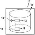
图1示出了本发明的分析方法的第一实施方案,其中使用了具有一个隔室的一个分析区域,并且在所述隔室中固定一种分析物。Figure 1 shows a first embodiment of the analytical method of the present invention, in which one analytical region with one compartment is used and one analyte is immobilized in said compartment.
图2示出了本发明的分析方法的第二实施方案,其中使用了具有一个隔室的一个分析区域,并且在所述隔室中固定多种分析物。Figure 2 shows a second embodiment of the analytical method of the present invention in which one analytical region with one compartment is used and in which a plurality of analytes are immobilized.
图3示出了本发明的分析方法的第三和第四实施方案,其中使用了具有多个隔室的一个分析区域,并且每个隔室固定不同的分析物。Figure 3 shows third and fourth embodiments of the analytical method of the present invention, in which an analytical zone having a plurality of compartments is used, and each compartment immobilizes a different analyte.
图4示出了本发明的分析方法的第五和第六实施方案,其中使用了具有多个隔室的一个分析区域,并且每个隔室固定多种分析物。Figure 4 shows fifth and sixth embodiments of the analytical method of the present invention, in which an analytical zone having a plurality of compartments is used, and each compartment immobilizes a plurality of analytes.
图5示出了本发明的分析方法的第七实施方案,其中使用了多个分析区域,每个分析区域具有一个隔室,并且每个隔室固定不同的分析物。Figure 5 shows a seventh embodiment of the analytical method of the present invention in which a plurality of analysis zones are used, each analysis zone having one compartment and each compartment immobilizing a different analyte.
图6示出了本发明的分析方法的第八实施方案,其中使用了多个分析区域,每个分析区域具有一个隔室,并且每个隔室固定了多种分析物。Figure 6 shows an eighth embodiment of the analytical method of the present invention in which multiple analysis zones are used, each analysis zone having one compartment and each compartment immobilizing multiple analytes.
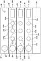
图7示出了本发明的分析方法的第九和第十实施方案,其中使用了多个分析区域,每个分析区域具有多个隔室,并且每个隔室固定不同的分析物。Figure 7 shows ninth and tenth embodiments of the analytical method of the present invention in which multiple analysis areas are used, each analysis area having multiple compartments and each compartment immobilizing a different analyte.
图8示出了本发明的分析方法的第十一和第十二实施方案,其中使用了多个分析区域,每个分析区域具有多个隔室,并且每个隔室固定多种分析物。Figure 8 shows eleventh and twelfth embodiments of the analytical method of the present invention wherein multiple analysis zones are used, each analysis zone having multiple compartments and each compartment immobilizing multiple analytes.
图9A示出了本发明的混合即时检测芯片的结构的相应的顶视图和侧视图,其中顶视图在上部,侧视图在下部。图9B示出构成本发明的混合即时检测芯片的层和零件的结构的分解图。图9C示出了本发明的非线性混合即时检测芯片的实施方案的结构。图9D示出了本发明的混合即时检测芯片阵列的实施方案的结构。FIG. 9A shows the respective top and side views of the structure of the hybrid point-of-care detection chip of the present invention, with the top view at the top and the side view at the bottom. Figure 9B shows an exploded view of the structure of the layers and parts that make up the hybrid point-of-care detection chip of the present invention. Figure 9C shows the structure of an embodiment of the non-linear hybrid point-of-care detection chip of the present invention. Figure 9D shows the structure of an embodiment of the hybrid point-of-care chip array of the present invention.
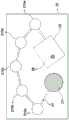
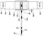
图10A示出了本发明的超顺磁性颗粒成像分析仪的第一实施方案的结构,其中所述分析仪是共线分析仪。图10B是图10A中以虚线示出的中心正方形的放大图,示出了本发明的混合即时检测芯片的结构,所述芯片作为一次性部件位于所述位置以适配到分析仪。FIG. 10A shows the structure of the first embodiment of the superparamagnetic particle imaging analyzer of the present invention, wherein the analyzer is a collinear analyzer. Fig. 10B is an enlarged view of the central square shown in phantom in Fig. 10A, showing the structure of the hybrid point-of-care chip of the present invention as a disposable part in the location to fit into the analyzer.
图11A是示出了本发明的超顺磁性颗粒成像分析仪的第二实施方案的结构的前视图,其中所述分析仪为开放式分析仪。图11B是示出了同一分析仪的结构的侧视图。11A is a front view showing the structure of the second embodiment of the superparamagnetic particle imaging analyzer of the present invention, wherein the analyzer is an open analyzer. FIG. 11B is a side view showing the structure of the same analyzer.
图12A示出了本发明的超顺磁性颗粒成像分析仪的第三实施方案的“E”磁芯激励场的结构。图12B是示出了本发明的混合即时检测芯片的局部放大图,其中所述芯片作为适配到分析仪中的分析仪的一次性部件。Figure 12A shows the structure of the "E" core excitation field of the third embodiment of the superparamagnetic particle imaging analyzer of the present invention. 12B is an enlarged partial view showing a hybrid point-of-care chip of the present invention as a disposable part of the analyzer that fits into the analyzer.
图13A是示出本发明的超顺磁性颗粒成像分析仪的第四实施方案的结构的顶视图,其中所述分析仪是具有两个同心放置的发射线圈和分开的接收线圈的单面分析仪。图13B是示出了本发明的混合即时检测芯片的结构的局部放大图,所述芯片作为分析仪的一次性部件,并与分析仪的发射线圈和接收线圈一起使用。13A is a top view showing the structure of a fourth embodiment of a superparamagnetic particle imaging analyzer of the present invention, wherein the analyzer is a single-sided analyzer with two concentrically placed transmit coils and separate receive coils . 13B is a partial enlarged view showing the structure of the hybrid point-of-care detection chip of the present invention as a disposable part of the analyzer and used with the transmitter and receiver coils of the analyzer.
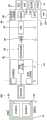
图14是示出本发明的超顺磁性颗粒成像分析仪中的信号链的图。FIG. 14 is a diagram showing the signal chain in the superparamagnetic particle imaging analyzer of the present invention.
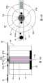
图15A示出了本发明的超顺磁性颗粒成像分析仪的第五实施方案中使用的永磁体的结构的局部侧视图,所述分析仪为霍尔传感器分析仪。图15B是示出了本发明的永磁体和混合即时检测芯片的局部顶视图,其中所述芯片作为分析仪的一次性部件,并与永磁体结合使用。图15C是示出了本发明的分析仪的结构的侧视图。图15D是示出了本发明的分析仪的结构的顶视图。15A shows a partial side view of the structure of the permanent magnet used in the fifth embodiment of the superparamagnetic particle imaging analyzer of the present invention, which is a Hall sensor analyzer. Figure 15B is a partial top view showing a permanent magnet and hybrid point-of-care chip of the present invention as a disposable part of the analyzer and used in conjunction with the permanent magnet. Fig. 15C is a side view showing the structure of the analyzer of the present invention. Fig. 15D is a top view showing the structure of the analyzer of the present invention.
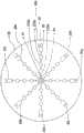
图16示出了与本发明的非线性混合即时检测芯片一起使用的超顺磁性颗粒成像分析仪的第六实施方案的结构。FIG. 16 shows the structure of a sixth embodiment of a superparamagnetic particle imaging analyzer for use with the nonlinear hybrid point-of-care detection chip of the present invention.
图17是示出了基于霍尔传感器的本发明的超顺磁性颗粒成像分析仪中的信号链的图。Figure 17 is a diagram showing the signal chain in the Hall sensor based superparamagnetic particle imaging analyzer of the present invention.
图18示出了实施例1中使用的本发明的混合即时检测芯片。FIG. 18 shows the hybrid point-of-care detection chip of the present invention used in Example 1. FIG.
图19示出了实施例1中的针对第一、第二以及第三分析区域的作为水平轴的SPNP浓度(ng/ml)关于作为垂直轴的磁性响应(Mox)的实验结果。19 shows the experimental results of the SPNP concentration (ng/ml) as the horizontal axis with respect to the magnetic response (Mox) as the vertical axis for the first, second and third analysis regions in Example 1. FIG.
附图中的参考数字如下:10-测定形式上的分析区域(10'或10a'表示连续布置的不同分析区域;11-隔室(11'、11a、11a'、11z表示连续布置的不同隔室);12-分析物;13-用于标记分析物12的超顺磁性纳米颗粒,在本发明中也称为超顺磁性颗粒、超顺磁性纳米颗粒标记或超顺磁性颗粒标记;20-混合即时检测芯片或芯片阵列(20a、20b、20c、20d、20e、20f、20g和20h表示芯片阵列中的各个芯片);210-芯片20中的分析区域(210a、210b、210c、210d和210e表示连续布置的第一、第二、第三、第四以及第五分析区域);21-样品口;22-试剂;23-微通道(23a、23b、23c、23d、23e表示连接芯片的不同部分的不同微通道);24-切换柱;25-切换柱24中的填充材料;26-吸收室;27-吸收垫;28-通风孔;30-SPI分析仪;31-外壳;310-圆筒;311-框架;32-永磁体;33-内部圆筒容积;33a-永磁体的内部圆筒;34-紧固件;35-激励线圈;36-接收线圈;37-无场点或区域(FFP);37a-区域的线性无场点(FFL);37b-无零非磁化区域;38-视场(FOV);39-指示选择场的箭头;40-信号链;41-屏蔽;42-交流驱动场;43-直流驱动场;44-信号前置放大单元;45-低通滤波器;46-模数转换;47-信号放大器;48-条形码阅读器;49-中央处理器(CPU);50-蓝牙;51-无线信号输出(WIFI);52-显示器;53-(无线)打印机;54-图形用户界面(GUI);55-移动应用程序;56-外部12-240V壁式变压器;60-霍尔磁性传感器;60'-霍尔元件;61-空心轴;62-偏置导线和信号输出;63-生成的场线表示(均质磁量子的幻像);64-支撑基座;65-热敏电阻;66-滤波器(用于失调/消除);67-霍尔信号前置放大级。Reference numerals in the figures are as follows: 10 - Analysis areas in the assay format (10' or 10a' represent different analysis areas arranged in succession; 11 - Compartments (11', 11a, 11a', 11z represent different compartments arranged in succession) chamber); 12-analyte; 13-superparamagnetic nanoparticles for labeling analyte 12, also referred to in the present invention as superparamagnetic particles, superparamagnetic nanoparticle labels or superparamagnetic particle labels; 20- Hybrid point-of-care chips or arrays of chips (20a, 20b, 20c, 20d, 20e, 20f, 20g, and 20h represent individual chips in the array of chips); 210 - Analysis areas in chip 20 (210a, 210b, 210c, 210d, and 210e 21-sample port; 22-reagent; 23-microchannel (23a, 23b, 23c, 23d, 23e represent different connection chips) 24-switch column; 25-switch the packing material in column 24; 26-absorption chamber; 27-absorption pad; 28-vent; 30-SPI analyzer; 31-housing; 310-circle 311-frame; 32-permanent magnet; 33-inner cylinder volume; 33a-inner cylinder of permanent magnet; 34-fastener; 35-exciting coil; 36-receiving coil; 37-field-free point or area (FFP); 37a - Linear Field-Free Point (FFL) of the area; 37b - Zero-free non-magnetization area; 38 - Field of View (FOV); 39 - Arrow indicating selection field; 40 - Signal chain; 41 - Shield; - AC drive field; 43 - DC drive field; 44 - signal preamplifier unit; 45 - low pass filter; 46 - analog-to-digital conversion; 47 - signal amplifier; 48 - bar code reader; 49 - central processing unit (CPU ); 50-Bluetooth;51-Wireless Signal Output(WIFI);52-Monitor;53-(Wireless)Printer;54-Graphical User Interface(GUI);55-Mobile Application;56-External 12-240V Wall Transformer ; 60 - Hall magnetic sensor; 60' - Hall element; 61 - Hollow shaft; 62 - Bias wire and signal output; 63 - Field line representation generated (phantom of homogeneous magnetic quantum); 64 - Support base ; 65 - thermistor; 66 - filter (for offset/elimination); 67 - Hall signal preamplifier stage.
具体实施方式Detailed ways
在本发明中,术语“形式”或“测定形式”是指进行分析方法所必需的并且在该分析方法中使用的零件、设备以及试剂的集合。In the present invention, the term "format" or "assay format" refers to the collection of parts, equipment, and reagents necessary to perform an analytical method and used in the analytical method.
本发明的分析方法使用基于朗之万(Langevin)理论的超顺磁性颗粒成像技术,并且检测并分析超顺磁性纳米颗粒(SPNP)——主要是其谐波——对变化的外部磁场的非线性响应。与通过磁性颗粒成像技术测量溶液中的自由磁性颗粒相反,测量固定在固定相上的超顺磁性纳米颗粒标记的分析物的浓度。结果是,本发明的方法仅需要测量分析区域中分析物的总浓度,而无需测量示踪剂的分布。由于分析区域已知,因此无需重建即可测量浓度。The analytical method of the present invention uses superparamagnetic particle imaging technology based on the Langevin theory, and detects and analyzes the non-responsiveness of superparamagnetic nanoparticles (SPNPs), mainly their harmonics, to changing external magnetic fields. Linear response. In contrast to the measurement of free magnetic particles in solution by magnetic particle imaging techniques, the concentration of superparamagnetic nanoparticles-labeled analytes immobilized on a stationary phase is measured. As a result, the method of the present invention requires only the measurement of the total concentration of the analyte in the analysis area and not the distribution of the tracer. Concentrations can be measured without reconstruction since the area of analysis is known.
本发明的方法使用超顺磁性颗粒成像技术,该技术利用超顺磁性纳米颗粒对变化的外部磁场的空间编码的非线性响应来同时定量测定芯片的分析区域中的多种分析物。The methods of the present invention use superparamagnetic particle imaging techniques that exploit the spatially encoded nonlinear response of superparamagnetic nanoparticles to changing external magnetic fields to simultaneously quantify multiple analytes in the analysis region of the chip.
在本发明中,超顺磁性颗粒成像技术用于体外诊断。用于制造超顺磁性纳米颗粒的材料的选择范围要比体内诊断所用的要广泛得多,可以是Co、Fe、CoFe、Co合金、铁氧体、氮化钴、氧化钴、Co-Pd、Co-Pt、铁、铁合金、Fe-Au、Fe-Cr、Fe-N、FeO、Fe-Pd、Fe-Pt、Fe-Zr-Nb-B、Mn-N、Nd-Fe-B、Nd-Fe-B-Nb-Cu、Ni或Ni合金。In the present invention, superparamagnetic particle imaging technology is used for in vitro diagnosis. The choice of materials used to make superparamagnetic nanoparticles is much wider than that used for in vivo diagnostics and can be Co, Fe, CoFe, Co alloys, ferrites, cobalt nitride, cobalt oxide, Co-Pd, Co-Pt, iron, iron alloys, Fe-Au, Fe-Cr, Fe-N, FeO, Fe-Pd, Fe-Pt, Fe-Zr-Nb-B, Mn-N, Nd-Fe-B, Nd- Fe-B-Nb-Cu, Ni or Ni alloys.
在本发明中,具有不同形状的颗粒用于给出不同的谐波。超顺磁性纳米颗粒可以制成不同的几何形状,包括但不限于球形、椭圆形和扁平的。一些颗粒涂覆有不同的涂料,以产生不同的谐波进行分析。In the present invention, particles with different shapes are used to give different harmonics. Superparamagnetic nanoparticles can be fabricated into different geometries, including but not limited to spherical, elliptical, and flat. Some particles are coated with different coatings to generate different harmonics for analysis.
在本发明中,由于不同粒径的颗粒给出不同的谐波,超顺磁性纳米颗粒的尺寸在1和1000nm之间。In the present invention, the size of the superparamagnetic nanoparticles is between 1 and 1000 nm since particles with different particle sizes give different harmonics.
在本发明中,固定颗粒和自由颗粒给出不同的谐波。这就提供了一种从固定的超顺磁性纳米颗粒分离信号的方法。结果是,分析物可以在测定开始运行之后直接测量,而不必洗涤分析区域以去除未结合的超顺磁性纳米颗粒。In the present invention, fixed particles and free particles give different harmonics. This provides a method to separate the signal from the immobilized superparamagnetic nanoparticles. As a result, the analyte can be measured directly after the assay has been run without having to wash the analysis area to remove unbound superparamagnetic nanoparticles.
在本发明中,分析物可以是任何可用超顺磁性纳米颗粒标记并固定在固定相上的物质,包括但不限于有机分子、生物分子、肽、聚合物、氨基酸、蛋白质、酶、抗体、DNA、RNA、病毒、细菌、细胞、无机分子以及药物。In the present invention, the analyte can be any substance that can be labeled with superparamagnetic nanoparticles and immobilized on the stationary phase, including but not limited to organic molecules, biomolecules, peptides, polymers, amino acids, proteins, enzymes, antibodies, DNA , RNA, viruses, bacteria, cells, inorganic molecules and drugs.
在本发明中,可以测量的样品包括但不限于任何体液,诸如全血、血清、血浆、尿液、唾液、粪便、眼泪、汗液。也可以是液体、固体和气体提取物。In the present invention, samples that can be measured include, but are not limited to, any body fluid, such as whole blood, serum, plasma, urine, saliva, feces, tears, sweat. Liquid, solid and gaseous extracts are also possible.
本发明的分析方法在以下实施方案中结合附图进行了进一步说明。在如图1所示的本发明的分析方法的第一实施方案中,进行分析的测定形式含一个分析区域10,该分析区域由一个隔室11组成,该隔室固定以超顺磁性纳米颗粒13标记的分析物12。The analysis method of the present invention is further described in the following embodiments in conjunction with the accompanying drawings. In a first embodiment of the analytical method of the invention as shown in Figure 1, the assay format to be analysed contains an
当测定形式置于本发明的超顺磁性颗粒成像分析仪设备中时,变化的激励场被施加至分析区域10,并且分析区域10和隔室11中的超顺磁性纳米颗粒13响应并且在分析仪的接收线圈中产生谐波信号。产生的谐波信号与隔室11中的超顺磁性纳米颗粒的浓度成正比:When the assay format is placed in the superparamagnetic particle imaging analyzer device of the present invention, a varying excitation field is applied to the


一旦获得系统函数,便可以通过测量接收线圈中的信号来确定形式中的分析物的浓度。Once the system function is obtained, the concentration of the analyte in the form can be determined by measuring the signal in the receiving coil.
在如图2所示的本发明的分析方法的第二实施方案中,采用了以超顺磁性纳米颗粒对变化的外部磁场的非线性响应在测定形式上定量多种分析物。测定形式含一个分析区域10,该分析区域由一个隔室11组成。在隔室11中固定了总数为Z的分析物(示出了第一种分析物12和第Z种分析物12')。数字Z可以是1至20的整数。每种分析物均以超顺磁性纳米颗粒标记(示出了分别用于标记分析物12和12'的超顺磁性纳米颗粒13和13')。In a second embodiment of the analytical method of the present invention as shown in Figure 2, the nonlinear response of superparamagnetic nanoparticles to a changing external magnetic field is employed to quantify various analytes in an assay format. The assay format contains an
当测定形式置于本发明的超顺磁性颗粒成像分析仪中时,变化的激励场被施加至分析区域10和隔室11,并且隔室11中的所有超顺磁性纳米颗粒均响应并且在分析仪的接收线圈中产生谐波信号。磁性颗粒的浓度与其谐波成正比。在隔室11中测得的n次谐波An的振幅是隔室11中所有颗粒的n次谐波的振幅

颗粒i的n次谐波的振幅


由于颗粒所有谐波的比率与浓度无关(参见Rauwerdink,A,2010),因此可以使用以下等式求解隔室11中每个颗粒的浓度:Since the ratio of all harmonics of a particle is independent of concentration (see Rauwerdink, A, 2010), the concentration of each particle in
Ax=bAx=b
其中in


在等式中,谐波从低阶到高阶使用,因为尽管可以使用任何谐波进行计算,但是谐波的振幅会随着阶次变高而迅速降低。通过测量隔室11中的第3至第(2Z+1)次谐波,使用等式确定全部Z种分析物的浓度。可以同时分析最多1(分析区域)·1(隔室)·Z(SPNP)分析物,在这种情况下,为1(分析区域)·1(隔室)×20(SPNP)=20分析物。In the equation, harmonics are used from lower to higher order because although any harmonic can be used for calculations, the amplitude of a harmonic decreases rapidly with higher order. By measuring the 3rd to (2Z+1)th harmonics in
在如图3所示的本发明的分析方法的第三实施方案中,空间编码的隔室中的超顺磁性纳米颗粒对变化的外部磁场的非线性响应被用于定量测定形式上的多种分析物。测定形式含一个分析区域10,该分析区域由Y个隔室组成(示出了第一隔室11和第Y隔室11')。Y是1至20范围内的整数。每个隔室固定不同的分析物(示出了隔室11中的第一分析物12和隔室11'中的第Y分析物12')。每种分析物均以超顺磁性纳米颗粒标记(示出了隔室11中的分析物12的颗粒标记13和隔室11'中的分析物12'的颗粒标记13')。In a third embodiment of the analytical method of the present invention as shown in Figure 3, the nonlinear response of superparamagnetic nanoparticles in spatially encoded compartments to changing external magnetic fields is used to quantify a variety of modalities Analyte. The assay format contains an
当测定形式置于本发明的超顺磁性颗粒成像分析仪中时,聚焦场线圈产生一个隔室11大小的无场空间(FFS)。由于分析区域10的结构(包括隔室的数量、形状以及位置)已知,因此可以基于隔室的位置移动FFS,并将其一次施加至一个隔室。当FFS被施加至隔室11时,由驱动场线圈产生的变化的激励场被施加至隔室。无场隔室11中的超顺磁性纳米颗粒13响应并且在分析仪的接收线圈中产生谐波信号。以在第一实施方案中描述的方式分析固定在隔室11中的分析物12。在分析了隔室11之后,将FFS移至下一隔室并分析固定在下一隔室中的分析物。重复相同的过程,直到对分析区域10中的全部Y个隔室进行过分析为止。如此一来,全部Y种分析物(仅示出了第一种分析物12和第Y种分析物12')均被定量。可以同时分析最多1(分析区域)·Y(隔室)·1(SPNP)分析物,在这种情况下,为1(分析区域)·20(隔室)·1(SPNP)=20分析物。When the assay format is placed in the superparamagnetic particle imaging analyzer of the present invention, the focusing field coil produces a field-free space (FFS) the size of one
在本发明的分析方法的第四实施方案中,SPNP对变化的外部磁场的空间编码的非线性响应被用于在测定形式上同时定量多种分析物。测定形式与图3所示的第三实施方案相同,但是配置使用了不同的分析方法。In a fourth embodiment of the analytical method of the present invention, the spatially encoded non-linear response of SPNPs to changing external magnetic fields is used to quantify multiple analytes simultaneously in an assay format. The assay format is the same as the third embodiment shown in Figure 3, but the configuration uses a different analytical method.
当测定形式置于本发明的超顺磁性颗粒成像分析仪中时,聚焦场线圈产生无场点(FFP)。由于分析区域10的结构(包含隔室(11、11'……)的数量、形状以及位置)已知,因此FFP在分析区域10内以预定路径移动。当变化的激励场施加至FFP上,它会引起FFP内部的SPNP 13、13'……的磁化。由于FFP是空间和时间编码的,因此从FFP产生的信号也是空间和时间编码的。感应的磁化长度与磁性颗粒13、13'……的浓度成正比。磁性颗粒的浓度(Ck(r′))与在该位置(r′)和时间点处的信号


CY是第Y隔室11'中的磁性颗粒的总浓度。
在如图4所示的本发明的分析方法的第五实施方案中,空间编码的隔室中的超顺磁性纳米颗粒对变化的外部磁场的非线性响应被用于在测定形式上定量多种分析物。测定形式含一个分析区域10,该分析区域由Y个隔室组成(示出了第一隔室11和第Y隔室11')。Y是1至20范围内的整数。每个隔室固定Z种分析物(示出了第一分析物12和第Z分析物12')。Z是2至20范围内的整数。Z种分析物分别以Z种超顺磁性纳米颗粒标记(示出了第一SPNP标记13和第Z SPNP标记13')。In a fifth embodiment of the analytical method of the present invention as shown in Figure 4, the nonlinear response of superparamagnetic nanoparticles in spatially encoded compartments to a changing external magnetic field is used to quantify a variety of assay formats Analyte. The assay format contains an
当测定形式置于本发明的超顺磁性颗粒成像分析仪中时,聚焦场线圈产生一个隔室大小的无场空间(FFS)。由于分析区域10的结构(包括隔室11、11'……的数量Y、形状以及位置)已知,因此可以基于隔室的位置移动FFS,并将其一次施加至一个隔室。当FFS被施加至第一隔室11时,由驱动场线圈产生的变化的激励场被施加至隔室。无场隔室11中的SPNP响应并且在接收线圈中产生谐波信号。When the assay format is placed in the superparamagnetic particle imaging analyzer of the present invention, the focused field coil produces a field-free space (FFS) the size of one compartment. Since the structure of the analysis region 10 (including the number Y, shape and location of the
以在第二实施方案中描述的方式分析固定在隔室11中的分析物。对第一隔室11中的分析物12、12'……(分析物的总数量为Z)进行定量。在分析了第一隔室11之后,将FFS移动至第二隔室并分析该隔室,依此类推,直到对分析区域10中的第Y隔室11'进行过分析为止。每个隔室的分析方式均与隔室11相同。可以同时分析最多1(分析区域)·Y(隔室)·Z(SPNP)分析物,在这种情况下,为1(分析区域)·20(隔室)·20(SPNP)=400分析物。The analyte immobilized in the
在本发明的分析方法的第六实施方案中,SPNP对变化的外部磁场的空间编码的非线性响应被用于在测定形式上同时定量多种分析物。本实施方案是分析图4所示的测定形式的另一种方法。In a sixth embodiment of the analytical method of the present invention, the spatially encoded nonlinear response of SPNPs to changing external magnetic fields is used to quantify multiple analytes simultaneously in an assay format. This embodiment is another method of analyzing the assay format shown in FIG. 4 .
当测定形式置于本发明的超顺磁性颗粒成像分析仪中时,聚焦场线圈产生无场点(FFP)。由于分析区域10的结构(包括隔室的数量、形状以及位置)已知,因此FFP在分析区域内以预定路径移动。当变化的激励场施加至FFP时,它会引起FFP内部SPNP的磁化。由于FFP是空间和时间编码的,因此从FFP产生的信号也是空间和时间编码的。来自同一隔室的信号一起处理。When the assay format is placed in the superparamagnetic particle imaging analyzer of the present invention, the focused field coil produces a field-free point (FFP). Since the structure of the analysis area 10 (including the number, shape and location of the compartments) is known, the FFP moves in a predetermined path within the analysis area. When a varying excitation field is applied to the FFP, it induces magnetization of the SPNPs inside the FFP. Since FFPs are spatially and temporally coded, the signals produced from FFPs are also spatially and temporally coded. Signals from the same compartment are processed together.
在隔室中测得的n次谐波的振幅An是该隔室中所有颗粒的n次谐波的振幅

通过使用在实验中测得的第n个振幅(An)和第二实施方案中描述的方法,确定每个颗粒i的振幅


在理想的情况下,磁性颗粒i的浓度或分析物i的浓度(Ci)与FFP处产生的颗粒i的总浓度


在图5所示的本发明的分析方法的第七实施方案中,SPNP对变化的外部磁场的非线性响应被用于在测定形式上同时定量多种分析物。测定形式含X个分析区域(示出了第一分析区域10和第X分析区域10'),并且X是1至20范围的整数。每个分析区域由一个隔室组成(示出了第一分析区域10中的第一隔室11和第X分析区域10'中的第X隔室11')。每个隔室固定以SPNP(示出了第一隔室11中的第一SPNP13和第X隔室11'中的第X SPNP 13')标记的不同分析物(示出了隔室11中的第一分析物12和第X隔室11'中的第X分析物12')。分析方法的第七实施方案与第一实施方案相同,不同之处在于其重复了X次。可以同时分析最多X(分析区域)·1(隔室)·1(SPNP)分析物,在这种情况下,为20(分析区域)·1(隔室)×1(SPNP)=20分析物。In a seventh embodiment of the analytical method of the present invention shown in Figure 5, the nonlinear response of SPNPs to a changing external magnetic field is used to simultaneously quantify multiple analytes in an assay format. The assay format contains X analysis regions (a
在如图6所示的本发明的分析方法的第八实施方案中,SPNP对变化的外部磁场的非线性响应被用于在测定形式上同时定量多种分析物。测定形式由X个分析区域组成(示出了第一分析区域10和第X分析区域10'),并且X是1至20范围内的整数。每个分析区域由一个隔室组成(示出了第一分析区域10中的隔室11和第X分析区域10'中的隔室11')。每个隔室固定Z种分析物(示出了隔室11和11'中的第一分析物12和第Z分析物12'两者),并且Z是1至20范围内的整数。一个隔室中的每种分析物均用不同的SPNP(示出了分别用于第一分析物的第一标记SPNP 13和用于第Z分析物的第Z标记SPNP 13')标记。In an eighth embodiment of the analytical method of the present invention as shown in Figure 6, the nonlinear response of SPNPs to a changing external magnetic field is used to quantify multiple analytes simultaneously in an assay format. The assay format consists of X analysis regions (a
第八实施方案中使用的分析方法与第二实施方案相同,不同之处在于其重复了X次。可以同时分析最多X(分析区域)·1(隔室)·1(SPNP)分析物,在这种情况下,为20(分析区域)·1(隔室)×1(SPNP)=20分析物。The analytical method used in the eighth embodiment is the same as the second embodiment, except that it is repeated X times. Up to X (analysis area) 1 (compartment) 1 (SPNP) analytes can be analyzed simultaneously, in this case 20 (analysis area) 1 (compartment) x 1 (SPNP) = 20 analytes .
在如图7所示的本发明的分析方法的第九实施方案中,空间编码的隔室中SPNP对变化的外部磁场的非线性响应被用于在测定形式上定量多种分析物。测定形式含X个分析区域(示出了第一分析区域10和第X分析区域10'),并且X是1至20范围内的整数。每个分析区域由Y个隔室组成(示出了第一分析区域10中的第一隔室11和第Y隔室11'以及第X分析区域10'中的第一隔室11a和第Y隔室11a'),并且Y是1至20范围内的整数。每个隔室固定以SPNP(示出了用于分析区域10的第一隔室11中的分析物12的SPNP标记13、用于分析区域10的第Y隔室11'中的分析物12'的SPNP标记13'、用于第一分析区域10'的第一隔室11a中的分析物12a的SPNP标记13a以及用于第X分析区域10'的第Y隔室11a'中的分析物12a'的SPNP标记13a')标记的不同分析物(示出了分析区域10的第一隔室11中的第一分析物12和第Y隔室11'中的第Y分析物12',以及分析区域10'的第一隔室11a中的第一分析物12a和第Y隔室11a'中的第Y分析物12a')。In a ninth embodiment of the analytical method of the present invention as shown in Figure 7, the nonlinear response of SPNPs in a spatially encoded compartment to a changing external magnetic field is used to quantify multiple analytes in an assay format. The assay format contains X analysis regions (a
第九实施方案中使用的分析方法与第三实施方案相同,不同之处在于其重复了X次。可以同时分析最多X(分析区域)·Y(隔室)·1(SPNP)分析物,在这种情况下,为20(分析区域)·20(隔室)·1(SPNP)=400分析物。The analytical method used in the ninth embodiment is the same as the third embodiment, except that it is repeated X times. Simultaneous analysis of up to X (analysis area) Y (compartment) 1 (SPNP) analytes, in this case 20 (analysis area) 20 (compartment) 1 (SPNP) = 400 analytes .
在本发明的第十实施方案中,SPNP对变化的外部磁场的空间编码的非线性响应被用于在测定形式上同时定量多种分析物。测定形式与如图7所示的第九实施方案相同,但是本实施方案是分析配置的不同方法。In a tenth embodiment of the present invention, the spatially encoded nonlinear response of SPNPs to changing external magnetic fields is used to quantify multiple analytes simultaneously in an assay format. The assay format is the same as the ninth embodiment shown in Figure 7, but this embodiment is a different method of analysis configuration.
第十实施方案中使用的分析方法与第四实施方案相同,不同之处在于其重复了X次。可以同时分析最多X(分析区域)·Y(隔室)·1(SPNP)分析物,在这种情况下,为20(分析区域)·20(隔室)×1(SPNP)=400分析物。The analytical method used in the tenth embodiment is the same as the fourth embodiment, except that it is repeated X times. Simultaneous analysis of up to X (analysis area) Y (compartment) 1 (SPNP) analytes, in this case 20 (analysis area) 20 (compartment) x 1 (SPNP) = 400 analytes .
在如图8所示的本发明的分析方法的第十一实施方案中,空间编码的隔室中SPNP对变化的外部磁场的非线性响应被用于在测定形式上定量多种分析物。测定形式含X个分析区域(示出了第一分析区域10和第X分析区域10'),并且X是1至20范围内的整数。每个分析区域由Y个隔室组成(示出了第一分析区域10中的第一隔室11和第Y隔室11'以及第Y分析区域10'中的第一隔室11a和第Y隔室11a'),并且Y是1至20范围内的整数。每个隔室可以固定Z种分析物(示出了第一分析区域10中隔室11中的第一分析物12和第Z分析物12z以及隔室11'中的第一分析物12'和第Z分析物12z';和第X分析区域10'中隔室11a中的第一分析物12a和第Z分析物12b以及隔室11a'中的第一分析物12a'和第Z分析物12b'),Z可以是1至20范围内的整数。每个分析物分别以不同的SPNP标记(示出了分别用于分析区域10的隔室11中的分析物12和12z的SPNP 13和13z以及隔室11'中的分析物12'和12z'的SPNP 13'和13z';和分别用于分析区域10'的隔室11a中的分析物12a和12b的SPNP13a和13b以及隔室11a'中的分析物12a'和12b'的SPNA 13a'和13b')。In an eleventh embodiment of the analytical method of the present invention as shown in Figure 8, the nonlinear response of SPNPs in a spatially encoded compartment to a changing external magnetic field is used to quantify multiple analytes in an assay format. The assay format contains X analysis regions (a
第十一实施方案中使用的分析方法与第三实施方案相同,不同之处在于其重复了X次。可以同时分析最多X(分析区域)·Y(隔室)·Z(SPNP)分析物,在这种情况下,为20(分析区域)·20(隔室)·20(SPNP)=8,000分析物。The analytical method used in the eleventh embodiment is the same as the third embodiment, except that it is repeated X times. Simultaneous analysis of up to X (analysis area) Y (compartment) Z (SPNP) analytes, in this case 20 (analysis area) 20 (compartment) 20 (SPNP) = 8,000 analytes .
在本发明的分析方法的第十二实施方案中,SPNP对变化的外部磁场的空间编码的非线性响应被用于在测定形式上同时定量多种分析物。测定形式与图8所示的第十一实施方案相同,本实施方案是分析配置的不同方法。本实施方案中使用的分析方法与第六实施方案相同,不同之处在于其重复了X次。可以同时分析最多X(分析区域)·Y(隔室)·X(SPNP)分析物,在这种情况下,为20(分析区域)·20(隔室)·20(SPNP)=8,000分析物。In a twelfth embodiment of the analytical method of the present invention, the spatially encoded nonlinear response of SPNPs to changing external magnetic fields is used to quantify multiple analytes simultaneously in an assay format. The assay format is the same as the eleventh embodiment shown in Figure 8, this embodiment is a different method of analyzing the configuration. The analytical method used in this embodiment is the same as the sixth embodiment, except that it is repeated X times. Simultaneous analysis of up to X (analysis area) Y (compartment) X (SPNP) analytes, in this case 20 (analysis area) 20 (compartment) 20 (SPNP) = 8,000 analytes .
如这些实施方案所示,本发明的分析方法使用超顺磁性颗粒成像技术定量测量固定在固定相上的分析物。该分析方法通过测量由磁性标记的磁化引起的磁通量的变化,同时用多路测定测量了固定在3维固定相上的分析样品中多种磁性标记分析物的浓度。As shown in these embodiments, the analytical methods of the present invention use superparamagnetic particle imaging to quantitatively measure analytes immobilized on a stationary phase. This analytical method measures the concentration of multiple magnetically labeled analytes in an analytical sample immobilized on a 3-dimensional stationary phase by measuring the changes in magnetic flux caused by the magnetization of the magnetic labels using a multiplex assay.
在本发明中,超顺磁性颗粒成像技术与本发明的三维混合即时检测芯片合作良好,并且还可以用于其他测定形式,诸如侧流测试、微流体测定、“芯片实验室”设备以及独立的生物传感器。对于用于化学和生物试剂的高通量且成本效益良好的检测平台的需求尚未得到满足。这些平台可用于大量分析和诊断应用,包括筛选用于药物开发、毒性研究、即时检测诊断和环境监测的化学库。常规传感器通常使用化学、光学、光谱、基于电阻抗或质量的检测来解释生化现象。超顺磁性颗粒成像使用不同大小、形状和成分的磁性标记或磁性纳米颗粒。In the present invention, superparamagnetic particle imaging technology works well with the three-dimensional hybrid point-of-care detection chip of the present invention, and can also be used in other assay formats, such as lateral flow assays, microfluidic assays, "lab-on-a-chip" devices, and stand-alone biological sensor. There is an unmet need for high-throughput and cost-effective detection platforms for chemical and biological reagents. These platforms can be used for a wide variety of analytical and diagnostic applications, including screening chemical libraries for drug development, toxicity studies, point-of-care diagnostics, and environmental monitoring. Conventional sensors typically use chemical, optical, spectroscopic, electrical impedance- or mass-based detections to explain biochemical phenomena. Superparamagnetic particle imaging uses magnetic labels or magnetic nanoparticles of various sizes, shapes, and compositions.
使用超顺磁性颗粒成像技术的本发明的分析方法代表了一种执行许多医学诊断测定和伴随药物监测测试的直接和准确检测的新范例。超顺磁性颗粒成像技术不仅扩展了基于磁性的诊断测定的有效性和灵敏度,还克服了其他基于磁性的测定的主要缺点,即在单次测量中同时检测多种分析物,具有基于光学的测定的优势。本发明使得开发许多需要快速、灵敏装置却无需高昂的现代分析实验室相关费用的分析方法成为可能。现在,诸如DNA/RNA分析、环境测试、化学和生物战检测、滥用药物筛查、食品供应质量检测等测试可以通过利用超顺磁性颗粒成像技术和生产具有可生物降解的一次性测定芯片的小型便携式手持装置来进行改进。The analytical method of the present invention using superparamagnetic particle imaging technology represents a new paradigm for performing direct and accurate detection of many medical diagnostic assays and accompanying drug monitoring tests. Superparamagnetic particle imaging technology not only expands the effectiveness and sensitivity of magnetic-based diagnostic assays, but also overcomes the major drawback of other magnetic-based assays, the simultaneous detection of multiple analytes in a single measurement, with optical-based assays The advantages. The present invention makes it possible to develop many analytical methods that require fast, sensitive devices without the high costs associated with modern analytical laboratories. Tests such as DNA/RNA analysis, environmental testing, chemical and biological warfare testing, drug of abuse screening, food supply quality testing, and more can now be achieved by utilizing superparamagnetic particle imaging technology and producing small-scale biodegradable single-use assay chips Portable handheld device for improvement.
本发明还提供了一种可以与本发明的基于超顺磁性纳米颗粒的分析方法结合使用的混合即时检测芯片。The present invention also provides a hybrid instant detection chip that can be used in combination with the superparamagnetic nanoparticle-based analysis method of the present invention.
本发明的混合即时检测芯片包含:样品引入区域,样品被引入其中;切换柱,样品流在其中被引导至芯片的不同层级;分析区域,分析物在其中被捕获、富集并清洁;废物室,在其中收集多余样品和洗涤液;以及微通道,芯片上的不同元素通过其互相连通。在这一设计中,液体样品可以通过毛细力自动从样品引入区域流至吸收室。它还可包括样品分散通道、试剂存储槽以及混合端口和泵。The hybrid point-of-care chip of the present invention comprises: a sample introduction area into which the sample is introduced; a switching column in which the sample flow is directed to different levels of the chip; an analysis area in which the analytes are captured, enriched and cleaned; a waste chamber , where excess sample and washing fluid are collected; and microchannels, through which different elements on the chip communicate with each other. In this design, the liquid sample can flow automatically from the sample introduction area to the absorption chamber by capillary force. It can also include sample dispersion channels, reagent storage tanks, and mixing ports and pumps.
本发明的混合即时检测芯片的分析区域容纳3维多隔室固定相,分析物捕获材料装载于其中。样品流体以三维路径流向并通过本身即为3维区域的分析区域的固定相。它们的大小和位置已知,因此无需重建即可测量分析物的浓度。The analysis area of the hybrid point-of-care detection chip of the present invention accommodates a 3-dimensional multi-compartment stationary phase in which the analyte capture material is loaded. The sample fluid flows in a three-dimensional path through the stationary phase of the analysis region, which is itself a three-dimensional region. Their size and location are known, so analyte concentrations can be measured without reconstruction.
本发明的混合即时检测形式由液体样品的流动路径中的固定相构成。固定相可以直接分配到孔中,通过生物学方法生长,也可以由自组装塑料和聚合物、二氧化硅或等同物制成的材料的预成型品组成,诸如为有机/非有机结构。示例为自然界中生物制成的叠层石、温泉中无机形成的玛瑙或蛋白石凝胶等胶体矿物,竹笋或香蕉树茎叶中的蜂窝状壁和隔室。所有天然结构由DNA/RNA生物学活性蓝图控制,均可用于本发明。The hybrid point-of-care format of the present invention consists of a stationary phase in the flow path of the liquid sample. Stationary phases can be dispensed directly into wells, grown by biological methods, or can be composed of preforms of self-assembling plastics and materials made of polymers, silica or equivalent, such as organic/non-organic structures. Examples are bio-made stromatolites in nature, colloidal minerals such as agate or opal gels formed inorganically in hot springs, honeycomb-like walls and compartments in bamboo shoots or banana tree stems and leaves. All native structures are governed by a blueprint of DNA/RNA biological activity and can be used in the present invention.
这些结构被置于优选的层压结构内形成的空隙中,尽管块状或浇铸结构也可以用来制造本发明中的结构。在本发明中被称为柱、捕获区或分析区,他们允许液体样品渗透穿过功能性的“固定相”,该功能性“固定相”实际上是具有极大表面积的多孔材料。用夹心或竞争性免疫测定或本领域众所周知的DNA/RNA生物芯片的类似化学方法对分析区域进行功能化。通过使用如免疫测定法中的抗体或抗原或用磁性纳米颗粒标记的小型DNA探头,在这些区域中捕获感兴趣的分析物。或者如在竞争性测定中,分析物竞争功能化固定相表面结构上的结合位点。所有引入的样品均流过从亲水性/疏水性薄膜叠层结合形成的3维通道流经直线区域或圆柱的每个垂直路径。These structures are placed in voids formed within the preferred laminate structure, although block or cast structures can also be used to make the structures of the present invention. Referred to in the present invention as the column, capture zone or analysis zone, they allow the liquid sample to permeate through a functional "stationary phase" which is actually a porous material with an extremely large surface area. The assay regions are functionalized using sandwich or competitive immunoassays or similar chemistry of DNA/RNA biochips well known in the art. Analytes of interest are captured in these regions by using, for example, antibodies or antigens in immunoassays or small DNA probes labeled with magnetic nanoparticles. Alternatively, as in a competitive assay, the analyte competes for binding sites on the surface structure of the functionalized stationary phase. All incoming samples flow through each vertical path from the 3-dimensional channel formed by the combination of the hydrophilic/hydrophobic film stack through a linear region or cylinder.
在优选的形式中,柱空隙由多叠片薄膜形成,该薄膜可以是纸、聚合物、塑料或金属化塑料或金属材质。这些薄膜可购自Adhesive Research、3M、DuPont Polymers、Pall、Coveme和Tesa。薄膜具有不同的表面涂层和性质,例如一些是亲水的或疏水的。它们的厚度可以在.001″和.020″之间,优选在.002″和.015″之间,最优选在.002″和.009″之间。根据磁性读取系统的要求,所有这些叠片都可以转换为所需的形式。版本为具有分散样品引入装置、捕获或分析区域和最终存储芯的多路复用线性形式、更快速的圆柱形式以及部分盘(partial disk)。In a preferred form, the column voids are formed from a multi-laminate film, which may be paper, polymer, plastic or metallized plastic or metal. These films are available from Adhesive Research, 3M, DuPont Polymers, Pall, Coveme and Tesa. Films have different surface coatings and properties, for example some are hydrophilic or hydrophobic. Their thickness may be between .001" and .020", preferably between .002" and .015", most preferably between .002" and .009". All these laminations can be converted into the desired form according to the requirements of the magnetic reading system. Versions are multiplexed linear format with discrete sample introduction device, capture or analysis area and final memory core, faster cylindrical format and partial disk.
每个柱彼此之间液体连通,液体从柱的底部流到顶部,然后从相邻柱的顶部流到底部,并且从下一个相邻柱的底部流到顶部,最终流到芯构件(取决于分析区域的数量)。每一个或全部的通道和柱都可能截留夹带的空气并形成气穴,从而阻塞液体的流动。如果截留的空气成为问题,则可以通过在每个柱的顶部设置小的通风孔来解决。这一通风孔允许截留的空气逸出流体通道和柱,从而防止液体阻塞,但该通风孔足够小,不会允许液体溢出。这些通风孔中可以放置多孔塑料,与液体接触时闭合或者被制造得足够小以使得液体样品的表面张力可防止液体溢出,这在本领域中已知。这一尺寸可以在0.1至10微米的范围内,并且优选地在5微米左右。其他方法是可以通过确保毛细作用力足够使夹带的空气在流体流动之前移动来防止这一情况的发生,而这是通过选择通道中的材料或涂层来实现的。Each column is in liquid communication with each other, with liquid flowing from the bottom to the top of the column, then from the top to the bottom of the adjacent column, and from the bottom to the top of the next adjacent column, and finally to the core member (depending on the number of analysis areas). Each or all of the channels and columns may trap entrained air and create air pockets, thereby blocking the flow of liquid. If trapped air is a problem, it can be solved by placing small vents in the top of each column. This vent allows trapped air to escape the fluid channel and column, preventing liquid blockage, but is small enough not to allow liquid to escape. These vent holes can be placed in porous plastic, closed when in contact with the liquid or made small enough that the surface tension of the liquid sample prevents the liquid from spilling, as is known in the art. This dimension may be in the range of 0.1 to 10 microns, and is preferably around 5 microns. Other methods can prevent this from happening by ensuring that the capillary force is sufficient to move the entrained air before the fluid flows, which is achieved by the choice of material or coating in the channel.
在样品引入区域和控制所需分析区域的流向、速度和3维层级的连通通道之间,是将流向流体通道的液体样品流切换至所需的第一分析柱的较小的柱。本发明中的“切换柱”可以具有或不具有过滤器、封闭剂或结合物(结合物是磁性标记的识别元素,例如在夹心测定中,可以在分析柱中捕获并进行测量的抗体或蛋白质)。这些板载试剂使得不再需要在施加至样品引入区域之前将样品与结合物预混合。因此,增加了保质期和灵敏度并降低了测定的变动系数。Between the sample introduction region and the communication channels that control the flow direction, velocity and 3-dimensional hierarchy of the desired analysis region are smaller columns that switch the flow of liquid sample to the fluid channel to the desired first analysis column. A "switching column" in the present invention may or may not have a filter, a blocking agent, or a binding agent (the binding agent is a magnetically labeled recognition element, such as in a sandwich assay, an antibody or protein that can be captured in the analytical column and measured ). These on-board reagents eliminate the need to premix the sample with the conjugate prior to application to the sample introduction area. Therefore, shelf life and sensitivity are increased and the coefficient of variation of the assay is reduced.
本发明中的样品引入装置可以含分离红细胞的装置。该装置防止柱的阻塞,因为红细胞改变其形状的能力和/或释放内部流体的能力在溶血过程中可能会造成对分析区域的捕获化学物质的干扰。The sample introduction device of the present invention may contain a device for separating red blood cells. The device prevents clogging of the column, as the ability of the red blood cells to change their shape and/or release the internal fluid during hemolysis may cause interference with capture chemicals in the analysis area.
每个柱彼此液体连通,不论是在同一平面上,还是通过将样品流划分至不同的区域来有目的地分离分析区域以避免化学干扰或使所得测量的分析更精确。示例是,当测量样品中的分析物与来自同一样品的小浓度分析物相比具有相对较高浓度时。所得的测量结果往往会模糊小浓度分析物的读数。通过将样品流变为不同的3维层级样品流,可以最小化这2种分析物的任何干扰。Each column is in liquid communication with each other, either on the same plane or by dividing the sample flow into different regions to purposely separate the analysis regions to avoid chemical interferences or to make the analysis of the resulting measurements more precise. An example is when the analyte in the measurement sample has a relatively high concentration compared to a small concentration of analyte from the same sample. The resulting measurements tend to obscure readings for small concentrations of analytes. By changing the sample flow into a different 3-dimensional hierarchical sample flow, any interference from the 2 analytes can be minimized.
本发明的混合即时检测芯片是具有固定相分析区域的3维多层级构造。其通过将薄膜的层进行层压在一起制成。在层压之前,将混合即时检测芯片的某些特性结合到薄膜中。层压后创建其他特性。样品在其中流动的层称为层级。每个芯片可以具有1至20个层级,优选地1至10个层级The hybrid instant detection chip of the present invention is a 3-dimensional multi-level structure with a stationary phase analysis area. It is made by laminating layers of film together. Certain properties of the hybrid point-of-care chip are incorporated into the film prior to lamination. Additional features are created after lamination. The layers in which the sample flows are called layers. Each chip may have 1 to 20 levels, preferably 1 to 10 levels
混合即时检测芯片由1至5个样品引入区域、1至5个切换柱、0至10个试剂槽、1至20个分析区域以及1至5个液体吸收部位组成。样品引入区域、试剂槽、分析区域以及流体吸收部位通过微流体通道和通孔(垂直互连通道)连接,从而可将样品划分并导向不同的层级。混合即时检测芯片可以带有或不带有连接至样品引入区的液体驱动机构,诸如隔膜泵。The hybrid point-of-care detection chip consists of 1 to 5 sample introduction areas, 1 to 5 switching columns, 0 to 10 reagent tanks, 1 to 20 analysis areas, and 1 to 5 liquid absorption sites. The sample introduction area, reagent tank, analysis area, and fluid absorption site are connected by microfluidic channels and through-holes (vertically interconnected channels), so that samples can be divided and directed to different levels. The hybrid point-of-care chip may or may not have a liquid drive mechanism, such as a diaphragm pump, connected to the sample introduction area.
用于混合即时检测芯片的薄膜由塑料、粘合剂、纸、木材、纤维、硅、聚二甲基硅氧烷(PDMS)、聚甲基丙烯酸甲酯(PMMA)、玻璃纤维、纤维素、多糖、蛋白质聚合物、压延颗粒制成。可以对薄膜表面进行改性以具有所需特性,包含疏水性和亲水性Films for hybrid point-of-care chips are made of plastic, adhesive, paper, wood, fiber, silicon, polydimethylsiloxane (PDMS), polymethylmethacrylate (PMMA), fiberglass, cellulose, It is made of polysaccharides, protein polymers, and calendered granules. Film surfaces can be modified to have desired properties, including hydrophobicity and hydrophilicity
每个样品引入区可以具有或不具有红细胞分离装置。其还可含识别和固定样品中感兴趣的分析物所需的试剂。样品引入区可容纳1至200微升样品。Each sample introduction zone may or may not have a red blood cell separation device. It may also contain the reagents required to identify and immobilize the analyte of interest in the sample. The sample introduction area can hold from 1 to 200 microliters of sample.
样品可以是全血、血浆、血清、尿液、唾液、眼泪、汗液、粪便提取物、DNA/RNA提取物、含抗原的溶液、抗体、酶、蛋白质、肽、氨基酸、激素、有机和无机分子、生物标志物、工业污染物、病原体、病毒、细胞、细胞培养物提取物以及环境样品。Samples can be whole blood, plasma, serum, urine, saliva, tears, sweat, fecal extracts, DNA/RNA extracts, solutions containing antigens, antibodies, enzymes, proteins, peptides, amino acids, hormones, organic and inorganic molecules , biomarkers, industrial pollutants, pathogens, viruses, cells, cell culture extracts, and environmental samples.
试剂槽中含识别和固定感兴趣的分析物所需的试剂包括磁性、荧光、化学发光和放射性颗粒;以抗体、蛋白质、DNA/RNA探头或螯合剂功能化的磁性、荧光、化学发光和放射性颗粒;荧光、化学发光或放射性标记的抗体、蛋白质、DNA/RNA探头和螯合剂。试剂槽可以在相同的或不同的样品路径中。可以将试剂直接置于试剂槽中或吸收到固体支持物上。Reagent wells containing reagents required to identify and immobilize analytes of interest include magnetic, fluorescent, chemiluminescent, and radioactive particles; magnetic, fluorescent, chemiluminescent, and radioactive functionalized with antibodies, proteins, DNA/RNA probes, or chelators Particles; fluorescent, chemiluminescent or radiolabeled antibodies, proteins, DNA/RNA probes and chelators. Reagent wells can be in the same or different sample paths. The reagents can be placed directly in the reagent well or absorbed onto a solid support.
每个分析区域由固定相的1至20个部分组装而成。分析区域的不同部分可以由相同或不同的固定相组成。固定相可以是颗粒,该颗粒由塑料、二氧化硅、玻璃、氧化铝、有机聚合物、无机聚合物和可生物降解的聚合物制成;或孔膜,该孔膜由塑料、纤维、聚合物、多糖、纤维素、纸、木材、生物构造、生物支架、玻璃纤维、可生物降解的聚合物和蛋白质聚合物构造;非水溶性凝胶;胶体。膜可以是织造的、非织造的或压延颗粒。固定相通过物理吸附或与对感兴趣的分析物具有特异性的识别试剂共价键合而功能化。固定相可以预成型为分析区域的形状和大小后置于区域中,或者直接分配到区域中。分析区域可以构造在一个层级内或跨多个层级。Each analysis zone is assembled from 1 to 20 parts of the stationary phase. Different parts of the analysis area may consist of the same or different stationary phases. The stationary phase can be particles made of plastics, silica, glass, alumina, organic polymers, inorganic polymers and biodegradable polymers; or porous membranes made of plastics, fibers, polymeric polymers, polysaccharides, cellulose, paper, wood, bioconstructs, bioscaffolds, glass fibers, biodegradable polymers and protein polymer constructs; water-insoluble gels; colloids. Films can be woven, nonwoven or calendered particles. The stationary phase is functionalized by physical adsorption or covalent bonding with a recognition reagent specific for the analyte of interest. The stationary phase can be preformed into the shape and size of the analysis area and placed in the area, or dispensed directly into the area. Analysis areas can be structured within a hierarchy or across multiple hierarchies.
每个吸收部位均由具有流体吸收垫的腔室组成。垫由以下制成:孔膜,该孔膜由塑料、纤维、聚合物、多糖、纤维素、纸、木材、生物构造、生物支架、玻璃纤维、可生物降解的聚合物和蛋白质聚合物构造;水凝胶;颗粒,压延颗粒。Each absorbent site consists of a chamber with a fluid-absorbent pad. The pads are made of: a porous membrane constructed of plastic, fibers, polymers, polysaccharides, cellulose, paper, wood, biostructures, bioscaffolds, glass fibers, biodegradable polymers, and protein polymers; Hydrogels; Granules, Calendered Granules.
叠片的材料可以是可生物降解的,并且可以由多种会迅速降解因而不会对环境造成不利影响的聚合物、纤维、赛璐珞和纸制成。示例是没有传统的塑料盒支撑测试结构;支撑整合到层压板测试设计中并且自我支撑的。The laminate material can be biodegradable and can be made from a variety of polymers, fibers, celluloid, and papers that degrade rapidly without adversely affecting the environment. An example is a test structure without the traditional plastic box support; the support is integrated into the laminate test design and is self-supporting.
结合图9A至9D,本发明的混合即时检测芯片的结构在以下实施方案中进一步进行了说明。在如图9A所示的本发明的混合即时检测芯片的一个实施方案中,本发明的三维混合即时检测芯片20包含一个样品引入区域21形式的样品引入区域;三个分析区域210a、210b和210c;切换柱24;以及具有通风孔28的吸收室26形式的流体吸收部位。按照顺序,样品引入区域21和切换柱24通过微通道23a连接。切换柱24和第一分析区域210a通过微通道23b连接。第一分析区域210a和第二分析区域210b通过微通道23c连接。第二分析区域210b和第三分析区域210c通过微通道23d连接。第一分析区域210a是具有第一隔室211a、第二隔室211b以及第三隔室211c的多隔室分析区域。图9A中的箭头示出了样品在芯片中的流动。9A to 9D, the structure of the hybrid point-of-care detection chip of the present invention is further described in the following embodiments. In one embodiment of the hybrid point-of-care test chip of the present invention as shown in FIG. 9A, the three-dimensional hybrid point-of-
芯片上发生的测定的化学和生物反应所需的试剂22被预装载于样品引入区域21中。分析样品的量为1至500微升,通常地1至100微升,优选地5至10微升。样品可以进行预处理或不进行处理,包括但不限于血清、血浆、唾液、汗液、眼泪、痰液、尿液;拭子上的提取的表面擦拭物,乃至半固体,诸如细胞培养物和粪便物、全血(如果在样品引入区域21的结构中合并有红血分离机构,用于全血分析)。The
将样品添加到样品引入区域21中并快速溶解在试剂22中。样品与试剂22混合,通过微通道23a,并进入切换柱24。切换柱24的功能是将样品导向至不同层级。在本实施方案中,切换柱24经由微通道23b将样品引导至芯片20的分析区域210a的上层级(如果需要,它也可以将样品流切换至下层级)。在本发明的多层级设计中,切换柱24可以根据需要将样品切换至任何层级。切换柱24中的填充材料25还用作过滤器,以去除样品中的固体杂质并将清洁的样品输送到分析区域。通过切换柱24后,样品通过微通道23b并进入第一分析区域210a。The sample is added to the
通常,本发明的混合即时检测芯片中的分析区域可以制成具有1至20个隔室,典型地1至10个隔室,并且优选地1至5个隔室。在本实施方案中,有3个隔室211a、211b和211c。Typically, the analysis area in the hybrid point-of-care chip of the present invention can be made to have 1 to 20 compartments, typically 1 to 10 compartments, and preferably 1 to 5 compartments. In this embodiment, there are three
每个隔室可以取决于测定制成具有相同或不同的固定相。固定相可以是颗粒,该颗粒由塑料、二氧化硅、玻璃、氧化铝、有机聚合物、无机聚合物和可生物降解的聚合物制成;或孔膜,该孔膜由塑料、纤维、聚合物、多糖、纤维素、纸、木材、生物构造、生物支架、玻璃纤维、可生物降解的聚合物和蛋白质聚合物构造;非水溶性凝胶;胶体。膜可以是织造的、非织造的或压延颗粒。固定相通过物理吸附或与对感兴趣的分析物具有特异性的识别试剂共价键合而功能化。固定相可以预成型为分析区域的形状和大小后置于区域中,或者直接分配到区域中。分析区域可以构造在一个层级内或跨多个层级。每个隔室可以固定不同的分析物。Each compartment can be made with the same or a different stationary phase depending on the assay. The stationary phase can be particles made of plastics, silica, glass, alumina, organic polymers, inorganic polymers and biodegradable polymers; or porous membranes made of plastics, fibers, polymeric polymers, polysaccharides, cellulose, paper, wood, bioconstructs, bioscaffolds, glass fibers, biodegradable polymers and protein polymer constructs; water-insoluble gels; colloids. Films can be woven, nonwoven or calendered particles. The stationary phase is functionalized by physical adsorption or covalent bonding with a recognition reagent specific for the analyte of interest. The stationary phase can be preformed into the shape and size of the analysis area and placed in the area, or dispensed directly into the area. Analysis areas can be structured within a hierarchy or across multiple hierarchies. Each compartment can hold a different analyte.
当样品通过第一分析区域210a时,感兴趣的分析物被捕获。其余样品离开第一分析区域210a。在该过程中,分析物由具有选择性固定相的隔室分离。该分析物也在隔室中富集,并由通过的样品液体进行清洁。本发明中的多隔室设计使得多路复用成为可能。As the sample passes through the
通过微通道23c后,样品随后进入第二分析区域210b。分析区域210b可以具有与第一分析区域210a相同的构造,包括隔室的数量、固定相的材料以及装载于隔室中的不同捕获材料的数量。通过第二分析区域210b后,第二组分析物被分离并捕获。样品继续移动经过微通道23d并进入第三分析区域210c。第三组分析物在第三分析区域210c中被分离。剩余的样品流体和过量试剂被吸收室26中的流体吸收垫27吸收。吸收垫27由以下制成:孔膜,该孔膜由塑料、纤维、聚合物、多糖、纤维素、纸、木材、生物构造、生物支架、玻璃纤维、可生物降解的聚合物和蛋白质聚合物构造;水凝胶;颗粒或压延颗粒。After passing through the
在本发明中,混合即时检测芯片可以被制成具有1至20个分析区域,通常地1至10个分析区域,并且优选地1至6个分析区域。In the present invention, the hybrid point-of-care detection chip can be made to have 1 to 20 analysis areas, typically 1 to 10 analysis areas, and preferably 1 to 6 analysis areas.
图9B示出了本发明的混合即时检测芯片的构造。本发明的混合即时检测芯片20是具有固相分析区域210a、210b和210c的3维多层级构造。在本实施方案中,芯片20通过将薄膜的层(包括底层201)层压在一起构成。FIG. 9B shows the construction of the hybrid point-of-care detection chip of the present invention. The hybrid point-of-
在本发明中,在层压之前将混合即时检测芯片的一些特征结合到薄膜中。层压后创建其他特征。样品在其中流动的层称为层级。每个芯片可以具有1至20个层级,优选地1至10个层级。In the present invention, some features of the hybrid point-of-care chip are incorporated into the film prior to lamination. Create other features after lamination. The layers in which the sample flows are called layers. Each chip may have 1 to 20 levels, preferably 1 to 10 levels.
在本发明中,混合即时检测芯片由1至5个样品引入区域、0至10个试剂槽、1至20个分析区域以及1至5个流体吸收部位组成。样品引入区域、试剂槽、分析区域以及流体吸收部位通过微流体通道和通孔(垂直互连通道)连接,从而允许将样品划分并导向不同的层级。混合即时检测芯片可以带有或不带有液体驱动机构。In the present invention, the hybrid point-of-care detection chip consists of 1 to 5 sample introduction areas, 0 to 10 reagent tanks, 1 to 20 analysis areas, and 1 to 5 fluid absorption sites. The sample introduction area, reagent tank, analysis area, and fluid absorption site are connected by microfluidic channels and through-holes (vertically interconnected channels), allowing the sample to be divided and directed to different levels. Hybrid point-of-care chips are available with or without a liquid drive mechanism.
用于混合即时检测芯片的薄膜由塑料、粘合剂、纸、木材、纤维、硅、聚二甲基硅氧烷(PDMS)、聚甲基丙烯酸甲酯(PMMA)、玻璃纤维、纤维素、多糖、蛋白质聚合物、压延颗粒制成。可以对薄膜的表面进行改性以具有所需特性,包括疏水性和亲水性。Films for hybrid point-of-care chips are made of plastic, adhesive, paper, wood, fiber, silicon, polydimethylsiloxane (PDMS), polymethylmethacrylate (PMMA), fiberglass, cellulose, It is made of polysaccharides, protein polymers, and calendered granules. The surface of the film can be modified to have desired properties, including hydrophobicity and hydrophilicity.
在如图9B所示的芯片20的构造中,芯片20由5层薄膜组成,即底层201、底层通道层202、中间层203、顶层通道层204以及顶层205。基于设计要求对薄膜的厚度进行调整。微通道由通道层202和204形成。当组装层201、202和203时,形成将样品引入区域21连接至切换柱24的微通道23a、将第一分析区域210a连接至第二分析区域210b的微通道23c,以及将第三分析区域210c连接至吸收室26的微通道23e。在添加层204和205之后,形成将切换柱24连接至第一分析区域210a的微通道23b,和将第二分析区域210b连接至第三分析区域210c的微通道23d。同时,构造了切换柱24和分析区域。该结构允许样品通过微通道在位置之间水平穿行,并通过切换柱和分析区域在层级之间垂直穿行。在添加层204和205以完成芯片的构造之前,需要通过分配颗粒或放置预成型的膜将固定相材料置于切换柱和分析区域中。In the configuration of the
图9B所示的芯片20仅用于说明。可以将附加的功能,诸如更多的分析区域或试剂槽添加到芯片上。层级数量可以通过添加更多的薄膜层来增加。The
图9C描绘了本发明的混合即时检测芯片的另一实施方案,其利用了本发明的混合即时检测芯片中使用微通道在位置之间进行通信的灵活性,因此芯片上的特征不必以线性方式布置,这一点不同于侧流设计。本实施方案中的芯片20的构造与图9A和9B中描述的那些相同,不同之处在于分析区域210a、210b、210c、210d和210e沿着圆弧布置。该布置允许芯片20或检测器以圆周运动移动,从而可以显著降低设计和制造成本。Figure 9C depicts another embodiment of the hybrid point-of-care detection chip of the present invention that takes advantage of the flexibility of using microchannels in the hybrid point-of-care detection chip of the present invention to communicate between locations so that the features on the chip do not have to be in a linear fashion layout, which differs from lateral flow designs. The configuration of the
本发明的混合即时检测芯片的另一实施方案是如图9D所示的芯片阵列的形式,其中芯片20是具有8个个体芯片20a、20b、20c、20d、20e、20f、20g和20h的芯片阵列的形式。这些个体的构造与图9A和9B中描述的那些相同,不同之处在于膜的每一层均具有多组芯片特征,并且在同一盘上的所有芯片在如图9D所示的集中位置中打杂一个样品引入区域21。在本实施方案中,每个个体芯片具有3个顺序排序的分析区域210a、210b和210c。该布置允许从单个样品测试多组分析物。每个个体芯片完全独立于芯片阵列20中的其他芯片。因此,在单次运行中可进行多个化学和/或生物相容的分析。Another embodiment of the hybrid point-of-care chip of the present invention is in the form of a chip array as shown in Figure 9D, wherein
根据构造的不同,本发明的混合即时检测芯片可以与不同类型的检测系统一起使用。优选地,用于混合即时检测芯片的检测方法是基于磁性、声学或放射性的检测方法,因为这些方法不依赖于分析区域的透明度。他们可以测量来自整个3维固定相体而不仅仅是表面的信号。Depending on the configuration, the hybrid point-of-care detection chip of the present invention can be used with different types of detection systems. Preferably, the detection methods used for the hybrid point-of-care detection chip are magnetic, acoustic or radioactive based detection methods, as these methods do not depend on the transparency of the analysis area. They can measure signals from the entire 3-dimensional stationary phase volume, not just the surface.
更优选的方法是基于磁性的检测,包括超顺磁性颗粒成像(SPI)、磁性颗粒成像(MPI)、磁性颗粒光谱法(MPS)、磁性颗粒的总累积、励磁电感、交流磁性磁化率量测术、CMOS交流磁化率量测术、霍尔效应、磁阻、巨磁阻(GMR)、庞磁阻(CMR)、超导量子干扰设备(SQUID)、磁弛豫法、磁共振成像(MRI)自旋弛豫时间。More preferred methods are magnetic based detection including superparamagnetic particle imaging (SPI), magnetic particle imaging (MPI), magnetic particle spectroscopy (MPS), total accumulation of magnetic particles, excitation inductance, AC magnetic susceptibility measurements technology, CMOS AC susceptibility measurement, Hall effect, magnetoresistance, giant magnetoresistance (GMR), colossal magnetoresistance (CMR), superconducting quantum interference device (SQUID), magnetic relaxation method, magnetic resonance imaging (MRI) ) spin relaxation time.
更优选的磁性检测方法是超顺磁性颗粒成像(SPI)、磁性颗粒成像(MPI)、磁性颗粒光谱法(MPS)、磁性颗粒的总累积、励磁电感、霍尔效应。More preferred magnetic detection methods are superparamagnetic particle imaging (SPI), magnetic particle imaging (MPI), magnetic particle spectroscopy (MPS), total accumulation of magnetic particles, excitation inductance, Hall effect.
最优选的磁性检测方法是超顺磁性颗粒成像、磁性颗粒光谱法(MPS)、磁性颗粒的总累积、励磁电感。The most preferred magnetic detection methods are superparamagnetic particle imaging, magnetic particle spectroscopy (MPS), total accumulation of magnetic particles, excitation inductance.
进一步地,如果分析区域中的固定相由透光材料(包括玻璃、石英、透明塑料)制成,则可以使用基于光学的检测方法,包括荧光、UV-Vis、激光、化学发光。Further, if the stationary phase in the analysis region is made of light-transmitting materials (including glass, quartz, transparent plastics), optical-based detection methods, including fluorescence, UV-Vis, laser, chemiluminescence, can be used.
本发明的混合即时检测芯片具有微流体设备的多功能性和灵活性,侧流测试的低成本和简易性,Elisa测定的低本底和高灵敏度等优点。其也能够多路复用。混合即时检测芯片与其他设计的不同之处在于,其多层级和多隔室的分析区域填充固定相。多隔室构造允许将各自装载有不同捕获材料的若干隔室堆叠在一起,并实现附加维度的多路复用。分析区域中的固定相固定以适当的报告物(reporter)标记的分析物,诸如磁性颗粒、放射性材料、声学活性材料。由于表面积巨大,固定相富集样品中的分析物,并显著提高了灵敏度。由于其异构性,干扰物质被冲走,其具有比其他测定设计低得多的本底。The hybrid instant detection chip of the present invention has the advantages of the versatility and flexibility of a microfluidic device, the low cost and simplicity of the lateral flow test, and the low background and high sensitivity of the Elisa assay. It can also be multiplexed. The hybrid point-of-care chip differs from other designs in that its multi-level and multi-compartment analysis area is filled with stationary phase. The multi-compartment configuration allows several compartments, each loaded with different capture materials, to be stacked together and enable additional dimensions of multiplexing. The stationary phase in the analysis region immobilizes the analyte labeled with a suitable reporter, such as magnetic particles, radioactive materials, acoustically active materials. Due to the large surface area, the stationary phase enriches the analyte in the sample and significantly increases sensitivity. Interfering substances are washed away due to their isomerism, which has a much lower background than other assay designs.
本发明的混合即时检测芯片解决了所有与侧流形式有关的问题。通过以微流体通道将样品引入区域直接与分析区域连接,消除了所有以侧流形式存在的交叉部分。由于样品直接递送至分析区域,因此显著减少了由样品引入区域和侧流形式中的测试线之间的不一致的膜所引起的变化。由于微流体通道是封闭的,因此不存在侧流试纸条因其开口边缘造成的泄漏问题。在侧流形式中,捕获材料被条带化到膜上。由于膜、条带化条件和条带化设备的变化,分析区域非常不一致。在混合即时检测形式中,分析区域填充有高度组织化的材料制成的3维固定相。固定相之间的变化小于0.1%。在克服侧流形式的所有问题的同时,混合即时检测形式保留了侧流形式所具有的易于使用和低成本的优点。The hybrid instant detection chip of the present invention solves all the problems associated with the lateral flow form. By connecting the sample introduction area directly to the analysis area with a microfluidic channel, all crossovers in the form of lateral flow are eliminated. Since the sample is delivered directly to the analysis area, variations caused by inconsistent membranes between the sample introduction area and the test line in the lateral flow format are significantly reduced. Since the microfluidic channel is closed, there is no leakage problem caused by the side flow test strip due to its open edge. In the lateral flow format, the capture material is striped onto the membrane. Due to variations in membranes, striping conditions, and striping equipment, the analysis area is very inconsistent. In hybrid point-of-care formats, the analysis area is filled with a 3-dimensional stationary phase made of highly organized materials. The variation between stationary phases is less than 0.1%. While overcoming all the problems of the lateral flow format, the hybrid point-of-care format retains the ease of use and low cost advantages of the lateral flow format.
本发明的混合即时检测形式还为微流体形式的这些挑战提供了答案。通过在微通道的路径中放置可渗透的3维固定相,它仅允许捕获和积累分析物和分析物,而让其他所有物质通过。在该过程中,其富集分析物,从而显著提高了灵敏度。同时,其去除了所有与分析物无关的东西,从而显著减少了噪音。由于这一设计,无需进行样品预处理,也无需将样品纯化过程添加至设备中。利用微流体设计了多隔室固定相。每个隔室可以固定不同的分析物。通过将混合即时检测形式与超顺磁性颗粒成像技术结合,可以完成多种分析物的同时检测。混合即时检测形式的多层级设计允许将化学和/或生物学不兼容的分析物导向至不同的路径和/或不同的层级,并同时进行分析。由于混合即时检测形式是由层压板制成的,因此相较于侧流形式,它适合于自动化大规模生产和失去生产成本。The hybrid point-of-care detection format of the present invention also provides answers to these challenges in microfluidic formats. By placing a permeable 3-dimensional stationary phase in the path of the microchannel, it allows only the capture and accumulation of analytes and analytes, while letting everything else pass through. In the process, it enriches the analyte, which significantly increases sensitivity. At the same time, it removes everything irrelevant to the analyte, thereby significantly reducing noise. Due to this design, there is no need for sample pretreatment and no need to add sample purification to the device. A multi-compartment stationary phase was designed using microfluidics. Each compartment can hold a different analyte. By combining a hybrid point-of-care detection format with superparamagnetic particle imaging, simultaneous detection of multiple analytes can be accomplished. The multi-level design of the hybrid point-of-care format allows chemically and/or biologically incompatible analytes to be directed to different pathways and/or different levels and analyzed simultaneously. Since the hybrid point-of-care format is made of laminate, it is suitable for automated mass production and lost production costs compared to the side-flow format.
进一步地,取决于所用材料,混合即时检测形式的固定相上发生的化学和生物学过程的表面积是典型ELISA测定形式的300至10,000倍,这极大地增强了灵敏度,而无需试剂处理、操作和长时间等待。Further, depending on the materials used, the chemical and biological processes that take place on the stationary phase of the hybrid point-of-care format have 300 to 10,000 times the surface area of a typical ELISA assay format, which greatly enhances sensitivity without reagent handling, manipulation, and long wait.
本发明的混合即时检测是一种新颖的创新形式,其使用少量的生物、环境或化学流体来完成灵敏、定量和快速诊断测定。其可以采用各种溶液、胶体或悬浮颗粒(包括磁性颗粒)来标记感兴趣的分析物或与测量标记还原的结合位点竞争。它具有使用固定相和层压板(包括由可生物降解材料制成的层压板)而无需使用传统的医用塑料盒的3维异构设计和功能。血清、血浆、唾液、汗液、眼泪、痰液、尿液;拭子上的提取的表面擦拭物,和甚至半固体(诸如细胞培养物和粪便物)的典型样品量为10微升或更少。进一步地,可以使用集成的红细胞分离技术和设备来分离和防止最小程度的溶血,并且混合即时检测形式需要少于一滴全血来进行分析,分析时间少于5分钟。The hybrid point-of-care assay of the present invention is a novel and innovative form of using small amounts of biological, environmental or chemical fluids to accomplish sensitive, quantitative and rapid diagnostic assays. It can employ a variety of solutions, colloids or suspended particles (including magnetic particles) to label the analyte of interest or to compete with binding sites that measure label reduction. It has a 3-dimensional heterogeneous design and functionality using stationary phases and laminates (including laminates made from biodegradable materials) without the use of traditional medical plastic boxes. Typical sample volumes for serum, plasma, saliva, sweat, tears, sputum, urine; extracted surface wipes on swabs, and even semi-solids (such as cell cultures and fecal matter) are 10 microliters or less . Further, integrated red blood cell separation technology and equipment can be used to isolate and prevent minimal hemolysis, and the hybrid point-of-care format requires less than one drop of whole blood for analysis in less than 5 minutes.
本发明使用个位数的运行时间实现定量分析的快速发展,而与此相反的常规侧流测试的运行时间则为20多分钟,并且还需要进行任何必要的归一化。运行时间的显著减少是由于样品量减少且表面动力学和流体动力学相互作用最小化。The present invention achieves rapid development of quantitative analysis using single-digit run times, as opposed to conventional lateral flow tests of over 20 minutes, with any necessary normalization. The significant reduction in run time is due to the reduction in sample volume and the minimization of surface dynamics and hydrodynamic interactions.
本发明的混合即时检测形式和芯片允许常规测定的变动系数在检测极限(LOD)(典型地皮克级)下为10%或以下。The hybrid point-of-care assay formats and chips of the present invention allow routine assays to have coefficients of variation of 10% or less at the limit of detection (LOD) (typically on the picogram scale).
本发明进一步提供了一种超顺磁性颗粒成像分析仪,其是基于超顺磁性颗粒成像技术设计的仪器,用于创建无场点(FFP)和/或无场线(FFL),以对超顺磁性纳米颗粒所产生的信号进行空间和时间编码,记录信号,并将信号转换为一个单次测量中的整个芯片上的分析物的浓度。The present invention further provides a superparamagnetic particle imaging analyzer, which is an instrument designed based on superparamagnetic particle imaging technology for creating field-free points (FFPs) and/or field-free lines (FFLs) for superparamagnetic particle imaging. The signal generated by the paramagnetic nanoparticles is spatially and temporally encoded, the signal is recorded, and the signal is converted to the concentration of the analyte across the chip in a single measurement.
根据本发明的一个方面,另一种超顺磁性颗粒成像分析仪用于创建覆盖各个隔室的无场空间(FFS),记录每个隔室产生的总信号,并将信号转换为一个单次测量中的整个芯片上的分析物的浓度。According to one aspect of the present invention, another superparamagnetic particle imaging analyzer is used to create a field-free space (FFS) covering each compartment, record the total signal produced by each compartment, and convert the signal into a single shot Measure the concentration of the analyte in the entire chip.
根据本发明的一个方面,另一种超顺磁性颗粒成像分析仪用于同时分析以不同SPNP标记的多种分析物。According to one aspect of the present invention, another superparamagnetic particle imaging analyzer is used to simultaneously analyze multiple analytes labeled with different SPNPs.
在如图10A所示的本发明的超顺磁性颗粒成像分析仪的第一实施方案中,设备是共线超顺磁性颗粒成像分析仪。分析仪30包含外壳31、一对永磁体32和32'、一对激励线圈35和35'以及一对接收线圈36和36'。In the first embodiment of the superparamagnetic particle imaging analyzer of the present invention as shown in Figure 10A, the apparatus is a collinear superparamagnetic particle imaging analyzer. The
在本实施方案中,外壳31为圆筒310的形状,并且在圆筒310内部,每个永磁体是具有内部圆筒容积33的圆筒状。永磁体32和32'由稀土合金(诸如NdFeB)制成,并以固定装置和紧固件34被机械性地强制保持与其匹配的磁极彼此相对(即,第一磁体的北极面对第二磁体的北极,或第一磁体的南极面对第二磁体的南极),在此过程期间,在存在中性场的地方形成无场点(FFP)或无场区域(FFR)37。理论上,它是一个单点,但实际上,它是由竞争磁力场通过碰撞磁场线形成的区域。(参见Gleich,B,2005,Knopp,T,2012)。结构和布置形成了稳定的均匀直流(DC)无场区域(FFR),这也可以通过由直流放大器驱动的一对亥姆霍兹线圈完成。永磁体对32和32'允许组装不那么复杂和昂贵的平台,但缺乏任何可调节性。In this embodiment, the
如图1B所示,本发明的混合即时检测芯片在单个多路复用设备20中包含以下功能机制:样品处理、收集(作为样品引入区域21)、分散、捕获(作为分析区域,也称为感兴趣的区域(ROI)210)和废物收集(作为流体吸收部位26),并且是本发明的超顺磁性颗粒成像分析仪30的一次性构件。As shown in FIG. 1B, the hybrid point-of-care detection chip of the present invention contains the following functional mechanisms in a single multiplexing device 20: sample processing, collection (as the sample introduction area 21), dispersion, capture (as the analysis area, also referred to as Region of Interest (ROI) 210) and waste collection (as fluid absorption site 26) and is a disposable component of the superparamagnetic
通过提供形成亥姆霍兹激励线圈对35和35'的交流被驱动场来完成无场区域37内交流电(AC)的形成。通常从20KZ至30KZ进行驱动,在本实施方案中为25KZ。The creation of alternating current (AC) within the field
术语“激励”用于描述场以及“驱动场”、“调制场”,因为这一场内的任何磁性材料都会以亥姆霍兹驱动频率的频率振荡,因此被调制或驱动。The term "excitation" is used to describe a field as well as a "drive field", a "modulated field", since any magnetic material within this field will oscillate at the frequency of the Helmholtz drive frequency and thus be modulated or driven.
为了测量周围场内的任何响应,简单地安装一对接收线圈36和36'(平面的或圆形的),以使其在物理上尽可能地靠近待定量的受影响的材料。在本实施方案中,对于顺磁性标记的生物分子,将感兴趣的区域210或多个区域移动至含一对永磁体32和32'、一对激励线圈35和35'以及一对接收线圈36和36'的圆筒310中,并测量圆筒310中的顺磁性响应和其谐波。无场区域37是这样的区域,即其中顺磁性颗粒未磁饱和(即未磁化),但振荡并克服了布朗和尼尔弛豫,不仅发出25KZ的基本激励频率,还发出该频率的谐波(其是颗粒尺寸和材料的识别标识)。该信号是颗粒数量和其空间位置的线性定量。To measure any response in the surrounding field, a pair of receive
在如图11A和11B所示的本发明的超顺磁性颗粒成像分析仪的第二实施方案中,分析仪是开放式分析仪。In the second embodiment of the superparamagnetic particle imaging analyzer of the present invention as shown in Figures 11A and 11B, the analyzer is an open analyzer.
与磁共振成像类似,超顺磁性颗粒成像需要均匀的磁场。对于磁共振成像中的成像,将来自检测器或检测器阵列的视场(FOV)信息结合在一起(称为断层摄影术),并呈现由造影剂或组织本身生成的3维图像。磁共振成像需要大的磁场和射频(RF)线圈,以适应接近这些场的质心。相比之下,在本发明的超顺磁性颗粒成像分析仪中,超顺磁性标记的行为有很大不同:它不测量受到RF场干扰的质子排列,而是定量无场区域中顺磁性颗粒的非线性磁化,在该无场区域中,只有布朗和尼尔弛豫控制每个颗粒的场方向。特定频率(例如约25Kz)的激励线圈的交流场以该基本速率M(t)疯狂地将颗粒的磁极从+切换至–。激励的基本频率不仅产生感应场,还产生谐波,该谐波是颗粒材料特性和尺寸的函数。谐波谱是每个磁性标签的指纹和位置。(参见Gleich,B.,2005;Goodwill,P.,等人,“多维X空间磁性颗粒成像(Multidimensional X-Space Magnetic Particle Imaging)”,《IEEE医学成像汇刊(IEEE Trans Med Imaging)》,30(9):1581-1590(2011);以及Knopp,T.,等人,2012)Similar to magnetic resonance imaging, superparamagnetic particle imaging requires a uniform magnetic field. For imaging in magnetic resonance imaging, field-of-view (FOV) information from a detector or detector array is combined (called tomography) and presented with a 3-dimensional image generated by the contrast agent or the tissue itself. Magnetic resonance imaging requires large magnetic fields and radio frequency (RF) coils to accommodate close to the center of mass of these fields. In contrast, in the superparamagnetic particle imaging analyzer of the present invention, the superparamagnetic label behaves very differently: it does not measure the proton arrangement disturbed by the RF field, but quantifies the paramagnetic particles in the field-free region The nonlinear magnetization of , in this field-free region, only the Brownian and Neal relaxations control the field direction of each particle. The AC field of the excitation coil at a certain frequency (eg about 25Kz) frantically switches the magnetic pole of the particle from + to - at this fundamental rate M(t). The fundamental frequency of the excitation generates not only the induced field, but also harmonics that are a function of the properties and dimensions of the particulate material. The harmonic spectrum is the fingerprint and location of each magnetic tag. (See Gleich, B., 2005; Goodwill, P., et al., "Multidimensional X-Space Magnetic Particle Imaging", IEEE Trans Med Imaging, 30 (9): 1581-1590 (2011); and Knopp, T., et al., 2012)
在如图11A和11B所示的本发明的超顺磁性颗粒成像分析仪的第二实施方案中,对以下所公开的用于小动物和人类的三维成像设备的典型几何形状(Gleich,B.,2005;Goodwill,P.,2011;Konkle J.,“具有先进的断层重建方法的磁性颗粒成像(MagneticParticle Imaging with Advanced Tomographic Reconstruction Methods)”,加利福尼亚大学伯克利分校的博士论文(2014))进行了改进,并与一种新方法(本发明的混合即时检测芯片)结合。代替图10A和10B所示的实施方案的无场点或区域(FFP或FFR)37,创建了中性无场区域的线性部位,称为FFL 37'。与用于机械放置、定量并成像的圆筒状中点扩展设计相比,第二实施方案改进了对FFL 37'的通路。FFL 37'对于位于共线圆筒中的感兴趣的区域之外的其他地方均可以访问,而这一点限制了所有轴上的机械运动。In the second embodiment of the superparamagnetic particle imaging analyzer of the present invention as shown in Figures 11A and 11B, typical geometries for three-dimensional imaging devices for small animals and humans disclosed below (Gleich, B. , 2005; Goodwill, P., 2011; Konkle J., "Magnetic Particle Imaging with Advanced Tomographic Reconstruction Methods", University of California, Berkeley, PhD dissertation (2014)) was improved , and combined with a new method (the hybrid instant detection chip of the present invention). In place of the field-free point or region (FFP or FFR) 37 of the embodiment shown in Figures 10A and 10B, a linear site of neutral field-free region, called FFL 37', is created. The second embodiment has improved access to the FFL 37' compared to the cylindrical midpoint extension design for mechanical placement, quantification and imaging. The FFL 37' is accessible beyond the region of interest located in the collinear cylinder, which restricts mechanical movement in all axes.
如图11A所示,外壳31是本发明的超顺磁性颗粒成像分析仪30的机械支撑,并且由C形框架311组成,该C形框架限定线性无场区域——形成一对NdFeB永磁体32和32',机械性地强制每个磁体的正极或负极彼此面对形成线性无场区域。As shown in FIG. 11A , the
在第二实施方案中,磁体为直线形,从而使得FFL 37'也为直线形。再次以亥姆霍兹配置的一对亥姆霍兹线圈35和35'和一对平行的接收线圈36和36'从基本激励区域内的分析区域210的顺磁性标记感测感应磁场和所产生的谐波。本发明的混合即时检测芯片20的分析区域210紧密接触感应线圈(也称为激励线圈)35和35'传输,从而产生可测量的信号,如图14所示。混合即时检测芯片20具有样品和试剂处理能力(样品引入区域21),其通过切换柱24分配给捕获分析柱210和流体吸收部位(如图9A所示)。In the second embodiment, the magnets are rectilinear so that the FFL 37' is also rectilinear. A pair of
第二实施方案的分析仪和分析方法超过了侧流和微流体设备的即时检测设计限制。大多数常规测定所需的线性在本发明的分析仪中是不需要的,因此在本发明的分析仪中没有这样的限制,这是通过如图11A和11B所示的实施方案完成的,其中接近快速移动的FFL或FFL空间中的感兴趣的区域的机械扫描允许生成对顺磁标记的数量、状态(结合或未结合)及其在感兴趣的区域内的位置的度量。The analyzer and analytical method of the second embodiment exceeds the point-of-care design limitations of lateral flow and microfluidic devices. The linearity required for most conventional assays is not required in the analyzer of the present invention, and thus there is no such limitation in the analyzer of the present invention, which is accomplished by the embodiment shown in Figures 11A and 11B, where Mechanical scanning of the region of interest in proximity to the fast-moving FFL or FFL space allows the generation of measures of the number, state (bound or unbound) of paramagnetic labels and their location within the region of interest.
在如图12A和12B所示的本发明的超顺磁性颗粒成像分析仪的第三实施方案中,分析仪30具有用于超顺磁性颗粒成像分析仪的“E”磁芯激励场。为了简化如图11A和11B所示的第二实施方案中的激励线圈35和35'并产生极均匀的交流发射或调制场,分析仪30使用一对E形烧结铁铁氧体磁芯35a和35a',其彼此面对且被陶瓷绝缘体(未示出)隔开。E形磁芯的每个柱上的电磁线圈绕组35b和35b'在短路形成间隙的E形磁芯35a和35a'的2个正好相对的极上产生磁场。电磁绕组35b和35b'以交流电频率运行,具有至驱动电子设备的反馈回路(同样参考图14)。如图6A所示,这是用于激发和振荡混合即时检测芯片的磁性标记的调制场。一对重叠的永磁体32和32'被强制面对彼此的正极,以在E磁芯的间隙内产生FFR或FFP 37。除了在FFR37的中性区域外,直流场内的所有材料均被磁化。混合即时检测芯片20移动通过间隙和可接近区域。顺磁性标记的交流感应产生交流场的基本频率和所得谐波,这些由接收线圈36和36'测量并传递到信号链电子设备。将E磁芯设计与本发明的混合即时检测芯片结合使用的第三实施方案是一种改进的设计,因为接近交流激励和接收线圈提供出色的SNR(信噪比)。In a third embodiment of the superparamagnetic particle imaging analyzer of the present invention as shown in Figures 12A and 12B, the
在如图13A和13B所示的本发明的超顺磁性颗粒成像分析仪的第四实施方案中,分析仪是具有两个同心放置的发射线圈和分开的接收线圈的单面超顺磁性颗粒成像分析仪。与其他实施方案不同,在本实施方案中未使用永磁体。在本实施方案中,分析仪30具有一对单面亥姆霍兹线圈,实现了混合即时检测芯片20的有效性和其与形成的1D视场(FOV)38的相互作用。由交流场的亥姆霍兹对围绕的圆形外部直流驱动场。图13A中的箭头39指示由相反方向的直流电流产生的选择场。其产生了相反的场并形成对称的FFR 37。当混合即时检测芯片20越过接收线圈36的视场时,FFR 37中分析区域中的SPNP将被激发并产生信号。使用亥姆霍兹线圈的优点是它同时充当激励线圈和接收线圈。分析区域210以梯度计的方式越过传感器或被带至单个位置并测量。In a fourth embodiment of the superparamagnetic particle imaging analyzer of the present invention as shown in Figures 13A and 13B, the analyzer is a single-sided superparamagnetic particle imaging with two concentrically placed transmit coils and separate receive coils Analyzer. Unlike other embodiments, no permanent magnets are used in this embodiment. In this embodiment, the
图14示出了本发明的基于交流线圈的超顺磁性颗粒成像分析仪和混合即时检测技术的信号链和与最终用户的通信,诸如图10、11和12所示的实施方案。如图14所示,屏蔽41用于提供磁屏蔽场驱动,包括交流驱动场42和直流驱动场43。交流驱动场42和直流驱动场43两者。在接收线圈36中感测并发送磁共振信号,并且处理信号的一个或多个基本频率。在信号前置放大单元44中将谐波从发射信号中分离出来,在该信号前置放大单元中,电压非常小的谐波使用包括陷波滤波器和锁相放大器的前置放大器进行转换。现在,这些设备中的许多设备都可以作为单独的芯片封装购买,从而减少了单独的电路板。常规地,通过低通滤波器45在信号噪声减小和串扰阶跃下减小1/f热噪声,并且前置放大的电压通过模数转换电路46转换,通过信号放大器47线性放大,并发送至外部中央处理器(CPU)49。14 shows the signal chain and communication with the end user of the AC coil based superparamagnetic particle imaging analyzer and hybrid point-of-care detection technology of the present invention, such as the embodiments shown in FIGS. 10 , 11 and 12 . As shown in FIG. 14 , the
条形码读取器48所读取的二维条形码识别混合即时检测的类型、制造日期、用户,并且重要的是,工作曲线基于每个制造批次,并决定混合即时检测测定的质量和灵敏度。这些定量结果可用作蓝牙50或无线信号输出51信息,也可用作到图形用户界面(GUI)54的有线信号(将由操作员和医院信息系统(HIS)使用)。图形用户界面54处理至便携式存储设备或数据库的输入,例如车载GPS、测定时间性能、记录和数据管理。The two-dimensional barcode read by
图形用户界面54控制触摸屏面板上的传统显示器52,由打印机53无线打印出结果和数据库的硬拷贝,并且另外地与提供结果、位置、建议的解释和数据历史的成熟移动应用程序55通信。该特征允许在移动应用程序55中的实时移动环境中进行对多个数据点的图形管理。The
本发明的超顺磁性颗粒成像分析仪的第五实施方案示于图15A至15D,其中分析仪是具有霍尔传感器的NdFeB永磁体。在分析仪30中,安装了NdFeB圆筒状永磁体32(为了说明,具有幻像磁场线63)。力线63处于由任何磁性源围绕并形成的量子能量的均匀场中,它们是不明显的,类似重力场,并且仅在图15A和15B中以描述这些场和其分布。A fifth embodiment of the superparamagnetic particle imaging analyzer of the present invention is shown in Figures 15A to 15D, wherein the analyzer is an NdFeB permanent magnet with a Hall sensor. In the
NdFeB磁体32具有磁力线63,该磁力线离开磁体的南极并且折叠围绕永磁体的北极。这些极仅以常规目的命名。霍尔探头传感器60放置在无零区域37b中,其中离开圆形磁体32的磁力线63在圆筒33a和力场的精确中心处达到理论零区域。将霍尔探头安装在圆筒33a内和不可磁化的空心轴71上,允许偏置导线和信号62类似图14被按路线发送至信号处理电子设备,而无需驱动场,永磁体提供与线圈组相对的直流磁场,这大大简化了设备的设计和制造。因为该场类似于形成无场区域37的被驱动直流场,所以没有产生谐波。在零区域37b中,理论磁区很小或者没有理论磁区,只有窄的散射场。The
在本发明中,通过以梯度计的方式或作为单个测量将芯片20和分析区域210输送到传感器60上方,超顺磁性颗粒成像分析仪与混合即时检测芯片一起工作。通过衰减零场37b并产生至霍尔磁性传感器60的感应信号,使分析区域的磁性标记磁化。可以对该信号进行量化或处理以产生图像。In the present invention, a superparamagnetic particle imaging analyzer works with a hybrid point-of-care chip by delivering
图15C和15D示出了具有本发明的混合即时检测芯片的超顺磁性颗粒成像分析仪的构造图像。永磁体32是由空心轴61支撑的NdFeB磁体,该空心轴是空心的非磁性霍尔传感器轴,并且在磁体32的圆筒33a中形成图15A和15B中的线63所阐明的力场。超顺磁性颗粒成像分析仪30的仪器的外部支撑和屏蔽41容纳空心轴61。空心轴61按路线发送霍尔磁性传感器60的电压和输出信号,并且同时是永磁体32的零场37b中探头的安装座。15C and 15D show construction images of a superparamagnetic particle imaging analyzer with the hybrid point-of-care detection chip of the present invention.
如在图9A至9D中详细描述的本发明的混合即时检测芯片20以侧视图和顶视图示出在图15C和15D中,其在霍尔磁性传感器60上传输并产生梯度计或空间编码的信号,该梯度计或空间编码的信号然后由CPU 49处理并由GUI 54显示,如图14所示。图15D的顶视图说明了分析区域210a、210b和210c越过霍尔磁性传感器60或在其上方静态测量时的关系。The hybrid point-in-
与本发明的非线性混合即时检测芯片20一起工作的超顺磁性颗粒成像分析仪30的第六实施方案示出在图16中。在第六实施方案中,分析仪30支撑在支撑基座64上。芯片20的分析区域210a至210e相对于如图15A和15B中所描述的可接近的超顺磁性颗粒成像永磁体32和霍尔磁性传感器60,以圆弧的方式依次移动进入零区域37b。产生的信号经过霍尔探头偏置导线和输出信号62。永磁体32和非线性分析芯片20的形式降低了总成本,而分析区域210使用空间构造的先验知识进行多路复用和成像。计算机断层摄影术中使用的重建技术演示了使用霍尔磁性传感器60或零区域37b中的多个传感器的可能的3D成像,每个传感器都具有有助于数学模型的视场(FOV)。分析仪30的支撑基座64是一阶非磁性材料,该材料感应和分布NdFeB磁体32的磁力线,而霍尔探头偏置导线和输出信号62穿过支撑基座64。A sixth embodiment of a superparamagnetic
如图17所示,对信号链40进行了概述,示出了用于测量来自磁场的传感器信号的一个示例。在信号链40中,来自120-240交流壁式电源或内部电池57的插入式变压器56将直流偏置电压提供给霍尔传感器60'。热敏电阻65校正仪器的环境温度,附加的霍尔传感器60校正仪器附近的任何磁场,包括地球磁场。一旦霍尔传感器产生信号或电压,滤波器66的失调消除集成电路反馈回路便对其进行滤波,并传递至与线性放大器47紧密耦合的前置放大器67。放大后的信号是与栅极驱动器68和过电流保护(OCP)匹配的低功率,以输入至控制图形用户界面(GUI)54或用户输入的中央处理器(CPU)49。GUI 54是人机界面,其将来自霍尔元件60'的测得的磁信号导向至应用程序或程序55、打印机53、显示器52、蓝牙设备50或无线通信51,例如互联网或云。As shown in FIG. 17, a
实施例1.在本发明的HY-POC芯片上兔IgG结合的SPNP的剂量反应Example 1. Dose-response of rabbit IgG-bound SPNP on the HY-POC chip of the present invention
材料:Material:
在本实施例中,所用材料包括兔IgG 150K(Arista Bio,AGRIG-0100,批号091325551,2.88mg/ml);纯化的山羊抗兔IgG(H&L)抗体(BioSpacific:G-301-C-ABS,批次WEB08,6.39mg/ml);磁珠(MicroMod,09-02-132,130nm,10mg/ml);In this example, the materials used include rabbit IgG 150K (Arista Bio, AGRIG-0100, lot number 091325551, 2.88 mg/ml); purified goat anti-rabbit IgG (H&L) antibody (BioSpacific: G-301-C-ABS, Lot WEB08, 6.39mg/ml); Magnetic beads (MicroMod, 09-02-132, 130nm, 10mg/ml);
二氧化硅珠(CORPUSCULAR C-SiO-10COOH,10微米球,10mg/ml);硝酸纤维素膜(Millipore HF180UBXSS,批次R6EA62198C);N-羟基琥珀酰亚胺磺酸钠盐(Sulfo-NHS)(Combi-Blocks类别:OR-6941;CAS号106627-54-7);1-乙基-(3-二甲基氨基丙基)碳酰二亚胺盐酸盐(EDC)(AK Scientific类别号965299);牛血清白蛋白(BSA);吐温20;偶合缓冲液:10mM PBS pH 7.4;储存缓冲液(10mM PBS,0.6mg/ml BSA,0.05%NaN3);样品运行缓冲液(10mM PBS,1mg/ml BSA,0.1%吐温20)。Silica beads (CORPUSCULAR C-SiO-10COOH, 10 micron spheres, 10 mg/ml); nitrocellulose membrane (Millipore HF180UBXSS, batch R6EA62198C); N-hydroxysuccinimide sulfonic acid sodium salt (Sulfo-NHS) (Combi-Blocks Class: OR-6941; CAS No. 106627-54-7); 1-Ethyl-(3-dimethylaminopropyl)carbodiimide hydrochloride (EDC) (AK Scientific Class No. 965299); bovine serum albumin (BSA);
方法:method:
1.制备磁珠标记兔IgG(R-IgG-SPNP):将0.1ml的10mg/ml 130nm磁珠加入1.5ml管中,接着加入0.2ml的PBS偶合缓冲液,然后将0.01ml的EDC(10mg/ml)和0.01ml的NHS-Sulfo(10mg/ml)加入上述溶液中。在连续混合下使混合物在室温下反应20分钟。然后,将0.57ml的兔IgG(2.88mg/ml)加入混合物中,并将混合物在室温下旋转2小时。然后,将珠用磁力分离器向下拉,用2×0.5ml的PBS洗涤,并悬浮在1ml的储存缓冲液中,以获得R-IgG-SPNP。1. Prepare magnetic bead-labeled rabbit IgG (R-IgG-SPNP): add 0.1 ml of 10 mg/ml 130 nm magnetic beads to a 1.5 ml tube, then add 0.2 ml of PBS coupling buffer, and then add 0.01 ml of EDC (10 mg /ml) and 0.01 ml of NHS-Sulfo (10 mg/ml) were added to the above solution. The mixture was allowed to react at room temperature for 20 minutes with continuous mixing. Then, 0.57 ml of rabbit IgG (2.88 mg/ml) was added to the mixture, and the mixture was rotated at room temperature for 2 hours. Then, the beads were pulled down with a magnetic separator, washed with 2 x 0.5 ml of PBS, and suspended in 1 ml of storage buffer to obtain R-IgG-SPNPs.
2.固定相的制备:抗兔IgG(GAR)抗体共价结合的二氧化硅珠:将0.1ml的10mg/ml10微米羧酸二氧化硅珠加入1.5ml管中,接着将0.2ml的PBS耦合缓冲液和0.01ml的EDC(10mg/ml)和0.01ml的NHS-Sulfo(10mg/ml)加入到上述溶液中,形成混合物。在连续混合下使混合物在室温下反应20分钟。然后,将0.156ml山羊抗兔-IgG(6.39mg/ml)加入混合物中。将混合物在室温下旋转2小时,接着以13,000RPM离心3分钟并去除上清液。然后,用2×0.5ml的PBS洗涤二氧化硅珠,并在35℃下干燥12小时。2. Preparation of stationary phase: anti-rabbit IgG (GAR) antibody covalently bound silica beads: 0.1 ml of 10 mg/
3.抗兔IgG(GAR)抗体吸附二氧化硅珠的制备:将0.1ml的10mg/ml 10微米羧酸二氧化硅珠加入1.5ml管中,接着加入0.2ml的PBS耦合缓冲液和0.005ml的山羊抗兔IgG(6.39mg/ml)。将混合物在室温下旋转12小时,并以13,000RPM离心3分钟。然后,去除上清液,并用2×0.5ml的PBS洗涤二氧化硅珠,并在35℃下干燥12小时。3. Preparation of anti-rabbit IgG (GAR) antibody-adsorbed silica beads: add 0.1 ml of 10 mg/
4.制备抗兔IgG(GAR)抗体吸附硝化纤维素盘:将0.2ml的PBS加入1.5ml管中,接着加入0.003ml山羊抗兔IgG(6.39mg/ml)和预制的硝化纤维素盘。将混合物在室温下旋转2小时,并去除溶液。将硝化纤维素盘在35℃下干燥12小时。4. Preparation of Anti-Rabbit IgG (GAR) Antibody Adsorbed Nitrocellulose Disks: Add 0.2 ml of PBS to a 1.5 ml tube, followed by 0.003 ml of goat anti-rabbit IgG (6.39 mg/ml) and prefabricated nitrocellulose disks. The mixture was spun at room temperature for 2 hours and the solution was removed. The nitrocellulose discs were dried at 35°C for 12 hours.
5.兔IgG混合即时检测芯片的构造:如图18所示,组装本发明的混合即时检测芯片20。在芯片20中,切换柱24填充有普通的10微米羧酸二氧化硅珠。第一分析区域210a填充有GAR抗体共价结合的二氧化硅珠作为固定相。第二分析区域210b填充GAR抗体吸附二氧化硅珠作为固定相。第三分析区域210c填充有GAR抗体吸附硝化纤维素盘作为固定相。5. The structure of the hybrid instant detection chip for rabbit IgG: As shown in FIG. 18 , the hybrid
这一芯片的构造展示了两种不同的制备固定相的方法:分配如在第一分析区域210a和第二分析区域210b中颗粒,或放置如在第三分析区域210c中的预成型材料。还展示了将固定基质负载在固定相上的两种不同方法:对于第一分析区域210a是共价键,或对于第二分析区域210b和第三分析区域210c是物理吸附。The configuration of this chip demonstrates two different methods of preparing the stationary phase: dispensing particles as in the
6.样品运行溶液的制备:使用样品运行缓冲液将130nm的磁珠标记兔IgG(1mg/ml)稀释至适当浓度。样品浓度为:0、10、20、30、40、50、60、70、80、90、100ng/ml。6. Preparation of sample running solution: Dilute 130 nm magnetic bead-labeled rabbit IgG (1 mg/ml) to an appropriate concentration with sample running buffer. The sample concentrations were: 0, 10, 20, 30, 40, 50, 60, 70, 80, 90, 100 ng/ml.
7.运行测定:吸取0.01ml的样品运行溶液,并将溶液加入样品引入区域中。等待直到样品引入区域为空(3至5分钟)。然后,加入0.01ml的样品运行缓冲液。然后,等待直到样品引入区域为空(3至5分钟),然后使用SPI仪器读取芯片。7. Running Assay: Aspirate 0.01 ml of the sample running solution and add the solution to the sample introduction area. Wait until the sample introduction area is empty (3 to 5 minutes). Then, 0.01 ml of sample running buffer was added. Then, wait until the sample introduction area is empty (3 to 5 minutes), then read the chip using an SPI instrument.
8.读取混合即时检测芯片:通过SPI分析仪分析混合即时检测芯片。在17秒内于单次扫描中分析所有三个分析区域210a、210b和210c。8. Read the hybrid instant detection chip: analyze the hybrid instant detection chip through the SPI analyzer. All three
实验结果与讨论Experimental Results and Discussion
实验结果示于图19,表明在本发明的混合即时检测芯片上分析了不同浓度的SPNP标记兔IgG样品(R-IgG-SPNP)。图19中的结果表明,兔IgG在所有三个分析区域中均被捕获,并且磁信号与SPNP浓度成比例。样品自动流过混合即时检测芯片20而无需任何泵。测定时间少于10分钟。样品量可以小于10微升。可以将不同的材料(二氧化硅珠和硝化纤维素膜)用作固定相,以固定分析物(兔IgG)。功能化固定相的不同方法(共价键和物理吸附)可用于装载捕获材料。而且,可以使用不同的固定相填充方法(原位填充和预成型)来制造混合即时检测芯片。The experimental results are shown in Fig. 19, indicating that different concentrations of SPNP-labeled rabbit IgG samples (R-IgG-SPNP) were analyzed on the hybrid point-of-care detection chip of the present invention. The results in Figure 19 show that rabbit IgG was captured in all three areas analyzed and that the magnetic signal was proportional to SPNP concentration. The sample flows automatically through the hybrid point-of-
Claims (22)
Translated fromChinesePriority Applications (1)
| Application Number | Priority Date | Filing Date | Title |
|---|---|---|---|
| CN202310658196.2ACN117110957A (en) | 2018-04-11 | 2019-04-10 | Superparamagnetic particle imaging and its application in quantitative multiplexing stationary phase diagnostic assay |
Applications Claiming Priority (7)
| Application Number | Priority Date | Filing Date | Title |
|---|---|---|---|
| US201862655828P | 2018-04-11 | 2018-04-11 | |
| US62/655,828 | 2018-04-11 | ||
| US201862664946P | 2018-05-01 | 2018-05-01 | |
| US62/664,946 | 2018-05-01 | ||
| US16/379,748US11585882B2 (en) | 2018-04-11 | 2019-04-09 | Superparamagnetic particle imaging and its applications in quantitative multiplex stationary phase diagnostic assays |
| US16/379,748 | 2019-04-09 | ||
| PCT/US2019/026831WO2019199999A1 (en) | 2018-04-11 | 2019-04-10 | Superparamagnetic particle imaging and its applications in quantitative multiplex stationary phase diagnostic assays |
Related Child Applications (1)
| Application Number | Title | Priority Date | Filing Date |
|---|---|---|---|
| CN202310658196.2ADivisionCN117110957A (en) | 2018-04-11 | 2019-04-10 | Superparamagnetic particle imaging and its application in quantitative multiplexing stationary phase diagnostic assay |
Publications (2)
| Publication Number | Publication Date |
|---|---|
| CN111954825Atrue CN111954825A (en) | 2020-11-17 |
| CN111954825B CN111954825B (en) | 2023-08-01 |
Family
ID=68160806
Family Applications (2)
| Application Number | Title | Priority Date | Filing Date |
|---|---|---|---|
| CN201980025053.XAActiveCN111954825B (en) | 2018-04-11 | 2019-04-10 | Analytical method based on superparamagnetic nanoparticles and superparamagnetic particle imaging analyzer |
| CN202310658196.2APendingCN117110957A (en) | 2018-04-11 | 2019-04-10 | Superparamagnetic particle imaging and its application in quantitative multiplexing stationary phase diagnostic assay |
Family Applications After (1)
| Application Number | Title | Priority Date | Filing Date |
|---|---|---|---|
| CN202310658196.2APendingCN117110957A (en) | 2018-04-11 | 2019-04-10 | Superparamagnetic particle imaging and its application in quantitative multiplexing stationary phase diagnostic assay |
Country Status (8)
| Country | Link |
|---|---|
| US (2) | US11585882B2 (en) |
| EP (1) | EP3775950A4 (en) |
| JP (2) | JP7386460B2 (en) |
| KR (1) | KR102561881B1 (en) |
| CN (2) | CN111954825B (en) |
| AU (2) | AU2019252255B2 (en) |
| CA (1) | CA3094099A1 (en) |
| WO (1) | WO2019199999A1 (en) |
Cited By (3)
| Publication number | Priority date | Publication date | Assignee | Title |
|---|---|---|---|---|
| CN112634121A (en)* | 2020-11-26 | 2021-04-09 | 钢研纳克检测技术股份有限公司 | Method for rapidly processing big data in super-large-size metal in-situ analyzer |
| CN112652402A (en)* | 2020-12-11 | 2021-04-13 | 华中科技大学 | Virus detection method and system based on magnetic nanoparticle harmonic response |
| CN116983485A (en)* | 2023-09-19 | 2023-11-03 | 中国科学院自动化研究所 | Mouse esophageal stent for quantitatively monitoring coating release and preparation method thereof |
Families Citing this family (48)
| Publication number | Priority date | Publication date | Assignee | Title |
|---|---|---|---|---|
| US9359554B2 (en) | 2012-08-17 | 2016-06-07 | Suncoke Technology And Development Llc | Automatic draft control system for coke plants |
| US9243186B2 (en) | 2012-08-17 | 2016-01-26 | Suncoke Technology And Development Llc. | Coke plant including exhaust gas sharing |
| US10883051B2 (en) | 2012-12-28 | 2021-01-05 | Suncoke Technology And Development Llc | Methods and systems for improved coke quenching |
| US9476547B2 (en) | 2012-12-28 | 2016-10-25 | Suncoke Technology And Development Llc | Exhaust flow modifier, duct intersection incorporating the same, and methods therefor |
| US10760002B2 (en) | 2012-12-28 | 2020-09-01 | Suncoke Technology And Development Llc | Systems and methods for maintaining a hot car in a coke plant |
| CN104902984B (en) | 2012-12-28 | 2019-05-31 | 太阳焦炭科技和发展有限责任公司 | System and method for removing the mercury in emission |
| US10047295B2 (en) | 2012-12-28 | 2018-08-14 | Suncoke Technology And Development Llc | Non-perpendicular connections between coke oven uptakes and a hot common tunnel, and associated systems and methods |
| CN104884578B (en) | 2012-12-28 | 2016-06-22 | 太阳焦炭科技和发展有限责任公司 | Vent riser cover and associated systems and methods |
| US9273250B2 (en) | 2013-03-15 | 2016-03-01 | Suncoke Technology And Development Llc. | Methods and systems for improved quench tower design |
| CN112251246B (en) | 2013-12-31 | 2022-05-17 | 太阳焦炭科技和发展有限责任公司 | Method for decarbonizing coke ovens and associated system and device |
| CA2959367C (en) | 2014-08-28 | 2018-02-20 | John Francis Quanci | Coke oven charging system |
| US10968393B2 (en) | 2014-09-15 | 2021-04-06 | Suncoke Technology And Development Llc | Coke ovens having monolith component construction |
| BR112017014186A2 (en) | 2014-12-31 | 2018-01-09 | Suncoke Tech & Development Llc | coke material multimodal beds |
| BR112017014428B1 (en) | 2015-01-02 | 2022-04-12 | Suncoke Technology And Development Llc | Method for optimizing the operation of a coke plant and coke oven |
| CN108463536B (en) | 2015-12-28 | 2021-06-01 | 太阳焦炭科技和发展有限责任公司 | Method and system for a dynamic charging coke oven |
| EP3465369A4 (en) | 2016-06-03 | 2020-01-15 | Suncoke Technology and Development LLC | METHODS AND SYSTEMS FOR AUTOMATICALLY GENERATING A REMEDIAL MEASURE IN AN INDUSTRIAL PLANT |
| CA3064430C (en) | 2017-05-23 | 2022-04-26 | Suncoke Technology And Development Llc | System and method for repairing a coke oven |
| US11585882B2 (en)* | 2018-04-11 | 2023-02-21 | Mars Sciences Limited | Superparamagnetic particle imaging and its applications in quantitative multiplex stationary phase diagnostic assays |
| BR112021012455B1 (en) | 2018-12-28 | 2023-10-24 | Suncoke Technology And Development Llc | COKE OVEN |
| US11071935B2 (en)* | 2018-12-28 | 2021-07-27 | Suncoke Technology And Development Llc | Particulate detection for industrial facilities, and associated systems and methods |
| BR112021012766B1 (en) | 2018-12-28 | 2023-10-31 | Suncoke Technology And Development Llc | DECARBONIZATION OF COKE OVENS AND ASSOCIATED SYSTEMS AND METHODS |
| BR112021012511B1 (en) | 2018-12-28 | 2023-05-02 | Suncoke Technology And Development Llc | SPRING LOADED HEAT RECOVERY FURNACE SYSTEM AND METHOD |
| CA3124563C (en) | 2018-12-28 | 2023-06-27 | Suncoke Technology And Development Llc | Coke plant tunnel repair and anchor distribution |
| CA3125279A1 (en) | 2018-12-28 | 2020-07-02 | Suncoke Technology And Development Llc | Improved oven uptakes |
| CA3125589A1 (en) | 2018-12-31 | 2020-07-09 | Suncoke Technology And Development Llc | Methods and systems for providing corrosion resistant surfaces in contaminant treatment systems |
| BR112021012412A2 (en) | 2018-12-31 | 2021-09-08 | Suncoke Technology And Development Llc | IMPROVED SYSTEMS AND METHODS TO USE COMBUSTION GAS |
| DE102019106665A1 (en)* | 2019-03-15 | 2020-09-17 | Rheinisch-Westfälische Technische Hochschule (Rwth) Aachen | Method and signal transmission arrangement for carrying out magnetic particle imaging signal detection |
| US11112468B2 (en)* | 2019-04-12 | 2021-09-07 | Western Digital Technologies, Inc. | Magnetoresistive sensor array for molecule detection and related detection schemes |
| US11561270B2 (en)* | 2019-08-30 | 2023-01-24 | Electronics And Telecommunications Research Institute | Apparatus and method for nano magnetic particle imaging |
| US12227699B2 (en) | 2019-12-26 | 2025-02-18 | Suncoke Technology And Development Llc | Oven health optimization systems and methods |
| WO2021219519A1 (en)* | 2020-05-01 | 2021-11-04 | Asml Netherlands B.V. | Enhanced architecture for high-performance detection device |
| MX2022013769A (en) | 2020-05-03 | 2023-01-04 | Suncoke Tech & Development Llc | High-quality coke products. |
| US20230304909A1 (en)* | 2020-08-19 | 2023-09-28 | Aalto University Foundation Sr | Method of characterizing the properties of a surface |
| US12269484B2 (en) | 2021-02-26 | 2025-04-08 | NearField Atomics Inc. | Systems and methods to keep drivers, pilots, or others alert or focused by electromagnetic delivery of signals |
| US11614501B2 (en) | 2021-03-11 | 2023-03-28 | Trustees Of Boston University | Single point gradiomeier |
| US11633619B2 (en) | 2021-03-22 | 2023-04-25 | NearField Atomics Inc. | Systems and methods for measuring magnetic fields from solvated target molecules using a magnetoresistive sensor |
| CN118339566A (en) | 2021-06-11 | 2024-07-12 | 西克公司 | System and method for flux biasing of superconducting quantum circuits |
| CN113791372B (en)* | 2021-08-17 | 2023-05-09 | 北京航空航天大学 | A device and method for spatial positioning of magnetic nanoparticles |
| JP7618048B2 (en)* | 2021-09-14 | 2025-01-20 | 三菱電機株式会社 | Magnetic particle imaging device |
| WO2023062810A1 (en)* | 2021-10-15 | 2023-04-20 | 三菱電機株式会社 | Magnetic particle imaging device, magnetic particle imaging method, and magnetic particle imaging program |
| US11946108B2 (en) | 2021-11-04 | 2024-04-02 | Suncoke Technology And Development Llc | Foundry coke products and associated processing methods via cupolas |
| AU2022381759B2 (en) | 2021-11-04 | 2024-05-23 | Suncoke Technology And Development Llc | Foundry coke products, and associated systems, devices, and methods |
| CN114965993B (en)* | 2022-05-17 | 2025-04-11 | 西安交通大学 | A biological magnetic bead detection device and method based on magnetoelectric composite material sensor |
| FR3137175B1 (en)* | 2022-06-24 | 2025-09-05 | Commissariat Energie Atomique | METHOD FOR MAGNETIC DETECTION OF MICROSCOPIC BIOLOGICAL OBJECTS AND ASSOCIATED DEVICES |
| EP4612261A1 (en) | 2022-11-04 | 2025-09-10 | Suncoke Technology and Development LLC | Coal blends, foundry coke products, and associated systems, devices, and methods |
| KR102705081B1 (en)* | 2023-04-10 | 2024-09-11 | 한국전자기술연구원 | Microplastic detection sensor and microplastic detection system using the same |
| KR102840019B1 (en)* | 2023-09-26 | 2025-07-29 | 이화여자대학교 산학협력단 | Lateral flow assays system based on magnetic coil and operating method thereof |
| WO2025111437A1 (en) | 2023-11-21 | 2025-05-30 | Suncoke Technology And Development Llc | Flat push hot car for foundry coke and associated systems and methods |
Citations (11)
| Publication number | Priority date | Publication date | Assignee | Title |
|---|---|---|---|---|
| EP1262766A2 (en)* | 2000-03-09 | 2002-12-04 | Petr Ivanovich Nikitin | Analysis of biological and/or chemical mixtures using magnetic particles |
| CN1589405A (en)* | 2001-11-20 | 2005-03-02 | 斯达高诊断公司 | Method for detecting analytes using magnetic colloidal particles |
| US20050130292A1 (en)* | 2003-09-26 | 2005-06-16 | The University Of Cincinnati | Smart disposable plastic lab-on-a-chip for point-of-care testing |
| CN101479590A (en)* | 2006-06-28 | 2009-07-08 | 皇家飞利浦电子股份有限公司 | Magnetic sensor device and method for sensing magnetic particles |
| CN101726535A (en)* | 2008-10-24 | 2010-06-09 | 北京朔望科技有限公司 | Time-resolved remanence relaxation detector and application thereof in detection of superparamagnetic nanomaterial |
| US20110098558A1 (en)* | 2007-06-19 | 2011-04-28 | Dartmouth College, The Trustees Of | System and method for use of nanoparticles in imaging and diagnosis |
| US20110221438A1 (en)* | 2008-06-23 | 2011-09-15 | Goodwill Patrick W | Magnetic particle imaging devices and methods |
| US20130022969A1 (en)* | 2011-07-22 | 2013-01-24 | Access Bio, Inc. | Single-pad strip for an improved lateral flow assay and a test device using the same |
| CN102947900A (en)* | 2010-06-22 | 2013-02-27 | 皇家飞利浦电子股份有限公司 | Detection of magnetic particles and their clustering |
| CN103168239A (en)* | 2010-10-15 | 2013-06-19 | 国际商业机器公司 | Magnetic nanoparticle detection across a membrane |
| US20140097829A1 (en)* | 2010-11-15 | 2014-04-10 | Regents Of The University Of Minnesota | Search coil |
Family Cites Families (22)
| Publication number | Priority date | Publication date | Assignee | Title |
|---|---|---|---|---|
| US4933092A (en) | 1989-04-07 | 1990-06-12 | Abbott Laboratories | Methods and devices for the separation of plasma or serum from whole blood |
| US20040043479A1 (en) | 2000-12-11 | 2004-03-04 | Briscoe Cynthia G. | Multilayerd microfluidic devices for analyte reactions |
| DE10151778A1 (en) | 2001-10-19 | 2003-05-08 | Philips Corp Intellectual Pty | Method for determining the spatial distribution of magnetic particles |
| US20040130314A1 (en)* | 2003-01-08 | 2004-07-08 | Siemens Vdo Automotive Corporation | Sensor adjusting magnetic field |
| US7046357B2 (en) | 2003-01-30 | 2006-05-16 | Ciphergen Biosystems, Inc. | Apparatus for microfluidic processing and reading of biochip arrays |
| CA2537796C (en) | 2003-09-03 | 2013-12-03 | Life Patch International, Inc. | Personal diagnostic devices and related methods |
| US7906345B2 (en) | 2003-11-12 | 2011-03-15 | The Board Of Trustees Of The Leland Stanford Junior University | Magnetic nanoparticles, magnetic detector arrays, and methods for their use in detecting biological molecules |
| EP1802974B1 (en)* | 2004-09-30 | 2009-01-07 | Quidel Corporation | Analytical devices with primary and secondary flow paths |
| US20060263818A1 (en)* | 2005-05-23 | 2006-11-23 | Axel Scherer | High throughput multi-antigen microfluidic fluorescence immunoassays |
| US20100259250A1 (en)* | 2006-08-09 | 2010-10-14 | Koninklijke Philips Electronics N.V. | Magnetic sensor device on a microchip |
| KR100885074B1 (en) | 2007-07-26 | 2009-02-25 | 주식회사 아이센스 | Microfluidic Sensor Complex Structure |
| FR2920875B1 (en) | 2007-09-07 | 2009-12-04 | Magnisense Tech Limited | METHOD AND DEVICE FOR ANALYZING MAGNETIC MATERIAL, APPARATUS INCLUDING THE DEVICE |
| WO2010008478A2 (en) | 2008-06-23 | 2010-01-21 | The Regents Of The University Of California, Berkeley | Improved techniques for magnetic particle imaging |
| DE102010009161A1 (en) | 2010-02-24 | 2011-08-25 | Technische Hochschule Mittelhessen, 35390 | Improvement of the detection limit of magnetically labeled samples |
| DE102010013900B4 (en)* | 2010-04-01 | 2013-01-03 | Hochschule Für Angewandte Wissenschaften Fachhochschule Würzburg-Schweinfurt | Magnetic microparticle imaging method and apparatus therefor |
| DE102010020785A1 (en) | 2010-05-18 | 2011-11-24 | Siemens Aktiengesellschaft | Device and method for detecting magnetically marked micro-objects |
| WO2013088413A1 (en) | 2011-12-15 | 2013-06-20 | Koninklijke Philips Electronics N.V. | Removal of background in mpi |
| JP2015222177A (en) | 2012-09-19 | 2015-12-10 | シャープ株式会社 | Chip, analyzer and analysis system |
| US9248448B2 (en) | 2013-04-24 | 2016-02-02 | William Marsh Rice University | Multisample bionanochip platform |
| KR102161826B1 (en)* | 2013-11-13 | 2020-10-06 | 삼성전자주식회사 | Voltage Converter, wireless power receiver and wireless power transmission system |
| EP3406192A1 (en) | 2015-11-12 | 2018-11-28 | Matrix Cell Research Institute Inc. | Magnetic fluid detection device |
| US11585882B2 (en)* | 2018-04-11 | 2023-02-21 | Mars Sciences Limited | Superparamagnetic particle imaging and its applications in quantitative multiplex stationary phase diagnostic assays |
- 2019
- 2019-04-09USUS16/379,748patent/US11585882B2/enactiveActive
- 2019-04-10EPEP19784759.3Apatent/EP3775950A4/enactivePending
- 2019-04-10KRKR1020207028939Apatent/KR102561881B1/enactiveActive
- 2019-04-10AUAU2019252255Apatent/AU2019252255B2/enactiveActive
- 2019-04-10CNCN201980025053.XApatent/CN111954825B/enactiveActive
- 2019-04-10WOPCT/US2019/026831patent/WO2019199999A1/ennot_activeCeased
- 2019-04-10CACA3094099Apatent/CA3094099A1/enactivePending
- 2019-04-10CNCN202310658196.2Apatent/CN117110957A/enactivePending
- 2019-04-10JPJP2021505616Apatent/JP7386460B2/enactiveActive
- 2023
- 2023-01-20USUS18/157,807patent/US20230160985A1/enactivePending
- 2023-10-05AUAU2023241336Apatent/AU2023241336B2/enactiveActive
- 2023-11-02JPJP2023188635Apatent/JP7709777B2/enactiveActive
Patent Citations (11)
| Publication number | Priority date | Publication date | Assignee | Title |
|---|---|---|---|---|
| EP1262766A2 (en)* | 2000-03-09 | 2002-12-04 | Petr Ivanovich Nikitin | Analysis of biological and/or chemical mixtures using magnetic particles |
| CN1589405A (en)* | 2001-11-20 | 2005-03-02 | 斯达高诊断公司 | Method for detecting analytes using magnetic colloidal particles |
| US20050130292A1 (en)* | 2003-09-26 | 2005-06-16 | The University Of Cincinnati | Smart disposable plastic lab-on-a-chip for point-of-care testing |
| CN101479590A (en)* | 2006-06-28 | 2009-07-08 | 皇家飞利浦电子股份有限公司 | Magnetic sensor device and method for sensing magnetic particles |
| US20110098558A1 (en)* | 2007-06-19 | 2011-04-28 | Dartmouth College, The Trustees Of | System and method for use of nanoparticles in imaging and diagnosis |
| US20110221438A1 (en)* | 2008-06-23 | 2011-09-15 | Goodwill Patrick W | Magnetic particle imaging devices and methods |
| CN101726535A (en)* | 2008-10-24 | 2010-06-09 | 北京朔望科技有限公司 | Time-resolved remanence relaxation detector and application thereof in detection of superparamagnetic nanomaterial |
| CN102947900A (en)* | 2010-06-22 | 2013-02-27 | 皇家飞利浦电子股份有限公司 | Detection of magnetic particles and their clustering |
| CN103168239A (en)* | 2010-10-15 | 2013-06-19 | 国际商业机器公司 | Magnetic nanoparticle detection across a membrane |
| US20140097829A1 (en)* | 2010-11-15 | 2014-04-10 | Regents Of The University Of Minnesota | Search coil |
| US20130022969A1 (en)* | 2011-07-22 | 2013-01-24 | Access Bio, Inc. | Single-pad strip for an improved lateral flow assay and a test device using the same |
Non-Patent Citations (1)
| Title |
|---|
| 刘天辉等: "超顺磁性Fe3O4纳米粒子在磁共振造影中的应用", 《化学进展》* |
Cited By (6)
| Publication number | Priority date | Publication date | Assignee | Title |
|---|---|---|---|---|
| CN112634121A (en)* | 2020-11-26 | 2021-04-09 | 钢研纳克检测技术股份有限公司 | Method for rapidly processing big data in super-large-size metal in-situ analyzer |
| CN112634121B (en)* | 2020-11-26 | 2024-01-30 | 钢研纳克检测技术股份有限公司 | Rapid processing method for big data in oversized metal in-situ analyzer |
| CN112652402A (en)* | 2020-12-11 | 2021-04-13 | 华中科技大学 | Virus detection method and system based on magnetic nanoparticle harmonic response |
| CN112652402B (en)* | 2020-12-11 | 2021-10-15 | 华中科技大学 | A virus detection method and system based on the harmonic response of magnetic nanoparticles |
| CN116983485A (en)* | 2023-09-19 | 2023-11-03 | 中国科学院自动化研究所 | Mouse esophageal stent for quantitatively monitoring coating release and preparation method thereof |
| CN116983485B (en)* | 2023-09-19 | 2024-01-23 | 中国科学院自动化研究所 | Mouse esophageal stent for quantitative monitoring of coating release and preparation method thereof |
Also Published As
| Publication number | Publication date |
|---|---|
| KR102561881B1 (en) | 2023-08-02 |
| WO2019199999A1 (en) | 2019-10-17 |
| AU2019252255B2 (en) | 2023-07-06 |
| JP7709777B2 (en) | 2025-07-17 |
| US11585882B2 (en) | 2023-02-21 |
| CN117110957A (en) | 2023-11-24 |
| US20190317167A1 (en) | 2019-10-17 |
| CN111954825B (en) | 2023-08-01 |
| EP3775950A4 (en) | 2022-11-09 |
| JP2021523382A (en) | 2021-09-02 |
| EP3775950A1 (en) | 2021-02-17 |
| KR20200134249A (en) | 2020-12-01 |
| JP2024009013A (en) | 2024-01-19 |
| CA3094099A1 (en) | 2019-10-17 |
| AU2023241336B2 (en) | 2025-06-05 |
| AU2019252255A1 (en) | 2020-10-29 |
| US20230160985A1 (en) | 2023-05-25 |
| AU2023241336A1 (en) | 2023-10-26 |
| JP7386460B2 (en) | 2023-11-27 |
Similar Documents
| Publication | Publication Date | Title |
|---|---|---|
| JP7709777B2 (en) | Three-dimensional hybrid point-of-care chip and analysis method using the same | |
| Xianyu et al. | Magnetic particles-enabled biosensors for point-of-care testing | |
| Lin et al. | Magnetic sensing platform technologies for biomedical applications | |
| Schrittwieser et al. | Homogeneous biosensing based on magnetic particle labels | |
| US9506919B2 (en) | Methods and devices for detecting the presence of an analyte in a sample | |
| JP4657552B2 (en) | Method and apparatus for measuring accumulation of magnetic particles | |
| JP5628784B2 (en) | Cartridge for assay with magnetic particles | |
| Huang et al. | Magnetoresistive biosensors for direct detection of magnetic nanoparticle conjugated biomarkers on a chip | |
| JP2008544246A5 (en) | ||
| CN101111769A (en) | Rapid and sensitive biosensing | |
| US20070224604A1 (en) | Method of Determining the Presence and/or Concentration of Substances of Interest in Fluids | |
| JP2023528687A (en) | Use of Magnetic Nanoparticles for Analyte Detection and Quantification | |
| Slimani et al. | Magnetic nanosensors and their potential applications | |
| Wang et al. | Highly sensitive and quantitative magnetic nanoparticle-based lateral flow immunoassay with an atomic magnetometer | |
| Zhao et al. | Magnetic nanoprobe-enabled lateral flow assays: recent advances | |
| EP3295163B1 (en) | Devices and methods for increasing magnetic sensor sensitivity | |
| Frade-González et al. | Magnetic point-of-care systems for medical diagnosis | |
| US11366050B1 (en) | Ultra-sensitive volumetric magnetic particle detector | |
| Rabehi | Electromagnetic microsystem for the detection of magnetic nanoparticles in a microfluidic structure for immunoassays | |
| Amouzegar et al. | Application of magnetic nanomaterials in magnetic field | |
| Gambini et al. | 5 Technologies for Low-Cost, Hall Effect–Based Magnetic Immunosensors | |
| Gani | Portable Giant Magnetoresistive Sensor System for Quantitative Point-Of-Care Health Diagnostics | |
| Hawkins et al. | 9 Magnetic Nanoparticles | |
| OMARY MUSTAFA | Improving sensitivity biosensors by using micro/nano magnetic particles |
Legal Events
| Date | Code | Title | Description |
|---|---|---|---|
| PB01 | Publication | ||
| PB01 | Publication | ||
| SE01 | Entry into force of request for substantive examination | ||
| SE01 | Entry into force of request for substantive examination | ||
| GR01 | Patent grant | ||
| GR01 | Patent grant |