CN111950428A - Target obstacle identification method, device and vehicle - Google Patents
Target obstacle identification method, device and vehicleDownload PDFInfo
- Publication number
- CN111950428A CN111950428ACN202010787342.8ACN202010787342ACN111950428ACN 111950428 ACN111950428 ACN 111950428ACN 202010787342 ACN202010787342 ACN 202010787342ACN 111950428 ACN111950428 ACN 111950428A
- Authority
- CN
- China
- Prior art keywords
- target
- point cloud
- target obstacle
- coordinate system
- obstacle
- Prior art date
- Legal status (The legal status is an assumption and is not a legal conclusion. Google has not performed a legal analysis and makes no representation as to the accuracy of the status listed.)
- Pending
Links
Images


Classifications
- G—PHYSICS
- G06—COMPUTING OR CALCULATING; COUNTING
- G06V—IMAGE OR VIDEO RECOGNITION OR UNDERSTANDING
- G06V20/00—Scenes; Scene-specific elements
- G06V20/50—Context or environment of the image
- G06V20/56—Context or environment of the image exterior to a vehicle by using sensors mounted on the vehicle
- G06V20/58—Recognition of moving objects or obstacles, e.g. vehicles or pedestrians; Recognition of traffic objects, e.g. traffic signs, traffic lights or roads
- G—PHYSICS
- G06—COMPUTING OR CALCULATING; COUNTING
- G06F—ELECTRIC DIGITAL DATA PROCESSING
- G06F18/00—Pattern recognition
- G06F18/20—Analysing
- G06F18/21—Design or setup of recognition systems or techniques; Extraction of features in feature space; Blind source separation
- G06F18/214—Generating training patterns; Bootstrap methods, e.g. bagging or boosting
- G—PHYSICS
- G06—COMPUTING OR CALCULATING; COUNTING
- G06F—ELECTRIC DIGITAL DATA PROCESSING
- G06F18/00—Pattern recognition
- G06F18/20—Analysing
- G06F18/23—Clustering techniques
- G—PHYSICS
- G06—COMPUTING OR CALCULATING; COUNTING
- G06T—IMAGE DATA PROCESSING OR GENERATION, IN GENERAL
- G06T7/00—Image analysis
- G06T7/80—Analysis of captured images to determine intrinsic or extrinsic camera parameters, i.e. camera calibration
- G06T7/85—Stereo camera calibration
- G—PHYSICS
- G06—COMPUTING OR CALCULATING; COUNTING
- G06T—IMAGE DATA PROCESSING OR GENERATION, IN GENERAL
- G06T2207/00—Indexing scheme for image analysis or image enhancement
- G06T2207/10—Image acquisition modality
- G06T2207/10028—Range image; Depth image; 3D point clouds
- G—PHYSICS
- G06—COMPUTING OR CALCULATING; COUNTING
- G06T—IMAGE DATA PROCESSING OR GENERATION, IN GENERAL
- G06T2207/00—Indexing scheme for image analysis or image enhancement
- G06T2207/10—Image acquisition modality
- G06T2207/10032—Satellite or aerial image; Remote sensing
- G06T2207/10044—Radar image
Landscapes
- Engineering & Computer Science (AREA)
- Theoretical Computer Science (AREA)
- Data Mining & Analysis (AREA)
- General Physics & Mathematics (AREA)
- Physics & Mathematics (AREA)
- Computer Vision & Pattern Recognition (AREA)
- Bioinformatics & Computational Biology (AREA)
- Evolutionary Biology (AREA)
- Evolutionary Computation (AREA)
- Bioinformatics & Cheminformatics (AREA)
- General Engineering & Computer Science (AREA)
- Artificial Intelligence (AREA)
- Life Sciences & Earth Sciences (AREA)
- Multimedia (AREA)
- Traffic Control Systems (AREA)
Abstract
Translated fromChinese
Description
Translated fromChinese技术领域technical field
本发明涉及自动驾驶技术领域,尤其是涉及一种目标障碍物识别方法、装置及运载工具。The present invention relates to the technical field of automatic driving, and in particular, to a method, a device and a vehicle for identifying a target obstacle.
背景技术Background technique
随着无人驾驶技术的发展,自动驾驶车辆得到了人们的广泛关注。With the development of driverless technology, self-driving vehicles have received extensive attention.
自动驾驶车辆是一种通过电脑系统实现无人驾驶的智能车辆。并且,自动驾驶车辆依靠人工智能、摄像头、雷达及全球定位系统协同合作,使车辆可以在没有任何人类主动干预下自动驾驶,障碍物的识别是实现自动驾驶的重点内容,以实现避障,确保自动驾驶车辆的安全。An autonomous vehicle is an intelligent vehicle that is autonomously driven by a computer system. Moreover, autonomous vehicles rely on artificial intelligence, cameras, radars and global positioning systems to cooperate so that the vehicles can drive automatically without any active human intervention. The identification of obstacles is the key content of automatic driving to achieve obstacle avoidance and ensure Safety of autonomous vehicles.
目前,现有技术中主要是通过激光雷达扫描周围环境得到雷达点云,并将大量的雷达点云输入到网络模型中来实现自动驾驶车辆对障碍物的识别。At present, in the existing technology, the radar point cloud is mainly obtained by scanning the surrounding environment with lidar, and a large number of radar point clouds are input into the network model to realize the recognition of obstacles by the autonomous vehicle.
然而,上述现有技术中由于将雷达点云输入网络模型进行学习,不利于网络模型的快速收敛和精准学习,导致网络模型的准确度较低。However, in the above-mentioned prior art, since the radar point cloud is input into the network model for learning, it is not conducive to the rapid convergence and accurate learning of the network model, resulting in low accuracy of the network model.
发明内容SUMMARY OF THE INVENTION
为了解决上述问题,本发明的目的在于提供一种目标障碍物识别方法、装置及运载工具。In order to solve the above problems, the purpose of the present invention is to provide a method, device and vehicle for identifying a target obstacle.
第一方面,本发明实施例提供一种目标障碍物识别方法,所述方法包括:In a first aspect, an embodiment of the present invention provides a method for identifying a target obstacle, the method comprising:
确定目标障碍物点云;Determine the target obstacle point cloud;
基于所述目标障碍物点云建立目标障碍物坐标系;其中所述目标障碍物坐标系为世界坐标系;Establish a target obstacle coordinate system based on the target obstacle point cloud; wherein the target obstacle coordinate system is a world coordinate system;
基于所述目标障碍物坐标系对所述目标障碍物点云中的目标点进行重新赋值,得到所述目标点在所述目标障碍物坐标系下的新坐标;其中所述目标点在所述目标障碍物坐标系下的新坐标用于确定目标点之间的相对位置;Based on the target obstacle coordinate system, the target point in the target obstacle point cloud is reassigned to obtain the new coordinates of the target point in the target obstacle coordinate system; wherein the target point is in the target obstacle coordinate system. The new coordinates in the target obstacle coordinate system are used to determine the relative position between the target points;
将所述目标点在所述目标障碍物坐标系下的新坐标输入训练好的网络模型中,得到目标障碍物的识别信息;其中所述识别信息包括所述目标障碍物的尺寸和形状。Input the new coordinates of the target point in the target obstacle coordinate system into the trained network model to obtain identification information of the target obstacle; wherein the identification information includes the size and shape of the target obstacle.
结合第一方面,本发明实施例提供了第一方面的第一种可能的实施方式,其中,所述确定目标障碍物点云的步骤,包括:In conjunction with the first aspect, an embodiment of the present invention provides a first possible implementation manner of the first aspect, wherein the step of determining the point cloud of the target obstacle includes:
获取目标区域的激光雷达点云数据;其中所述目标障碍物位于所述目标区域内;Acquiring lidar point cloud data of the target area; wherein the target obstacle is located in the target area;
对目标区域内的所述激光雷达点云数据进行分析,得到所述目标障碍物点云;其中所述目标障碍物点云是指所述目标障碍物在激光雷达坐标下的点云数据。The laser radar point cloud data in the target area is analyzed to obtain the target obstacle point cloud; wherein the target obstacle point cloud refers to the point cloud data of the target obstacle under the laser radar coordinates.
结合第一方面,本发明实施例提供了第一方面的第二种可能的实施方式,其中,所述确定目标障碍物点云的步骤,包括:In conjunction with the first aspect, the embodiment of the present invention provides a second possible implementation manner of the first aspect, wherein the step of determining the point cloud of the target obstacle includes:
获取双目摄像头拍摄的目标图片;其中所述目标图片为包括目标障碍物的图片;Obtain a target picture captured by a binocular camera; wherein the target picture is a picture including a target obstacle;
对所述目标图片进行深度计算得到深度图;performing depth calculation on the target image to obtain a depth map;
对所述深度图进行坐标转换得到所述目标图片在相机坐标系下的点云数据;Performing coordinate transformation on the depth map to obtain point cloud data of the target image in the camera coordinate system;
对所述目标图片在相机坐标系下的点云数据进行分析,得到目标障碍物点云;其中所述目标障碍物点云是指所述目标障碍物在相机坐标下的点云数据。The point cloud data of the target picture in the camera coordinate system is analyzed to obtain the target obstacle point cloud; wherein the target obstacle point cloud refers to the point cloud data of the target obstacle in the camera coordinate system.
结合第一方面的第二种可能的实施方式,本发明实施例提供了第一方面的第三种可能的实施方式,其中,所述目标障碍物点云还包括RGB数据;其中所述RGB数据是基于所述目标图片得到的。In conjunction with the second possible implementation manner of the first aspect, an embodiment of the present invention provides a third possible implementation manner of the first aspect, wherein the target obstacle point cloud further includes RGB data; wherein the RGB data is obtained based on the target image.
结合第一方面,本发明实施例提供了第一方面的第四种可能的实施方式,其中,所述目标点为所述目标障碍物点云中的所有点。In conjunction with the first aspect, an embodiment of the present invention provides a fourth possible implementation manner of the first aspect, wherein the target point is all points in the target obstacle point cloud.
第二方面,本发明实施例提供一种目标障碍物识别装置,所述装置包括:In a second aspect, an embodiment of the present invention provides a device for identifying a target obstacle, the device comprising:
确定模块,用于确定目标障碍物点云;A determination module for determining the target obstacle point cloud;
建立模块,用于基于所述目标障碍物点云建立目标障碍物坐标系;其中所述目标障碍物坐标系为世界坐标系;establishing a module for establishing a target obstacle coordinate system based on the target obstacle point cloud; wherein the target obstacle coordinate system is a world coordinate system;
赋值模块,用于基于所述目标障碍物坐标系对所述目标障碍物点云中的目标点进行重新赋值,得到所述目标点在所述目标障碍物坐标系下的新坐标;其中所述目标点在所述目标障碍物坐标系下的新坐标用于确定目标点之间的相对位置;The assignment module is used to reassign the target point in the target obstacle point cloud based on the target obstacle coordinate system, so as to obtain the new coordinates of the target point under the target obstacle coordinate system; wherein the The new coordinates of the target point in the target obstacle coordinate system are used to determine the relative position between the target points;
识别模块,用于将所述目标点在所述目标障碍物坐标系下的新坐标输入训练好的网络模型中,得到目标障碍物的识别信息;其中所述识别信息包括所述目标障碍物的尺寸和形状。The identification module is used to input the new coordinates of the target point in the target obstacle coordinate system into the trained network model to obtain the identification information of the target obstacle; wherein the identification information includes the target obstacle size and shape.
结合第二方面,本发明实施例提供了第二方面的第一种可能的实施方式,其中,所述确定模块用于获取目标区域的激光雷达点云数据;其中所述目标障碍物位于所述目标区域内;对目标区域内的所述激光雷达点云数据进行分析,得到所述目标障碍物点云;其中所述目标障碍物点云是指所述目标障碍物在激光雷达坐标下的点云数据。In conjunction with the second aspect, an embodiment of the present invention provides a first possible implementation manner of the second aspect, wherein the determining module is configured to acquire lidar point cloud data of a target area; wherein the target obstacle is located in the In the target area; analyze the lidar point cloud data in the target area to obtain the target obstacle point cloud; wherein the target obstacle point cloud refers to the point of the target obstacle under the lidar coordinates cloud data.
结合第二方面,本发明实施例提供了第二方面的第二种可能的实施方式,其中,所述确定模块用于获取双目摄像头拍摄的目标图片;其中所述目标图片为包括目标障碍物的图片;对所述目标图片进行深度计算得到深度图;对所述深度图进行坐标转换得到所述目标图片在相机坐标系下的点云数据;对所述目标图片在相机坐标系下的点云数据进行分析,得到目标障碍物点云;其中所述目标障碍物点云是指所述目标障碍物在相机坐标下的点云数据。In conjunction with the second aspect, an embodiment of the present invention provides a second possible implementation manner of the second aspect, wherein the determining module is configured to acquire a target picture captured by a binocular camera; wherein the target picture includes a target obstacle perform depth calculation on the target image to obtain a depth map; perform coordinate transformation on the depth map to obtain the point cloud data of the target image in the camera coordinate system; point the target image in the camera coordinate system The cloud data is analyzed to obtain the target obstacle point cloud; wherein the target obstacle point cloud refers to the point cloud data of the target obstacle under the camera coordinates.
第三方面,本发明实施例提供一种运载工具,包括处理器和机器可读存储介质,所述机器可读存储介质存储有能够被所述处理器执行的机器可执行指令,所述处理器执行所述机器可执行指令以实现前述实施方式任一项所述的方法。In a third aspect, an embodiment of the present invention provides a vehicle, including a processor and a machine-readable storage medium, where the machine-readable storage medium stores machine-executable instructions that can be executed by the processor, and the processor The machine-executable instructions are executed to implement the method of any of the preceding embodiments.
第四方面,本发明实施例提供一种机器可读存储介质,所述机器可读存储介质存储有机器可执行指令,所述机器可执行指令在被处理器调用和执行时,所述机器可执行指令促使所述处理器实现前述实施方式任一项所述的方法。In a fourth aspect, an embodiment of the present invention provides a machine-readable storage medium, where the machine-readable storage medium stores machine-executable instructions, and when the machine-executable instructions are called and executed by a processor, the machine-readable storage medium Execution of the instructions causes the processor to implement the method of any of the preceding embodiments.
本发明实施例提供的上述目标障碍物识别方法、装置及运载工具,通过首先确定目标障碍物点云;然后基于目标障碍物点云建立目标障碍物坐标系;其中目标障碍物坐标系为世界坐标系;并基于目标障碍物坐标系对目标障碍物点云中的目标点进行重新赋值,得到目标点在目标障碍物坐标系下的新坐标;其中目标点在目标障碍物坐标系下的新坐标用于确定目标点之间的相对位置;最后将目标点在目标障碍物坐标系下的新坐标输入训练好的网络模型中,得到目标障碍物的识别信息;其中识别信息包括目标障碍物的尺寸和形状。本发明实施例通过建立新的障碍物坐标系,并将原来障碍物点云中的点的坐标转换到新的障碍物坐标系下,这样障碍物点云的新坐标可以直观体现出点云的相对位置,例如障碍物的长宽高等信息,将上述点云的新坐标输入到网络模型,使得网络模型能够快速收敛和精准学习,从而提高了网络模型的准确度。The above-mentioned target obstacle identification method, device and vehicle provided by the embodiments of the present invention firstly determine the target obstacle point cloud; then establish the target obstacle coordinate system based on the target obstacle point cloud; wherein the target obstacle coordinate system is the world coordinate and reassign the target point in the target obstacle point cloud based on the target obstacle coordinate system to obtain the new coordinates of the target point in the target obstacle coordinate system; the new coordinates of the target point in the target obstacle coordinate system It is used to determine the relative position between the target points; finally, the new coordinates of the target point in the target obstacle coordinate system are input into the trained network model to obtain the identification information of the target obstacle; the identification information includes the size of the target obstacle and shape. In the embodiment of the present invention, a new obstacle coordinate system is established, and the coordinates of the points in the original obstacle point cloud are converted into the new obstacle coordinate system, so that the new coordinates of the obstacle point cloud can intuitively reflect the point cloud. For relative positions, such as the length, width, and height of obstacles, the new coordinates of the above point cloud are input into the network model, so that the network model can quickly converge and learn accurately, thereby improving the accuracy of the network model.
本发明的其他特征和优点将在随后的说明书中阐述,并且,部分地从说明书中变得显而易见,或者通过实施本发明而了解。Other features and advantages of the present invention will be set forth in the description which follows, and in part will be apparent from the description, or may be learned by practice of the invention.
为使本发明的上述目的、特征和优点能更明显易懂,下文特举较佳实施例,并配合所附附图,作详细说明如下。In order to make the above-mentioned objects, features and advantages of the present invention more obvious and easy to understand, preferred embodiments are given below, and are described in detail as follows in conjunction with the accompanying drawings.
附图说明Description of drawings
为了更清楚地说明本发明具体实施方式或现有技术中的技术方案,下面将对具体实施方式或现有技术描述中所需要使用的附图作简单地介绍,显而易见地,下面描述中的附图是本发明的一些实施方式,对于本领域普通技术人员来讲,在不付出创造性劳动的前提下,还可以根据这些附图获得其他的附图。In order to more clearly illustrate the specific embodiments of the present invention or the technical solutions in the prior art, the following briefly introduces the accompanying drawings required in the description of the specific embodiments or the prior art. Obviously, the accompanying drawings in the following description The drawings are some embodiments of the present invention. For those of ordinary skill in the art, other drawings can also be obtained from these drawings without creative efforts.
图1为本发明实施例提供的一种目标障碍物识别方法的流程图;1 is a flowchart of a method for identifying a target obstacle according to an embodiment of the present invention;
图2为本发明实施例提供的步骤S101的第一流程图;FIG. 2 is a first flowchart of step S101 provided by an embodiment of the present invention;
图3为本发明实施例提供的步骤S101的第二流程图;FIG. 3 is a second flowchart of step S101 provided by an embodiment of the present invention;
图4为本发明实施例提供的一种目标障碍物识别装置的示意图;4 is a schematic diagram of a target obstacle identification device provided by an embodiment of the present invention;
图5为本发明实施例提供的一种运载工具的示意图。FIG. 5 is a schematic diagram of a vehicle according to an embodiment of the present invention.
具体实施方式Detailed ways
为使本发明实施例的目的、技术方案和优点更加清楚,下面将结合本发明实施例中的附图,对本发明实施例中的技术方案进行清楚、完整地描述,显然,所描述的实施例是本发明一部分实施例,而不是全部的实施例。通常在此处附图中描述和示出的本发明实施例的组件可以以各种不同的配置来布置和设计。In order to make the purposes, technical solutions and advantages of the embodiments of the present invention clearer, the technical solutions in the embodiments of the present invention will be clearly and completely described below with reference to the accompanying drawings in the embodiments of the present invention. Obviously, the described embodiments These are some embodiments of the present invention, but not all embodiments. The components of the embodiments of the invention generally described and illustrated in the drawings herein may be arranged and designed in a variety of different configurations.
因此,以下对在附图中提供的本发明的实施例的详细描述并非旨在限制要求保护的本发明的范围,而是仅仅表示本发明的选定实施例。基于本发明中的实施例,本领域普通技术人员在没有作出创造性劳动前提下所获得的所有其他实施例,都属于本发明保护的范围。Thus, the following detailed description of the embodiments of the invention provided in the accompanying drawings is not intended to limit the scope of the invention as claimed, but is merely representative of selected embodiments of the invention. Based on the embodiments of the present invention, all other embodiments obtained by those of ordinary skill in the art without creative efforts shall fall within the protection scope of the present invention.
应注意到:相似的标号和字母在下面的附图中表示类似项,因此,一旦某一项在一个附图中被定义,则在随后的附图中不需要对其进行进一步定义和解释。It should be noted that like numerals and letters refer to like items in the following figures, so once an item is defined in one figure, it does not require further definition and explanation in subsequent figures.
目前,自动驾驶车辆在道路上行驶时,主要是通过激光雷达扫描周围环境得到雷达点云,并将大量的雷达点云输入到网络模型中来实现自动驾驶车辆对障碍物的识别,然而,上述现有技术中由于将雷达点云输入网络模型进行学习,不利于网络模型快速收敛和精准学习,导致网络模型的准确度较低。基于此,本发明实施例提供的一种目标障碍物识别方法、装置及运载工具,将障碍物点云在建立的新的障碍物坐标系下的坐标传输给网络模型,有利于网络模型的快速收敛和精准学习,提高了模型的准确性。At present, when autonomous vehicles drive on the road, they mainly scan the surrounding environment through lidar to obtain radar point clouds, and input a large number of radar point clouds into the network model to realize the recognition of obstacles by autonomous vehicles. In the prior art, since the radar point cloud is input into the network model for learning, it is not conducive to the rapid convergence and accurate learning of the network model, resulting in low accuracy of the network model. Based on this, the embodiments of the present invention provide a target obstacle identification method, device and vehicle, which transmit the coordinates of the obstacle point cloud in the established new obstacle coordinate system to the network model, which is beneficial to the rapid development of the network model. Convergence and precise learning improve the accuracy of the model.
下面结合附图,对本发明的一些实施方式作详细说明。在不冲突的情况下,下述的实施例及实施例中的特征可以相互组合。Some embodiments of the present invention will be described in detail below with reference to the accompanying drawings. The embodiments described below and features in the embodiments may be combined with each other without conflict.
图1示出了本发明实施例提供的一种目标障碍物识别方法流程图。参照图1,本发明实施例提供的车辆控制方法,可以应用于运载工具,运载工具例如可以是自动驾驶车辆、无人飞行器、自动驾驶船等,该方法主要包括以下步骤:FIG. 1 shows a flowchart of a method for identifying a target obstacle provided by an embodiment of the present invention. 1 , the vehicle control method provided by the embodiment of the present invention can be applied to a vehicle, and the vehicle can be, for example, an autonomous vehicle, an unmanned aerial vehicle, an autonomous ship, etc. The method mainly includes the following steps:
步骤S101,确定目标障碍物点云;Step S101, determining the target obstacle point cloud;
其中,上述的目标障碍物可以是车辆(例如汽车、自行车、电动车等)、行人、马路上的物体(例如电力井盖、交通安全柱)等,障碍物点云可以通过激光雷达获取的,也可以通过双目摄像头获取并经过处理得到的。Among them, the above-mentioned target obstacles can be vehicles (such as cars, bicycles, electric vehicles, etc.), pedestrians, objects on the road (such as electric manhole covers, traffic safety columns), etc. The obstacle point cloud can be obtained by lidar, or It can be acquired and processed by the binocular camera.
应当理解的是,上述的目标障碍物可以为一个或多个。It should be understood that, the above-mentioned target obstacles may be one or more.
在一些实施方式中,如图2所示,上述步骤S101可以通过以下步骤执行:In some embodiments, as shown in FIG. 2 , the above step S101 may be performed by the following steps:
步骤S201,获取目标区域的激光雷达点云数据;其中目标障碍物位于目标区域内;Step S201, obtaining the lidar point cloud data of the target area; wherein the target obstacle is located in the target area;
具体的,激光雷达对运载工具(例如自动驾驶车辆)周围的环境进行扫描,得到目标区域的激光雷达点云数据。Specifically, the lidar scans the environment around the vehicle (such as an autonomous vehicle) to obtain the lidar point cloud data of the target area.
步骤S202,对目标区域内的激光雷达点云数据进行分析,得到目标障碍物点云;其中目标障碍物点云是指目标障碍物在激光雷达坐标下的点云数据。Step S202, analyze the lidar point cloud data in the target area to obtain the target obstacle point cloud; wherein the target obstacle point cloud refers to the point cloud data of the target obstacle under the lidar coordinates.
例如,可以通过对目标区域内的激光雷达点云数据进行聚类分析或者粗检测来得到目标障碍物点云。For example, the target obstacle point cloud can be obtained by performing cluster analysis or rough detection on the lidar point cloud data in the target area.
在另一些实施方式中,如图3所示,该步骤S101则可以通过以下步骤实现:In other embodiments, as shown in FIG. 3 , the step S101 may be implemented by the following steps:
步骤S301,获取双目摄像头拍摄的目标图片;其中目标图片为包括目标障碍物的图片;Step S301, obtaining a target picture captured by a binocular camera; wherein the target picture is a picture including a target obstacle;
其中,上述的双目摄像头包括左摄像头和右摄像头,双目摄像头设置在运载工具的预设位置,实际可以根据拍摄需求和场景,在运载工具上设置多组双目摄像头;Wherein, the above-mentioned binocular camera includes a left camera and a right camera, and the binocular camera is set at the preset position of the vehicle. Actually, multiple sets of binocular cameras can be set on the vehicle according to the shooting requirements and scene;
上述目标图片是二维(2D)图片。The above target picture is a two-dimensional (2D) picture.
可以理解的是,目标图片是处于双目摄像头的拍摄视场范围内。It can be understood that the target image is within the shooting field of view of the binocular camera.
具体的,在运载工具行驶过程中,通过双目摄像头的左、右摄像头拍摄目标图片,得到左、右两幅视场图像。Specifically, during the driving process of the vehicle, the left and right cameras of the binocular camera are used to take pictures of the target to obtain left and right field-of-view images.
步骤S302,对目标图片进行深度计算得到深度图;Step S302, performing depth calculation on the target image to obtain a depth map;
其中,上述的深度图包括左深度图和右深度图的至少一个。Wherein, the above-mentioned depth map includes at least one of a left depth map and a right depth map.
具体的,上述步骤S302可以通过以下步骤实现:Specifically, the above step S302 can be implemented by the following steps:
1、对双目摄像头进行双目标定,得到双目摄像头的相机参数;1. Perform binocular targeting on the binocular camera to obtain the camera parameters of the binocular camera;
其中,相机参数包括摄像头内参和摄像头外参。The camera parameters include camera internal parameters and camera external parameters.
摄像头内参反映的是相机坐标系(又称为摄像机坐标系)到图像坐标系之间的投影关系;摄像头内参包括焦距f,1/dx,1/dy,cx,cy以及畸变系数[k1,k2,p1,p2,k3],其中dx和dy是相机单个感光单元芯片的长度和宽度,cx和cy分别代表相机感光芯片的中心点在x和y方向上可能存在的偏移;参数k1,k2,k3用于确定摄像头由于光学透镜的特性使得成像存在的径向畸变;参数p1,p2用于确定由于摄像头传感器和光学镜头之间并非完全平行导致成像存在的切向畸变;摄像机内参可以使用张正友标定法标定。The camera internal parameters reflect the projection relationship between the camera coordinate system (also known as the camera coordinate system) and the image coordinate system; the camera internal parameters include focal length f, 1/dx, 1/dy, cx, cy and distortion coefficients [k1, k2 , p1, p2, k3], where dx and dy are the length and width of a single photosensitive unit chip of the camera, cx and cy represent the possible offset of the center point of the camera photosensitive chip in the x and y directions; parameters k1, k2 , k3 is used to determine the radial distortion of the imaging due to the characteristics of the optical lens; the parameters p1, p2 are used to determine the tangential distortion of the imaging due to the fact that the camera sensor and the optical lens are not completely parallel; the camera internal parameters can use Zhang Zhengyou Calibration method calibration.
摄像头外参反映的是摄像机坐标系和世界坐标系之间的旋转和平移关系,摄像头外参包括相对世界坐标系的旋转矩阵R和平移向量T;当左、右两个摄像头的摄像头内参均已知,并且已知左、右两个摄像头分别与世界坐标系之间的R1、T1和R2,T2,可以算出这两个摄像头之间的R和T,即确定了一个相机坐标系到另一个相机坐标系之间的位置转换关系;摄像头外参可以使用标定板标定。The camera external parameters reflect the rotation and translation relationship between the camera coordinate system and the world coordinate system. The camera external parameters include the rotation matrix R and translation vector T relative to the world coordinate system; when the camera internal parameters of the left and right cameras are Knowing, and knowing the R1, T1 and R2, T2 between the left and right cameras and the world coordinate system respectively, the R and T between the two cameras can be calculated, that is, one camera coordinate system is determined to another. The position conversion relationship between the camera coordinate systems; the camera external parameters can be calibrated using the calibration board.
2、对目标图片进行双目校正。2. Perform binocular correction on the target image.
3、对目标图片进行立体匹配得到视差图;3. Perform stereo matching on the target image to obtain a disparity map;
通过应用立体匹配算法对目标图片进行立体匹配得到视差图。The disparity map is obtained by stereo matching the target image by applying the stereo matching algorithm.
具体的,可以使用OpenCV(Open Source Computer Vision Library,开源计算机视觉库)中的BM(Boyer-Moore)算法或者SGBM(Semi-Global Block Matching,半全局块匹配)算法对目标图片进行计算,得到视差图。Specifically, the BM (Boyer-Moore) algorithm or the SGBM (Semi-Global Block Matching, semi-global block matching) algorithm in OpenCV (Open Source Computer Vision Library) can be used to calculate the target image to obtain the parallax. picture.
相对应的,视差图包括左视差图和右视差图的至少一个。Correspondingly, the disparity map includes at least one of a left disparity map and a right disparity map.
通过立体匹配可以将同一场景在左右两幅视场图片上对应的像点匹配起来,从而得到视差图。Through stereo matching, the corresponding image points on the left and right field of view pictures of the same scene can be matched to obtain a disparity map.
4、将视差图转换为深度图;4. Convert the disparity map to a depth map;
例如,基于视差图以及双目摄像头的相机参数计算得到深度值,生成深度图。For example, the depth value is calculated based on the disparity map and the camera parameters of the binocular camera, and the depth map is generated.
具体的,通过将视差图以及双目摄像头的相机参数代入深度与视差之间的转换关系式即可计算得到深度值,其中这里的相机参数主要包括焦距f和基线距离baseline。Specifically, the depth value can be calculated by substituting the disparity map and the camera parameters of the binocular camera into the conversion relationship between depth and disparity, where the camera parameters here mainly include the focal length f and the baseline distance baseline.
视差的单位是像素(pixel),深度的单位往往是毫米(mm)表示;可以根据平行双目视觉的几何关系,得到深度与视差之间的转换关系式。The unit of parallax is pixel (pixel), and the unit of depth is often represented by millimeter (mm); the conversion relationship between depth and parallax can be obtained according to the geometric relationship of parallel binocular vision.
得到的深度与视差之间的转换关系式如下:The resulting conversion relationship between depth and disparity is as follows:
depth=(f*baseline)/disp;depth=(f*baseline)/disp;
上式中,depth表示深度值;f表示焦距;baseline是两个摄像头光心之间的距离,称作基线距离;disp是视差图。In the above formula, depth represents the depth value; f represents the focal length; baseline is the distance between the optical centers of the two cameras, called the baseline distance; disp is the disparity map.
步骤S303,对深度图进行坐标转换得到目标图片在相机坐标系下的点云数据;Step S303, performing coordinate transformation on the depth map to obtain point cloud data of the target image in the camera coordinate system;
上述的相机坐标系以摄像头的光心作为原点,以水平向右的方向为X轴,以垂直于地面的方向为Y轴,以深度值所指向的方向为Z轴。The above camera coordinate system takes the optical center of the camera as the origin, the horizontal and rightward direction is the X-axis, the direction perpendicular to the ground is the Y-axis, and the direction pointed by the depth value is the Z-axis.
例如,应用坐标变换关系基于上述深度值和双目摄像头的相机参数计算目标图片在相机坐标系下的坐标,得到目标图片在相机坐标系下的点云数据;其中上述的坐标变换关系为图像坐标系与相机坐标系的变换关系。For example, the coordinate transformation relationship is applied to calculate the coordinates of the target image in the camera coordinate system based on the above-mentioned depth value and the camera parameters of the binocular camera, so as to obtain the point cloud data of the target image in the camera coordinate system; wherein the above-mentioned coordinate transformation relationship is the image coordinates The transformation relationship between the system and the camera coordinate system.
具体的,根据相机参数和深度值计算目标图片在相机坐标系下的x坐标和y坐标;将深度值作为目标图片在相机坐标系下的z坐标;基于目标图片在相机坐标系下的x坐标、y坐标和z坐标,得到目标图片在相机坐标系下的点云数据。即该点云数据为目标图片中每个像点经过坐标转换得到的三维坐标的集合。Specifically, the x-coordinate and y-coordinate of the target image in the camera coordinate system are calculated according to the camera parameters and the depth value; the depth value is used as the z-coordinate of the target image in the camera coordinate system; based on the x-coordinate of the target image in the camera coordinate system , y coordinate and z coordinate to get the point cloud data of the target image in the camera coordinate system. That is, the point cloud data is a set of three-dimensional coordinates obtained by coordinate transformation of each image point in the target image.
步骤S304,对目标图片在相机坐标系下的点云数据进行分析,得到目标障碍物点云;其中目标障碍物点云是指目标障碍物在相机坐标下的点云数据。Step S304, analyze the point cloud data of the target image in the camera coordinate system to obtain the target obstacle point cloud; wherein the target obstacle point cloud refers to the point cloud data of the target obstacle in the camera coordinate system.
例如,通过对目标图片在相机坐标系下的点云数据进行聚类分析或粗检测来得到目标障碍物点云。For example, the point cloud of the target obstacle is obtained by performing cluster analysis or rough detection on the point cloud data of the target image in the camera coordinate system.
为了得到更丰富的障碍物信息,例如障碍物的颜色,在可选的实施方式中,目标障碍物点云还可以包括RGB数据;其中RGB数据是基于所述目标图片得到的,通过RGB数据可以表征目标障碍物的色彩信息。In order to obtain more abundant obstacle information, such as the color of the obstacle, in an optional embodiment, the target obstacle point cloud may also include RGB data; wherein the RGB data is obtained based on the target picture, and the RGB data can Color information that characterizes the target obstacle.
实际运行时,该方法还可以包括:When actually running, the method can also include:
在获得目标图片后,可以从目标图片中提取出目标障碍物的RGB数据,并将RGB数据赋值给目标障碍物点云,从而使得目标障碍物点云为具有目标障碍物在目标障碍物坐标系下的三维坐标和RGB值六元组信息的点云数据。After obtaining the target picture, the RGB data of the target obstacle can be extracted from the target picture, and the RGB data can be assigned to the target obstacle point cloud, so that the target obstacle point cloud has the target obstacle in the target obstacle coordinate system. Point cloud data under hexagram information of 3D coordinates and RGB values.
步骤S102,基于目标障碍物点云建立目标障碍物坐标系;其中目标障碍物坐标系为世界坐标系;Step S102, establishing a target obstacle coordinate system based on the target obstacle point cloud; wherein the target obstacle coordinate system is a world coordinate system;
上述的目标障碍物坐标系可以用于确定目标障碍物点云的相对位置。The above target obstacle coordinate system can be used to determine the relative position of the target obstacle point cloud.
例如,按照预设构建规则基于目标障碍物点云建立目标障碍物坐标系;所述预设构建规则包括目标障碍物原点的选取规则以及坐标轴的选取规则。For example, a target obstacle coordinate system is established based on the target obstacle point cloud according to a preset construction rule; the preset construction rule includes a selection rule for the origin of the target obstacle and a selection rule for the coordinate axis.
上述步骤S102在具体执行时,包括:When the above-mentioned step S102 is specifically executed, it includes:
(1)根据目标障碍物点云确定出目标障碍物区域。(1) Determine the target obstacle area according to the target obstacle point cloud.
可以应用OpenCV根据目标障碍物点云确定出目标障碍物区域。OpenCV can be used to determine the target obstacle area based on the target obstacle point cloud.
例如,当目标障碍物为车辆时,确定出的目标障碍物区域为外界该车辆的矩形框或者包括该车辆的立方体框。For example, when the target obstacle is a vehicle, the determined target obstacle area is a rectangular frame outside the vehicle or a cubic frame including the vehicle.
需要说明的是,在其他实施方式中,也可以采用包围盒bounding box算法确定目标障碍物区域。It should be noted that, in other embodiments, a bounding box algorithm may also be used to determine the target obstacle region.
(2)以上述目标障碍物区域建立目标障碍物坐标系。(2) Establish a target obstacle coordinate system based on the above target obstacle area.
具体的,在该目标障碍物区域内,选取目标障碍物坐标系的原点和坐标轴,例如从目标障碍物区域的边界点中选取一个作为原点,并从目标障碍物区域的边中选取相互垂直的两条边所在的方向建立X轴和Y轴,同时将垂直于X轴和Y轴的方向建立Z轴。Specifically, in the target obstacle area, select the origin and coordinate axis of the target obstacle coordinate system, for example, select one from the boundary points of the target obstacle area as the origin, and select from the edges of the target obstacle area that are perpendicular to each other The directions of the two edges of , establish the X-axis and Y-axis, and the direction perpendicular to the X-axis and Y-axis establishes the Z-axis.
为了便于理解,仍以目标障碍物为车辆为例对目标障碍物坐标系进行说明,在建立车辆坐标系时,选取车辆区域内选取车辆点云的左上角(或右上角)的点为原点,选取平行于车头的方向为X轴,平行于车身的方向为Y轴,以车高所在的方向为Z轴,得到该车辆坐标系。In order to facilitate understanding, the target obstacle coordinate system is still described by taking the target obstacle as the vehicle as an example. When establishing the vehicle coordinate system, the upper left corner (or upper right corner) of the vehicle point cloud in the vehicle area is selected as the origin. Select the direction parallel to the front of the vehicle as the X axis, the direction parallel to the body as the Y axis, and the direction of the vehicle height as the Z axis to obtain the vehicle coordinate system.
步骤S103,基于目标障碍物坐标系对目标障碍物点云中的目标点进行重新赋值,得到目标点在目标障碍物坐标系下的新坐标;Step S103, reassigning the target point in the target obstacle point cloud based on the target obstacle coordinate system to obtain the new coordinates of the target point under the target obstacle coordinate system;
其中目标点在目标障碍物坐标系下的新坐标用于确定目标点之间的相对位置;The new coordinates of the target point in the target obstacle coordinate system are used to determine the relative position between the target points;
这里的目标点为从目标障碍物点云中选取出的多个点。The target points here are multiple points selected from the target obstacle point cloud.
在一些实施方式中,目标点为目标障碍物点云中的所有点。In some embodiments, the target points are all points in the target obstacle point cloud.
即基于目标障碍物坐标系对目标障碍物点云中的每个点进行重新赋值,得到目标障碍物点云中每个点在目标障碍物坐标系下的新坐标。That is, based on the target obstacle coordinate system, each point in the target obstacle point cloud is reassigned, and the new coordinates of each point in the target obstacle point cloud under the target obstacle coordinate system are obtained.
经过重新赋值以后,可以直接从点的坐标确定目标障碍物的大小形状。After reassignment, the size and shape of the target obstacle can be determined directly from the coordinates of the point.
例如以目标障碍物为车辆时,车辆的左上角(车头的最左侧)为原点,X轴平行车头,Y轴平行车身,车高所在方向为Z轴,经过重新赋值后,Y轴的最大值即为车辆的长度,X轴的最大值即为车辆的宽度,Z轴的最大值即为车辆的高度;而目标区域内X值相同体现车辆两侧平行。For example, when the target obstacle is the vehicle, the upper left corner of the vehicle (the leftmost side of the front of the vehicle) is the origin, the X axis is parallel to the front of the vehicle, the Y axis is parallel to the body, and the direction of the vehicle height is the Z axis. After reassignment, the maximum value of the Y axis The value is the length of the vehicle, the maximum value of the X-axis is the width of the vehicle, and the maximum value of the Z-axis is the height of the vehicle; and the same X value in the target area means that the two sides of the vehicle are parallel.
在另一些实施方式中,目标点为所述目标障碍物点云中能够表征目标障碍物形状和大小的关键点。In other embodiments, the target point is a key point in the target obstacle point cloud that can characterize the shape and size of the target obstacle.
即基于目标障碍物坐标系对目标障碍物点云中的关键点进行重新赋值,得到目标障碍物点云中关键点在目标障碍物坐标系下的新坐标。That is, based on the target obstacle coordinate system, the key points in the target obstacle point cloud are reassigned, and the new coordinates of the key points in the target obstacle point cloud under the target obstacle coordinate system are obtained.
例如以目标障碍物为车辆为例,关键点可以是选取包围车辆的立方体的八个顶点。For example, taking the target obstacle as a vehicle as an example, the key point may be to select eight vertices of a cube surrounding the vehicle.
步骤S104,将目标点在目标障碍物坐标系下的新坐标输入训练好的网络模型中,得到目标障碍物的识别信息;其中识别信息包括目标障碍物的尺寸和形状。Step S104, input the new coordinates of the target point in the target obstacle coordinate system into the trained network model to obtain identification information of the target obstacle; the identification information includes the size and shape of the target obstacle.
其中训练好的网络模型是根据样本目标物体的标注信息得到的模型,标注信息包括样本目标物体的尺寸和形状,所述标注信息是根据网络模型输出的预测数据得到的信息,所述预测数据包括预测的样本目标物体的尺寸和形状。The trained network model is a model obtained according to the labeling information of the sample target object, the labeling information includes the size and shape of the sample target object, and the labeling information is the information obtained according to the prediction data output by the network model, and the prediction data includes The size and shape of the predicted sample target object.
应当理解的是,网络模型的训练过程可以参照现有的深度学习训练方法,训练过程中网络模型的输入数据包括样本目标物体点云在新的障碍物坐标系下的坐标信息,这里不作过多赘述。It should be understood that the training process of the network model can refer to the existing deep learning training methods. The input data of the network model during the training process includes the coordinate information of the point cloud of the sample target object in the new obstacle coordinate system. Repeat.
本发明实施例提供的上述目标障碍物识别方法,通过确定目标障碍物点云;然后基于目标障碍物点云建立目标障碍物坐标系;其中目标障碍物坐标系为世界坐标系;以及基于目标障碍物坐标系对目标障碍物点云中的目标点进行重新赋值,得到目标点在目标障碍物坐标系下的新坐标;其中目标点在目标障碍物坐标系下的新坐标用于确定目标点之间的相对位置;最后将目标点在目标障碍物坐标系下的新坐标输入训练好的网络模型中,得到目标障碍物的识别信息;其中识别信息包括目标障碍物的尺寸和形状。本发明实施例通过以每个目标障碍物分别建立单独的障碍物坐标系,在新的坐标系(即障碍物坐标系)中表示障碍物的位置点坐标时,由于新的坐标系是以障碍物自身(例如以障碍物的某个顶点为原点)建立的,所以障碍物在障碍物坐标系中相对于原点的其他顶点的数值即可体现障碍物的长宽高等信息,将点云在障碍物坐标系下的新的坐标信息传输给神经网络,更有利于网络的快速收敛和精准学习,使得模型的准确性得到提高。The above-mentioned target obstacle identification method provided by the embodiment of the present invention, by determining the target obstacle point cloud; then establishing the target obstacle coordinate system based on the target obstacle point cloud; wherein the target obstacle coordinate system is the world coordinate system; and based on the target obstacle The object coordinate system reassigns the target point in the target obstacle point cloud, and the new coordinates of the target point in the target obstacle coordinate system are obtained; the new coordinates of the target point in the target obstacle coordinate system are used to determine the target point. Finally, the new coordinates of the target point in the target obstacle coordinate system are input into the trained network model to obtain the identification information of the target obstacle; the identification information includes the size and shape of the target obstacle. In the embodiment of the present invention, by establishing a separate obstacle coordinate system for each target obstacle, when the position point coordinates of the obstacle are represented in the new coordinate system (ie, the obstacle coordinate system), since the new coordinate system is based on the obstacle The object itself (such as a certain vertex of the obstacle as the origin) is established, so the value of the obstacle in the obstacle coordinate system relative to other vertices of the origin can reflect the length, width and height of the obstacle, and the point cloud is placed in the obstacle. The new coordinate information in the object coordinate system is transmitted to the neural network, which is more conducive to the rapid convergence and accurate learning of the network, which improves the accuracy of the model.
在上述实施例的基础上,本发明实施例还提供一种目标障碍物识别装置,如图4所示,该装置包括确定模块401,建立模块402,赋值模块403以及识别模块404:On the basis of the above-mentioned embodiment, the embodiment of the present invention also provides a target obstacle identification device. As shown in FIG. 4 , the device includes a determination module 401, a establishment module 402, an assignment module 403 and an identification module 404:
确定模块401用于确定目标障碍物点云;The determining module 401 is used to determine the target obstacle point cloud;
建立模块402用于基于所述目标障碍物点云建立目标障碍物坐标系;其中所述目标障碍物坐标系为世界坐标系;The establishment module 402 is configured to establish a target obstacle coordinate system based on the target obstacle point cloud; wherein the target obstacle coordinate system is a world coordinate system;
赋值模块403用于基于所述目标障碍物坐标系对所述目标障碍物点云中的目标点进行重新赋值,得到所述目标点在所述目标障碍物坐标系下的新坐标;其中所述目标点在所述目标障碍物坐标系下的新坐标用于确定目标点之间的相对位置;The assignment module 403 is configured to reassign the target point in the target obstacle point cloud based on the target obstacle coordinate system to obtain the new coordinates of the target point in the target obstacle coordinate system; wherein the The new coordinates of the target point in the target obstacle coordinate system are used to determine the relative position between the target points;
识别模块404用于将所述目标点在所述目标障碍物坐标系下的新坐标输入训练好的网络模型中,得到目标障碍物的识别信息;其中所述识别信息包括所述目标障碍物的尺寸和形状。The identification module 404 is used to input the new coordinates of the target point in the target obstacle coordinate system into the trained network model to obtain the identification information of the target obstacle; wherein the identification information includes the target obstacle's identification information. size and shape.
在可选的实施方式中,确定模块401用于获取目标区域的激光雷达点云数据;所述目标障碍物位于所述目标区域内;对目标区域内的所述激光雷达点云数据进行分析,得到所述目标障碍物点云;其中所述目标障碍物点云是指所述目标障碍物在激光雷达坐标下的点云数据。In an optional implementation manner, the determining module 401 is configured to obtain the lidar point cloud data of the target area; the target obstacle is located in the target area; and the lidar point cloud data in the target area is analyzed, The target obstacle point cloud is obtained; wherein the target obstacle point cloud refers to the point cloud data of the target obstacle under the lidar coordinates.
在可选的实施方式中,确定模块401用于获取双目摄像头拍摄的目标图片;其中所述目标图片为包括目标障碍物的图片;对所述目标图片进行深度计算得到深度图;对所述深度图进行坐标转换得到所述目标图片在相机坐标系下的点云数据;对所述目标图片在相机坐标系下的点云数据进行分析,得到目标障碍物点云;其中所述目标障碍物点云是指所述目标障碍物在相机坐标下的点云数据。In an optional embodiment, the determining module 401 is configured to obtain a target picture captured by a binocular camera; wherein the target picture is a picture including a target obstacle; perform depth calculation on the target picture to obtain a depth map; Performing coordinate transformation on the depth map to obtain the point cloud data of the target image in the camera coordinate system; analyzing the point cloud data of the target image in the camera coordinate system to obtain the target obstacle point cloud; wherein the target obstacle The point cloud refers to the point cloud data of the target obstacle in the camera coordinates.
在可选的实施方式中,所述目标障碍物点云还包括RGB数据;其中所述RGB数据是基于所述目标图片得到的。In an optional implementation manner, the target obstacle point cloud further includes RGB data; wherein the RGB data is obtained based on the target picture.
在可选的实施方式中,所述目标点为所述目标障碍物点云中的所有点。In an optional implementation manner, the target points are all points in the target obstacle point cloud.
本发明实施例所提供的目标障碍物识别装置可以为设备上的特定硬件或者安装于设备上的软件或固件等。The target obstacle identification device provided in the embodiment of the present invention may be specific hardware on the device or software or firmware installed on the device, or the like.
本发明实施例所提供的装置,其实现原理及产生的技术效果和前述方法实施例相同,为简要描述,装置实施例部分未提及之处,可参考前述方法实施例中相应内容。The implementation principle and technical effects of the device provided by the embodiment of the present invention are the same as those of the foregoing method embodiment. For brief description, for the parts not mentioned in the device embodiment, reference may be made to the corresponding content in the foregoing method embodiment.
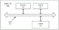
参见图5,本发明实施例还提供一种运载工具500,包括:处理器501,存储器502,总线503和通信接口504,处理器501、通信接口504和存储器502通过总线503连接;存储器502用于存储程序;处理器501用于通过总线503调用存储在存储器502中的程序,执行上述实施例的车辆控制方法。5, an embodiment of the present invention further provides a
其中,存储器502可能包含高速随机存取存储器(RAM,Random Access Memory),也可能还包括非不稳定的存储器(non-volatile memory),例如至少一个磁盘存储器。通过至少一个通信接口504(可以是有线或者无线)实现该系统网元与至少一个其他网元之间的通信连接,可以使用互联网,广域网,本地网,城域网等。The
总线503可以是ISA总线、PCI总线或EISA总线等。总线可以分为地址总线、数据总线、控制总线等。为便于表示,图5中仅用一个双向箭头表示,但并不表示仅有一根总线或一种类型的总线。The bus 503 may be an ISA bus, a PCI bus, an EISA bus, or the like. The bus can be divided into address bus, data bus, control bus and so on. For ease of representation, only one bidirectional arrow is shown in FIG. 5, but it does not mean that there is only one bus or one type of bus.
其中,存储器502用于存储程序,处理器501在接收到执行指令后,执行程序,前述本发明实施例任一实施例揭示的流过程定义的装置所执行的方法可以应用于处理器501中,或者由处理器501实现。The
处理器501可能是一种集成电路芯片,具有信号的处理能力。在实现过程中,上述方法的各步骤可以通过处理器501中的硬件的集成逻辑电路或者软件形式的指令完成。上述的处理器501可以是通用处理器,包括中央处理器(Central Processing Unit,简称CPU)、网络处理器(Network Processor,简称NP)等;还可以是数字信号处理器(DigitalSignal Processor,简称DSP)、专用集成电路(Application Specific IntegratedCircuit,简称ASIC)、现场可编程门阵列(Field-Programmable Gate Array,简称FPGA)或者其他可编程逻辑器件、分立门或者晶体管逻辑器件、分立硬件组件。可以实现或者执行本发明实施例中的公开的各方法、步骤及逻辑框图。通用处理器可以是微处理器或者该处理器也可以是任何常规的处理器等。结合本发明实施例所公开的方法的步骤可以直接体现为硬件译码处理器执行完成,或者用译码处理器中的硬件及软件模块组合执行完成。软件模块可以位于随机存储器,闪存、只读存储器,可编程只读存储器或者电可擦写可编程存储器、寄存器等本领域成熟的存储介质中。该存储介质位于存储器502,处理器501读取存储器502中的信息,结合其硬件完成上述方法的步骤。The
本发明实施例还提供了一种机器可读存储介质,机器可读存储介质存储有机器可执行指令,机器可执行指令在被处理器调用和执行时,机器可执行指令促使处理器实现如上的车辆控制方法。Embodiments of the present invention further provide a machine-readable storage medium, where the machine-readable storage medium stores machine-executable instructions, and when the machine-executable instructions are called and executed by the processor, the machine-executable instructions cause the processor to implement the above vehicle control method.
在本发明的描述中,需要说明的是,术语“第一”、“第二”、“第三”等仅用于区分描述,而不能理解为指示或暗示相对重要性。In the description of the present invention, it should be noted that the terms "first", "second", "third", etc. are only used to distinguish the description, and cannot be understood as indicating or implying relative importance.
在本申请所提供的几个实施例中,应该理解到,所揭露的系统、装置和方法,可以通过其它的方式实现。以上所描述的装置实施例仅仅是示意性的,例如,所述单元的划分,仅仅为一种逻辑功能划分,实际实现时可以有另外的划分方式,又例如,多个单元或组件可以结合或者可以集成到另一个系统,或一些特征可以忽略,或不执行。In the several embodiments provided in this application, it should be understood that the disclosed system, apparatus and method may be implemented in other manners. The apparatus embodiments described above are only illustrative. For example, the division of the units is only a logical function division. In actual implementation, there may be other division methods. For example, multiple units or components may be combined or Can be integrated into another system, or some features can be ignored, or not implemented.
所述作为分离部件说明的单元可以是或者也可以不是物理上分开的,作为单元显示的部件可以是或者也可以不是物理单元,即可以位于一个地方,或者也可以分布到多个网络单元上。可以根据实际的需要选择其中的部分或者全部单元来实现本实施例方案的目的。The units described as separate components may or may not be physically separated, and components displayed as units may or may not be physical units, that is, may be located in one place, or may be distributed to multiple network units. Some or all of the units may be selected according to actual needs to achieve the purpose of the solution in this embodiment.
另外,在本发明各个实施例中的各功能单元可以集成在一个处理单元中,也可以是各个单元单独物理存在,也可以两个或两个以上单元集成在一个单元中。In addition, each functional unit in each embodiment of the present invention may be integrated into one processing unit, or each unit may exist physically alone, or two or more units may be integrated into one unit.
所述功能如果以软件功能单元的形式实现并作为独立的产品销售或使用时,可以存储在一个处理器可执行的非易失的计算机可读取存储介质中。基于这样的理解,本发明的技术方案本质上或者说对现有技术做出贡献的部分或者该技术方案的部分可以以软件产品的形式体现出来,该计算机软件产品存储在一个存储介质中,包括若干指令用以使得一台计算机设备(可以是个人计算机,服务器,或者网络设备等)执行本发明各个实施例所述方法的全部或部分步骤。而前述的存储介质包括:U盘、移动硬盘、只读存储器(ROM,Read-Only Memory)、随机存取存储器(RAM,Random Access Memory)、磁碟或者光盘等各种可以存储程序代码的介质。The functions, if implemented in the form of software functional units and sold or used as stand-alone products, may be stored in a processor-executable non-volatile computer-readable storage medium. Based on this understanding, the technical solution of the present invention can be embodied in the form of a software product in essence, or the part that contributes to the prior art or the part of the technical solution. The computer software product is stored in a storage medium, including Several instructions are used to cause a computer device (which may be a personal computer, a server, or a network device, etc.) to execute all or part of the steps of the methods described in the various embodiments of the present invention. The aforementioned storage medium includes: U disk, mobile hard disk, Read-Only Memory (ROM, Read-Only Memory), Random Access Memory (RAM, Random Access Memory), magnetic disk or optical disk and other media that can store program codes .
最后应说明的是:以上各实施例仅用以说明本发明的技术方案,而非对其限制;尽管参照前述各实施例对本发明进行了详细的说明,本领域的普通技术人员应当理解:其依然可以对前述各实施例所记载的技术方案进行修改,或者对其中部分或者全部技术特征进行等同替换;而这些修改或者替换,并不使相应技术方案的本质脱离本发明各实施例技术方案的范围。Finally, it should be noted that the above embodiments are only used to illustrate the technical solutions of the present invention, but not to limit them; although the present invention has been described in detail with reference to the foregoing embodiments, those of ordinary skill in the art should understand that: The technical solutions described in the foregoing embodiments can still be modified, or some or all of the technical features thereof can be equivalently replaced; and these modifications or replacements do not make the essence of the corresponding technical solutions deviate from the technical solutions of the embodiments of the present invention. scope.
Claims (10)
Priority Applications (1)
| Application Number | Priority Date | Filing Date | Title |
|---|---|---|---|
| CN202010787342.8ACN111950428A (en) | 2020-08-06 | 2020-08-06 | Target obstacle identification method, device and vehicle |
Applications Claiming Priority (1)
| Application Number | Priority Date | Filing Date | Title |
|---|---|---|---|
| CN202010787342.8ACN111950428A (en) | 2020-08-06 | 2020-08-06 | Target obstacle identification method, device and vehicle |
Publications (1)
| Publication Number | Publication Date |
|---|---|
| CN111950428Atrue CN111950428A (en) | 2020-11-17 |
Family
ID=73332522
Family Applications (1)
| Application Number | Title | Priority Date | Filing Date |
|---|---|---|---|
| CN202010787342.8APendingCN111950428A (en) | 2020-08-06 | 2020-08-06 | Target obstacle identification method, device and vehicle |
Country Status (1)
| Country | Link |
|---|---|
| CN (1) | CN111950428A (en) |
Cited By (7)
| Publication number | Priority date | Publication date | Assignee | Title |
|---|---|---|---|---|
| CN111950426A (en)* | 2020-08-06 | 2020-11-17 | 东软睿驰汽车技术(沈阳)有限公司 | Target detection method, device and vehicle |
| CN112883909A (en)* | 2021-03-16 | 2021-06-01 | 东软睿驰汽车技术(沈阳)有限公司 | Surrounding box-based obstacle position detection method and device and electronic equipment |
| CN114120255A (en)* | 2021-10-29 | 2022-03-01 | 际络科技(上海)有限公司 | Target identification method and device based on laser radar speed measurement |
| WO2023142816A1 (en)* | 2022-01-26 | 2023-08-03 | 中国第一汽车股份有限公司 | Obstacle information determination method and apparatus, and electronic device and storage medium |
| CN116682092A (en)* | 2023-06-02 | 2023-09-01 | 北京全路通信信号研究设计院集团有限公司 | Identification method and system based on coordinate system and electronic equipment |
| US20230316771A1 (en)* | 2022-03-30 | 2023-10-05 | Hyundai Motor Company | Apparatus for controlling vehicle including camera and method for the same |
| CN119471633A (en)* | 2025-01-13 | 2025-02-18 | 武汉奋进智能机器有限公司 | Obstacle recognition method, device, electronic device and storage medium for overhead rail robot |
Citations (13)
| Publication number | Priority date | Publication date | Assignee | Title |
|---|---|---|---|---|
| CN106204731A (en)* | 2016-07-18 | 2016-12-07 | 华南理工大学 | A kind of multi-view angle three-dimensional method for reconstructing based on Binocular Stereo Vision System |
| US20180241923A1 (en)* | 2015-08-26 | 2018-08-23 | Zhejiang Dahua Technology Co., Ltd. | Methods and systems for traffic monitoring |
| CN108550143A (en)* | 2018-04-03 | 2018-09-18 | 长安大学 | A kind of measurement method of the vehicle length, width and height size based on RGB-D cameras |
| CN108645339A (en)* | 2018-05-14 | 2018-10-12 | 国能生物发电集团有限公司 | A kind of acquisition of bio-power plant material buttress point cloud data and calculation method of physical volume |
| CN109035322A (en)* | 2018-07-17 | 2018-12-18 | 重庆大学 | A kind of detection of obstacles and recognition methods based on binocular vision |
| US20180365503A1 (en)* | 2017-06-16 | 2018-12-20 | Baidu Online Network Technology (Beijing) Co., Ltd. | Method and Apparatus of Obtaining Obstacle Information, Device and Computer Storage Medium |
| CN109657638A (en)* | 2018-12-28 | 2019-04-19 | 百度在线网络技术(北京)有限公司 | Barrier localization method, device and terminal |
| CN109655019A (en)* | 2018-10-29 | 2019-04-19 | 北方工业大学 | Cargo volume measurement method based on deep learning and three-dimensional reconstruction |
| CN110263652A (en)* | 2019-05-23 | 2019-09-20 | 杭州飞步科技有限公司 | Laser point cloud data recognition methods and device |
| CN110807772A (en)* | 2019-11-11 | 2020-02-18 | 杭州都市高速公路有限公司 | A method for removing irrelevant point cloud based on bounding box in component size detection |
| CN111079545A (en)* | 2019-11-21 | 2020-04-28 | 上海工程技术大学 | Three-dimensional target detection method and system based on image restoration |
| CN111174697A (en)* | 2019-12-13 | 2020-05-19 | 中国南方电网有限责任公司超高压输电公司柳州局 | Stereoscopic vision image accurate measurement method based on unmanned aerial vehicle |
| CN111414848A (en)* | 2020-03-19 | 2020-07-14 | 深动科技(北京)有限公司 | Full-class 3D obstacle detection method, system and medium |
- 2020
- 2020-08-06CNCN202010787342.8Apatent/CN111950428A/enactivePending
Patent Citations (14)
| Publication number | Priority date | Publication date | Assignee | Title |
|---|---|---|---|---|
| US20180241923A1 (en)* | 2015-08-26 | 2018-08-23 | Zhejiang Dahua Technology Co., Ltd. | Methods and systems for traffic monitoring |
| CN106204731A (en)* | 2016-07-18 | 2016-12-07 | 华南理工大学 | A kind of multi-view angle three-dimensional method for reconstructing based on Binocular Stereo Vision System |
| US20180365503A1 (en)* | 2017-06-16 | 2018-12-20 | Baidu Online Network Technology (Beijing) Co., Ltd. | Method and Apparatus of Obtaining Obstacle Information, Device and Computer Storage Medium |
| CN109145680A (en)* | 2017-06-16 | 2019-01-04 | 百度在线网络技术(北京)有限公司 | A kind of method, apparatus, equipment and computer storage medium obtaining obstacle information |
| CN108550143A (en)* | 2018-04-03 | 2018-09-18 | 长安大学 | A kind of measurement method of the vehicle length, width and height size based on RGB-D cameras |
| CN108645339A (en)* | 2018-05-14 | 2018-10-12 | 国能生物发电集团有限公司 | A kind of acquisition of bio-power plant material buttress point cloud data and calculation method of physical volume |
| CN109035322A (en)* | 2018-07-17 | 2018-12-18 | 重庆大学 | A kind of detection of obstacles and recognition methods based on binocular vision |
| CN109655019A (en)* | 2018-10-29 | 2019-04-19 | 北方工业大学 | Cargo volume measurement method based on deep learning and three-dimensional reconstruction |
| CN109657638A (en)* | 2018-12-28 | 2019-04-19 | 百度在线网络技术(北京)有限公司 | Barrier localization method, device and terminal |
| CN110263652A (en)* | 2019-05-23 | 2019-09-20 | 杭州飞步科技有限公司 | Laser point cloud data recognition methods and device |
| CN110807772A (en)* | 2019-11-11 | 2020-02-18 | 杭州都市高速公路有限公司 | A method for removing irrelevant point cloud based on bounding box in component size detection |
| CN111079545A (en)* | 2019-11-21 | 2020-04-28 | 上海工程技术大学 | Three-dimensional target detection method and system based on image restoration |
| CN111174697A (en)* | 2019-12-13 | 2020-05-19 | 中国南方电网有限责任公司超高压输电公司柳州局 | Stereoscopic vision image accurate measurement method based on unmanned aerial vehicle |
| CN111414848A (en)* | 2020-03-19 | 2020-07-14 | 深动科技(北京)有限公司 | Full-class 3D obstacle detection method, system and medium |
Non-Patent Citations (3)
| Title |
|---|
| PILEUN KIM等: "SLAM-Driven Intelligent Autonomous Mobile Robot Navigation for Construction Applications", 《ADVANCED COMPUTING STRATEGIES FOR ENGINEERING》, pages 254 - 269* |
| 刘艳平: "柑橘采摘机器人障碍物识别与定位方法研究", 《中国优秀硕士学位论文全文数据库 信息科技辑》, no. 2019, pages 140 - 122* |
| 张银等: "三维激光雷达在无人车环境感知中的应用研究", 《激光与光电子学进展》, vol. 56, no. 13, pages 1 - 11* |
Cited By (7)
| Publication number | Priority date | Publication date | Assignee | Title |
|---|---|---|---|---|
| CN111950426A (en)* | 2020-08-06 | 2020-11-17 | 东软睿驰汽车技术(沈阳)有限公司 | Target detection method, device and vehicle |
| CN112883909A (en)* | 2021-03-16 | 2021-06-01 | 东软睿驰汽车技术(沈阳)有限公司 | Surrounding box-based obstacle position detection method and device and electronic equipment |
| CN114120255A (en)* | 2021-10-29 | 2022-03-01 | 际络科技(上海)有限公司 | Target identification method and device based on laser radar speed measurement |
| WO2023142816A1 (en)* | 2022-01-26 | 2023-08-03 | 中国第一汽车股份有限公司 | Obstacle information determination method and apparatus, and electronic device and storage medium |
| US20230316771A1 (en)* | 2022-03-30 | 2023-10-05 | Hyundai Motor Company | Apparatus for controlling vehicle including camera and method for the same |
| CN116682092A (en)* | 2023-06-02 | 2023-09-01 | 北京全路通信信号研究设计院集团有限公司 | Identification method and system based on coordinate system and electronic equipment |
| CN119471633A (en)* | 2025-01-13 | 2025-02-18 | 武汉奋进智能机器有限公司 | Obstacle recognition method, device, electronic device and storage medium for overhead rail robot |
Similar Documents
| Publication | Publication Date | Title |
|---|---|---|
| CN112861653B (en) | Method, system, equipment and storage medium for detecting fused image and point cloud information | |
| CN111950428A (en) | Target obstacle identification method, device and vehicle | |
| CN110147706B (en) | Obstacle recognition method and device, storage medium, and electronic device | |
| CN111950426A (en) | Target detection method, device and vehicle | |
| CN108419446B (en) | System and method for laser depth map sampling | |
| US12315165B2 (en) | Object detection method, object detection device, terminal device, and medium | |
| CN110555407B (en) | Pavement vehicle space identification method and electronic equipment | |
| CN113657224A (en) | Method, device and equipment for determining object state in vehicle-road cooperation | |
| CN112097732A (en) | Binocular camera-based three-dimensional distance measurement method, system, equipment and readable storage medium | |
| US20200082641A1 (en) | Three dimensional representation generating system | |
| CN115410167A (en) | Target detection and semantic segmentation method, device, equipment and storage medium | |
| WO2022048493A1 (en) | Camera extrinsic parameter calibration method and apparatus | |
| WO2023283929A1 (en) | Method and apparatus for calibrating external parameters of binocular camera | |
| CN113627478A (en) | Target detection method, target detection device and robot | |
| WO2022082571A1 (en) | Lane line detection method and apparatus | |
| CN112733678A (en) | Ranging method, ranging device, computer equipment and storage medium | |
| CN112654997B (en) | Lane line detection method and device | |
| CN116721162A (en) | External parameter calibration method for radar and camera, electronic equipment and storage medium | |
| CN116343165A (en) | 3D target detection system, method, terminal equipment and storage medium | |
| EP4246455A1 (en) | Method and device for detecting object and vehicle | |
| CN114596358A (en) | Object detection method and device and electronic equipment | |
| CN112364693B (en) | Binocular vision-based obstacle recognition method, device, equipment and storage medium | |
| CN114611635A (en) | Object identification method and device, storage medium and electronic device | |
| CN118149797B (en) | Grid map construction method, device, computer equipment and storage medium | |
| CN116740681B (en) | Target detection method, device, vehicle and storage medium |
Legal Events
| Date | Code | Title | Description |
|---|---|---|---|
| PB01 | Publication | ||
| PB01 | Publication | ||
| SE01 | Entry into force of request for substantive examination | ||
| SE01 | Entry into force of request for substantive examination | ||
| RJ01 | Rejection of invention patent application after publication | Application publication date:20201117 | |
| RJ01 | Rejection of invention patent application after publication |