CN111947106A - Clip-shaped position lamp and assembling method thereof - Google Patents
Clip-shaped position lamp and assembling method thereofDownload PDFInfo
- Publication number
- CN111947106A CN111947106ACN202010854595.2ACN202010854595ACN111947106ACN 111947106 ACN111947106 ACN 111947106ACN 202010854595 ACN202010854595 ACN 202010854595ACN 111947106 ACN111947106 ACN 111947106A
- Authority
- CN
- China
- Prior art keywords
- light guide
- light
- plate
- lens
- guide section
- Prior art date
- Legal status (The legal status is an assumption and is not a legal conclusion. Google has not performed a legal analysis and makes no representation as to the accuracy of the status listed.)
- Granted
Links
Images


Classifications
- F—MECHANICAL ENGINEERING; LIGHTING; HEATING; WEAPONS; BLASTING
- F21—LIGHTING
- F21S—NON-PORTABLE LIGHTING DEVICES; SYSTEMS THEREOF; VEHICLE LIGHTING DEVICES SPECIALLY ADAPTED FOR VEHICLE EXTERIORS
- F21S43/00—Signalling devices specially adapted for vehicle exteriors, e.g. brake lamps, direction indicator lights or reversing lights
- F21S43/10—Signalling devices specially adapted for vehicle exteriors, e.g. brake lamps, direction indicator lights or reversing lights characterised by the light source
- F21S43/19—Attachment of light sources or lamp holders
- F—MECHANICAL ENGINEERING; LIGHTING; HEATING; WEAPONS; BLASTING
- F21—LIGHTING
- F21S—NON-PORTABLE LIGHTING DEVICES; SYSTEMS THEREOF; VEHICLE LIGHTING DEVICES SPECIALLY ADAPTED FOR VEHICLE EXTERIORS
- F21S43/00—Signalling devices specially adapted for vehicle exteriors, e.g. brake lamps, direction indicator lights or reversing lights
- F21S43/20—Signalling devices specially adapted for vehicle exteriors, e.g. brake lamps, direction indicator lights or reversing lights characterised by refractors, transparent cover plates, light guides or filters
- F21S43/235—Light guides
- F21S43/236—Light guides characterised by the shape of the light guide
- F21S43/237—Light guides characterised by the shape of the light guide rod-shaped
- F—MECHANICAL ENGINEERING; LIGHTING; HEATING; WEAPONS; BLASTING
- F21—LIGHTING
- F21S—NON-PORTABLE LIGHTING DEVICES; SYSTEMS THEREOF; VEHICLE LIGHTING DEVICES SPECIALLY ADAPTED FOR VEHICLE EXTERIORS
- F21S43/00—Signalling devices specially adapted for vehicle exteriors, e.g. brake lamps, direction indicator lights or reversing lights
- F21S43/20—Signalling devices specially adapted for vehicle exteriors, e.g. brake lamps, direction indicator lights or reversing lights characterised by refractors, transparent cover plates, light guides or filters
- F21S43/235—Light guides
- F21S43/242—Light guides characterised by the emission area
- F21S43/245—Light guides characterised by the emission area emitting light from one or more of its major surfaces
- F—MECHANICAL ENGINEERING; LIGHTING; HEATING; WEAPONS; BLASTING
- F21—LIGHTING
- F21S—NON-PORTABLE LIGHTING DEVICES; SYSTEMS THEREOF; VEHICLE LIGHTING DEVICES SPECIALLY ADAPTED FOR VEHICLE EXTERIORS
- F21S43/00—Signalling devices specially adapted for vehicle exteriors, e.g. brake lamps, direction indicator lights or reversing lights
- F21S43/20—Signalling devices specially adapted for vehicle exteriors, e.g. brake lamps, direction indicator lights or reversing lights characterised by refractors, transparent cover plates, light guides or filters
- F21S43/235—Light guides
- F21S43/249—Light guides with two or more light sources being coupled into the light guide
- F—MECHANICAL ENGINEERING; LIGHTING; HEATING; WEAPONS; BLASTING
- F21—LIGHTING
- F21S—NON-PORTABLE LIGHTING DEVICES; SYSTEMS THEREOF; VEHICLE LIGHTING DEVICES SPECIALLY ADAPTED FOR VEHICLE EXTERIORS
- F21S43/00—Signalling devices specially adapted for vehicle exteriors, e.g. brake lamps, direction indicator lights or reversing lights
- F21S43/20—Signalling devices specially adapted for vehicle exteriors, e.g. brake lamps, direction indicator lights or reversing lights characterised by refractors, transparent cover plates, light guides or filters
- F21S43/27—Attachment thereof
- F—MECHANICAL ENGINEERING; LIGHTING; HEATING; WEAPONS; BLASTING
- F21—LIGHTING
- F21S—NON-PORTABLE LIGHTING DEVICES; SYSTEMS THEREOF; VEHICLE LIGHTING DEVICES SPECIALLY ADAPTED FOR VEHICLE EXTERIORS
- F21S45/00—Arrangements within vehicle lighting devices specially adapted for vehicle exteriors, for purposes other than emission or distribution of light
- F21S45/40—Cooling of lighting devices
- F21S45/47—Passive cooling, e.g. using fins, thermal conductive elements or openings
- F—MECHANICAL ENGINEERING; LIGHTING; HEATING; WEAPONS; BLASTING
- F21—LIGHTING
- F21V—FUNCTIONAL FEATURES OR DETAILS OF LIGHTING DEVICES OR SYSTEMS THEREOF; STRUCTURAL COMBINATIONS OF LIGHTING DEVICES WITH OTHER ARTICLES, NOT OTHERWISE PROVIDED FOR
- F21V17/00—Fastening of component parts of lighting devices, e.g. shades, globes, refractors, reflectors, filters, screens, grids or protective cages
- F21V17/10—Fastening of component parts of lighting devices, e.g. shades, globes, refractors, reflectors, filters, screens, grids or protective cages characterised by specific fastening means or way of fastening
- F21V17/12—Fastening of component parts of lighting devices, e.g. shades, globes, refractors, reflectors, filters, screens, grids or protective cages characterised by specific fastening means or way of fastening by screwing
- F—MECHANICAL ENGINEERING; LIGHTING; HEATING; WEAPONS; BLASTING
- F21—LIGHTING
- F21V—FUNCTIONAL FEATURES OR DETAILS OF LIGHTING DEVICES OR SYSTEMS THEREOF; STRUCTURAL COMBINATIONS OF LIGHTING DEVICES WITH OTHER ARTICLES, NOT OTHERWISE PROVIDED FOR
- F21V17/00—Fastening of component parts of lighting devices, e.g. shades, globes, refractors, reflectors, filters, screens, grids or protective cages
- F21V17/10—Fastening of component parts of lighting devices, e.g. shades, globes, refractors, reflectors, filters, screens, grids or protective cages characterised by specific fastening means or way of fastening
- F21V17/16—Fastening of component parts of lighting devices, e.g. shades, globes, refractors, reflectors, filters, screens, grids or protective cages characterised by specific fastening means or way of fastening by deformation of parts; Snap action mounting
- F21V17/164—Fastening of component parts of lighting devices, e.g. shades, globes, refractors, reflectors, filters, screens, grids or protective cages characterised by specific fastening means or way of fastening by deformation of parts; Snap action mounting the parts being subjected to bending, e.g. snap joints
- F—MECHANICAL ENGINEERING; LIGHTING; HEATING; WEAPONS; BLASTING
- F21—LIGHTING
- F21W—INDEXING SCHEME ASSOCIATED WITH SUBCLASSES F21K, F21L, F21S and F21V, RELATING TO USES OR APPLICATIONS OF LIGHTING DEVICES OR SYSTEMS
- F21W2103/00—Exterior vehicle lighting devices for signalling purposes
- F21W2103/10—Position lights
- F—MECHANICAL ENGINEERING; LIGHTING; HEATING; WEAPONS; BLASTING
- F21—LIGHTING
- F21W—INDEXING SCHEME ASSOCIATED WITH SUBCLASSES F21K, F21L, F21S and F21V, RELATING TO USES OR APPLICATIONS OF LIGHTING DEVICES OR SYSTEMS
- F21W2107/00—Use or application of lighting devices on or in particular types of vehicles
- F21W2107/10—Use or application of lighting devices on or in particular types of vehicles for land vehicles
- F—MECHANICAL ENGINEERING; LIGHTING; HEATING; WEAPONS; BLASTING
- F21—LIGHTING
- F21Y—INDEXING SCHEME ASSOCIATED WITH SUBCLASSES F21K, F21L, F21S and F21V, RELATING TO THE FORM OR THE KIND OF THE LIGHT SOURCES OR OF THE COLOUR OF THE LIGHT EMITTED
- F21Y2115/00—Light-generating elements of semiconductor light sources
- F21Y2115/10—Light-emitting diodes [LED]
Landscapes
- Engineering & Computer Science (AREA)
- General Engineering & Computer Science (AREA)
- Securing Globes, Refractors, Reflectors Or The Like (AREA)
- Planar Illumination Modules (AREA)
Abstract
Translated fromChinese
Description
Translated fromChinese技术领域technical field
本发明涉及汽车车灯技术领域,尤其是涉及一种回型位置灯及其组装方法。The invention relates to the technical field of automobile lamps, in particular to a return-type position lamp and an assembling method thereof.
背景技术Background technique
位置灯是汽车灯具中的重要部分,位置灯用于显示车辆的存在与车辆的宽度。随着汽车工业的快速发展,汽车位置灯的光源从传统的卤素灯泡发展为LED光源,LED光源具有发光面积小,光通量大,节能等特点。目前市场上的位置灯的照明方式主要采用LED直射和乳白色内配光镜,采用这种照明方式,LED灯珠数量较多点亮效果颗粒感较强,成本较高,且LED灯珠可见,影响使用过程中车辆的美观性。Position lights are an important part of automotive lighting, and position lights are used to display the presence of the vehicle and the width of the vehicle. With the rapid development of the automobile industry, the light source of the automobile position lamp has developed from the traditional halogen bulb to the LED light source. The LED light source has the characteristics of small luminous area, large luminous flux, and energy saving. At present, the lighting methods of position lamps on the market mainly use LED direct light and milky white internal light distribution mirrors. With this lighting method, the number of LED lamp beads is large, the lighting effect is strong, and the cost is high, and the LED lamp beads are visible. Affect the aesthetics of the vehicle during use.
如一种在中国专利文献上公开的“一种汽车前位置灯结构”,其公告号CN203464121U,包括由柔性线路板与控制电路连接,还包括安装底座,所述安装底座设置有与所述LED发光元件对应的弹性卡位,所述LED发光元件置于该弹性卡位之中。该专利申请的位置灯的照明效果不佳,且造型常见,美观性低。For example, "a structure of an automobile front position lamp" disclosed in Chinese patent documents, the publication number of which is CN203464121U, includes a flexible circuit board connected to a control circuit, and also includes a mounting base, the mounting base is provided with the LED light-emitting The elastic latching position corresponding to the element, and the LED light-emitting element is placed in the elastic latching position. The lighting effect of the position lamp of the patent application is not good, the shape is common, and the aesthetics is low.
为此,有必要提供一种照明效果更佳,且造型新颖,成本较低,美观性高的位置灯。Therefore, it is necessary to provide a position lamp with better lighting effect, novel shape, low cost and high aesthetics.
发明内容SUMMARY OF THE INVENTION
本发明的目的在于提供一种回型位置灯及其组装方法,该回型位置灯照明效果佳,且造型新颖,成本较低,美观性高。The purpose of the present invention is to provide a return-type position lamp and an assembling method thereof. The return-type position lamp has good lighting effect, novel shape, low cost and high aesthetics.
为实现上述目的,本发明提供如下技术方案:To achieve the above object, the present invention provides the following technical solutions:
一种回型位置灯,包括主壳体、灯光结构、光导装配结构及透镜结构,所述主壳体内设有内腔部及连通内腔部的外腔部,所述灯光结构包括位置灯电路板及光导管,所述位置灯电路板安装于内腔部内,所述光导管设有第一光导段及第二光导段,所述第二光导段设于内腔部内,于位置灯电路板的上方,所述第一光导段呈匚形,第一光导段的主体设于外腔部内,第一光导段的一端伸入至内腔部内,与第二光导段连接,所述位置灯电路板上对应第二光导段设有位置灯灯片,以供位置灯灯片将光照射至第二光导段上,第二光导段将光导向第一光导段,使第一光导段亮起;所述光导装配结构设置于主壳体内,并与光导管对应安装,用以在主壳体内定位光导管;A return-type position light comprises a main casing, a lighting structure, a light guide assembly structure and a lens structure, wherein the main casing is provided with an inner cavity and an outer cavity communicating with the inner cavity, and the lighting structure includes a position light circuit board and light guide, the position light circuit board is installed in the inner cavity, the light guide is provided with a first light guide section and a second light guide section, the second light guide section is set in the inner cavity, on the position light circuit board Above, the first light guide section is indented, the main body of the first light guide section is arranged in the outer cavity, one end of the first light guide section protrudes into the inner cavity, and is connected with the second light guide section, the position lamp circuit The board is provided with a position light piece corresponding to the second light guide section, so that the position light piece irradiates the light on the second light guide section, and the second light guide section guides the light to the first light guide section, so that the first light guide section lights up; The light guide assembly structure is arranged in the main casing, and is installed correspondingly with the light guide, so as to locate the light guide in the main casing;
所述透镜结构包括导光透镜板及外透镜灯罩,所述导光透镜板安装至光导装配结构上,用以将第一光导段所亮起的灯光从主壳体内导出,所述导光透镜板采用不透光材质制成,导光透镜板设有第一遮光部,第一遮光部上对应第一光导段的主体开设有导光口,所述导光口的形状与第一光导段主体的形状相匹配,所述导光口上设有内透镜条,用以将第一光导段所亮起的灯光导向外透镜灯罩;所述外透镜灯罩安装至外腔部的腔口上,将光对外照射。The lens structure includes a light guide lens plate and an outer lens lampshade. The light guide lens plate is mounted on the light guide assembly structure to guide the light illuminated by the first light guide segment from the main casing. The light guide lens The plate is made of opaque material, the light guide lens plate is provided with a first light shielding part, and the main body of the first light shielding part corresponding to the first light guide segment is provided with a light guide port, and the shape of the light guide port is the same as that of the first light guide segment. The shape of the main body matches, and the light guide port is provided with an inner lens strip, which is used to guide the light illuminated by the first light guide segment to the outer lens lampshade; External exposure.
作为本发明进一步技术方案:所述光导装配结构包括光导支架底板及光导遮光板,所述光导支架底板的一端伸入至内腔部内,另一端设于外腔部内,所述光导支架底板上设有与第一光导段对应的定位槽,以供第一光导段容置于定位槽上;所述光导遮光板安装至光导支架底板上,光导遮光板设有光导定位部,所述光导定位部上对应定位槽设有定位卡口,以供光导遮光板安装至光导支架底板上后,定位卡口对应卡合第一光导段。As a further technical solution of the present invention, the light guide assembly structure includes a light guide support base plate and a light guide shading plate, one end of the light guide support base plate extends into the inner cavity portion, and the other end is arranged in the outer cavity portion, and the light guide support base plate is provided with There is a positioning groove corresponding to the first light guide section, so that the first light guide section can be accommodated in the positioning groove; the light guide light shielding plate is installed on the bottom plate of the light guide bracket, and the light guide light shielding plate is provided with a light guide positioning part, the light guide positioning part The upper corresponding positioning slot is provided with a positioning bayonet, so that after the light guide shading plate is installed on the bottom plate of the light guide bracket, the positioning bayonet is correspondingly engaged with the first light guide segment.
作为本发明进一步技术方案:所述光导支架底板的周缘上设有若干第一连接块,所述光导遮光板对应第一连接块设有第二连接块,通过第一螺栓依次穿过第二连接块与第一连接块连接至主壳体内,将光导支架底板与光导遮光板连接,并安装至主壳体内。As a further technical solution of the present invention, a plurality of first connection blocks are arranged on the periphery of the bottom plate of the light guide bracket, and the light guide shading plate is provided with a second connection block corresponding to the first connection block, and the first bolts pass through the second connection blocks in sequence. The block and the first connecting block are connected into the main casing, connect the light guide bracket bottom plate with the light guide shading plate, and are installed in the main casing.
作为本发明进一步技术方案:所述光导支架底板上设有若干第一连接孔,所述光导遮光板对应第一连接孔设有第二连接孔,通过第二螺栓依次穿过第二连接孔与第一连接孔连接至主壳体内,将光导支架底板与光导遮光板连接,并安装至主壳体内。As a further technical solution of the present invention, a plurality of first connection holes are arranged on the bottom plate of the light guide bracket, and a second connection hole is arranged on the light guide shading plate corresponding to the first connection hole. The first connection hole is connected to the main casing, the bottom plate of the light guide bracket is connected to the light guide shading plate, and is installed in the main casing.
作为本发明进一步技术方案:所述光导支架底板的周缘上设有若干装配块,所述装配块上开设有插销口或扣装口,所述导光透镜板上对应装配块设有插销件或扣装件,以供导光透镜板安装至光导装配结构上时,导光透镜板通过插销件或扣装件与光导支架底板上的插销口或扣装口对应安装。As a further technical solution of the present invention: a plurality of assembly blocks are arranged on the periphery of the bottom plate of the light guide bracket, and the assembly blocks are provided with plug openings or buckle installation openings, and the corresponding assembly blocks on the light guide lens board are provided with plug parts or A fastener is used for installing the light guide lens plate on the light guide assembly structure, and the light guide lens plate is installed correspondingly to the latch port or the fastener port on the bottom plate of the light guide bracket through the latch or the fastener.
作为本发明进一步技术方案:所述光导支架底板与光导遮光板上均开设有通孔,所述光导支架底板与光导遮光板安装至主壳体内时,光导支架底板与光导遮光板上的通孔呈一直线,所述主壳体内对应通孔设有第一装配孔,所述导光透镜板对应通孔设有第二装配孔,以供第三螺栓从主壳体外依次穿过第一装配孔、通孔及第二装配孔,从而安装导光透镜板。As a further technical solution of the present invention: the light guide bracket base plate and the light guide shading plate are both provided with through holes, and when the light guide bracket base plate and the light guide shading plate are installed in the main casing, the through holes on the light guide bracket base plate and the light guide shading plate In a straight line, the corresponding through hole in the main casing is provided with a first assembly hole, and the light guide lens plate is provided with a second assembly hole corresponding to the through hole, so that the third bolt can pass through the first assembly in sequence from the outside of the main casing holes, through holes and second assembling holes, so as to install the light guide lens plate.
作为本发明进一步技术方案:所述第一光导段连接第二光导段的一端呈弧形,所述第二光导段呈与第一光导段相匹配的匚形,第二光导段与第一光导段连接的一端为相对设置的两根连接臂,连接臂呈弧形,所述第二光导段的另一端设于位置灯灯片的上方。As a further technical solution of the present invention, one end of the first light guide section connected to the second light guide section is in an arc shape, the second light guide section is in an indented shape that matches the first light guide section, and the second light guide section is connected to the first light guide section. One end of the segment connection is two oppositely arranged connecting arms, the connecting arms are arc-shaped, and the other end of the second light guide segment is arranged above the position light sheet.
作为本发明进一步技术方案:所述位置灯灯片共有两片,所述第二光导段的另一端与每一连接臂的连接处形成一入光口,每一位置灯灯片对应设置于一入光口的下方。As a further technical solution of the present invention, there are two pieces of the position light piece, the other end of the second light guide section and each connecting arm form a light entrance, and each position light piece is correspondingly arranged on a below the light entrance.
作为本发明进一步技术方案:所述灯光结构包括散热安装座,所述散热安装座安装于内腔部内,所述位置灯电路板安装于散热安装座上,通过散热安装座对位置灯电路板散热。As a further technical solution of the present invention: the lighting structure includes a heat dissipation mounting seat, the heat dissipation mounting seat is installed in the inner cavity, the position light circuit board is installed on the heat dissipation mounting seat, and the position light circuit board is dissipated through the heat dissipation mounting seat. .
另外,本发明有必要提供一种所述回型位置灯的组装方法。In addition, it is necessary for the present invention to provide an assembly method of the retro-type position light.
一种回型位置灯的组装方法,包括以下步骤:A method for assembling a return-type position light, comprising the following steps:
步骤1:将位置灯电路板安装至散热安装座上,再将组装后的两者一同安装至主壳体的内腔部内;Step 1: Install the position light circuit board on the heat dissipation mounting seat, and then install the assembled two together into the inner cavity of the main casing;
步骤2:将光导装配结构与光导管对应组装,光导支架底板设置至光导管的下方,将第一光导段容置于定位槽上,光导遮光板安装至光导管的上方,定位卡口对应卡合第一光导段,随后,光导支架底板与光导遮光板安装至主壳体内,使第二光导段设置至内腔部内,位于位置灯电路板的位置灯灯片上方;Step 2: Assemble the light guide assembly structure corresponding to the light guide, set the base plate of the light guide bracket to the bottom of the light guide, accommodate the first light guide segment on the positioning groove, install the light guide shading plate above the light guide, and locate the bayonet corresponding to the card The first light guide section is combined, and then, the light guide bracket bottom plate and the light guide shading plate are installed in the main casing, so that the second light guide section is arranged in the inner cavity, and is located above the position light plate of the position light circuit board;
步骤3:将导光透镜板安装至光导装配结构上,导光透镜板上的内透镜条与第一光导段的主体对应呈一直线;随后,再将外透镜灯罩安装至外腔部的腔口上。Step 3: Install the light guide lens plate on the light guide assembly structure, and the inner lens strip on the light guide lens plate corresponds to the main body of the first light guide segment in a straight line; then, install the outer lens lampshade to the cavity of the outer cavity. mouth.
与现有技术相比,本发明的有益效果是:本发明提出一种回型位置灯及其组装方法通过主壳体、灯光结构、光导装配结构及透镜结构之间的配合,能便捷地进行组装,照明效果佳,并形成独特新颖的灯光造型,成本较低,美观性高。Compared with the prior art, the beneficial effects of the present invention are as follows: the present invention proposes a return-type position light and an assembling method thereof, which can be conveniently carried out through the cooperation among the main casing, the light structure, the light guide assembly structure and the lens structure. Assembled, the lighting effect is good, and a unique and novel lighting shape is formed, with low cost and high aesthetics.
附图说明Description of drawings
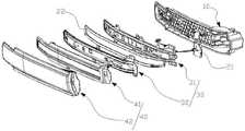
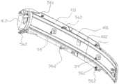
图1为回型位置灯的分解图。Figure 1 is an exploded view of the return type position light.
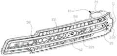
图2为灯光结构的分解图。Figure 2 is an exploded view of the light structure.
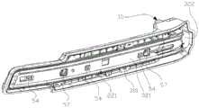
图3为光导装配结构对光导管定位的示意图。FIG. 3 is a schematic diagram of the positioning of the light guide by the light guide assembly structure.
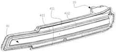
图4为灯光结构安装至主壳体内的示意图。FIG. 4 is a schematic diagram illustrating that the lighting structure is installed in the main casing.
图5为图3的结构安装至主壳体内的示意图。FIG. 5 is a schematic view of the structure of FIG. 3 being installed in the main casing.
图6为光导支架底板的示意图。FIG. 6 is a schematic diagram of the bottom plate of the light guide bracket.
图7为光导遮光板的示意图。FIG. 7 is a schematic diagram of a light guide shading plate.
图8为导光透镜板安装至图5的结构上的示意图。FIG. 8 is a schematic diagram illustrating that the light guide lens plate is mounted on the structure of FIG. 5 .
图9为导光透镜板的分解图。FIG. 9 is an exploded view of the light guide lens plate.
图10为导光透镜板的背面示意图。FIG. 10 is a schematic view of the back of the light guide lens plate.
图11为回型位置灯的整体示意图。FIG. 11 is an overall schematic diagram of the return-type position light.
图12为光导管的示意图。Figure 12 is a schematic diagram of a light pipe.
具体实施方式Detailed ways
以下结合附图对本发明的具体实施方式进行详细说明。应当理解的是,此处所描述的具体实施方式仅用于说明和解释本发明,并不用于限制本发明的保护范围。The specific embodiments of the present invention will be described in detail below with reference to the accompanying drawings. It should be understood that the specific embodiments described herein are only used to illustrate and explain the present invention, but not to limit the protection scope of the present invention.
请参阅图1,一种回型位置灯,包括主壳体10、灯光结构20、光导装配结构30及透镜结构40,,参阅图4,所述主壳体10内设有内腔部11及连通内腔部11的外腔部12,参阅图2、图4,所述灯光结构20包括位置灯电路板21及光导管22,所述位置灯电路板21安装于内腔部11内,所述光导管22设有第一光导段221及第二光导段222,所述第二光导段222设于内腔部11内,于位置灯电路板21的上方,所述第一光导段221呈匚形,第一光导段221的主体设于外腔部12内,第一光导段221的一端伸入至内腔部11内,与第二光导段222一体连接,所述位置灯电路板21上对应第二光导段222设有位置灯灯片201,以供位置灯灯片201将光照射至第二光导段222上,第二光导段222将光导向第一光导段221,使第一光导段221亮起,形成独特新颖的灯光造型;Please refer to FIG. 1, a retro-type position light, including a
参阅图3、图5,所述光导装配结构30设置于主壳体10内,并与光导管22对应安装,用以在主壳体10内定位光导管22,其包括光导支架底板31及光导遮光板32,所述光导支架底板31的一端伸入至内腔部11内,另一端设于外腔部12内,所述光导支架底板31上设有与第一光导段221对应的定位槽311,以供第一光导段221容置于定位槽311上;所述光导遮光板32安装至光导支架底板31上,光导遮光板32设有光导定位部321及设于光导定位部321一端上的光导遮光部322,所述光导定位部321上对应定位槽311设有定位卡口301,以供光导遮光板32安装至光导支架底板31上后,定位卡口301对应卡合第一光导段221,用以定位,光导遮光部322位于第二光导段222的上方,起到遮光作用;Referring to FIGS. 3 and 5 , the light
参阅图8、图9及图11,所述透镜结构40包括导光透镜板41及外透镜灯罩42,所述导光透镜板41安装至光导装配结构30上,用以将第一光导段221所亮起的灯光从主壳体10内导出,所述导光透镜板41采用不透光材质制成,对应第一光导段221设有第一遮光部411及对应第二光导段222设有第二遮光部412,所述第一遮光部411上对应第一光导段221的主体开设有导光口401,所述导光口401的形状与第一光导段221主体的形状相匹配,所述导光口401上设有内透镜条402,用以将第一光导段221所亮起的灯光导向外透镜灯罩42;所述外透镜灯罩42安装至外腔部12的腔口上,将光对外照射。8 , 9 and 11 , the
进一步地,参阅图3、图6及图7,所述光导支架底板31的周缘上设有若干第一连接块51,所述光导遮光板32对应第一连接块51设有第二连接块52,通过第一螺栓依次穿过第二连接块52与第一连接块51连接至主壳体10内,将光导支架底板31与光导遮光板32连接,并安装至主壳体10内。Further, referring to FIG. 3 , FIG. 6 and FIG. 7 , a plurality of first connecting
进一步地,所述光导支架底板31上设有若干第一连接孔53,所述光导遮光板32对应第一连接孔53设有第二连接孔54,通过第二螺栓依次穿过第二连接孔54与第一连接孔53连接至主壳体10内,将光导支架底板31与光导遮光板32连接,并安装至主壳体10内,起到加固作用。Further, the light guide
进一步地,参阅图6、图10,所述光导支架底板31的周缘上设有若干装配块55,所述装配块55上开设有插销口551或扣装口552,所述导光透镜板41上对应装配块55设有插销件561或扣装件562,以供导光透镜板41安装至光导装配结构30上时,导光透镜板41通过插销件561或扣装件562与光导支架底板31上的插销口551或扣装口552对应安装。Further, referring to FIG. 6 and FIG. 10 , a plurality of assembly blocks 55 are provided on the periphery of the light guide
进一步地,所述光导支架底板31与光导遮光板32上均开设有通孔57,所述光导支架底板31与光导遮光板32安装至主壳体10内时,光导支架底板31与光导遮光板32上的通孔57呈一直线,所述主壳体10内对应通孔57设有第一装配孔58,所述导光透镜板41对应通孔57设有第二装配孔59,以供第三螺栓从主壳体10外依次穿过第一装配孔58、通孔57及第二装配孔59,从而安装导光透镜板41。Further, the light guide
进一步地,参阅图12,所述第一光导段221连接第二光导段222的一端呈弧形,所述第二光导段222呈与第一光导段221相匹配的匚形,第二光导段222与第一光导段221连接的一端为相对设置的两根连接臂600,连接臂600呈弧形,所述第二光导段222的另一端设于位置灯灯片201的上方。Further, referring to FIG. 12 , one end of the first
进一步地,所述位置灯灯片201共有两片,所述第二光导段222的另一端与每一连接臂600的连接处形成一入光口601,每一位置灯灯片201对应设置于一入光口601的下方,以便于位置灯灯片201将光照射至第二光导段222的另一端上,从入光口601导向连接臂600,沿连接臂600导向第一光导段221。Further, there are two pieces of the position
进一步地,所述光导管22沿第一光导段221的主体设有光学齿202,第一光导段221的主体包括第一光导段221的中部及另一端,有利于光的传导。Further, the
进一步地,所述内透镜条402为带皮纹的内透镜条402,以达到磨砂效果,使得点亮效果更佳均匀有质感。Further, the
进一步地,所述灯光结构20还包括散热安装座23,所述散热安装座23安装于内腔部11内,所述位置灯电路板21安装于散热安装座23上,通过散热安装座23对位置灯电路板21散热。Further, the
所述回型位置灯的组装方法,包括以下步骤:The assembling method of the return type position light comprises the following steps:
步骤1:将位置灯电路板21安装至散热安装座23上,再将组装后的两者一同安装至主壳体10的内腔部11内;Step 1: Install the position
步骤2:将光导装配结构30与光导管22对应组装,光导支架底板31设置至光导管22的下方,将第一光导段221容置于定位槽311上,光导遮光板32安装至光导管22的上方,定位卡口301对应卡合第一光导段221,随后,光导支架底板31与光导遮光板32通过第一螺栓依次穿过第二连接块52与第一连接块51以及第二螺栓依次穿过第二连接孔54与第一连接孔53,安装至主壳体10内,并使第二光导段222设置至内腔部11内,位于位置灯电路板21的位置灯灯片201上方;Step 2: Assemble the light
步骤3:导光透镜板41通过插销件561或扣装件562与光导支架底板31上的插销口551或扣装口552对应安装,以及通过第三螺栓从主壳体10外依次穿过第一装配孔58、通孔57及第二装配孔59,将导光透镜板41安装至光导装配结构30上,导光透镜板41上的内透镜条402与第一光导段221的主体对应呈一直线;随后,再将外透镜灯罩42安装至外腔部12的腔口上,完成所述回型位置灯的组装。Step 3: The light
可以理解的,所述回型位置灯的光导过程为两件位置灯灯片201亮起,光从第二光导段222的另一端与每一连接臂600的连接处形成的入光口601均匀地沿连接臂600导向第一光导段221,第一光导段221主体上的光学齿202实现光的传导,光从第一光导段221导向导光透镜板41上的内透镜条402,所述内透镜条402为带皮纹的内透镜条402,以达到磨砂效果,使得点亮效果更佳均匀有质感,再照射至外透镜灯罩42上,对外照射,形成独特新颖的回字形灯光造型。此外,在导光过程中,通过光导遮光板32的光导遮光部322遮掩第二光导段222,起到遮光与防漏光的作用,使其组装后的回型位置灯的更为美观。It can be understood that the light-guiding process of the return-type position light is that the two pieces of position light
综上所述,本发明一种回型位置灯及其组装方法通过主壳体10、灯光结构20、光导装配结构30及透镜结构40之间的配合,能便捷地进行组装,照明效果佳,并形成独特新颖的灯光造型,成本较低,美观性高。To sum up, the retro-type position lamp and the assembling method thereof of the present invention can be assembled conveniently through the cooperation among the
只要不违背本发明创造的思想,对本发明的各种不同实施例进行任意组合,均应当视为本发明公开的内容;在本发明的技术构思范围内,对技术方案进行多种简单的变型及不同实施例进行的不违背本发明创造的思想的任意组合,均应在本发明的保护范围之内。Any combination of various embodiments of the present invention shall be regarded as the contents disclosed in the present invention as long as it does not violate the idea of the present invention; within the scope of the technical concept of the present invention, various simple modifications and Any combination of different embodiments that do not violate the idea of the present invention should fall within the protection scope of the present invention.
Claims (10)
Translated fromChinesePriority Applications (1)
| Application Number | Priority Date | Filing Date | Title |
|---|---|---|---|
| CN202010854595.2ACN111947106B (en) | 2020-08-24 | 2020-08-24 | A circular position lamp and its assembly method |
Applications Claiming Priority (1)
| Application Number | Priority Date | Filing Date | Title |
|---|---|---|---|
| CN202010854595.2ACN111947106B (en) | 2020-08-24 | 2020-08-24 | A circular position lamp and its assembly method |
Publications (2)
| Publication Number | Publication Date |
|---|---|
| CN111947106Atrue CN111947106A (en) | 2020-11-17 |
| CN111947106B CN111947106B (en) | 2025-09-26 |
Family
ID=73359232
Family Applications (1)
| Application Number | Title | Priority Date | Filing Date |
|---|---|---|---|
| CN202010854595.2AActiveCN111947106B (en) | 2020-08-24 | 2020-08-24 | A circular position lamp and its assembly method |
Country Status (1)
| Country | Link |
|---|---|
| CN (1) | CN111947106B (en) |
Cited By (2)
| Publication number | Priority date | Publication date | Assignee | Title |
|---|---|---|---|---|
| FR3128768A1 (en)* | 2021-11-01 | 2023-05-05 | Valeo Vision | MOUNTING KIT FOR LIGHTING DEVICE |
| FR3145027A1 (en)* | 2023-01-16 | 2024-07-19 | Psa Automobiles Sa | Light unit for vehicle with tubular light guide partially encapsulated in an opaque envelope |
Citations (19)
| Publication number | Priority date | Publication date | Assignee | Title |
|---|---|---|---|---|
| JP2013187176A (en)* | 2012-03-12 | 2013-09-19 | Koito Mfg Co Ltd | Vehicle lamp |
| EP2660508A2 (en)* | 2012-05-04 | 2013-11-06 | Zizala Lichtsysteme GmbH | Lighting arrangement for motor vehicles |
| US20140160778A1 (en)* | 2012-12-07 | 2014-06-12 | Koito Manufacturing Co., Ltd. | Vehicular lamp |
| CN103867968A (en)* | 2012-12-14 | 2014-06-18 | Sl株式会社 | Lamp for vehicle |
| CN104235727A (en)* | 2014-08-28 | 2014-12-24 | 马瑞利汽车零部件(芜湖)有限公司 | Novel reverse light transmission light guide type box lamp position lamp and installing method of novel reverse light transmission light guide type box lamp position lamp |
| CN204943249U (en)* | 2015-02-06 | 2016-01-06 | 上海小糸车灯有限公司 | A kind of light guide glow device of LED daytime running lamps recombination site lamp |
| JP2016157542A (en)* | 2015-02-24 | 2016-09-01 | スタンレー電気株式会社 | Vehicular lighting fixture |
| CN206268980U (en)* | 2016-09-30 | 2017-06-20 | 马瑞利汽车零部件(芜湖)有限公司 | Stereoscopic vision automobile position lamp |
| US20170267163A1 (en)* | 2016-03-16 | 2017-09-21 | Stanley Electric Co., Ltd. | Vehicle decorative lighting device and vehicle lamp |
| CN207661696U (en)* | 2017-12-21 | 2018-07-27 | 重庆长安汽车股份有限公司 | Combination tail lamp assembly |
| CN109424928A (en)* | 2017-07-18 | 2019-03-05 | 湖北华中马瑞利汽车照明有限公司 | A kind of structure being implemented in combination with taillight position lamp function by light guide item and interior len |
| JP2019139934A (en)* | 2018-02-09 | 2019-08-22 | スタンレー電気株式会社 | Lighting appliance for vehicle |
| CN209431322U (en)* | 2019-03-05 | 2019-09-24 | 南宁燎旺车灯股份有限公司 | A kind of New LED position lamp |
| CN210069734U (en)* | 2019-06-14 | 2020-02-14 | 嘉兴海拉灯具有限公司 | Optical system for car lamp and tail lamp |
| CN210740285U (en)* | 2019-11-29 | 2020-06-12 | 重庆长安汽车股份有限公司 | Automobile-used lamp and car that run through |
| CN210771928U (en)* | 2019-07-23 | 2020-06-16 | 法雷奥照明湖北技术中心有限公司 | Vehicle lamp assembly, vehicle lamp and corresponding motor vehicle |
| CN111336463A (en)* | 2020-03-04 | 2020-06-26 | 华域视觉科技(上海)有限公司 | Optical system with three-dimensional luminous effect |
| CN111473296A (en)* | 2019-01-24 | 2020-07-31 | 斯坦雷电气株式会社 | Vehicle lighting unit |
| CN212961385U (en)* | 2020-08-24 | 2021-04-13 | 马瑞利汽车照明系统(佛山)有限公司 | Clip type position lamp |
- 2020
- 2020-08-24CNCN202010854595.2Apatent/CN111947106B/enactiveActive
Patent Citations (19)
| Publication number | Priority date | Publication date | Assignee | Title |
|---|---|---|---|---|
| JP2013187176A (en)* | 2012-03-12 | 2013-09-19 | Koito Mfg Co Ltd | Vehicle lamp |
| EP2660508A2 (en)* | 2012-05-04 | 2013-11-06 | Zizala Lichtsysteme GmbH | Lighting arrangement for motor vehicles |
| US20140160778A1 (en)* | 2012-12-07 | 2014-06-12 | Koito Manufacturing Co., Ltd. | Vehicular lamp |
| CN103867968A (en)* | 2012-12-14 | 2014-06-18 | Sl株式会社 | Lamp for vehicle |
| CN104235727A (en)* | 2014-08-28 | 2014-12-24 | 马瑞利汽车零部件(芜湖)有限公司 | Novel reverse light transmission light guide type box lamp position lamp and installing method of novel reverse light transmission light guide type box lamp position lamp |
| CN204943249U (en)* | 2015-02-06 | 2016-01-06 | 上海小糸车灯有限公司 | A kind of light guide glow device of LED daytime running lamps recombination site lamp |
| JP2016157542A (en)* | 2015-02-24 | 2016-09-01 | スタンレー電気株式会社 | Vehicular lighting fixture |
| US20170267163A1 (en)* | 2016-03-16 | 2017-09-21 | Stanley Electric Co., Ltd. | Vehicle decorative lighting device and vehicle lamp |
| CN206268980U (en)* | 2016-09-30 | 2017-06-20 | 马瑞利汽车零部件(芜湖)有限公司 | Stereoscopic vision automobile position lamp |
| CN109424928A (en)* | 2017-07-18 | 2019-03-05 | 湖北华中马瑞利汽车照明有限公司 | A kind of structure being implemented in combination with taillight position lamp function by light guide item and interior len |
| CN207661696U (en)* | 2017-12-21 | 2018-07-27 | 重庆长安汽车股份有限公司 | Combination tail lamp assembly |
| JP2019139934A (en)* | 2018-02-09 | 2019-08-22 | スタンレー電気株式会社 | Lighting appliance for vehicle |
| CN111473296A (en)* | 2019-01-24 | 2020-07-31 | 斯坦雷电气株式会社 | Vehicle lighting unit |
| CN209431322U (en)* | 2019-03-05 | 2019-09-24 | 南宁燎旺车灯股份有限公司 | A kind of New LED position lamp |
| CN210069734U (en)* | 2019-06-14 | 2020-02-14 | 嘉兴海拉灯具有限公司 | Optical system for car lamp and tail lamp |
| CN210771928U (en)* | 2019-07-23 | 2020-06-16 | 法雷奥照明湖北技术中心有限公司 | Vehicle lamp assembly, vehicle lamp and corresponding motor vehicle |
| CN210740285U (en)* | 2019-11-29 | 2020-06-12 | 重庆长安汽车股份有限公司 | Automobile-used lamp and car that run through |
| CN111336463A (en)* | 2020-03-04 | 2020-06-26 | 华域视觉科技(上海)有限公司 | Optical system with three-dimensional luminous effect |
| CN212961385U (en)* | 2020-08-24 | 2021-04-13 | 马瑞利汽车照明系统(佛山)有限公司 | Clip type position lamp |
Cited By (2)
| Publication number | Priority date | Publication date | Assignee | Title |
|---|---|---|---|---|
| FR3128768A1 (en)* | 2021-11-01 | 2023-05-05 | Valeo Vision | MOUNTING KIT FOR LIGHTING DEVICE |
| FR3145027A1 (en)* | 2023-01-16 | 2024-07-19 | Psa Automobiles Sa | Light unit for vehicle with tubular light guide partially encapsulated in an opaque envelope |
Also Published As
| Publication number | Publication date |
|---|---|
| CN111947106B (en) | 2025-09-26 |
Similar Documents
| Publication | Publication Date | Title |
|---|---|---|
| CN207569721U (en) | A double-sided light-emitting ceiling panel light | |
| CN111947106A (en) | Clip-shaped position lamp and assembling method thereof | |
| CN112361297B (en) | Automobile tail lamp with multiple light effects and method for forming various light effects | |
| CN212961385U (en) | Clip type position lamp | |
| CN111412433B (en) | Motor vehicle position lamp structure and motor vehicle | |
| CN220770889U (en) | Lighting device | |
| CN218268771U (en) | lamps | |
| CN213420975U (en) | Lamplight structure for position lamp | |
| CN217532693U (en) | A lamp and vehicle | |
| CN213453470U (en) | Light guide assembly structure | |
| CN213453471U (en) | Light guide lens plate for clip-type position lamp | |
| CN206207259U (en) | A kind of light fixture, vehicle | |
| CN111486387A (en) | Double-side light emitting lamp | |
| CN221463697U (en) | Lamp with night lamp function | |
| CN222437742U (en) | Indirect lighting optical structure, lamp housing and lamp | |
| CN207179224U (en) | An LED lamp with irregular shape and uniform light emission without vignetting | |
| CN217952154U (en) | Running Light Modules, Front Combination Lights and Automotive | |
| CN212901318U (en) | Rear taillight | |
| CN218819944U (en) | Light guide piece and light guide structure thereof | |
| CN214425760U (en) | mirror headlights | |
| CN219036360U (en) | Side luminous line lamp | |
| CN210771935U (en) | Multiplexing formula marker light assembly | |
| CN209371144U (en) | Thick-walled light guide strips for car lights | |
| CN214064818U (en) | Lamp structure and sound box | |
| CN211176643U (en) | Light guide structure for solving large-area luminescence and signal lamp thereof |
Legal Events
| Date | Code | Title | Description |
|---|---|---|---|
| PB01 | Publication | ||
| PB01 | Publication | ||
| SE01 | Entry into force of request for substantive examination | ||
| SE01 | Entry into force of request for substantive examination | ||
| GR01 | Patent grant |