CN111940324A - Product appearance detection system capable of achieving efficient detection - Google Patents
Product appearance detection system capable of achieving efficient detectionDownload PDFInfo
- Publication number
- CN111940324A CN111940324ACN202010809806.0ACN202010809806ACN111940324ACN 111940324 ACN111940324 ACN 111940324ACN 202010809806 ACN202010809806 ACN 202010809806ACN 111940324 ACN111940324 ACN 111940324A
- Authority
- CN
- China
- Prior art keywords
- product
- tray
- station
- detection
- products
- Prior art date
- Legal status (The legal status is an assumption and is not a legal conclusion. Google has not performed a legal analysis and makes no representation as to the accuracy of the status listed.)
- Granted
Links
Images


Classifications
- B—PERFORMING OPERATIONS; TRANSPORTING
- B07—SEPARATING SOLIDS FROM SOLIDS; SORTING
- B07C—POSTAL SORTING; SORTING INDIVIDUAL ARTICLES, OR BULK MATERIAL FIT TO BE SORTED PIECE-MEAL, e.g. BY PICKING
- B07C5/00—Sorting according to a characteristic or feature of the articles or material being sorted, e.g. by control effected by devices which detect or measure such characteristic or feature; Sorting by manually actuated devices, e.g. switches
- B07C5/34—Sorting according to other particular properties
- B—PERFORMING OPERATIONS; TRANSPORTING
- B07—SEPARATING SOLIDS FROM SOLIDS; SORTING
- B07C—POSTAL SORTING; SORTING INDIVIDUAL ARTICLES, OR BULK MATERIAL FIT TO BE SORTED PIECE-MEAL, e.g. BY PICKING
- B07C5/00—Sorting according to a characteristic or feature of the articles or material being sorted, e.g. by control effected by devices which detect or measure such characteristic or feature; Sorting by manually actuated devices, e.g. switches
- B07C5/02—Measures preceding sorting, e.g. arranging articles in a stream orientating
- B—PERFORMING OPERATIONS; TRANSPORTING
- B07—SEPARATING SOLIDS FROM SOLIDS; SORTING
- B07C—POSTAL SORTING; SORTING INDIVIDUAL ARTICLES, OR BULK MATERIAL FIT TO BE SORTED PIECE-MEAL, e.g. BY PICKING
- B07C5/00—Sorting according to a characteristic or feature of the articles or material being sorted, e.g. by control effected by devices which detect or measure such characteristic or feature; Sorting by manually actuated devices, e.g. switches
- B07C5/36—Sorting apparatus characterised by the means used for distribution
- B07C5/361—Processing or control devices therefor, e.g. escort memory
- B07C5/362—Separating or distributor mechanisms
Landscapes
- Specific Conveyance Elements (AREA)
Abstract
Description
Translated fromChinese技术领域technical field
本发明涉及消费电子行业&SMT行业领域,具体涉及一种高效检测的产品外观检测系统。The invention relates to the field of consumer electronics industry & SMT industry, in particular to an efficient detection product appearance detection system.
背景技术Background technique
SMT贴片指的是在PCB基础上进行加工的系列工艺流程的简称,PCB(PrintedCircuit Board)为印刷电路板。SMT是表面组装技术(表面贴装技术)(Surface MountedTechnology的缩写),是电子组装行业里最流行的一种技术和工艺,对产品进行组装前首先需要对产品进行外观检测,需要在不同的检测单元上进行不同表面的检测,例如现在下表面和侧表面检测单元上对产品进行侧表面和下表面的检测,然后通过中转机械手将产品转移到上表面检测单元上对产品进行上表面的检测,现有技术中的中转机械手一般先从下表面和侧表面检测单元上吸取一个或一组产品,放到上表面检测单元上,放到上表面检测单元上,产品转移效率低。SMT patch refers to the abbreviation of a series of technological processes that are processed on the basis of PCB. PCB (Printed Circuit Board) is a printed circuit board. SMT is Surface Mount Technology (Surface Mounted Technology) (abbreviation of Surface Mounted Technology), which is the most popular technology and process in the electronic assembly industry. Different surfaces are inspected on the unit. For example, the lower surface and side surface inspection unit is used to inspect the side surface and the lower surface of the product, and then the product is transferred to the upper surface inspection unit through the transfer robot to inspect the upper surface of the product. The transfer manipulator in the prior art generally sucks one or a group of products from the lower surface and side surface detection units, puts them on the upper surface detection unit, and puts them on the upper surface detection unit, resulting in low product transfer efficiency.
发明内容SUMMARY OF THE INVENTION
本发明的目的是提供一种提高产品检测或转移效率的高效检测的产品外观检测系统。The object of the present invention is to provide a product appearance inspection system for high-efficiency inspection that improves product inspection or transfer efficiency.
为达到上述目的,本发明采用的技术方案是:一种高效检测的产品外观检测系统,包括:In order to achieve the above purpose, the technical solution adopted in the present invention is: a product appearance detection system for efficient detection, comprising:
上料机构,其用于承载料盘并对料盘进行定位;A feeding mechanism, which is used to carry and position the tray;
定位机构,其用于承载产品并对自上料机构转移来的产品进行定位;A positioning mechanism, which is used to carry the product and position the product transferred from the feeding mechanism;
外观检测机构,其包括用于承载产品并分别对自定位机构转移来的产品的不同待检测表面进行拍照检测的多个检测单元;Appearance inspection mechanism, which includes a plurality of inspection units for carrying products and respectively taking pictures and inspecting different surfaces to be inspected of the products transferred from the positioning mechanism;
缓存机构,其用于承载产品并暂存自所述外观检测机构转移来的合格产品和可修复产品;a cache mechanism, which is used for carrying products and temporarily storing qualified products and repairable products transferred from the appearance inspection mechanism;
回收机构,其用于承载料盘并放置自所述外观检测机构转移来的不合格产品并进行存储;a recycling mechanism for carrying trays and placing and storing substandard products transferred from the appearance inspection mechanism;
合格产品下料机构,其用于承载料盘并接收自缓存机构转移来的合格产品并进行存储;A qualified product unloading mechanism, which is used to carry the tray and receive and store qualified products transferred from the buffer mechanism;
可修复产品下料机构,其用于承载料盘并接收自缓存机构转移来的可修复产品并进行存储;Repairable product unloading mechanism, which is used to carry the tray and receive and store the repairable product transferred from the buffer mechanism;
其中,所述外观检测机构包括:Wherein, the appearance detection mechanism includes:
下表面和侧表面检测单元,其包括绕竖直Z轴方向可旋转的第一检测用转盘、至少两个第一图像采集装置,所述第一检测用转盘设有绕其轴线均布设置的多个第一承载部并带动每个所述第一承载部依次经过第一上料工位、至少两个第一检测工位以及至少一个第一下料工位,所述第一图像采集装置与所述第一检测工位一一对应的设置;The lower surface and side surface detection unit, which includes a first detection turntable rotatable around the vertical Z-axis direction, and at least two first image acquisition devices, the first detection turntable is provided with evenly distributed around its axis. a plurality of first bearing parts and drive each of the first bearing parts to pass through a first loading station, at least two first detection stations and at least one first unloading station in sequence, the first image acquisition device One-to-one settings corresponding to the first detection station;
上表面检测单元,其包括绕竖直Z轴方向可旋转的第二检测用转盘和至少一个第二图像采集装置,所述第二检测用转盘设有绕其轴线均布设置的多个第二承载部并带动每个所述第二承载部依次经过第二上料工位、至少一个第二检测工位以及第二下料工位,所述第二图像采集装置与所述第二检测工位一一对应的设置;The upper surface detection unit includes a second detection turntable rotatable around the vertical Z-axis direction and at least one second image acquisition device, and the second detection turntable is provided with a plurality of second detection turntables evenly arranged around its axis. The carrying part drives each of the second carrying parts to pass through the second loading station, at least one second inspection station and the second unloading station in sequence, the second image acquisition device and the second inspection station One-to-one correspondence setting;
产品移载单元,其包括绕竖直Z轴方向可旋转的移载转盘,所述移载检测转盘设有绕其轴线均布设置的两个产品料盘抓取装置并带动每个所述产品料盘抓取装置依次经过第一抓取产品工位和第二抓取产品工位,其中一个所述产品料盘抓取装置位于第一抓取产品工位并位于第一下料工位上方时,另一个所述产品料盘抓取装置位于第二抓取产品工位并位于第二上料工位上方。The product transfer unit includes a transfer turntable that is rotatable around the vertical Z-axis, and the transfer detection turntable is provided with two product tray grabbing devices evenly distributed around its axis and drives each of the products The tray grabbing device passes through the first product grabbing station and the second product grabbing station in sequence, and one of the product tray grabbing devices is located at the first product grabbing station and above the first unloading station , another of the product tray grabbing devices is located at the second grabbing product station and above the second feeding station.
进一步的,所述上料机构、所述合格产品下料机构以及所述可修复产品下料机构为相同设备,每一者包括:Further, the feeding mechanism, the qualified product feeding mechanism and the repairable product feeding mechanism are the same equipment, each of which includes:
第一升降单元,包括沿竖直Z轴方向可运动的第一升降台,所述第一升降台承载叠置的多只料盘并带动最上层料盘位于第一料盘工位;The first lifting unit includes a first lifting platform movable along the vertical Z-axis direction, the first lifting platform carries a plurality of stacked trays and drives the uppermost tray to be located at the first tray station;
第二升降单元,其包括沿竖直Z轴方向可运动第二升降台,所述第二升降台承载叠置的多只料盘并带动最上层料盘位于第二料盘工位;The second lifting unit includes a second lifting platform movable along the vertical Z-axis direction, the second lifting platform carries a plurality of stacked trays and drives the uppermost tray to be located at the second tray station;
取料单元,其包括沿水平Y轴方向可运动的治具和一次定位装置,所述治具承载单只料盘并在第一治具工位和第二治具工位之间往复,所述一次定位装置设于所述料盘的外周并将单只料盘定位在第三料盘工位;The reclaiming unit includes a jig movable along the horizontal Y-axis direction and a primary positioning device, the jig carries a single material tray and reciprocates between the first jig station and the second jig station, so The primary positioning device is arranged on the outer periphery of the material tray and locates a single material tray at the third material tray station;
料盘移载单元,其包括沿水平Y轴方向可运动并在第一料盘抓取工位和第二料盘抓取工位之间往复的料盘抓取装置,A tray transfer unit, which includes a tray grabbing device that is movable along the horizontal Y-axis direction and reciprocates between the first tray grabbing station and the second tray grabbing station,
所述治具位于第一治具工位且位于第一料盘工位上方时,所述料盘抓取装置位于第二料盘抓取工位并位于第二料盘工位上方,所述治具位于第二治具工位且位于第二料盘工位上方时,所述料盘抓取装置位于第一料盘抓取工位并位于所述第一料盘工位上方;When the fixture is located at the first fixture station and above the first tray station, the tray grab device is located at the second tray grab station and above the second tray station. When the fixture is located at the second fixture station and above the second tray station, the tray grabbing device is located at the first tray grab station and above the first tray station;
所述料盘抓取装置设有位于上方的运动系统,所述运动系统包括气缸和连杆组件,所述连杆组件包括连杆A和连杆B,所述连杆A上端与机架绕水平X轴方向可转动的连接,所述连杆A的中段部分与所述气缸的伸缩杆绕水平X轴方向可转动的连接,所述连杆A下端与所述连杆B的一端绕水平X轴方向可转动的连接,所述连杆B的另一端与所述料盘抓取装置绕水平X轴方向可转动的连接,所述气缸的伸缩杆一端背向所述第三料盘工位。The material tray grabbing device is provided with a motion system located above, the motion system includes a cylinder and a connecting rod assembly, the connecting rod assembly includes a connecting rod A and a connecting rod B, and the upper end of the connecting rod A is wound around the frame. The connection is rotatable in the direction of the horizontal X-axis, the middle section of the connecting rod A and the telescopic rod of the cylinder are rotatably connected in the direction of the horizontal X-axis, and the lower end of the connecting rod A and one end of the connecting rod B are horizontally connected. The other end of the connecting rod B is rotatably connected in the X-axis direction, and the other end of the connecting rod B is rotatably connected with the material tray grabbing device around the horizontal X-axis direction. One end of the telescopic rod of the air cylinder faces away from the third tray operator bit.
进一步的,所述气缸位于所述第一料盘工位上方,所述第三料盘工位位于第二料盘工位上方。Further, the air cylinder is located above the first tray station, and the third tray station is located above the second tray station.
进一步的,所述连杆A包括上杆段和下杆段,所述上杆段和所述下杆段形成面向所述气缸的钝角夹角,所述气缸倾斜设置,所述气缸的伸缩杆一端下垂并与所述连杆A的拐角处连接。Further, the connecting rod A includes an upper rod section and a lower rod section, the upper rod section and the lower rod section form an obtuse angle facing the cylinder, the cylinder is inclined and the telescopic rod of the cylinder is One end hangs down and connects with the corner of the connecting rod A.
进一步的,所述定位机构包括承载产品的定位台和设于产品外周并将产品定位在产品工位的二次定位装置。Further, the positioning mechanism includes a positioning table for carrying the product and a secondary positioning device arranged on the outer periphery of the product and positioning the product at the product station.
进一步的,所述缓存机构包括用于承载并暂存产品的缓存平台。Further, the cache mechanism includes a cache platform for carrying and temporarily storing products.
进一步的,所述上料机构与所述定位机构之间转移产品的机械手、所述定位机构和所述外观检测机构之间转移产品的机械手为同一上料机械手。Further, the manipulator for transferring products between the feeding mechanism and the positioning mechanism, and the manipulator for transferring products between the positioning mechanism and the appearance detection mechanism are the same feeding manipulator.
进一步的,所述外观检测机构与所述回收机构之间转移产品的机械手、所述缓存机构与所述合格产品下料机构之间转移产品的机械手、所述缓存机构与所述可修复产品下料机构之间转移产品的机械手为同一下料机械手。Further, the manipulator for transferring products between the appearance inspection mechanism and the recycling mechanism, the manipulator for transferring products between the cache mechanism and the qualified product blanking mechanism, the cache mechanism and the bottom of the repairable product. The manipulator that transfers the product between the feeding mechanisms is the same blanking manipulator.
进一步的,所述缓存机构与所述外观检测机构之间转移产品的机械手为单独设置的中转机械手。Further, the manipulator for transferring products between the cache mechanism and the appearance detection mechanism is a transfer manipulator set separately.
由于上述技术方案运用,本发明与现有技术相比具有下列优点:Due to the application of the above-mentioned technical solutions, the present invention has the following advantages compared with the prior art:
1)本发明公开的高效检测的产品外观检测系统,通过在产品移载单元设置两个产品抓取装置,两个产品抓取装置同步动作,一个进行取的动作,一个进行放的动作,大大提高了产品移载效率;1) The high-efficiency detection product appearance detection system disclosed in the present invention, by arranging two product grabbing devices in the product transfer unit, the two product grabbing devices act synchronously, one for taking and one for putting, greatly improving the performance of the product. Improve product transfer efficiency;
2)本发明公开的高效检测的产品外观检测系统,通过将料盘抓取装置的气缸设于第一升降单元或第二升降单元的上方,大大减小了上料机构、合格产品下料机构以及可修复产品下料机构沿料盘抓取装置运动方向的尺寸。2) The high-efficiency detection product appearance detection system disclosed in the present invention greatly reduces the feeding mechanism and the qualified product unloading mechanism by arranging the cylinder of the tray grabbing device above the first lifting unit or the second lifting unit. And the size of the repairable product unloading mechanism along the movement direction of the tray grabbing device.
附图说明Description of drawings
为了更清楚地说明本发明具体实施方式或现有技术中的技术方案,下面将对具体实施方式或现有技术描述中所需要使用的附图作简单的介绍,显而易见地,下面描述中的一些附图是本发明的一些实施方式,对于本领域普通技术人员来讲,在不付出创造性劳动的前提下,还可以根据这些附图获得其他的附图。In order to illustrate the specific embodiments of the present invention or the technical solutions in the prior art more clearly, the following will briefly introduce the accompanying drawings that are required in the description of the specific embodiments or the prior art. Obviously, some of the following descriptions The accompanying drawings are some embodiments of the present invention, and for those of ordinary skill in the art, other drawings can also be obtained from these drawings without creative efforts.
图1为本发明共的产品的俯视图;Fig. 1 is the top view of the total product of the present invention;
图2为本发明公开的产品的侧视图;Figure 2 is a side view of the product disclosed in the present invention;
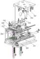
图3为本发明公开的外观检测系统的整体俯视图;3 is an overall top view of the appearance detection system disclosed in the present invention;
图4为本发明公开的上料机构、合格产品下料机构以及可修复产品下料机构的示意图;4 is a schematic diagram of a feeding mechanism, a qualified product feeding mechanism and a repairable product feeding mechanism disclosed in the present invention;
图5为本发明公开的定位机构的示意图;5 is a schematic diagram of the positioning mechanism disclosed in the present invention;
图6为本发明公开的外观检测机构的示意图;6 is a schematic diagram of the appearance detection mechanism disclosed in the present invention;
图7为图6中A处的局部放大图;Fig. 7 is the partial enlarged view of A place in Fig. 6;
图8为图6中B处的局部放大图;Fig. 8 is a partial enlarged view at B in Fig. 6;
图9缓存机构的示意图。Figure 9 is a schematic diagram of a cache mechanism.
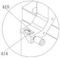
其中,100、产品;110、产品本体;120、透明标签;200、上料机构;201、第一升降台;202、第二升降台;203、治具;204、一次定位装置;205、料盘抓取装置;206、气缸;207、连杆A;208、连杆B;209、第三型腔;300、定位机构;310、定位台;320、二次定位装置;330、第四型腔;400、外观检测机构;410、下表面和侧表面检测单元;411、第一检测用转盘;412、第一图像采集装置;413、第一承载部;414、第一底壁;415、第一侧壁;420、上表面检测单元;421、第二检测用转盘;422、第二图像采集装置;423、第二承载部;424、第二底壁;415、第二侧壁;500、缓存机构;510、缓存台;520、第五型腔;600、回收机构;700、合格产品下料机构;800、可修复产品下料机构。Among them, 100, product; 110, product body; 120, transparent label; 200, feeding mechanism; 201, first lift table; 202, second lift table; 203, fixture; 204, primary positioning device; 205, material Disc grabbing device; 206, cylinder; 207, connecting rod A; 208, connecting rod B; 209, third cavity; 300, positioning mechanism; 310, positioning table; 320, secondary positioning device; 330, fourth type cavity; 400, appearance inspection mechanism; 410, lower surface and side surface inspection unit; 411, first inspection turntable; 412, first image acquisition device; 413, first bearing part; 414, first bottom wall; 415, first side wall; 420, upper surface detection unit; 421, second detection turntable; 422, second image acquisition device; 423, second bearing part; 424, second bottom wall; 415, second side wall; 500 , cache mechanism; 510, cache table; 520, fifth cavity; 600, recovery mechanism; 700, qualified product blanking mechanism; 800, repairable product blanking mechanism.
具体实施方式Detailed ways
下面将结合附图对本发明的技术方案进行清楚、完整地描述,显然,所描述的实施例是本发明一部分实施例,而不是全部的实施例。基于本发明中的实施例,本领域普通技术人员在没有做出创造性劳动前提下所获得的所有其他实施例,都属于本发明保护的范围。The technical solutions of the present invention will be clearly and completely described below with reference to the accompanying drawings. Obviously, the described embodiments are a part of the embodiments of the present invention, but not all of the embodiments. Based on the embodiments of the present invention, all other embodiments obtained by those of ordinary skill in the art without creative efforts shall fall within the protection scope of the present invention.
实施例一Example 1
参见图1至图9,如其中的图例所示,一种产品上表面、下表面以及侧表面的外观检测系统,Referring to Figures 1 to 9, as shown in the legends, an appearance inspection system for the upper surface, lower surface and side surface of a product,
产品100包括产品本体110和承载产品本体110的透明标签120,产品本体110呈圆柱状,具有上端面、下端面以及侧面,透明标签120包括重叠区和非重叠区,上端面为待检测上表面,待检测上表面朝向透明标签120的重叠区且二者贴合在一起,下端面为待检测下表面,待检测下表面背离透明标签120的重叠区,侧面远离非重叠区的一侧为待检测侧表面,The
外观检测系统包括:Appearance inspection system includes:
上料机构200,其用于承载料盘并对料盘进行定位;A
定位机构300,其用于承载产品并对自上料机构200转移来的产品进行定位;The positioning mechanism 300 is used for carrying the product and positioning the product transferred from the
外观检测机构400,其用于承载产品并对自定位机构300转移来的产品的待检测表面进行拍照检测;The appearance inspection mechanism 400 is used for carrying the product and taking pictures and inspecting the surface to be inspected of the product transferred from the positioning mechanism 300;
缓存机构500,其用于承载产品并暂存自外观检测机构400转移来的合格产品和可修复产品;The
回收机构600,其用于承载料盘并放置自所述外观检测机构转移来的不合格产品并进行存储;A
合格产品下料机构700,其用于承载料盘并接收自缓存机构500转移来的合格产品并进行存储;A qualified
可修复产品下料机构800,其用于承载料盘并接收自缓存机构500转移来的可修复产品并进行存储;Repairable
外观检测机构包括:Appearance testing institutions include:
下表面和侧表面检测单元410,其包括绕竖直Z轴方向可旋转的第一检测用转盘411、至少两个第一图像采集装置412,第一检测用转盘411设有绕其轴线均布设置的多个第一承载部413并带动每个第一承载部413依次经过第一上料工位、至少两个第一检测工位以及至少一个第一下料工位,第一图像采集装置412与第一检测工位一一对应的设置,每个第一承载部413设有用于容置产品的第一型腔,第一型腔具有第一底壁414和第一侧壁415,第一底壁414正对待检测下表面的位置设有下镂空区,第一侧壁415正对待检测侧表面的位置设有侧镂空区,透明标签120的非重叠区吸附于第一底壁414上,至少一个第一图像采集装置412为侧表面图像采集装置,侧表面图像采集装置412的镜头朝向位于其所对应的第一检测工位处第一型腔的侧镂空区,至少一个第一图像采集装置412为下表面图像采集装置,下表面图像采集装置412的镜头朝向位于其所对应的第一检测工位处第一型腔的下镂空区;The lower surface and side
上表面检测单元420,其包括绕竖直Z轴方向可旋转的第二检测用转盘421和至少一个第二图像采集装置422,第二检测用转盘421设有绕其轴线均布设置的多个第二承载部423并带动每个第二承载部依次经过第二上料工位、至少一个第二检测工位以及第二下料工位,第二图像采集装置422与第二检测工位一一对应的设置,每个第二承载部423设有用于容置产品的第二型腔,第二型腔具有承载产品的第二底壁424和定位产品的第二侧壁425,透明标签120吸附于第二底壁424上,第二图像采集装置422为上表面图像采集装置,上表面图像采集装置422的镜头朝向位于其所对应的第二检测工位处第二型腔的上端口。The upper
本实施例中优选的实施方式,上料机构200、合格产品下料机构700以及可修复产品下料机构800为相同设备,每一者包括:In a preferred implementation in this embodiment, the
第一升降单元,包括沿竖直Z轴方向可运动的第一升降台201,第一升降台201承载叠置的多只料盘并带动最上层料盘位于第一料盘工位;The first lifting unit includes a
第二升降单元,其包括沿竖直Z轴方向可运动第二升降台202,第二升降台202承载叠置的多只料盘并带动最上层料盘位于第二料盘工位;The second lifting unit includes a
取料单元,其包括沿水平Y轴方向可运动的治具203和一次定位装置204,治具203承载单只料盘并在第一治具工位和第二治具工位之间往复,一次定位装置204设于料盘的外周并将单只料盘定位在第三料盘工位;The reclaiming unit includes a
料盘移载单元,其包括沿水平Y轴方向可运动并在第一料盘抓取工位和第二料盘抓取工位之间往复的料盘抓取装置205,A tray transfer unit, which includes a
治具203位于第一治具工位且位于第一料盘工位上方时,料盘抓取装置205位于第二料盘抓取工位并位于第二料盘工位上方,治具203位于第二治具工位且位于第二料盘工位上方时,料盘抓取装置205位于第一料盘抓取工位并位于第一料盘工位上方;When the
料盘抓取装置205设有位于其上方的运动系统,运动系统包括气缸206和连杆组件,连杆组件包括连杆A207和连杆B208,连杆A207上端与机架绕与料盘抓取装置运动方向垂直的方向可转动的连接,连杆A207的中段部分与气缸206的伸缩杆绕与料盘抓取装置运动方向垂直的方向可转动的连接,连杆A207下端与连杆B208的一端绕与料盘抓取装置运动方向垂直的方向可转动的连接,连杆B208的另一端与料盘抓取装置205绕与料盘抓取装置运动方向垂直的方向可转动的连接,气缸206的伸缩杆一端背向第三料盘工位;The
料盘中设有用于容置产品的多个第三型腔209,第三型腔209与第二型腔结构相同。The tray is provided with a plurality of
本实施例中优选的实施方式,第三料盘工位位于第二料盘工位上方,气缸206位于第一料盘工位上方。In a preferred implementation of this embodiment, the third tray station is located above the second tray station, and the
本实施例中优选的实施方式,连杆A207包括上杆段和下杆段,上杆段和所述下杆段形成面向气缸206的钝角夹角,气缸206倾斜设置,气缸206的伸缩杆一端下垂并与连杆A207的拐角处连接。In a preferred implementation in this embodiment, the connecting rod A207 includes an upper rod section and a lower rod section, the upper rod section and the lower rod section form an obtuse angle facing the
本实施例中优选的实施方式,定位机构300包括承载产品的定位台310和设于产品外周并将产品定位在产品工位的二次定位装置320,定位台310上设有用于容置产品的一个或多个第四型腔330,第四型腔330与第二型腔结构相同,二次定位装置320为将产品退推入第四型腔的推板装置。In a preferred implementation in this embodiment, the positioning mechanism 300 includes a positioning table 310 for carrying the product and a
本实施例中优选的实施方式,缓存机构500包括用于承载并暂存产品的缓存平台510,缓存平台510上设有合格产品区和可修复产品区,每一者设有用于容置产品的多个第五型腔520,第五型腔520与第二型腔结构相同。In a preferred implementation in this embodiment, the
本实施例中优选的实施方式,上料机构200与定位机构300之间转移产品的机械手、定位机构300和外观检测机构400之间转移产品的机械手为同一上料机械手101。In a preferred implementation in this embodiment, the manipulator for transferring products between the
本实施例中优选的实施方式,外观检测机构400与回收机构700之间转移产品的机械手、缓存机构500与合格产品下料机构700之间转移产品的机械手、缓存机构600与可修复产品下料机构800之间转移产品的机械手为同一下料机械手102。In the preferred implementation of this embodiment, the robot for transferring products between the appearance inspection mechanism 400 and the
本实施例中优选的实施方式,下表面和侧表面检测单元410和上表面检测单元420之间转移产品的机械手为单独设置的中转机械手A430。In a preferred implementation in this embodiment, the robot for transferring products between the lower surface and side
中转机械手A430为产品移载单元,产品移载单元包括绕竖直Z轴方向可旋转的移载用转盘431,移载用转盘431设有绕其轴线均布设置的两个产品抓取装置432并带动每个产品抓取装置432依次经过第一抓取产品工位和第二抓取产品工位,其中一个产品抓取装置432位于第一抓取产品工位并位于下表面和侧表面检测单元410的下料工位上方时,另一个产品抓取装置432位于第二抓取产品工位并位于上表面检测单元420的上料工位上方。The transfer robot A430 is a product transfer unit. The product transfer unit includes a
本实施例中优选的实施方式,缓存机构500与外观检测机构400之间转移产品的机械手为单独设置的中转机械手B530。In a preferred implementation in this embodiment, the manipulator for transferring products between the
下面介绍本发明的工作过程:The working process of the present invention is introduced below:
上料工序包括如下步骤:The feeding process includes the following steps:
1.1料盘抓取装置位于第一料盘抓取工位,料盘抓取装置从第一升降台抓取最上层料盘后,第一升降台上升以使最顶层料盘位于第一料盘位置,料盘抓取装置移动至第二料盘抓取工位,治具位于第二治具工位上并位于料盘抓取装置的下方,料盘抓取装置将料盘放置到治具中,一次定位装置通过推动料盘至设定位置的方式将治具中的料盘定位到第三料盘工位;1.1 The tray grabbing device is located at the first tray grabbing station. After the tray grabbing device grabs the topmost tray from the first lifting table, the first lifting table rises so that the topmost tray is located in the first tray position, the tray grasping device moves to the second tray grasping station, the fixture is located on the second fixture station and below the tray grasping device, and the tray grasping device places the tray on the fixture , the primary positioning device positions the tray in the fixture to the third tray station by pushing the tray to the set position;
1.2、上料机械手从治具的料盘中抓取一组产品后放到定位台上;1.2. The feeding manipulator grabs a group of products from the tray of the fixture and places them on the positioning table;
1.3、当治具上料盘中的产品被上料机械手抓取完成后,料盘抓取装置从治具上抓取空料盘;1.3. After the product in the feeding tray of the fixture is grasped by the feeding manipulator, the tray grabbing device grabs the empty tray from the fixture;
1.4、治具运动至第一治具工位上并位于第一升降台上方;1.4. The jig moves to the first jig station and is located above the first lifting platform;
1.5、料盘抓取装置将空料盘放置到第二升降台上,第二升降台下降以使最上层空料盘位于第二料盘工位;1.5. The tray grabbing device places the empty tray on the second lifting platform, and the second lifting platform descends so that the uppermost empty tray is located at the second tray station;
1.6料盘抓取装置运动到第一料盘抓取工位并位于第一升降台上方,治具运动到第二治具工位并位于第二升降台上方,回到步骤1.1。1.6 The tray grabbing device moves to the first tray grabbing station and is located above the first lift table, the fixture moves to the second fixture station and is located above the second lift table, and returns to step 1.1.
定位工序包括如下步骤:The positioning process includes the following steps:
2.1、二次定位装置从初始位置开始运动,将放置到定位台上的一组产品推到第四型腔中,即将产品定位到产品工位上;2.1. The secondary positioning device starts to move from the initial position, and pushes a group of products placed on the positioning table into the fourth cavity, that is, the product is positioned on the product station;
2.2、上料机械手从第四型腔中抓取一组产品分别放置到依次到达第一上料工位的多个第一承载部的第一型腔中;2.2. The loading manipulator grabs a group of products from the fourth cavity and places them in the first cavity of multiple first bearing parts that arrive at the first loading station in turn;
2.3、二次定位装置回到初始位置,回到步骤2.1。2.3. The secondary positioning device returns to the initial position, and returns to step 2.1.
检测工序包括如下步骤The detection process includes the following steps
3.1、下表面图像采集装置和侧表面图像采集装置分别对到达其对应第一检测工位的产品进行侧表面图像采集和下表面图像采集;3.1. The lower surface image acquisition device and the side surface image acquisition device respectively carry out side surface image acquisition and lower surface image acquisition for the product arriving at its corresponding first inspection station;
3.2、中转机械手A将依次到达第一下料工位的产品分别转移到依次到达第二上料工位的第二承载部的第二型腔中;3.2. The transfer robot A transfers the products that arrive at the first unloading station in sequence to the second cavity of the second bearing part that arrives at the second loading station in sequence;
3.3、上表面图像采集装置对到达其对应第二检测工位的产品进行上表面图像采集;3.3. The upper surface image acquisition device collects the upper surface image of the product that reaches its corresponding second detection station;
缓存工序包括:The caching process includes:
4.1、中转机械手B将依次到达第二下料工位的第二承载部的第二型腔中的合格产品和可修复产品分别转移到缓存机构上,下料机械手将到达第二下料工位的不合格产品转移到回收机构;4.1. The transfer manipulator B will transfer the qualified products and repairable products in the second cavity of the second carrier part of the second blanking station in turn to the buffer mechanism, and the blanking manipulator will reach the second blanking station. of substandard products are transferred to recycling facilities;
下料工序包括如下步骤:The blanking process includes the following steps:
5.1、治具位于第一治具工位,第二升降台将最上层料盘顶升到第二料盘工位;5.1. The fixture is located at the first fixture station, and the second lifting platform lifts the uppermost tray to the second tray station;
5.2、料盘抓取装置位于第二料盘抓取工位并从第二升降台抓取最上层料盘,治具运动至第二治具工位,料盘抓取装置将料盘转移至治具,一次定位装置通过料盘推动至设定位置的方式将治具中的料盘定位到第三料盘工位;5.2. The tray grabbing device is located at the second tray grabbing station and grabs the uppermost tray from the second lifting platform. The fixture moves to the second fixture station, and the tray grabbing device transfers the tray to For the fixture, the primary positioning device positions the tray in the fixture to the third tray station by pushing the tray to the set position;
5.3、下料机械手从缓存机构的料盘中抓取一组产品后放到合格产品下料机构的料盘中或可修复产品下料机构的料盘中;5.3. The feeding manipulator grabs a group of products from the feeding tray of the cache mechanism and puts them into the feeding tray of the qualified product feeding mechanism or the feeding tray of the repairable product feeding mechanism;
5.4、当治具料盘中的产品装满后,料盘抓取装置从治具上抓取装满产品的料盘;5.4. When the product in the fixture tray is full, the tray grabbing device grabs the tray full of products from the fixture;
5.5、料盘抓取装置运动至第一料盘抓取工位并位于第一升降台上方;5.5. The tray grabbing device moves to the first tray grabbing station and is located above the first lifting platform;
5.6、料盘抓取装置将料盘放置到第一升降台上,第一升降台下降以使最上层料盘位于第一料盘工位;5.6. The tray grabbing device places the tray on the first lifting platform, and the first lifting platform descends so that the uppermost tray is located at the first tray station;
5.7、治具回到第一治具工位并位于第一升降台上方,料盘抓取装置回到第二料盘抓取工位并位于第二升降台上方,回到步骤5.1。5.7. The jig returns to the first jig station and is located above the first lifting table, the tray grabbing device returns to the second tray grabbing station and is located above the second lifting table, and returns to step 5.1.
对所公开的实施例的上述说明,使本领域专业技术人员能够实现或使用本发明。对这些实施例的多种修改对本领域的专业技术人员来说将是显而易见的,本文中所定义的一般原理可以在不脱离本发明的精神或范围的情况下,在其它实施例中实现。因此,本发明将不会被限制于本文所示的这些实施例,而是要符合与本文所公开的原理和新颖特点相一致的最宽的范围。The above description of the disclosed embodiments enables any person skilled in the art to make or use the present invention. Various modifications to these embodiments will be readily apparent to those skilled in the art, and the generic principles defined herein may be implemented in other embodiments without departing from the spirit or scope of the invention. Thus, the present invention is not intended to be limited to the embodiments shown herein, but is to be accorded the widest scope consistent with the principles and novel features disclosed herein.
Claims (9)
Translated fromChinesePriority Applications (1)
| Application Number | Priority Date | Filing Date | Title |
|---|---|---|---|
| CN202010809806.0ACN111940324B (en) | 2020-08-13 | 2020-08-13 | A Product Appearance Inspection System for Efficient Inspection |
Applications Claiming Priority (1)
| Application Number | Priority Date | Filing Date | Title |
|---|---|---|---|
| CN202010809806.0ACN111940324B (en) | 2020-08-13 | 2020-08-13 | A Product Appearance Inspection System for Efficient Inspection |
Publications (2)
| Publication Number | Publication Date |
|---|---|
| CN111940324Atrue CN111940324A (en) | 2020-11-17 |
| CN111940324B CN111940324B (en) | 2022-04-15 |
Family
ID=73332544
Family Applications (1)
| Application Number | Title | Priority Date | Filing Date |
|---|---|---|---|
| CN202010809806.0AActiveCN111940324B (en) | 2020-08-13 | 2020-08-13 | A Product Appearance Inspection System for Efficient Inspection |
Country Status (1)
| Country | Link |
|---|---|
| CN (1) | CN111940324B (en) |
Cited By (3)
| Publication number | Priority date | Publication date | Assignee | Title |
|---|---|---|---|---|
| CN113083725A (en)* | 2021-03-30 | 2021-07-09 | 昆山龙雨智能科技有限公司 | Detection device |
| CN115338151A (en)* | 2022-08-11 | 2022-11-15 | 昂坤视觉(北京)科技有限公司 | A chip detection system |
| CN115488065A (en)* | 2022-11-21 | 2022-12-20 | 苏州鼎纳自动化技术有限公司 | Detection equipment |
Citations (6)
| Publication number | Priority date | Publication date | Assignee | Title |
|---|---|---|---|---|
| DE2130792A1 (en)* | 1970-06-23 | 1971-12-30 | App Nbouw Moba N V | Self-extending gripper device |
| CN105293081A (en)* | 2015-10-27 | 2016-02-03 | 苏州和瑞科自动化科技有限公司 | Lifting type charging tray feeding and discharging equipment |
| CN207238543U (en)* | 2017-08-11 | 2018-04-17 | 苏州鼎纳自动化技术有限公司 | A kind of appearance delection device of parts |
| CN208307795U (en)* | 2018-05-17 | 2019-01-01 | 广东拓斯达科技股份有限公司 | Charging tray classification transfer |
| CN109158335A (en)* | 2018-09-25 | 2019-01-08 | 昆山鑫润利自动化科技有限公司 | Automatic cycle feeding and storing AOI detection device |
| CN110386282A (en)* | 2018-04-23 | 2019-10-29 | 乌尔曼包装系统有限责任及合伙两合公司 | It is used for transmission the transmission unit and method of blister package |
- 2020
- 2020-08-13CNCN202010809806.0Apatent/CN111940324B/enactiveActive
Patent Citations (6)
| Publication number | Priority date | Publication date | Assignee | Title |
|---|---|---|---|---|
| DE2130792A1 (en)* | 1970-06-23 | 1971-12-30 | App Nbouw Moba N V | Self-extending gripper device |
| CN105293081A (en)* | 2015-10-27 | 2016-02-03 | 苏州和瑞科自动化科技有限公司 | Lifting type charging tray feeding and discharging equipment |
| CN207238543U (en)* | 2017-08-11 | 2018-04-17 | 苏州鼎纳自动化技术有限公司 | A kind of appearance delection device of parts |
| CN110386282A (en)* | 2018-04-23 | 2019-10-29 | 乌尔曼包装系统有限责任及合伙两合公司 | It is used for transmission the transmission unit and method of blister package |
| CN208307795U (en)* | 2018-05-17 | 2019-01-01 | 广东拓斯达科技股份有限公司 | Charging tray classification transfer |
| CN109158335A (en)* | 2018-09-25 | 2019-01-08 | 昆山鑫润利自动化科技有限公司 | Automatic cycle feeding and storing AOI detection device |
Cited By (3)
| Publication number | Priority date | Publication date | Assignee | Title |
|---|---|---|---|---|
| CN113083725A (en)* | 2021-03-30 | 2021-07-09 | 昆山龙雨智能科技有限公司 | Detection device |
| CN115338151A (en)* | 2022-08-11 | 2022-11-15 | 昂坤视觉(北京)科技有限公司 | A chip detection system |
| CN115488065A (en)* | 2022-11-21 | 2022-12-20 | 苏州鼎纳自动化技术有限公司 | Detection equipment |
Also Published As
| Publication number | Publication date |
|---|---|
| CN111940324B (en) | 2022-04-15 |
Similar Documents
| Publication | Publication Date | Title |
|---|---|---|
| CN109712924B (en) | Automatic test equipment for infrared focal plane array chip | |
| CN111940324B (en) | A Product Appearance Inspection System for Efficient Inspection | |
| CN106628928B (en) | Combined test assembly line | |
| CN212944180U (en) | Automatic test equipment for electronic element | |
| CN220215796U (en) | An automatic visual inspection equipment for appearance defects of flexible circuit boards | |
| CN211102034U (en) | Automatic heat conduction block assembling and feeding machine | |
| CN110625604A (en) | Intelligent disassembly and assembly joint robot | |
| CN112676672A (en) | Automatic heat conduction block assembling and feeding machine | |
| CN114799546A (en) | Full-automatic laser drilling method and equipment | |
| CN210497311U (en) | Test equipment for PCBA board | |
| CN116519960A (en) | Mobile phone battery gum detection equipment | |
| CN215542830U (en) | Flexible screen double-sided 3D detection equipment | |
| CN215314011U (en) | Automatic online aging equipment for mobile phone | |
| CN214052610U (en) | Electronic components automated inspection packing plant | |
| CN212821192U (en) | Full-automatic testing equipment for FPC (Flexible printed Circuit) board | |
| CN213194625U (en) | Appearance detection device of a battery cell | |
| CN111940325B (en) | Appearance detection system for upper surface, lower surface and side surface of product | |
| CN218893196U (en) | Double-shaft quick material receiving and arranging device | |
| CN219179251U (en) | Chip transport detection device based on image recognition | |
| CN215893511U (en) | PCB full-size measuring machine | |
| CN114772278B (en) | Plate exposure equipment | |
| CN211997822U (en) | Glass cover plate AOI detection automatic loading and unloading equipment | |
| CN115636264A (en) | Quick material collecting and placing device with double shafts | |
| CN212597240U (en) | Automatic detection device for appearance of core block | |
| CN112830196A (en) | Automatic lens correction equipment |
Legal Events
| Date | Code | Title | Description |
|---|---|---|---|
| PB01 | Publication | ||
| PB01 | Publication | ||
| SE01 | Entry into force of request for substantive examination | ||
| SE01 | Entry into force of request for substantive examination | ||
| GR01 | Patent grant | ||
| GR01 | Patent grant | ||
| PE01 | Entry into force of the registration of the contract for pledge of patent right | ||
| PE01 | Entry into force of the registration of the contract for pledge of patent right | Denomination of invention:An Efficient Product Appearance Inspection System Effective date of registration:20221123 Granted publication date:20220415 Pledgee:Agricultural Bank of China Limited Suzhou Industrial Park sub branch Pledgor:SUZHOU DINNAR TECHNOLOGY FOR AUTOMATION Co.,Ltd. Registration number:Y2022320010715 | |
| PP01 | Preservation of patent right | ||
| PP01 | Preservation of patent right | Effective date of registration:20250820 Granted publication date:20220415 |