CN111939659A - Aerosol collecting and processing device - Google Patents
Aerosol collecting and processing deviceDownload PDFInfo
- Publication number
- CN111939659A CN111939659ACN202010757796.0ACN202010757796ACN111939659ACN 111939659 ACN111939659 ACN 111939659ACN 202010757796 ACN202010757796 ACN 202010757796ACN 111939659 ACN111939659 ACN 111939659A
- Authority
- CN
- China
- Prior art keywords
- chamber
- aerosol
- filter plate
- air inlet
- box body
- Prior art date
- Legal status (The legal status is an assumption and is not a legal conclusion. Google has not performed a legal analysis and makes no representation as to the accuracy of the status listed.)
- Granted
Links
Images


Classifications
- B—PERFORMING OPERATIONS; TRANSPORTING
- B01—PHYSICAL OR CHEMICAL PROCESSES OR APPARATUS IN GENERAL
- B01D—SEPARATION
- B01D46/00—Filters or filtering processes specially modified for separating dispersed particles from gases or vapours
- B01D46/0027—Filters or filtering processes specially modified for separating dispersed particles from gases or vapours with additional separating or treating functions
- B01D46/0028—Filters or filtering processes specially modified for separating dispersed particles from gases or vapours with additional separating or treating functions provided with antibacterial or antifungal means
- B—PERFORMING OPERATIONS; TRANSPORTING
- B01—PHYSICAL OR CHEMICAL PROCESSES OR APPARATUS IN GENERAL
- B01D—SEPARATION
- B01D46/00—Filters or filtering processes specially modified for separating dispersed particles from gases or vapours
- B01D46/10—Particle separators, e.g. dust precipitators, using filter plates, sheets or pads having plane surfaces
- B01D46/12—Particle separators, e.g. dust precipitators, using filter plates, sheets or pads having plane surfaces in multiple arrangements
- B—PERFORMING OPERATIONS; TRANSPORTING
- B01—PHYSICAL OR CHEMICAL PROCESSES OR APPARATUS IN GENERAL
- B01D—SEPARATION
- B01D53/00—Separation of gases or vapours; Recovering vapours of volatile solvents from gases; Chemical or biological purification of waste gases, e.g. engine exhaust gases, smoke, fumes, flue gases, aerosols
- B01D53/007—Separation of gases or vapours; Recovering vapours of volatile solvents from gases; Chemical or biological purification of waste gases, e.g. engine exhaust gases, smoke, fumes, flue gases, aerosols by irradiation
- B—PERFORMING OPERATIONS; TRANSPORTING
- B01—PHYSICAL OR CHEMICAL PROCESSES OR APPARATUS IN GENERAL
- B01D—SEPARATION
- B01D53/00—Separation of gases or vapours; Recovering vapours of volatile solvents from gases; Chemical or biological purification of waste gases, e.g. engine exhaust gases, smoke, fumes, flue gases, aerosols
- B01D53/34—Chemical or biological purification of waste gases
- B01D53/74—General processes for purification of waste gases; Apparatus or devices specially adapted therefor
- B01D53/77—Liquid phase processes
- B01D53/78—Liquid phase processes with gas-liquid contact
- B—PERFORMING OPERATIONS; TRANSPORTING
- B01—PHYSICAL OR CHEMICAL PROCESSES OR APPARATUS IN GENERAL
- B01D—SEPARATION
- B01D2257/00—Components to be removed
- B01D2257/91—Bacteria; Microorganisms
- B—PERFORMING OPERATIONS; TRANSPORTING
- B01—PHYSICAL OR CHEMICAL PROCESSES OR APPARATUS IN GENERAL
- B01D—SEPARATION
- B01D2259/00—Type of treatment
- B01D2259/80—Employing electric, magnetic, electromagnetic or wave energy, or particle radiation
- B01D2259/804—UV light
Landscapes
- Chemical & Material Sciences (AREA)
- Engineering & Computer Science (AREA)
- Chemical Kinetics & Catalysis (AREA)
- Environmental & Geological Engineering (AREA)
- Health & Medical Sciences (AREA)
- Analytical Chemistry (AREA)
- General Chemical & Material Sciences (AREA)
- Oil, Petroleum & Natural Gas (AREA)
- Biomedical Technology (AREA)
- Toxicology (AREA)
- Disinfection, Sterilisation Or Deodorisation Of Air (AREA)
- Apparatus For Disinfection Or Sterilisation (AREA)
Abstract
Translated fromChinese
Description
Translated fromChinese技术领域technical field
本发明涉及医疗设备领域,具体而言,涉及一种气溶胶收集处理装置。The invention relates to the field of medical equipment, in particular to an aerosol collection and processing device.
背景技术Background technique
一些传染病,如新型冠状病毒等,可能通过气溶胶的方式传播。对于如医院或其他诊疗机构等患病者出现或滞留时间较长的场所,气溶胶传播的方式不容忽视。Some infectious diseases, such as the new coronavirus, may be transmitted by means of aerosols. For places where sick people appear or stay for a long time, such as hospitals or other medical institutions, the way of aerosol transmission cannot be ignored.
然而现有技术中的气溶胶处理设备存在置办成本高、功能单一的问题。However, the aerosol treatment equipment in the prior art has the problems of high purchase cost and single function.
发明内容SUMMARY OF THE INVENTION
本发明旨在提供一种气溶胶收集处理装置,以解决现有技术中的气溶胶处理设备存在置办成本高、功能单一的问题。The present invention aims to provide an aerosol collecting and processing device to solve the problems of high purchase cost and single function of the aerosol processing equipment in the prior art.
本发明的实施例是这样实现的:The embodiments of the present invention are implemented as follows:
一种气溶胶收集处理装置,其包括:An aerosol collection and processing device, comprising:
箱体,所述箱体内部空间从上到下依次设置为气溶胶收集室、排气室、过滤室和进气室;a box body, the inner space of the box body is sequentially arranged from top to bottom as an aerosol collection chamber, an exhaust chamber, a filter chamber and an air intake chamber;
所述气溶胶收集室和所述排气室之间由上隔板分隔;所述排气室和所述过滤室之间由第二过滤板分隔;所述过滤室和所述进气室之间由第一过滤板分隔;The aerosol collection chamber and the exhaust chamber are separated by an upper partition; the exhaust chamber and the filter chamber are separated by a second filter plate; the space between the filter chamber and the intake chamber is are separated by a first filter plate;
所述气溶胶收集室连接有气溶胶收集吸管,用于收集气溶胶;The aerosol collection chamber is connected with an aerosol collection straw for collecting aerosol;
所述进气室开设有空气入口,用于空气进入;所述箱体内设有沿竖向依次穿过所述上隔板、所述第二过滤板和所述第一过滤板的通道部,所述通道部限定连通所述气溶胶收集室和所述进气室的直通道该处所述的直通道指直接连通气溶胶收集室和进气室而不连通排气室和过滤室之意,而非指该通道的曲直;The air intake chamber is provided with an air inlet for air to enter; the box is provided with a channel portion that passes through the upper partition plate, the second filter plate and the first filter plate in sequence in the vertical direction. , the channel portion defines a straight channel that communicates with the aerosol collection chamber and the air intake chamber. The straight channel described here refers to the direct connection between the aerosol collection chamber and the air intake chamber, but not between the exhaust chamber and the filter chamber. meaning, rather than the straightness of the passage;
所述进气室和/或所述第一过滤板上设有消毒设备;The air intake chamber and/or the first filter plate are provided with disinfection equipment;
所述排气室开设有排气口;The exhaust chamber is provided with an exhaust port;
所述箱体内设有风机,用以形成从空气入口和气溶胶收集吸管分别进气、并依次经过第一过滤板和第二过滤板后从排气口排气的气流循环。A fan is arranged in the box to form an air flow circulation that takes in air from the air inlet and the aerosol collecting straw respectively, and passes through the first filter plate and the second filter plate in sequence and then exhausts from the exhaust port.
本方案中的气溶胶收集处理装置使用时,启动风机以形成从气溶胶收集口和空气入口分别吸气、经过净化消毒处理后从排气口排气的确定流动方向的气流,并且在该气体流动过程中,气流依次被消毒设备消毒和被第一过滤板和第二过滤板过滤,从而实现有效的空气净化和气溶胶处理功能。When the aerosol collection and treatment device in this scheme is in use, the fan is started to form an air flow with a certain flow direction, which is inhaled from the aerosol collection port and the air inlet respectively, and exhausted from the exhaust port after purification and disinfection treatment. During the flow, the air flow is sterilized by the sterilizing equipment and filtered by the first filter plate and the second filter plate in turn, so as to achieve effective air purification and aerosol treatment functions.
在一种实施方式中:In one embodiment:
所述第一过滤板上设置有消毒液供给器,所述消毒液供给器包括用于容纳消毒液的消毒液盒和滴管,所述滴管位于第一过滤板上方,并能够将消毒液盒内的消毒液引导滴落在第一过滤板上。The first filter plate is provided with a disinfectant supply, which includes a disinfectant box for accommodating the disinfectant and a dropper, the dropper is located above the first filter plate and is capable of supplying the disinfectant. The disinfectant in the box is guided to drip onto the first filter plate.
在一种实施方式中:In one embodiment:
所述滴管上开设有多个滴液口,用以向所述第一过滤板不同位置滴液。The drip tube is provided with a plurality of drip ports for dripping liquid to different positions of the first filter plate.
在一种实施方式中:In one embodiment:
所述消毒液盒和所述滴管之间设置有能够控制两者之间连通通断的电磁阀。A solenoid valve capable of controlling the on-off of the communication between the two is arranged between the disinfectant box and the drip tube.
在一种实施方式中:In one embodiment:
所述进气室内的底板上设置有用于杀毒的紫外灯;The bottom plate in the air intake chamber is provided with an ultraviolet lamp for sterilization;
所述通道部的下端向下延伸至使其出口位于紫外灯附近。The lower end of the channel portion extends downward so that its outlet is located near the UV lamp.
在一种实施方式中:In one embodiment:
所述通道部设置于箱体一角处,并在箱体的该角处和箱体围成所述直通道。The channel part is arranged at a corner of the box body, and the corner of the box body and the box body form the straight channel.
在一种实施方式中:In one embodiment:
所述上隔板上开设有连通所述直通道的通孔,所述通孔处设置有连通管,所述连通管连通所述气溶胶收集室和所述直通道。The upper partition is provided with a through hole that communicates with the straight channel, and a communication pipe is arranged at the through hole, and the communication pipe communicates with the aerosol collection chamber and the straight channel.
在一种实施方式中:In one embodiment:
所述气溶胶收集吸管包括竖管段和连接于竖管段上端的横管段,所述横管段的末端设置为气溶胶入口;所述竖管段的下端连通所述气溶胶收集室,并且所述气溶胶收集吸管以其竖管段的下端可转动地配合连接于所述箱体的顶壁。The aerosol collection straw includes a vertical pipe section and a horizontal pipe section connected to the upper end of the vertical pipe section, the end of the horizontal pipe section is set as an aerosol inlet; the lower end of the vertical pipe section is connected to the aerosol collection chamber, and the aerosol The collection suction pipe is connected to the top wall of the box body in a rotatable manner with the lower end of the vertical pipe section.
在一种实施方式中:In one embodiment:
所述风机设置于所述排气室内,其进风口朝下对应所述第二过滤板,出风口对应所述排气口。The fan is arranged in the exhaust chamber, and the air inlet corresponds to the second filter plate downward, and the air outlet corresponds to the exhaust port.
附图说明Description of drawings
为了更清楚地说明本发明实施例的技术方案,下面将对实施例中提及之附图作简单地介绍,应当理解,以下附图仅示出了本发明的某些实施例,因此不应被看作是对范围的限定,对于本领域普通技术人员来讲,在不付出创造性劳动的前提下,还可以根据这些附图获得其他相关的附图。In order to explain the technical solutions of the embodiments of the present invention more clearly, the accompanying drawings mentioned in the embodiments will be briefly introduced below. It should be understood that the following drawings only show some embodiments of the present invention, and therefore should not be It is regarded as a limitation of the scope, and for those of ordinary skill in the art, other related drawings can also be obtained from these drawings without any creative effort.
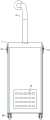
图1中示出了本发明实施例的气溶胶收集处理装置的三维视图;Figure 1 shows a three-dimensional view of an aerosol collection and processing device according to an embodiment of the present invention;
图2中示出了本发明实施例的气溶胶收集处理装置的后面视图;Figure 2 shows a rear view of the aerosol collection and processing device according to an embodiment of the present invention;
图3示出了本发明实施例的气溶胶收集处理装置的一个内部结构;Fig. 3 shows an internal structure of the aerosol collection and processing device according to the embodiment of the present invention;
图4示出了本发明实施例的气溶胶收集处理装置的另一个内部结构;Fig. 4 shows another internal structure of the aerosol collection and processing device according to the embodiment of the present invention;
图5为消毒液供给器的示意图。Figure 5 is a schematic diagram of a disinfectant supply.
图标:气溶胶收集处理装置10、箱体11、气溶胶收集室12、排气室13、过滤室14、进气室15、上隔板16、第二过滤板17、第一过滤板18、气溶胶收集吸管19、空气入口20、通道部21、直通道22、排气口23、风机24、消毒液供给器25、消毒液盒26、滴管27、滴液口28、电磁阀29、紫外灯30、底壁31、围壁32、顶盖33、搭扣34、连通管35、竖管段36、横管段37、气溶胶入口38、连接管39。Icons: aerosol collection and treatment device 10,
具体实施方式Detailed ways
为使本发明实施例的目的、技术方案和优点更加清楚,下面将结合本发明实施例中的附图,对本发明实施例中的技术方案进行清楚、完整地描述,显然,所描述的实施例是本发明一部分实施例,而不是全部的实施例。通常在此处附图中描述和示出的本发明实施例的组件可以以各种不同的配置来布置和设计。In order to make the purposes, technical solutions and advantages of the embodiments of the present invention clearer, the technical solutions in the embodiments of the present invention will be clearly and completely described below with reference to the accompanying drawings in the embodiments of the present invention. Obviously, the described embodiments These are some embodiments of the present invention, but not all embodiments. The components of the embodiments of the invention generally described and illustrated in the drawings herein may be arranged and designed in a variety of different configurations.
因此,以下对在附图中提供的本发明的实施例的详细描述并非旨在限制要求保护的本发明的范围,而是仅仅表示本发明的选定实施例。基于本发明中的实施例,本领域普通技术人员在没有做出创造性劳动前提下所获得的所有其他实施例,都属于本发明保护的范围。Thus, the following detailed description of the embodiments of the invention provided in the accompanying drawings is not intended to limit the scope of the invention as claimed, but is merely representative of selected embodiments of the invention. Based on the embodiments of the present invention, all other embodiments obtained by those of ordinary skill in the art without creative efforts shall fall within the protection scope of the present invention.
实施例Example
参见图1-图4,本实施例提出一种气溶胶收集处理装置10,其包括箱体11,箱体11内部空间从上到下依次设置为气溶胶收集室12、排气室13、过滤室14和进气室15。其中,气溶胶收集室12和排气室13之间由上隔板16分隔;排气室13和过滤室14之间由第二过滤板17分隔;过滤室14和进气室15之间由第一过滤板18分隔。气溶胶收集室12连接有气溶胶收集吸管19,用于收集气溶胶。进气室15开设有空气入口20,用于空气进入;箱体11内设有沿竖向依次穿过上隔板16、第二过滤板17和第一过滤板18的通道部21,通道部21限定连通气溶胶收集室12和进气室15的直通道22。该处的直通道22指直接连通气溶胶收集室12和进气室15而不连通排气室13和过滤室14之意,而非指该通道的曲直。进气室15和/或第一过滤板18上设有消毒设备。排气室13开设有排气口23。箱体11内设有风机24,用以形成从空气入口20和气溶胶收集吸管19分别进气、并依次经过第一过滤板18和第二过滤板17后从排气口23排气的气流循环。可选地,风机24设置于排气室13内,其进风口朝下对应第二过滤板17,出风口对应排气口23。1-4, the present embodiment proposes an aerosol collection and processing device 10, which includes a
本方案中的气溶胶收集处理装置10使用时,启动风机24以形成从气溶胶收集口和空气入口20分别吸气、经过净化消毒处理后从排气口23排气的确定流动方向的气流,并且在该气体流动过程中,气流依次被消毒设备消毒和被第一过滤板18和第二过滤板17过滤,从而实现有效的空气净化和气溶胶处理功能。When the aerosol collection and treatment device 10 in this scheme is in use, the
本方案中的气溶胶收集处理装置10通过合理设计结构布置和气流规划,能够在方便使用的基础上,同时实现空气净化和气溶胶处理,从而降低了单独购置的成本。The aerosol collection and treatment device 10 in this solution can realize air purification and aerosol treatment at the same time on the basis of convenient use through rational design of structural arrangement and airflow planning, thereby reducing the cost of separate purchase.
本实施例中,第一过滤板18上设置有消毒液供给器25,配合参加图5,消毒液供给器25包括用于容纳消毒液的消毒液盒26和滴管27,滴管27位于第一过滤板18上方,并能够将消毒液盒26内的消毒液引导滴落在第一过滤板18上。可选地,滴管27上开设有多个滴液口28,用以向第一过滤板18不同位置滴液。本实施例中,通过滴管27将消毒液滴落在第一过滤板18上的方式,可给第一过滤板18以消毒液消毒的功能,如此通过第一过滤板18或被过滤板过滤下来病毒、有害细菌等将被消毒液杀死,使得向后流动空气的安全性和清洁性提高。In the present embodiment, the
本实施例中,消毒液盒26和滴管27之间设置有能够控制两者之间连通通断的电磁阀29。电磁阀29的通断控制可采用现有常用的技术。另外,还可设置时间继电器控制滴管27滴液时间间隔等,来实现更智能地控制。该时间控制方式亦可参见现有的时间控制方式。In the present embodiment, a
本实施例中,进气室15内的底板上设置有用于杀毒的紫外灯30;通道部21的下端向下延伸至使其出口位于紫外灯30附近。如此,从通道部21的直通道22通下的气流将可靠地经过紫外灯30,气流被紫外灯30充分照射和杀毒,能够确保杀毒效率,减小后续对消毒液杀毒性能的要求。In this embodiment, an
本实施例中的箱体11主要作用为围成各腔室,并为各结构提供安装基础和支撑。可选地,箱体11包括底壁31、四个围壁32和顶盖33,顶盖33通过搭扣34可拆卸地连接于围壁32,以在需要时打开。可选地,通道部21设置于箱体11一角处,并在箱体11的该角处和箱体11围成直通道22。例如通道部21可以是L型截面的长条件,其两边分别贴合连接于箱体11的两个侧壁内表面。The main function of the
本实施例中,上隔板16上开设有连通直通道22的通孔,通孔处设置有连通管35,连通管35连通气溶胶收集室12和直通道22。In this embodiment, the
本实施例中的气溶胶收集吸管19包括竖管段36和连接于竖管段36上端的横管段37,横管段37的末端设置为气溶胶入口38;竖管段36的下端连通气溶胶收集室12,并且气溶胶收集吸管19以其竖管段36的下端可转动地配合连接于箱体11的顶壁。可选地,在顶盖33中间位置转动连接一连接管39,该连接管39贯通顶盖33并伸出气溶胶收集室12之外;而竖管段36的下端调节于连接管39,以使气溶胶收集吸管19能够周向转动以改变朝向。The aerosol
本实施例中的气溶胶收集处理装置10的底部还设置行走轮40,以方便本气溶胶收集处理装置10的转移。The bottom of the aerosol collecting and processing device 10 in this embodiment is also provided with a running
以上仅为本发明的优选实施例而已,并不用于限制本发明,对于本领域的技术人员来说,本发明可以有各种更改和变化。凡在本发明的精神和原则之内,所作的任何修改、等同替换、改进等,均应包含在本发明的保护范围之内。The above are only preferred embodiments of the present invention, and are not intended to limit the present invention. For those skilled in the art, the present invention may have various modifications and changes. Any modification, equivalent replacement, improvement, etc. made within the spirit and principle of the present invention shall be included within the protection scope of the present invention.
Claims (9)
Priority Applications (1)
| Application Number | Priority Date | Filing Date | Title |
|---|---|---|---|
| CN202010757796.0ACN111939659B (en) | 2020-07-31 | 2020-07-31 | Aerosol collection and processing device |
Applications Claiming Priority (1)
| Application Number | Priority Date | Filing Date | Title |
|---|---|---|---|
| CN202010757796.0ACN111939659B (en) | 2020-07-31 | 2020-07-31 | Aerosol collection and processing device |
Publications (2)
| Publication Number | Publication Date |
|---|---|
| CN111939659Atrue CN111939659A (en) | 2020-11-17 |
| CN111939659B CN111939659B (en) | 2025-03-18 |
Family
ID=73338956
Family Applications (1)
| Application Number | Title | Priority Date | Filing Date |
|---|---|---|---|
| CN202010757796.0AActiveCN111939659B (en) | 2020-07-31 | 2020-07-31 | Aerosol collection and processing device |
Country Status (1)
| Country | Link |
|---|---|
| CN (1) | CN111939659B (en) |
Citations (6)
| Publication number | Priority date | Publication date | Assignee | Title |
|---|---|---|---|---|
| DE20205642U1 (en)* | 2001-11-20 | 2002-07-25 | Maier, Max, 71636 Ludwigsburg | Extractor device, in particular extractor hood |
| US20080072764A1 (en)* | 2006-09-22 | 2008-03-27 | Chane-Yu Lai | Uniform aerosol deposit sampling device |
| US20080105120A1 (en)* | 2006-11-03 | 2008-05-08 | Mark Simpson Berry | Method and apparatus for the enhanced removal of aerosols from a gas stream |
| WO2014070140A1 (en)* | 2012-10-30 | 2014-05-08 | Hewlett-Packard Development Company, L.P. | Ink aerosol filtration |
| CN109464871A (en)* | 2018-12-18 | 2019-03-15 | 江西众安职业危害评价检测有限公司 | Laboratory aerosol removal system |
| CN212417294U (en)* | 2020-07-31 | 2021-01-29 | 成都市萨尼医疗器械有限公司 | Aerosol collecting and processing device |
- 2020
- 2020-07-31CNCN202010757796.0Apatent/CN111939659B/enactiveActive
Patent Citations (6)
| Publication number | Priority date | Publication date | Assignee | Title |
|---|---|---|---|---|
| DE20205642U1 (en)* | 2001-11-20 | 2002-07-25 | Maier, Max, 71636 Ludwigsburg | Extractor device, in particular extractor hood |
| US20080072764A1 (en)* | 2006-09-22 | 2008-03-27 | Chane-Yu Lai | Uniform aerosol deposit sampling device |
| US20080105120A1 (en)* | 2006-11-03 | 2008-05-08 | Mark Simpson Berry | Method and apparatus for the enhanced removal of aerosols from a gas stream |
| WO2014070140A1 (en)* | 2012-10-30 | 2014-05-08 | Hewlett-Packard Development Company, L.P. | Ink aerosol filtration |
| CN109464871A (en)* | 2018-12-18 | 2019-03-15 | 江西众安职业危害评价检测有限公司 | Laboratory aerosol removal system |
| CN212417294U (en)* | 2020-07-31 | 2021-01-29 | 成都市萨尼医疗器械有限公司 | Aerosol collecting and processing device |
Non-Patent Citations (1)
| Title |
|---|
| 梅瑛;李瑞琴;: "荧光素钠气溶胶发生装置的设计", 山西化工, no. 03, 15 June 2007 (2007-06-15)* |
Also Published As
| Publication number | Publication date |
|---|---|
| CN111939659B (en) | 2025-03-18 |
Similar Documents
| Publication | Publication Date | Title |
|---|---|---|
| CN111486529B (en) | A kind of air directional transmission device and air sterilization system in pathogenic microorganism prevention and control ward area | |
| CN210485934U (en) | Elevator car air purification degerming system device | |
| CN213077906U (en) | Air purification equipment | |
| CN204219462U (en) | Air disinfection device | |
| CN212417294U (en) | Aerosol collecting and processing device | |
| CN209901027U (en) | An indoor air purification device | |
| CN111939659A (en) | Aerosol collecting and processing device | |
| CN207050114U (en) | Air cleaning unit | |
| CN112146195A (en) | Air circulation equipment with epidemic prevention and disinfection functions for intelligent supermarket | |
| CN208278307U (en) | A kind of refrigeration equipment of ship cold storage | |
| CN216522109U (en) | Ultra-clean sterilization device for dust-free room | |
| CN108567990A (en) | High efficient cryogenic hinders photon energy sterilizing filter | |
| CN214094790U (en) | A disinfection ventilation unit that takes a breath for infectious department | |
| CN105214124B (en) | Medical attraction system purifies tapping equipment | |
| CN213421362U (en) | Air treatment device for pathology experiments | |
| KR102268886B1 (en) | Gas clean apparatus | |
| CN209917584U (en) | Department of respiration uses gaseous purifier | |
| CN220750309U (en) | Fresh air purifying and circulating device for operating room | |
| CN114396684A (en) | High movable medical science sampling workstation of security | |
| KR20180045272A (en) | Sterilizing apparatus using electric power | |
| CN217568184U (en) | Multifunctional waste gas treatment system for integrated laboratory | |
| CN215112662U (en) | Industrial waste gas purification treatment device | |
| CN218495209U (en) | Dynamic disinfection system for central air-conditioning pipeline | |
| CN211667940U (en) | Compound sterilizing device for air sterilization | |
| CN219376590U (en) | Adsorption equipment for treating various organic waste gases |
Legal Events
| Date | Code | Title | Description |
|---|---|---|---|
| PB01 | Publication | ||
| PB01 | Publication | ||
| SE01 | Entry into force of request for substantive examination | ||
| SE01 | Entry into force of request for substantive examination | ||
| GR01 | Patent grant | ||
| GR01 | Patent grant |