CN111938874A - A kind of ulna coronoid prosthesis device and its installation device and installation method - Google Patents
A kind of ulna coronoid prosthesis device and its installation device and installation methodDownload PDFInfo
- Publication number
- CN111938874A CN111938874ACN202010509468.9ACN202010509468ACN111938874ACN 111938874 ACN111938874 ACN 111938874ACN 202010509468 ACN202010509468 ACN 202010509468ACN 111938874 ACN111938874 ACN 111938874A
- Authority
- CN
- China
- Prior art keywords
- ulna
- positioning column
- hole
- sleeve
- coronoid
- Prior art date
- Legal status (The legal status is an assumption and is not a legal conclusion. Google has not performed a legal analysis and makes no representation as to the accuracy of the status listed.)
- Granted
Links
- 210000000623ulnaAnatomy0.000titleclaimsabstractdescription234
- 238000000034methodMethods0.000titleclaimsabstractdescription49
- 238000009434installationMethods0.000titleclaimsabstractdescription27
- 238000005553drillingMethods0.000claimsabstractdescription57
- 230000008569processEffects0.000claimsabstractdescription25
- 239000007943implantSubstances0.000claimsdescription47
- 210000002686mushroom bodyAnatomy0.000claimsdescription45
- 238000006073displacement reactionMethods0.000claimsdescription10
- 230000007246mechanismEffects0.000claimsdescription6
- 229910001069Ti alloyInorganic materials0.000claimsdescription5
- 239000000956alloySubstances0.000claimsdescription4
- 2380000101463D printingMethods0.000claimsdescription3
- 206010017076FractureDiseases0.000abstractdescription9
- 238000001356surgical procedureMethods0.000abstractdescription7
- 238000002513implantationMethods0.000abstractdescription5
- 208000010392Bone FracturesDiseases0.000abstractdescription4
- 208000024779Comminuted FracturesDiseases0.000abstractdescription3
- 210000000988bone and boneAnatomy0.000description12
- 230000009286beneficial effectEffects0.000description3
- 238000011900installation processMethods0.000description3
- ATJFFYVFTNAWJD-UHFFFAOYSA-NTinChemical compound[Sn]ATJFFYVFTNAWJD-UHFFFAOYSA-N0.000description2
- 239000011248coating agentSubstances0.000description2
- 238000000576coating methodMethods0.000description2
- 230000006835compressionEffects0.000description2
- 238000007906compressionMethods0.000description2
- 238000005520cutting processMethods0.000description2
- 238000005516engineering processMethods0.000description2
- 230000007774longtermEffects0.000description2
- 229910021645metal ionInorganic materials0.000description2
- 238000012986modificationMethods0.000description2
- 230000004048modificationEffects0.000description2
- 210000004872soft tissueAnatomy0.000description2
- 206010023204Joint dislocationDiseases0.000description1
- 208000001132OsteoporosisDiseases0.000description1
- 239000010866blackwaterSubstances0.000description1
- 230000008859changeEffects0.000description1
- 210000004439collateral ligamentAnatomy0.000description1
- 230000007797corrosionEffects0.000description1
- 238000005260corrosionMethods0.000description1
- 238000010586diagramMethods0.000description1
- 238000013467fragmentationMethods0.000description1
- 238000006062fragmentation reactionMethods0.000description1
- 208000014674injuryDiseases0.000description1
- 230000001788irregularEffects0.000description1
- 210000000281joint capsuleAnatomy0.000description1
- 239000000463materialSubstances0.000description1
- 229910052751metalInorganic materials0.000description1
- 239000002184metalSubstances0.000description1
- 238000000465mouldingMethods0.000description1
- 210000000056organAnatomy0.000description1
- 230000000399orthopedic effectEffects0.000description1
- 238000001556precipitationMethods0.000description1
- 238000002360preparation methodMethods0.000description1
- 238000004904shorteningMethods0.000description1
- 238000004088simulationMethods0.000description1
- 238000007619statistical methodMethods0.000description1
- 230000003746surface roughnessEffects0.000description1
- 230000001225therapeutic effectEffects0.000description1
- 230000008733traumaEffects0.000description1
- 238000003466weldingMethods0.000description1
Images


Classifications
- A—HUMAN NECESSITIES
- A61—MEDICAL OR VETERINARY SCIENCE; HYGIENE
- A61F—FILTERS IMPLANTABLE INTO BLOOD VESSELS; PROSTHESES; DEVICES PROVIDING PATENCY TO, OR PREVENTING COLLAPSING OF, TUBULAR STRUCTURES OF THE BODY, e.g. STENTS; ORTHOPAEDIC, NURSING OR CONTRACEPTIVE DEVICES; FOMENTATION; TREATMENT OR PROTECTION OF EYES OR EARS; BANDAGES, DRESSINGS OR ABSORBENT PADS; FIRST-AID KITS
- A61F2/00—Filters implantable into blood vessels; Prostheses, i.e. artificial substitutes or replacements for parts of the body; Appliances for connecting them with the body; Devices providing patency to, or preventing collapsing of, tubular structures of the body, e.g. stents
- A61F2/02—Prostheses implantable into the body
- A61F2/28—Bones
- A—HUMAN NECESSITIES
- A61—MEDICAL OR VETERINARY SCIENCE; HYGIENE
- A61F—FILTERS IMPLANTABLE INTO BLOOD VESSELS; PROSTHESES; DEVICES PROVIDING PATENCY TO, OR PREVENTING COLLAPSING OF, TUBULAR STRUCTURES OF THE BODY, e.g. STENTS; ORTHOPAEDIC, NURSING OR CONTRACEPTIVE DEVICES; FOMENTATION; TREATMENT OR PROTECTION OF EYES OR EARS; BANDAGES, DRESSINGS OR ABSORBENT PADS; FIRST-AID KITS
- A61F2/00—Filters implantable into blood vessels; Prostheses, i.e. artificial substitutes or replacements for parts of the body; Appliances for connecting them with the body; Devices providing patency to, or preventing collapsing of, tubular structures of the body, e.g. stents
- A61F2/02—Prostheses implantable into the body
- A61F2/30—Joints
- A61F2/46—Special tools for implanting artificial joints
- A61F2/4603—Special tools for implanting artificial joints for insertion or extraction of endoprosthetic joints or of accessories thereof
- A—HUMAN NECESSITIES
- A61—MEDICAL OR VETERINARY SCIENCE; HYGIENE
- A61F—FILTERS IMPLANTABLE INTO BLOOD VESSELS; PROSTHESES; DEVICES PROVIDING PATENCY TO, OR PREVENTING COLLAPSING OF, TUBULAR STRUCTURES OF THE BODY, e.g. STENTS; ORTHOPAEDIC, NURSING OR CONTRACEPTIVE DEVICES; FOMENTATION; TREATMENT OR PROTECTION OF EYES OR EARS; BANDAGES, DRESSINGS OR ABSORBENT PADS; FIRST-AID KITS
- A61F2/00—Filters implantable into blood vessels; Prostheses, i.e. artificial substitutes or replacements for parts of the body; Appliances for connecting them with the body; Devices providing patency to, or preventing collapsing of, tubular structures of the body, e.g. stents
- A61F2/02—Prostheses implantable into the body
- A61F2/28—Bones
- A61F2002/2896—Ulna
- Y—GENERAL TAGGING OF NEW TECHNOLOGICAL DEVELOPMENTS; GENERAL TAGGING OF CROSS-SECTIONAL TECHNOLOGIES SPANNING OVER SEVERAL SECTIONS OF THE IPC; TECHNICAL SUBJECTS COVERED BY FORMER USPC CROSS-REFERENCE ART COLLECTIONS [XRACs] AND DIGESTS
- Y02—TECHNOLOGIES OR APPLICATIONS FOR MITIGATION OR ADAPTATION AGAINST CLIMATE CHANGE
- Y02P—CLIMATE CHANGE MITIGATION TECHNOLOGIES IN THE PRODUCTION OR PROCESSING OF GOODS
- Y02P10/00—Technologies related to metal processing
- Y02P10/25—Process efficiency
Landscapes
- Health & Medical Sciences (AREA)
- Transplantation (AREA)
- Orthopedic Medicine & Surgery (AREA)
- Vascular Medicine (AREA)
- Oral & Maxillofacial Surgery (AREA)
- Engineering & Computer Science (AREA)
- Biomedical Technology (AREA)
- Heart & Thoracic Surgery (AREA)
- Cardiology (AREA)
- Life Sciences & Earth Sciences (AREA)
- Animal Behavior & Ethology (AREA)
- General Health & Medical Sciences (AREA)
- Public Health (AREA)
- Veterinary Medicine (AREA)
- Physical Education & Sports Medicine (AREA)
- Prostheses (AREA)
Abstract
Description
Translated fromChinese技术领域technical field
本发明涉及医疗设备技术领域,具体涉及一种尺骨冠状突假体装置及其安装器和安装方法。The present invention relates to the technical field of medical equipment, in particular to an ulna coronoid prosthesis device, an installer and an installation method thereof.
背景技术Background technique
尺骨冠状突骨折治疗方案的选择与骨折分型、骨折块粉碎程度、内外侧副韧带以及前关节囊的损伤情况密切相关。尺骨冠状突的作用非常重要且非常脆弱,一旦出现粉碎性骨折,尤其是不可修复的尺骨冠状突骨折,现行常规的钢板、螺钉和克氏针等内固定方式无法根治,还容易引发骨质疏松的老年人的关节面不愈合症,尺骨冠状突骨折治疗稍有不慎,容易导致肘关节脱位。随着人工假体技术的发展,人工假体与生物体器官的相容性日益提高,利用人工假体代替尺骨冠状突自体骨的尺骨冠状突假体置换手术已成为未来尺骨冠状突粉碎性骨折新的治疗方向。然而,目前还没有能有效代替尺骨冠状突自体骨的人工假体。The choice of treatment plan for ulnar coronoid fractures is closely related to the type of fracture, the degree of fragmentation, the damage of the medial and lateral collateral ligaments and the anterior joint capsule. The role of the coronoid process of the ulna is very important and very fragile. Once a comminuted fracture occurs, especially an irreparable fracture of the coronoid process of the ulna, the current conventional internal fixation methods such as plates, screws and Kirschner wires cannot be radically cured, and it is easy to cause osteoporosis. The articular surface nonunion of the elderly, and the treatment of ulnar coronoid fractures is slightly inadvertent, which can easily lead to elbow dislocation. With the development of artificial prosthesis technology, the compatibility between artificial prosthesis and biological organs is increasing day by day. The replacement of ulna coronoid prosthesis with artificial prosthesis instead of ulnar coronoid autogenous bone has become the future comminuted fracture of ulna coronoid process. new therapeutic directions. However, there is no artificial prosthesis that can effectively replace the autologous bone of the coronoid process of the ulna.
为此,北京积水潭医院和浙江科惠医疗器械股份有限公司共同研发了一种尺骨冠状突假体,利用该尺骨冠状突假体对尺骨冠状突自体骨进行置换,取得了专门针对尺骨冠状突粉碎性骨折非常有效的治疗效果。然而,由于尺骨关节面的表面形状不规则,不利于假体定位、钻孔等操作,且尺骨冠状突假体对尺骨关节面顺应程度要求较高,依靠现有常规钻孔工具将尺骨冠状突假体安装于尺骨,不仅很难完成尺骨冠状突假体的定位、尺骨的钻孔以及尺骨冠状突假体的固定等多个操作难点;而且即使能完成安装,钻头等刃具容易对周边软组织造成损伤;此外安装过程如果控制不好,还容易造成尺骨冠状突假体的关节面与尺骨关节面之间的间隙过大,进而导致术后关节表面压力升高,致使患者术后患处疼痛难忍。To this end, Beijing Jishuitan Hospital and Zhejiang Kehui Medical Instrument Co., Ltd. jointly developed a ulnar coronoid prosthesis, which was used to replace the ulnar coronoid autologous bone, and obtained a special treatment for ulnar coronoid crushing. Very effective treatment for fractures. However, due to the irregular surface shape of the articular surface of the ulna, it is not conducive to the positioning and drilling of the prosthesis, and the ulnar coronoid prosthesis requires a high degree of compliance with the articular surface of the ulna. When the prosthesis is installed on the ulna, it is not only difficult to complete the positioning of the ulna coronoid prosthesis, the drilling of the ulna, and the fixation of the ulna coronoid prosthesis, etc., but also, even if the installation can be completed, cutting tools such as drills are easy to cause damage to the surrounding soft tissue. In addition, if the installation process is not well controlled, it is easy to cause the gap between the articular surface of the ulna coronoid prosthesis and the ulnar articular surface to be too large, which will lead to increased pressure on the articular surface after surgery, resulting in unbearable pain in the affected area after surgery. .
为了提高医生尺骨冠状突自体骨置换手术的操作精准度、节约训练成本、缩短训练周期,需要对医生的操作水平加强训练,使医生在尺骨模型上获得更多操作机会以提升其手术操作水平。In order to improve the operation accuracy of the doctor's ulna coronoid autologous bone replacement surgery, save the training cost, and shorten the training period, it is necessary to strengthen the training of the doctor's operation level, so that the doctor can obtain more operation opportunities on the ulna model to improve its operation level.
发明内容SUMMARY OF THE INVENTION
本发明的目的在于提供一种尺骨冠状突假体装置,用以作为尺骨冠状突自体骨的人工假体,还提供一种尺骨冠状突假体装置的安装器,作为专门安装尺骨冠状突假体装置的安装工具,另外,本发明还提供尺骨冠状突假体装置的安装方法,用以训练医生在尺骨模型上进行尺骨冠状突自体骨置换手术,使医生的手术技巧得到快速提高。The purpose of the present invention is to provide a ulna coronoid prosthesis device for use as an artificial prosthesis of ulna coronoid autogenous bone, and also to provide a ulnar coronoid prosthesis device installer, as a special installation for the ulna coronoid prosthesis. The installation tool of the device, in addition, the invention also provides an installation method of the ulna coronoid prosthesis device, which is used to train doctors to perform ulna coronoid autologous bone replacement surgery on the ulna model, so that the doctor's surgical skills can be rapidly improved.
本发明提供一种尺骨冠状突假体装置,包括一个冠状突假体、一个尺骨植入螺栓和至少一个锁定螺钉,所述冠状突假体包括蘑菇体和定位柱,所述蘑菇体的外表面由外曲面和底平面围成,所述蘑菇体的侧向位贯穿设有至少一个斜向穿孔,所述斜向穿孔贯通于蘑菇体的外曲面和蘑菇体的底平面,所述锁定螺钉从蘑菇体的外曲面上的斜向穿孔穿入,且所述锁定螺钉的螺钉头露出所述蘑菇体的底平面;所述蘑菇体的底平面与尺骨截骨面接触处上设置有仿骨小梁多孔结构界面层;所述定位柱垂直固定于蘑菇体底平面中部,所述定位柱的底部内设置有螺钉孔;所述尺骨植入螺栓与定位柱的底部的螺钉孔通过螺纹固定连接。The present invention provides an ulna coronoid prosthesis device, comprising a coronoid prosthesis, an ulna implant bolt and at least one locking screw, the coronoid prosthesis comprising a mushroom body and a positioning post, and the outer surface of the mushroom body is Surrounded by an outer curved surface and a bottom plane, the lateral position of the mushroom body is provided with at least one oblique perforation, the oblique perforation penetrates through the outer curved surface of the mushroom body and the bottom plane of the mushroom body, and the locking screw extends from the side of the mushroom body. The oblique perforation on the outer curved surface of the mushroom body penetrates, and the screw head of the locking screw exposes the bottom plane of the mushroom body; the contact point between the bottom plane of the mushroom body and the ulna osteotomy surface is provided with an imitation bone. The beam porous structure interface layer; the positioning column is vertically fixed in the middle of the bottom plane of the mushroom body, and the bottom of the positioning column is provided with a screw hole;
优选地,所述蘑菇体和定位柱采用钛合金材质3D打印而成,且蘑菇体和定位柱一体成型;所述仿骨小梁多孔结构界面层采用钛合金材质3D打印而成的仿骨小梁多孔结构。Preferably, the mushroom body and the positioning column are 3D printed with titanium alloy material, and the mushroom body and the positioning column are integrally formed; Beam porous structure.
优选地,所述蘑菇体的外曲面上设置有多个卡钳夹持孔。Preferably, a plurality of caliper clamping holes are provided on the outer curved surface of the mushroom body.
本发明还涉及一种尺骨冠状突假体安装器,用于上述的尺骨冠状突假体装置,包括导向座、C型固定臂、螺纹套管、定位柱钻孔套管、克氏针套管、定位柱通孔空心钻头和螺栓头孔空心钻钻头,所述螺纹套管和所述定位柱钻孔套管的顶端均设有固定头,所述导向座与所述螺纹套管通过螺纹连接,以实现所述螺纹套管于上的高度可调;所述定位柱钻孔套管穿设于所述螺纹套管内,所述克氏针套管穿设于所述定位柱钻孔套管,且所述定位柱钻孔套管的底端与所述螺纹套管的底端可拆卸连接锁紧,所述克氏针套管的底端与所述定位柱钻孔套管低端可拆卸连接锁紧;所述C型固定臂的顶端设置有定位块,所述C型固定臂的底端与所述导向座的侧壁相连接;当需要钻出定位柱通孔时,所述定位柱通孔空心钻头置于所述定位柱钻孔套管内,用于钻穿尺骨安装定位柱和尺骨植入螺栓的定位柱通孔;当需要钻出螺栓头孔时,所述螺栓头孔空心钻钻头置于所述螺纹套管内,用于钻出安装尺骨植入螺栓的安装孔。The present invention also relates to an ulna coronoid prosthesis installer, which is used for the above-mentioned ulna coronoid prosthesis device, comprising a guide seat, a C-shaped fixing arm, a threaded sleeve, a positioning column drilling sleeve, and a Kirschner wire sleeve , Positioning column through hole hollow drill bit and bolt head hole hollow drill bit, the top of the threaded casing and the positioning column drilling casing are provided with fixed heads, and the guide seat and the threaded casing are threadedly connected , so that the height of the threaded casing can be adjusted; the positioning column drilling casing is inserted into the threaded casing, and the Kirschner wire casing is inserted through the positioning column drilling casing , and the bottom end of the positioning column drilling casing and the bottom end of the threaded casing can be detachably connected and locked, and the bottom end of the K-wire casing and the lower end of the positioning column drilling casing can be locked. The top end of the C-shaped fixed arm is provided with a positioning block, and the bottom end of the C-shaped fixed arm is connected with the side wall of the guide seat; when the positioning column through hole needs to be drilled, the The positioning column through-hole hollow drill bit is placed in the positioning column drilling sleeve, and is used to drill through the positioning column through holes of the ulna installation positioning column and the ulna implantation bolt; when the bolt head hole needs to be drilled, the bolt head hole The hollow drill bit is placed in the threaded sleeve, and is used to drill the installation hole for installing the ulna implant bolt.
优选地,所述螺纹套管的底端设置有第一套筒,所述第一套筒下端内壁设有内螺纹;所述定位柱钻孔套管的底端设置第二套筒,所述第二套筒上端的外壁和下端的内壁分别设有外螺纹和内螺纹;所述克氏针套管的底端设置第三套筒,所述第三套筒上端的外壁设有外螺纹;所述第二套筒上端外壁的外螺纹与所述第一套筒下端内壁的内螺纹通过螺纹连接锁紧;所述第三套筒上端外壁设有外螺纹与所述第二套筒下端内壁的内螺纹通过螺纹连接锁紧。Preferably, the bottom end of the threaded sleeve is provided with a first sleeve, and the inner wall of the lower end of the first sleeve is provided with an internal thread; the bottom end of the positioning column drilling sleeve is provided with a second sleeve, the The outer wall of the upper end of the second sleeve and the inner wall of the lower end are respectively provided with external threads and internal threads; the bottom end of the K-wire cannula is provided with a third sleeve, and the outer wall of the upper end of the third sleeve is provided with external threads; The outer thread of the outer wall of the upper end of the second sleeve and the inner thread of the inner wall of the lower end of the first sleeve are locked by threaded connection; the outer wall of the upper end of the third sleeve is provided with an outer thread and the inner wall of the lower end of the second sleeve. The internal thread is locked by a threaded connection.
优选地,还包括高度微调机构,所述高度微调机构包括燕尾槽导轨、连接头和锁紧螺栓,所述燕尾槽导轨设置于所述导向座的侧壁的竖直方向,所述连接头设置于所述C型固定臂的底端,所述连接头的侧壁的竖直方向设置有燕尾槽,所述C型固定臂通过所述燕尾槽可滑动设置于所述导向座的燕尾槽导轨上;所述连接头内设置有锁紧螺栓通孔,所述锁紧螺栓设置于所述锁紧螺栓通孔内且所述锁紧螺栓的螺杆紧固抵触所述导向座的侧壁,以锁紧所述连接头竖直方向的位移。Preferably, it also includes a height fine adjustment mechanism, the height fine adjustment mechanism includes a dovetail groove guide rail, a connecting head and a locking bolt, the dovetail groove guide rail is arranged in the vertical direction of the side wall of the guide seat, and the connecting head is arranged in the vertical direction of the side wall of the guide seat. At the bottom end of the C-shaped fixed arm, the vertical direction of the side wall of the connecting head is provided with a dovetail groove, and the C-shaped fixed arm can be slidably arranged on the dovetail groove guide rail of the guide seat through the dovetail groove. The connecting head is provided with a locking bolt through hole, the locking bolt is arranged in the locking bolt through hole, and the screw rod of the locking bolt is fastened against the side wall of the guide seat to prevent Lock the vertical displacement of the connector.
优选地,所述定位块的下表面为平面,所述定位块的两个侧面为弧面,所述定位块的下表面与所述螺纹套管的中轴线垂直。Preferably, the lower surface of the positioning block is a plane, the two side surfaces of the positioning block are arc surfaces, and the lower surface of the positioning block is perpendicular to the central axis of the threaded sleeve.
本发明还涉及一种尺骨冠状突假体装置的安装方法,采用上述的尺骨冠状突假体安装器,将上述的尺骨冠状突假体装置安装于尺骨模型上,所述安装方法包括以下步骤:The present invention also relates to an installation method of the ulna coronoid prosthesis device, which adopts the above-mentioned ulna coronoid prosthesis device to install the above ulna coronoid prosthesis device on the ulna model, and the installation method comprises the following steps:
步骤A:使用尺骨冠状突假体安装器在尺骨模型的下表面向上贯穿钻出定位柱通孔,所述定位柱通孔分别在所述尺骨模型的上表面露出顶部孔和下表面露出底部孔;继续使用尺骨冠状突假体安装器在尺骨模型的下表面钻出用于嵌入尺骨植入螺栓的螺栓头的螺栓头孔;且所述定位柱通孔的上部用于安装冠状突假体的定位柱,所述定位柱通孔的下部用于安装尺骨植入螺栓;Step A: Use the ulna coronoid prosthesis installer to drill positioning post through holes upward on the lower surface of the ulna model, and the positioning post through holes expose the top hole on the upper surface and the bottom hole on the lower surface of the ulna model respectively ; Continue to use the ulna coronoid prosthesis installer to drill the bolt head hole for embedding the bolt head of the ulna implant bolt on the lower surface of the ulna model; and the upper part of the positioning column through hole is used to install the coronoid prosthesis. a positioning column, the lower part of the through hole of the positioning column is used to install the ulna implant bolt;
步骤B:将所述冠状突假体的定位柱从所述尺骨模型的顶部孔置入至所述定位柱通孔;Step B: inserting the positioning column of the coronoid prosthesis from the top hole of the ulna model into the positioning column through hole;
将所述尺骨植入螺栓从所述尺骨模型的底部孔置入至所述定位柱通孔,直至所述尺骨植入螺栓穿过所述尺骨模型与所述定位柱相抵触,且尺骨植入螺栓的螺栓头接近尺骨模型的底部孔;Insert the ulna implant bolt from the bottom hole of the ulna model into the positioning column through hole, until the ulna implant bolt passes through the ulna model and interferes with the positioning column, and the ulna is implanted The bolt head of the bolt is close to the bottom hole of the ulna model;
旋紧所述尺骨植入螺栓,直至所述尺骨植入螺栓和所述定位柱螺纹固定连接,且尺骨植入螺栓螺栓头正好嵌入尺骨模型8的底部孔周围;Tighten the ulna implant bolt until the ulna implant bolt is threadedly connected to the positioning post, and the ulna implant bolt bolt head is just embedded around the bottom hole of the
将所述锁定螺钉从所述蘑菇体的外曲面的斜向穿孔穿入,并旋紧所述锁定螺钉,直至所述锁定螺钉的螺钉头固定于所述尺骨模型内。The locking screw is inserted through the oblique perforation of the outer curved surface of the mushroom body, and the locking screw is tightened until the screw head of the locking screw is fixed in the ulna model.
优选地,所述步骤A包括以下步骤:Preferably, the step A includes the following steps:
步骤S1:手术前,对病患的尺骨关节面进行预处理,截取原有的尺骨冠状突形成截骨面,其中截骨面为平面,根据冠状突假体侧面外形制作定位块,根据截骨面的位置以及尺骨关节面和定位块对应点的顺应程度确定冠状突假体的安装位置;Step S1: Before the operation, pre-process the articular surface of the patient's ulna, and cut the original coronoid process of the ulna to form an osteotomy surface, where the osteotomy surface is a plane. The position of the surface and the compliance degree of the ulnar articular surface and the corresponding point of the positioning block determine the installation position of the coronoid prosthesis;
步骤S2:将定位块下表面紧贴尺骨模型的上表面,通过旋转螺纹套管实现螺纹套管在导向座上高度位置的调节,直至螺纹套管的固定头靠近尺骨模型的下表面;Step S2: the lower surface of the positioning block is closely attached to the upper surface of the ulna model, and the height position of the threaded sleeve on the guide seat is adjusted by rotating the threaded sleeve until the fixed head of the threaded sleeve is close to the lower surface of the ulna model;
步骤S3:先后依次定位柱钻孔套管旋入所述螺纹套管内、克氏针套管旋入所述定位柱钻孔套管,第二套筒与第一套筒通过螺纹连接锁紧,第三套筒与第二套筒通过螺纹连接锁紧;Step S3: the positioning column drilling casing is screwed into the threaded casing in sequence, the Kirschner wire casing is screwed into the positioning column drilling casing in sequence, and the second sleeve and the first sleeve are locked by threaded connection, The third sleeve and the second sleeve are locked by threaded connection;
步骤S4:将外径1.6mm克氏针穿入克氏针套管内,直至克氏针穿出截骨面,保留克氏针,退出克氏针套管;Step S4: Insert the 1.6mm outer diameter K-wire into the K-wire cannula until the K-wire passes through the osteotomy surface, retain the K-wire, and withdraw from the K-wire cannula;
步骤S5:利用定位柱钻孔套管的固定头对尺骨模型的下表面进行钻孔,直至定位柱钻孔套管钻入至尺骨模型高度的一半,退出定位柱钻孔套管;Step S5: drilling the lower surface of the ulna model by using the fixed head of the positioning column drilling casing, until the positioning column drilling casing is drilled into half of the height of the ulna model, and withdrawing the positioning column drilling casing;
步骤S6:螺栓头孔空心钻钻头接上钻杆,将螺栓头孔空心钻钻头置于所述螺纹套管内,利用螺栓头孔空心钻钻头对尺骨的下表面进行钻孔,直至螺栓头孔空心钻钻头钻出螺栓头孔,该螺栓头孔的深度与与尺骨植入螺栓的螺栓头的后度相等;Step S6: the bolt head hole hollow drill bit is connected to the drill rod, the bolt head hole hollow drill bit is placed in the threaded casing, and the lower surface of the ulna is drilled with the bolt head hole hollow drill bit until the bolt head hole is hollow Drill a bolt head hole with a drill bit, the depth of the bolt head hole is equal to the posterior degree of the bolt head of the ulna implant bolt;
步骤S7:定位柱通孔空心钻头接上钻杆,将定位柱通孔空心钻头置于所述定位柱钻孔套管内,利用定位柱通孔空心钻头对尺骨模型的下表面进行钻孔,直至从下至上完全打穿尺骨模型得到定位柱通孔,该定位柱通孔的孔径与定位柱12、尺骨植入螺栓2的外径相等;Step S7: the positioning column through-hole hollow drill bit is connected to the drill rod, the positioning column through-hole hollow drill bit is placed in the positioning column drilling casing, and the lower surface of the ulna model is drilled with the positioning column through-hole hollow drill bit until Completely penetrate the ulna bone model from bottom to top to obtain a positioning column through hole, and the diameter of the positioning column through hole is equal to the outer diameter of the
步骤S8:从上往下一起退出定位柱钻孔套管和克氏针;Step S8: withdraw the drilling casing and Kirschner wire from the positioning column together from top to bottom;
步骤S9:旋动螺纹套管,直至螺纹套管离开导向座的下表面。Step S9: Rotate the threaded sleeve until the threaded sleeve leaves the lower surface of the guide seat.
进一步地,在所述步骤S3和所述步骤S4之间,增设以下步骤:Further, between the step S3 and the step S4, the following steps are added:
观察患者截骨处尺骨关节面与定位块相应点的匹配程度,根据该匹配程度对定位块与固定头间距进行微调,Observe the degree of matching between the articular surface of the ulna at the osteotomy site and the corresponding point of the positioning block, and fine-tune the distance between the positioning block and the fixed head according to the matching degree.
在燕尾槽导轨上滑动连接头,进行定位块与固定头间距的微调,直至螺纹套管的固定头垂直抵触尺骨模型的下表面;Slide the connector on the dovetail groove guide rail to fine-tune the distance between the positioning block and the fixed head until the fixed head of the threaded sleeve vertically touches the lower surface of the ulna model;
将锁紧螺栓设置于所述锁紧螺栓通孔内并通过螺纹旋紧直至所述锁紧螺栓的螺杆紧固抵触所述导向座的侧壁,以锁紧连接头竖直方向的位移。The locking bolts are arranged in the through holes of the locking bolts and screwed until the screws of the locking bolts are fastened against the side wall of the guide seat to lock the vertical displacement of the connecting head.
本发明的有益效果是:The beneficial effects of the present invention are:
(1)本发明公开了一种尺骨冠状突假体装置,冠状突假体的定位柱和尺骨植入螺栓分别从尺骨的上表面和小表面植入尺骨内,尺骨植入螺栓的螺栓头嵌入于尺骨内,尺骨植入螺栓和定位柱螺纹固定连接;锁定螺钉穿过并固定冠状突假体,完成尺骨冠状突假体装置的安装。本发明公开的尺骨冠状突假体装置,增加冠状突假体的稳定性和抗旋转能力,克服了单个锁定螺钉固定不足以为冠状突假体植入提供长期固定的问题,有利于预防肘部运动频繁、假体易松动的问题,缩短尺骨冠状突骨折患者的治疗时间,降低患者的治疗痛苦,为解决患者冠状突粉碎性骨折治疗提供了一种新选择。(1) The present invention discloses an ulna coronoid prosthesis device. The positioning column of the coronoid prosthesis and the ulna implant bolt are respectively implanted into the ulna from the upper surface and the small surface of the ulna, and the bolt head of the ulna implant bolt is embedded in the ulna. In the ulna, the ulna is implanted with bolts and fixedly connected with positioning posts; the locking screws pass through and fix the coronoid prosthesis to complete the installation of the ulna coronoid prosthesis device. The ulna coronoid prosthesis device disclosed by the invention increases the stability and anti-rotation ability of the coronoid prosthesis, overcomes the problem that a single locking screw is not enough to provide long-term fixation for the implantation of the coronoid prosthesis, and is beneficial to preventing elbow movement The problem of frequent and easy loosening of the prosthesis shortens the treatment time of patients with ulnar coronoid fractures, reduces the pain of treatment, and provides a new option for the treatment of patients with comminuted coronoid fractures.
(2)本发明公开了一种尺骨冠状突假体装置安装器,通过定位块下表面紧贴尺骨的上表面实现对尺骨的定位,螺纹套管的固定头作用于尺骨的下表面,螺纹套管于导向座上的高度可调对尺骨下表面形成压缩式夹紧,通过克氏针套管穿设克氏针来导向,定位柱钻孔套管内置入定位柱通孔空心钻头,从下至上钻穿尺骨的定位柱通孔,且螺纹套管内置入螺栓头孔空心钻钻头,钻出尺骨植入螺栓的螺栓头安装孔。其中定位柱通孔的上部用于作为定位柱的安装孔,定位柱通孔的下部用于作为尺骨植入螺栓的植入通道。有点有:作为专门用于安装尺骨冠状突假体的安装器,可较为顺利地实现尺骨冠状突假体安装过程中的定位、钻孔和固定等操作;增加了手术操作的便捷性以及安全性,钻头在套管内的闭环空间操作,保护钻头等刃具不对周边软组织造成损伤。本发明公开的尺骨冠状突假体安装器,结构简单、导向准确、操作方便,可较为顺利地实现尺骨冠状突假体安装过程中的定位、钻孔和固定等操作,解决了该尺骨冠状突假体的定位、钻孔和固定等安装问题。(2) The present invention discloses an ulna coronoid prosthesis device installation device. The positioning of the ulna is realized by the lower surface of the positioning block being closely attached to the upper surface of the ulna. The fixing head of the threaded sleeve acts on the lower surface of the ulna, and the threaded sleeve acts on the lower surface of the ulna. The height of the tube on the guide seat can be adjusted to form a compression clamping on the lower surface of the ulna. The Kirschner wire can be passed through the Kirschner wire sleeve for guidance. The through hole of the positioning column of the ulna is drilled at the top, and the hollow drill bit is inserted into the bolt head hole in the threaded casing, and the bolt head installation hole of the ulna implant bolt is drilled. The upper part of the through hole of the positioning column is used as the installation hole of the positioning column, and the lower part of the through hole of the positioning column is used as the implantation channel of the ulna implant bolt. There are some points: as an installer specially used for the installation of the ulna coronoid prosthesis, the positioning, drilling and fixation of the ulna coronoid prosthesis can be smoothly achieved during the installation process; it increases the convenience and safety of the surgical operation. , The drill bit operates in the closed-loop space in the casing to protect the drill bit and other cutting tools from causing damage to the surrounding soft tissue. The ulna coronoid prosthesis installer disclosed by the invention has the advantages of simple structure, accurate guidance and convenient operation, and can relatively smoothly realize the operations of positioning, drilling and fixing during the installation of the ulna coronoid prosthesis, and solves the problem of the ulnar coronoid prosthesis. Installation problems such as positioning, drilling and fixing of the prosthesis.
(3)本发明公开了一种为医生在尺骨模型上进行培训使用上述安装器安装尺骨冠状突假体装置的方法,该方法可应用于尺骨模型,可降低尺骨冠状突置换手术的训练成本、缩短医生的训练周期,进而可提高医生对尺骨冠状突置换手术的专业度和精确性,进而减小患者创伤。(3) The present invention discloses a method for installing the ulna coronoid prosthesis device using the above-mentioned installer for doctors to train on the ulna bone model. The method can be applied to the ulna bone model, and can reduce the training cost of the ulna coronoid process replacement operation. By shortening the training period of doctors, the professionalism and accuracy of the ulnar coronoid replacement surgery can be improved, thereby reducing patient trauma.
附图说明Description of drawings
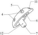
图1为本发明实施例1提供的尺骨冠状突假体装置的三维侧视图;1 is a three-dimensional side view of the ulna coronoid prosthesis device provided in
图2为本发明实施例1提供的尺骨冠状突假体的正面视图;2 is a front view of the ulna coronoid prosthesis provided in Example 1 of the present invention;
图3为本发明实施例1提供的尺骨冠状突假体的侧面视图;3 is a side view of the ulna coronoid prosthesis provided in Example 1 of the present invention;
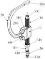
图4为本发明实施例2提供的尺骨冠状突假体安装器的正面三维视图;4 is a front three-dimensional view of the ulna coronoid prosthesis installer provided in
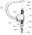
图5为本发明实施例2提供的尺骨冠状突假体安装器的侧面三维视图;5 is a side three-dimensional view of the ulna coronoid prosthesis installer provided in
图6为本发明实施例2提供的C型固定臂的三维视图;6 is a three-dimensional view of the C-shaped fixed arm provided in
图7为本发明实施例2提供的C型固定臂的连接头的三维视图;7 is a three-dimensional view of the connector of the C-shaped fixed arm provided in
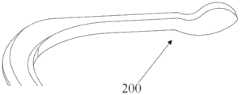
图8为本发明实施例2提供的C型固定臂的定位块的三维视图;8 is a three-dimensional view of the positioning block of the C-shaped fixed arm provided in
图9为本发明实施例3提供的尺骨冠状突假体装置的安装过程的示意图。FIG. 9 is a schematic diagram of the installation process of the ulna coronoid prosthesis device provided in
具体实施方式Detailed ways
实施例1Example 1
实施例1提供一种尺骨冠状突假体装置,下面对其结构进行详细描述。
参考图1至图3,该尺骨冠状突假体装置包括一个冠状突假体1、一个尺骨植入螺栓2和一个锁定螺钉3。Referring to FIGS. 1 to 3 , the ulna coronoid prosthesis device includes a
其中,该冠状突假体1包括蘑菇体11和定位柱12,蘑菇体11和定位柱12固定连接。优选地,定位柱12垂直固定于蘑菇体11底平面中部,定位柱12的底部内设置有螺钉孔7。其中,尺骨植入螺栓2由螺杆和螺栓头组成,其中螺杆上设置有螺纹。The
蘑菇体11的外表面由外曲面和底平面围成,其中底平面与尺骨关节面接触。为了方便固定和移动冠状突假体1,蘑菇体11的外曲面上设置有多个卡钳夹持孔4,该卡钳夹持孔4有利于卡钳夹持住后的固定和移动。优选地,蘑菇体11的外曲面上的卡钳夹持孔4的数量为双数个,且卡钳夹持孔4均匀分布于蘑菇体11的外曲面上,作为一种具体的实施方式,蘑菇体11的外曲面上的卡钳夹持孔4的数量为四个。The outer surface of the
蘑菇体11的侧向位贯穿设有一个斜向穿孔5,该斜向穿孔5贯通于蘑菇体11的外曲面和蘑菇体11的底平面。且该斜向穿孔5的中轴线与定位柱12的纵向中心线不共面。An oblique through
锁定螺钉3从蘑菇体11的外曲面上的斜向穿孔5穿入,且锁定螺钉3的螺钉头露出所述蘑菇体11的底平面,该露出的螺钉头用于固定连接尺骨模型8,以提高冠状突假体1的稳定性和抗旋转能力。The locking
蘑菇体11的底平面与尺骨截骨面接触处设置有仿骨小梁多孔结构界面层6,仿骨小梁多孔结构界面层6采用钛合金材质3D打印而成的仿骨小梁多孔结构,仿骨小梁多孔结构为多孔状平面,便于骨质后期生长长入至仿骨小梁多孔结构界面层6内,对假体形成长期固定。该技术为现有技术,详情请参阅中国发明专利《3D打印仿骨小梁多孔承重增强金属假体》(申请号为CN201610222225.0),其中仿骨小梁多孔结构界面层6的孔隙率为60~80%。A trabecular bone-like porous
需要说明的是,冠状突假体1能否有效克服摩擦磨损是手术实施是否成功的关键,即要求假体关节面,即蘑菇体11的外曲面,其抛光处理使表面粗糙度达到Ra0.1以下。为了减少关节面磨损及金属离子析出,增加冠状突假体1植入后的稳定性,需要在其表面上制备一层TiN涂层。这是在冠状突假体植入人体后经活动摩擦产生黑水以及微振磨损,会引起植入物的疲劳强度迅速降低,导致断裂,由于TC4材料耐磨性差,所以在该假体关节面制备一层TiN涂层,可提高假体的耐磨性和耐腐蚀性并同时改善金属离子释放性能。It should be noted that whether the
优选地,蘑菇体11和定位柱12采用钛合金材质3D打印而成,且蘑菇体11和定位柱12一体成型。Preferably, the
尺骨植入螺栓2与定位柱12的底部的螺钉孔7通过螺纹固定连接。The
实施例2Example 2
实施例2提供一种尺骨冠状突假体安装器,用于将实施例1的尺骨冠状突假体进行置换病患尺骨冠状突的手术,下面对其结构进行详细描述。
参考图4和图5,该尺骨冠状突假体安装器包括导向座10、C型固定臂20、螺纹套管30、定位柱钻孔套管40、克氏针套管50、定位柱通孔空心钻头和螺栓头孔空心钻钻头。其中,所述定位柱通孔空心钻头的最大外径等于所述定位柱12的外径,螺栓头孔空心钻钻头的最大外径等于尺骨植入螺栓2的外径。Referring to FIGS. 4 and 5 , the ulna coronoid prosthesis installer includes a
螺纹套管30的顶端和底端分别设置有固定头300和第一套筒310,其中固定头30的前端均匀设置有多个固定齿。The top and bottom ends of the threaded
导向座10内部开设有螺纹套管孔,该螺纹套管孔的内壁设有内螺纹,螺纹套管30的外管壁设有外螺纹,导向座10通过螺纹套管孔内套设螺纹套管30上,通过导向座10的螺纹套管孔与螺纹套管30的外螺纹的螺纹连接,实现螺纹套管30于导向座10上的高度可调。这种可利用该螺纹套管30的外螺纹与导向座10的螺纹套管孔的螺纹连接,通过螺纹旋入或旋出实现上下调节螺纹套管30在导向座10上的高度位置,从而实现定位块200与固定头300之间间距的调节方式称为高度粗调方式。The
作为具体的实施方式,第一套筒310上端可以通过螺纹连接等可拆卸连接的方式固定于所述螺纹套管30底端的外壁上,也可以通过焊接或一体成型等不可拆卸连接的方式与螺纹套管30底端固定连接。所述第一套筒310下端内壁设有内螺纹。As a specific embodiment, the upper end of the
所述定位柱钻孔套管40底端设置有第二套筒410,所述第二套筒410上端的外壁和下端的内壁分别设有外螺纹和内螺纹;所述克氏针套管50的底端设置有第三套筒510,所述第三套筒510上端的外壁设有外螺纹。A
所述定位柱钻孔套管40穿设于所述螺纹套管30内,所述克氏针套管50穿设于所述定位柱钻孔套管40。而且第二套筒410上端外壁的外螺纹与所述第一套筒310下端内壁的内螺纹通过螺纹连接,以实现所述定位柱钻孔套管40与所述螺纹套管30的底端的可拆卸连接锁紧;所述第三套筒510上端外壁的外螺纹与所述第二套筒410下端内壁的内螺纹通过螺纹连接,以实现克氏针套管50的底端与所述定位柱钻孔套管40的底端的可拆卸连接锁紧。The positioning
参考图4至图6,C型固定臂20的形状呈“C”形,其顶端设置有定位块200,其底端与所述导向座10的侧壁相连接。Referring to FIG. 4 to FIG. 6 , the shape of the C-shaped fixed
作为一种连接方式,C型固定臂20的底端可以与所述导向座10的侧壁直接固定连接,甚至一体成型。但是,为了不同患者的尺骨高低不同,为了增强该尺骨冠状突假体安装器应用的普适性,除了高度粗调方式以外,通过设置高度微调机构,使定位块200与固定头300之间间距存在另一种调节方式,另外这种调节方式称为高度微调方式。As a connection method, the bottom end of the C-shaped fixed
具体地,该高度微调机构包括连接头210、燕尾槽导轨1100和锁紧螺栓60。Specifically, the height fine adjustment mechanism includes a connecting
导向座10的侧壁的竖直方向设置有燕尾槽导轨1100,参考图7,C型固定臂20的底端设置有连接头210,所述连接头210的侧壁竖直方向设置有燕尾槽110,其中燕尾槽110的横截面为梯形,燕尾槽导轨1100又被称为梯形导轨,燕尾槽110和燕尾槽导轨1100相互配合使用,C型固定臂20通过燕尾槽110可滑动设置于所述导向座10的燕尾槽导轨1100上。连接头210通过燕尾槽110可在燕尾槽导轨1100上滑动,可限制了连接头210相对于导向座10的前后左右方向的位移,只允许连接头210相对于导向座10的上下方向的位移,起到竖直方向上导向作用。The vertical direction of the side wall of the
所述连接头210内设置有锁紧螺栓通孔600,所述锁紧螺栓通孔600的内壁设置有内螺纹,所述锁紧螺栓60设置于所述锁紧螺栓通孔600内并通过螺纹旋紧直至所述锁紧螺栓60的螺杆紧固抵触所述导向座10的侧壁,以锁紧连接头210竖直方向的位移。The connecting
需要说明的是,在导向座10于所述螺纹套管30上的高度不变时,可以通过燕尾槽110和燕尾槽导轨1100的相对滑动调节连接头210与导向座10的相对位置,最后通过锁紧螺栓60锁紧连接头210,以实现定位块200与固定头300间距的微调。这是因为燕尾槽110在燕尾槽导轨1100上发生相对滑动,可改变定位块200相对于导向座10的高度,直至高度满足要求时,由于燕尾槽110限制了连接头210相对于导向座10的前后左右方向的位移,使用锁紧螺栓60穿过锁紧螺栓通孔600并通过螺纹旋紧,继续限制连接头210相对于导向座10上下方向的位移,实现将连接头210竖直方向的锁紧,最终实现导向座10与C形固定臂1高度上的相对位置的调节。It should be noted that, when the height of the
定位块200的下表面紧贴尺骨的上表面,螺纹套管30的作用于尺骨的下表面,调节导向座10于螺纹套管30上的高度,实现对尺骨的上、下表面形成压缩式夹紧。观察患者尺骨关节面与定位块200相应点的匹配程度,根据该匹配程度对定位块200与固定头300间距进行微调,有助于增加手术容错率。此外,微调过程中,有助于使尺骨冠状突假体关节面与尺骨关节面的顺应程度满足要求,不给患者术后患处遗留疼痛。The lower surface of the
参考图8,所述定位块200的上表面与下表面均为平面,所述定位块200的两个侧面为弧面,所述定位块200侧面外形与冠状突假体1侧面外形一致,以保证所述定位块200在尺骨上留下的印痕适合容纳冠状突假体1的侧面。其中,所述定位块200的下表面与所述螺纹套管30的中轴线垂直,以使克氏针从克氏针套管50穿出时,能从截骨面垂直穿出,保证克氏针的笔直性。Referring to FIG. 8 , the upper surface and the lower surface of the
具体地,通过对绝大数人的尺骨进行尺寸统计后分析,一种满足尺骨冠状突假体置换病患的尺骨冠状突的手术的螺纹套管30、定位柱钻孔套管40、克氏针套管50的尺寸要求为:螺纹套管30的外径为12mm,外螺纹规格为公制螺纹M12,内径为8mm;定位柱钻孔套管40的外径为8mm,内径6mm;克氏针套管50的外径为6mm,内径为1.6mm;定位柱通孔空心钻头的最大外径为6mm,螺栓头孔的最大外径为8mm。Specifically, through the statistical analysis of the size of the ulna of the vast majority of people, a threaded
此外,该尺骨冠状突假体安装器还包括定位柱通孔空心钻头和螺栓头孔空心钻钻头,当需要钻定位柱通孔时,所述定位柱通孔空心钻头置于所述定位柱钻孔套管4内;当需要螺栓头孔时,所述螺栓头孔空心钻钻头置于所述螺纹套管3内。In addition, the ulna coronoid prosthesis installer also includes a positioning column through-hole hollow drill bit and a bolt head hole hollow drill bit. When the positioning column through-hole needs to be drilled, the positioning column through-hole hollow drill bit is placed on the positioning column drill. When the bolt head hole is required, the hollow drill bit of the bolt head hole is placed in the threaded
其中,定位块200与固定头300之间的间距用于放置尺骨模型8;Wherein, the distance between the
螺纹套管30的内径与尺骨植入螺栓2的外径相等,用于置入定位柱通孔空心钻头,钻出安装尺骨植入螺栓2的安装孔;The inner diameter of the threaded
定位柱钻孔套管40的内径与冠状突假体1的定位柱12外径相等,用于置入螺栓头孔空心钻钻头,从下至上钻穿尺骨得到定位柱通孔,该定位柱通孔的上部用于作为定位柱12的安装孔;The inner diameter of the positioning
克氏针套管50用于穿设克氏针,主要是起到导向,保证螺纹套管30、定位柱钻孔套管40所钻出的安装孔的笔直性。The
实施例3Example 3
实施例3提供一种尺骨冠状突假体装置的安装方法,使用实施例2提供的尺骨冠状突假体安装器,以中国发明专利《一种骨科用模拟演示模型》(申请号为CN201821079192.X)中涉及的尺骨模型为实验对象,其中尺骨模型8通过连接绳组件于桡骨模型捆绑连接,拆卸方便,将实施例1提供的尺骨冠状突假体装置安装于尺骨模型8上,旨在为医生提供训练操作机会以提升医生尺骨冠状突假体置换手术的操作水平,参考图9所示,该安装方法包括以下步骤:
步骤A:使用尺骨冠状突假体安装器在尺骨模型8的下表面向上贯穿钻出定位柱通孔,所述定位柱通孔分别在所述尺骨模型8的上表面露出顶部孔和下表面露出底部孔;继续使用尺骨冠状突假体安装器在尺骨模型8的下表面钻出用于嵌入尺骨植入螺栓的螺栓头的螺栓头孔;且所述定位柱通孔的上部用于安装冠状突假体1的定位柱12,所述定位柱通孔的下部用于安装尺骨植入螺栓;Step A: Use the ulna coronoid prosthesis installer to drill positioning post through holes upward through the lower surface of the
步骤B:设置冠状突假体1:利用卡钳夹持任意两个卡钳夹持孔4移动冠状突假体1,将冠状突假体1的定位柱12从尺骨模型8的顶部孔置入至定位柱通孔;Step B: Setting the coronoid prosthesis 1: Use calipers to clamp any two
设置尺骨植入螺栓2:将尺骨植入螺栓2从尺骨模型8的底部孔置入至定位柱通孔,直至尺骨植入螺栓2穿过尺骨模型8与定位柱12相抵触,且尺骨植入螺栓2的螺栓头接近尺骨模型8的底部孔;Set the ulna implant bolt 2: Insert the
连接冠状突假体1和尺骨植入螺栓2:利用卡钳夹夹持两个卡钳夹持孔4以固定冠状突假体1,旋紧尺骨植入螺栓2的螺栓头,直至尺骨植入螺栓2和定位柱12螺纹固定连接,且尺骨植入螺栓2螺栓头正好嵌入尺骨模型8的底部孔周围;Connect the
继续加固冠状突假体1与尺骨模型8的连接:将锁定螺钉3从蘑菇体11的外曲面的斜向穿孔5穿入,并旋紧该锁定螺钉3,直至锁定螺钉3的螺钉头固定于尺骨模型8内。Continue to reinforce the connection between the
其中,所述步骤A包括以下步骤:Wherein, the step A includes the following steps:
步骤S1:手术前,对病患的尺骨关节面进行预处理,截取原有的尺骨冠状突形成截骨面,其中截骨面为平面,根据冠状突假体1侧面外形制作定位块200,根据截骨面的位置以及尺骨关节面和定位块200对应点的顺应程度确定冠状突假体1的安装位置;Step S1: Before the operation, pre-process the articular surface of the patient's ulna, cut the original coronoid process of the ulna to form an osteotomy surface, wherein the osteotomy surface is a plane, and make a
步骤S2:将定位块200下表面紧贴尺骨模型8的上表面,通过旋转螺纹套管30实现螺纹套管30在导向座10上高度位置的调节,直至螺纹套管30的固定头300靠近尺骨模型8的下表面;Step S2: Press the lower surface of the
步骤S3:先后依次定位柱钻孔套管40旋入所述螺纹套管30内、克氏针套管50旋入所述定位柱钻孔套管40,第二套筒410与第一套筒310通过螺纹连接锁紧,第三套筒510与第二套筒410通过螺纹连接锁紧;Step S3: the positioning
步骤S4:将外径1.6mm克氏针穿入克氏针套管50内,直至克氏针穿出截骨面,保留克氏针,退出克氏针套管50;Step S4: Insert the 1.6mm outer diameter K-wire into the K-
步骤S5:利用定位柱钻孔套管40的固定头对尺骨模型8的下表面进行钻孔,直至定位柱钻孔套管40钻入至尺骨模型8高度的一半,退出定位柱钻孔套管40;Step S5: Use the fixed head of the positioning
步骤S6:螺栓头孔空心钻钻头接上钻杆,将螺栓头孔空心钻钻头置于所述螺纹套管30内,利用螺栓头孔空心钻钻头对尺骨8的下表面进行钻孔,直至螺栓头孔空心钻钻头钻出螺栓头孔,该螺栓头孔的深度与与尺骨植入螺栓2的螺栓头的后度相等;Step S6: the bolt head hole hollow drill bit is connected to the drill rod, the bolt head hole hollow drill bit is placed in the threaded
步骤S7:定位柱通孔空心钻头接上钻杆,将定位柱通孔空心钻头置于所述定位柱钻孔套管40内,利用定位柱通孔空心钻头对尺骨模型8的下表面进行钻孔,直至从下至上完全打穿尺骨模型8得到定位柱通孔,该定位柱通孔的孔径与定位柱12、尺骨植入螺栓2的外径相等;Step S7: the positioning column through-hole hollow drill bit is connected to the drill rod, the positioning column through-hole hollow drill bit is placed in the positioning
步骤S8:从上往下一起退出定位柱钻孔套管40和克氏针;Step S8: withdraw the positioning
步骤S9:旋动螺纹套管30,直至螺纹套管30离开导向座10的下表面。Step S9 : Rotate the threaded
优选地,在步骤S3和步骤S4之间,增加以下步骤:Preferably, between step S3 and step S4, the following steps are added:
观察患者截骨处尺骨关节面与定位块200相应点的匹配程度,根据该匹配程度对定位块200与固定头300间距进行微调,Observe the degree of matching between the articular surface of the ulna at the osteotomy site and the corresponding point of the
在燕尾槽导轨1100上滑动连接头210,进行定位块200与固定头300间距的微调,直至螺纹套管30的固定头300垂直抵触尺骨模型8的下表面;Slide the connecting
将锁紧螺栓60设置于所述锁紧螺栓通孔600内并通过螺纹旋紧直至所述锁紧螺栓60的螺杆紧固抵触所述导向座10的侧壁,以锁紧连接头210竖直方向的位移。Set the locking
虽然,上文中已经用一般性说明及具体实施例对本发明作了详尽的描述,但在本发明基础上,可以对之作一些修改或改进,这对本领域技术人员而言是显而易见的。因此,在不偏离本发明精神的基础上所做的这些修改或改进,均属于本发明要求保护的范围。Although the present invention has been described in detail above with general description and specific embodiments, some modifications or improvements can be made on the basis of the present invention, which will be obvious to those skilled in the art. Therefore, these modifications or improvements made without departing from the spirit of the present invention fall within the scope of the claimed protection of the present invention.
Claims (10)
Translated fromChinesePriority Applications (1)
| Application Number | Priority Date | Filing Date | Title |
|---|---|---|---|
| CN202010509468.9ACN111938874B (en) | 2020-06-04 | 2020-06-04 | A kind of ulnar coronoid prosthesis device and its installer and installation method |
Applications Claiming Priority (1)
| Application Number | Priority Date | Filing Date | Title |
|---|---|---|---|
| CN202010509468.9ACN111938874B (en) | 2020-06-04 | 2020-06-04 | A kind of ulnar coronoid prosthesis device and its installer and installation method |
Publications (2)
| Publication Number | Publication Date |
|---|---|
| CN111938874Atrue CN111938874A (en) | 2020-11-17 |
| CN111938874B CN111938874B (en) | 2023-06-09 |
Family
ID=73337006
Family Applications (1)
| Application Number | Title | Priority Date | Filing Date |
|---|---|---|---|
| CN202010509468.9AActiveCN111938874B (en) | 2020-06-04 | 2020-06-04 | A kind of ulnar coronoid prosthesis device and its installer and installation method |
Country Status (1)
| Country | Link |
|---|---|
| CN (1) | CN111938874B (en) |
Cited By (1)
| Publication number | Priority date | Publication date | Assignee | Title |
|---|---|---|---|---|
| CN113827377A (en)* | 2021-09-24 | 2021-12-24 | 北京积水潭医院 | Joint prosthesis for assisting forearm rotation |
Citations (8)
| Publication number | Priority date | Publication date | Assignee | Title |
|---|---|---|---|---|
| US20050049710A1 (en)* | 2003-08-28 | 2005-03-03 | O'driscoll Shawn W. | Prosthesis for partial replacement of an articulating surface on bone |
| EP1550418A1 (en)* | 2003-12-30 | 2005-07-06 | Zimmer Technology, Inc. | Implant systems with fastener for mounting on an articulation surface of an orthopedic joint |
| CN201168071Y (en)* | 2008-03-13 | 2008-12-24 | 王友华 | Ulna coronal process prosthesis |
| CN103479450A (en)* | 2013-10-16 | 2014-01-01 | 中国人民解放军总医院 | Condyle prosthesis and manufacturing method thereof |
| CN204158482U (en)* | 2014-09-26 | 2015-02-18 | 北京积水潭医院 | A kind of for coronoid process fracture locating guider under surgery elbow arthroscopy |
| CN106137465A (en)* | 2016-07-21 | 2016-11-23 | 北京爱康宜诚医疗器材有限公司 | Borrowed structure |
| CN206630736U (en)* | 2016-08-29 | 2017-11-14 | 宁波市北仑区人民医院 | A kind of ulna coronal process prosthesis |
| CN110368140A (en)* | 2019-08-05 | 2019-10-25 | 北京爱康宜诚医疗器材有限公司 | Femoral implant |
- 2020
- 2020-06-04CNCN202010509468.9Apatent/CN111938874B/enactiveActive
Patent Citations (8)
| Publication number | Priority date | Publication date | Assignee | Title |
|---|---|---|---|---|
| US20050049710A1 (en)* | 2003-08-28 | 2005-03-03 | O'driscoll Shawn W. | Prosthesis for partial replacement of an articulating surface on bone |
| EP1550418A1 (en)* | 2003-12-30 | 2005-07-06 | Zimmer Technology, Inc. | Implant systems with fastener for mounting on an articulation surface of an orthopedic joint |
| CN201168071Y (en)* | 2008-03-13 | 2008-12-24 | 王友华 | Ulna coronal process prosthesis |
| CN103479450A (en)* | 2013-10-16 | 2014-01-01 | 中国人民解放军总医院 | Condyle prosthesis and manufacturing method thereof |
| CN204158482U (en)* | 2014-09-26 | 2015-02-18 | 北京积水潭医院 | A kind of for coronoid process fracture locating guider under surgery elbow arthroscopy |
| CN106137465A (en)* | 2016-07-21 | 2016-11-23 | 北京爱康宜诚医疗器材有限公司 | Borrowed structure |
| CN206630736U (en)* | 2016-08-29 | 2017-11-14 | 宁波市北仑区人民医院 | A kind of ulna coronal process prosthesis |
| CN110368140A (en)* | 2019-08-05 | 2019-10-25 | 北京爱康宜诚医疗器材有限公司 | Femoral implant |
Cited By (2)
| Publication number | Priority date | Publication date | Assignee | Title |
|---|---|---|---|---|
| CN113827377A (en)* | 2021-09-24 | 2021-12-24 | 北京积水潭医院 | Joint prosthesis for assisting forearm rotation |
| CN113827377B (en)* | 2021-09-24 | 2023-06-16 | 北京积水潭医院 | Joint prosthesis to assist forearm rotation |
Also Published As
| Publication number | Publication date |
|---|---|
| CN111938874B (en) | 2023-06-09 |
Similar Documents
| Publication | Publication Date | Title |
|---|---|---|
| US5556278A (en) | Method for making and using a template for a dental implant osteotomy and components relating thereto | |
| RU2339336C2 (en) | Method for manufacturing of dental prosthesis in full or partial toothlessness | |
| CN106175997B (en) | A kind of artificial dentata supporter | |
| CN105852931A (en) | Additive-manufactured guiding positioning assembly for jawbone tumor resection and reconstruction | |
| RU177272U1 (en) | Implant placement surgical template | |
| CN203042413U (en) | Universal locking and pressurizing bone plate | |
| CN106137409B (en) | A kind of positioning auxiliary device and its application method for fracture of neck of femur | |
| MXPA03002736A (en) | Maxillary distractor. | |
| CN111938874B (en) | A kind of ulnar coronoid prosthesis device and its installer and installation method | |
| CN112603514A (en) | Plum blossom direction steel sheet for femoral neck fracture | |
| CN104873256A (en) | Splicing device for pulling close fibulas on two sides after fibula section cutting osteotomy | |
| CN210749450U (en) | Spinal full cortical bone screw and spinal positioning and orientation device | |
| CN219207253U (en) | Percutaneous guide plate for pelvic fracture | |
| CN116898527B (en) | A drilling guide device for temporomandibular joint disc reduction and anchorage surgery | |
| CN204765868U (en) | Stress dissipation type locking pressurizing coaptation board | |
| CN220404069U (en) | Combined mandibular angle and chin operation osteotomy positioning guide plate for intraoral approach | |
| DE10033918B4 (en) | Device / implant for guided distraction osteogenesis in atrophied alveolar jawbone | |
| CN216495582U (en) | 3D printing guidance biological type titanium alloy sacral nail-plate internal fixation device for spine | |
| CN101953712B (en) | Semi-self-locking acetabulum posterior wall and posterior column anatomical plate | |
| RU2766250C1 (en) | Implant for replacing the area of a bone defect on the anterior surface of the glenoid of the shoulder blade and a manipulator for its installation | |
| CN216455179U (en) | Positioner is used in operation of microfracture | |
| CN109758209B (en) | Loose-leaf nail, shaft nail and biplane osteotomy guiding device | |
| CN111658067B (en) | Skull drilling and positioning device | |
| CN204708955U (en) | Further after a kind of fibula section cuts osteotomy the plug assembly of both sides fibula | |
| CN111557766A (en) | A 3D printed titanium alloy ulna coronoid prosthesis device |
Legal Events
| Date | Code | Title | Description |
|---|---|---|---|
| PB01 | Publication | ||
| PB01 | Publication | ||
| SE01 | Entry into force of request for substantive examination | ||
| SE01 | Entry into force of request for substantive examination | ||
| GR01 | Patent grant | ||
| GR01 | Patent grant |