CN111938870A - Valve clamping device with locking mechanism and valve repair system - Google Patents
Valve clamping device with locking mechanism and valve repair systemDownload PDFInfo
- Publication number
- CN111938870A CN111938870ACN202010855704.2ACN202010855704ACN111938870ACN 111938870 ACN111938870 ACN 111938870ACN 202010855704 ACN202010855704 ACN 202010855704ACN 111938870 ACN111938870 ACN 111938870A
- Authority
- CN
- China
- Prior art keywords
- locking
- clamping device
- valve
- locking mechanism
- fixed base
- Prior art date
- Legal status (The legal status is an assumption and is not a legal conclusion. Google has not performed a legal analysis and makes no representation as to the accuracy of the status listed.)
- Granted
Links
Images


Classifications
- A—HUMAN NECESSITIES
- A61—MEDICAL OR VETERINARY SCIENCE; HYGIENE
- A61F—FILTERS IMPLANTABLE INTO BLOOD VESSELS; PROSTHESES; DEVICES PROVIDING PATENCY TO, OR PREVENTING COLLAPSING OF, TUBULAR STRUCTURES OF THE BODY, e.g. STENTS; ORTHOPAEDIC, NURSING OR CONTRACEPTIVE DEVICES; FOMENTATION; TREATMENT OR PROTECTION OF EYES OR EARS; BANDAGES, DRESSINGS OR ABSORBENT PADS; FIRST-AID KITS
- A61F2/00—Filters implantable into blood vessels; Prostheses, i.e. artificial substitutes or replacements for parts of the body; Appliances for connecting them with the body; Devices providing patency to, or preventing collapsing of, tubular structures of the body, e.g. stents
- A61F2/02—Prostheses implantable into the body
- A61F2/24—Heart valves ; Vascular valves, e.g. venous valves; Heart implants, e.g. passive devices for improving the function of the native valve or the heart muscle; Transmyocardial revascularisation [TMR] devices; Valves implantable in the body
- A61F2/2442—Annuloplasty rings or inserts for correcting the valve shape; Implants for improving the function of a native heart valve
- A61F2/246—Devices for obstructing a leak through a native valve in a closed condition
- A—HUMAN NECESSITIES
- A61—MEDICAL OR VETERINARY SCIENCE; HYGIENE
- A61F—FILTERS IMPLANTABLE INTO BLOOD VESSELS; PROSTHESES; DEVICES PROVIDING PATENCY TO, OR PREVENTING COLLAPSING OF, TUBULAR STRUCTURES OF THE BODY, e.g. STENTS; ORTHOPAEDIC, NURSING OR CONTRACEPTIVE DEVICES; FOMENTATION; TREATMENT OR PROTECTION OF EYES OR EARS; BANDAGES, DRESSINGS OR ABSORBENT PADS; FIRST-AID KITS
- A61F2/00—Filters implantable into blood vessels; Prostheses, i.e. artificial substitutes or replacements for parts of the body; Appliances for connecting them with the body; Devices providing patency to, or preventing collapsing of, tubular structures of the body, e.g. stents
- A61F2/02—Prostheses implantable into the body
- A61F2/24—Heart valves ; Vascular valves, e.g. venous valves; Heart implants, e.g. passive devices for improving the function of the native valve or the heart muscle; Transmyocardial revascularisation [TMR] devices; Valves implantable in the body
- A61F2/2442—Annuloplasty rings or inserts for correcting the valve shape; Implants for improving the function of a native heart valve
- A61F2/2466—Delivery devices therefor
Landscapes
- Health & Medical Sciences (AREA)
- Cardiology (AREA)
- Oral & Maxillofacial Surgery (AREA)
- Transplantation (AREA)
- Engineering & Computer Science (AREA)
- Biomedical Technology (AREA)
- Heart & Thoracic Surgery (AREA)
- Vascular Medicine (AREA)
- Life Sciences & Earth Sciences (AREA)
- Animal Behavior & Ethology (AREA)
- General Health & Medical Sciences (AREA)
- Public Health (AREA)
- Veterinary Medicine (AREA)
- Surgical Instruments (AREA)
- Prostheses (AREA)
Abstract
Description
Translated fromChinese技术领域technical field
本发明涉及介入类医疗器械领域,尤其涉及一种带锁定机构的瓣膜夹合装置及瓣膜修复系统。The invention relates to the field of interventional medical devices, in particular to a valve clamping device with a locking mechanism and a valve repair system.
背景技术Background technique
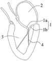
请参阅图1,二尖瓣1是位于心脏左心房2与左心室3之间的单向阀,正常健康的二尖瓣1可以控制血液从左心房2流到左心室3,同时避免血液从左心室3流到左心房2。二尖瓣1包括一对瓣叶,称为前叶1a及后叶1b。前叶1a及后叶1b通过腱索4固定于左心室3的乳头肌上。正常情况下,心脏收缩时,前叶1a和后叶1b的边缘完全对合,避免血液从左心室3流到左心房2。请参阅图2,当二尖瓣1的瓣叶或其相关结构发生器质性改变或功能性改变时,如腱索4部分断裂,二尖瓣1的前叶1a和后叶1b对合不良,由此,当心脏收缩时,二尖瓣1不能完全关闭,导致血液从左心室3返流至左心房2,从而引起一系列的病理生理改变,称为“二尖瓣返流”。Please refer to Figure 1, the
外科通常采用瓣膜缘对缘缝合术等手术方式治疗二尖瓣返流。但是这类外科手术存在手术过程复杂、手术成本高、病人创伤程度高、并发症风险高、住院时间长以及患者恢复过程痛苦等缺陷。现有一种微创治疗器械,其基于瓣膜的缘对缘手术原理,将瓣膜夹合器通过介入导管输送至二尖瓣处,再通过夹合器的相对开合同时抓持二尖瓣的前叶和后叶,从而将瓣叶拉向彼此,达到减小瓣叶间隙、治疗二尖瓣返流的目的。Surgical procedures such as edge-to-edge suturing are usually used to treat mitral regurgitation. However, this type of surgery has disadvantages such as complex surgical procedure, high surgical cost, high degree of patient trauma, high risk of complications, long hospital stay, and painful recovery process for patients. There is a minimally invasive treatment device, which is based on the principle of edge-to-edge operation of the valve, and delivers a valve clamp to the mitral valve through an interventional catheter, and then simultaneously grasps the front of the mitral valve through the relative opening of the clamp. The leaflets and the posterior leaflets, thereby pulling the leaflets toward each other, achieve the purpose of reducing the leaflet gap and treating mitral regurgitation.
现有一种带锁定机构的瓣膜夹,锁定机构包括一个楔形元件和与楔形元件搭接的金属框架,楔形元件的中间设有一个通孔,通孔中穿设瓣膜夹合器的驱动轴,当向近端拉动金属框架时,楔形元件的一端被拉动,另一端不动,从而减小驱动轴与通孔之间的摩擦,使得驱动轴可以在通孔中移动。然而,由于驱动轴表面为光滑结构,楔形元件的通孔内表面也是光滑结构,二者之间的摩擦力较小,因此锁定力较小,锁定机构可能会出现磨损滑移或失效,导致在输送过程中瓣膜夹合器提前打开、或者在夹持瓣叶过程中意外打开、或者在植入后发生瓣膜夹脱落,导致手术失败甚至严重危害患者生命健康。There is a valve clamp with a locking mechanism. The locking mechanism includes a wedge-shaped element and a metal frame that overlaps with the wedge-shaped element. When the metal frame is pulled proximally, one end of the wedge-shaped element is pulled and the other end is stationary, thereby reducing the friction between the drive shaft and the through hole, so that the drive shaft can move in the through hole. However, since the surface of the drive shaft is a smooth structure, and the inner surface of the through hole of the wedge-shaped element is also a smooth structure, the friction force between the two is small, so the locking force is small, and the locking mechanism may wear, slip or fail, resulting in During the delivery process, the valve clamp is opened in advance, or accidentally opened during the process of clamping the valve leaflets, or the valve clamp falls off after implantation, resulting in failure of the operation and even serious harm to the life and health of the patient.
发明内容SUMMARY OF THE INVENTION
有鉴于此,本发明提供一种带锁定机构的瓣膜夹合装置,能提高锁定机构的锁紧力,防止锁定失效,提高瓣膜夹合装置的安全性及抗疲劳性能。In view of this, the present invention provides a valve clamping device with a locking mechanism, which can improve the locking force of the locking mechanism, prevent locking failure, and improve the safety and fatigue resistance of the valve clamping device.
为解决上述技术问题,本发明提供一种带锁定机构的瓣膜夹合装置,包括固定基座、至少一对钳臂、驱动组件,以及锁定机构,所述至少一对钳臂与所述固定基座连接并可相对所述固定基座开合;所述驱动组件包括活动地插设于所述固定基座中的驱动轴,所述驱动轴沿轴向移动以带动所述钳臂相对于所述固定基座开合,所述驱动轴的外周面设有定位部;所述锁定机构包括锁定件及抵推件,所述锁定件沿轴向开设锁定孔,所述驱动轴穿插于所述锁定孔中,所述抵推件抵顶所述锁定件倾斜设置于所述固定基座中,使得所述锁定孔的边缘卡接于所述定位部。In order to solve the above-mentioned technical problems, the present invention provides a valve clamping device with a locking mechanism, comprising a fixed base, at least a pair of clamp arms, a drive assembly, and a locking mechanism, the at least one pair of clamp arms and the fixed base. The base is connected and can be opened and closed relative to the fixed base; the drive assembly includes a drive shaft movably inserted in the fixed base, and the drive shaft moves in the axial direction to drive the clamp arm relative to the fixed base. The fixed base is opened and closed, and the outer peripheral surface of the drive shaft is provided with a positioning portion; the locking mechanism includes a locking piece and a pushing piece, the locking piece is provided with a locking hole along the axial direction, and the drive shaft is inserted through the In the locking hole, the pushing member is inclined against the locking member and is disposed in the fixing base, so that the edge of the locking hole is clamped to the positioning portion.
本发明还提供一种瓣膜修复系统,包括瓣膜夹合装置以及与所述瓣膜夹合装置可拆卸连接的输送装置,所述输送装置包括操作丝,所述操作丝的远端与所述解锁控制件之间可拆卸连接。The present invention also provides a valve repair system, comprising a valve clamping device and a delivery device detachably connected to the valve clamping device, the delivery device comprising an operation wire, the distal end of the operation wire is connected to the unlocking control device Detachable connection between parts.
本发明提供的瓣膜夹合装置的驱动轴外周面设有定位部,驱动轴穿插于锁定件中,抵推件抵顶锁定件倾斜设置于固定基座中,使得锁定孔的边缘卡接于定位部,来增加驱动轴与锁定件的摩擦力和机械咬合力,不仅可以防止锁定件的锁定孔边缘局部受力而发生磨损,并且驱动轴与锁定孔的边缘具有一定的咬合量,在受力作用下两者会更紧咬合,驱动轴与锁定孔的边缘之间不是单纯靠摩擦力来配合,提高了锁定机构的锁定力及稳定性,防止瓣膜夹合装置出现锁定失效的情况。The outer peripheral surface of the drive shaft of the valve clamping device provided by the present invention is provided with a positioning portion, the drive shaft is inserted into the locking member, and the abutting member abuts the locking member and is obliquely arranged in the fixed base, so that the edge of the locking hole is clamped in the positioning It can not only prevent the edge of the locking hole of the locking piece from being partially stressed and wear out, but also the edge of the driving shaft and the locking hole have a certain amount of bite, and the edge of the locking hole has a certain amount of engagement. Under the action, the two will be more tightly engaged, and the driving shaft and the edge of the locking hole are not matched by frictional force alone, which improves the locking force and stability of the locking mechanism and prevents the valve clamping device from locking failure.
附图说明Description of drawings
为了更清楚地说明本发明实施例的技术方案,下面将对实施方式中所需要使用的附图作简单地介绍,显而易见地,下面描述中的附图是本发明一些实施方式,对于本领域普通技术人员来讲,在不付出创造性劳动的前提下,还可以根据这些附图获得其它的附图。In order to illustrate the technical solutions of the embodiments of the present invention more clearly, the following briefly introduces the accompanying drawings used in the implementation manner. As far as technical personnel are concerned, other drawings can also be obtained based on these drawings without any creative effort.
图1是二尖瓣正常状态时的示意图。Figure 1 is a schematic view of the mitral valve in a normal state.
图2是二尖瓣出现病变时的示意图。Fig. 2 is a schematic diagram of the mitral valve with lesions.
图3是本发明的第一实施例提供的带锁定机构的瓣膜夹合装置的立体结构示意图。3 is a schematic three-dimensional structural diagram of a valve clamping device with a locking mechanism provided by the first embodiment of the present invention.
图4是图3中的带锁定机构的瓣膜夹合装置的侧视图。FIG. 4 is a side view of the valve clamping device with locking mechanism of FIG. 3 .
图5是图3中的瓣膜夹合装置的固定基座、部分驱动组件及锁定机构的立体结构示意图。FIG. 5 is a schematic three-dimensional structural diagram of the fixed base, part of the driving components and the locking mechanism of the valve clamping device in FIG. 3 .
图6是图5中的瓣膜夹合装置的固定基座、部分驱动组件及锁定机构的侧视图。FIG. 6 is a side view of the fixed base, part of the drive assembly and the locking mechanism of the valve clamping device of FIG. 5 .
图7是图6中VII部分的放大图。FIG. 7 is an enlarged view of part VII in FIG. 6 .
图8图5中省略抵推件及解锁控制件后的剖视图。FIG. 8 and FIG. 5 are cross-sectional views of the pushing member and the unlocking control member being omitted.
图9是图8中IX部分的放大图。FIG. 9 is an enlarged view of part IX in FIG. 8 .
图10是图3中的瓣膜夹合装置的驱动轴及连接座的立体结构示意图。FIG. 10 is a schematic three-dimensional structural diagram of the drive shaft and the connecting seat of the valve clamping device in FIG. 3 .
图11是图5中的锁定件的立体结构示意图。FIG. 11 is a schematic three-dimensional structural diagram of the locking member in FIG. 5 .
图12是图5中的抵推件的立体结构示意图。FIG. 12 is a schematic three-dimensional structural diagram of the pushing member in FIG. 5 .
图13是图12中的抵推件的另一实施方式的立体结构示意图。FIG. 13 is a schematic three-dimensional structural diagram of another embodiment of the pushing member in FIG. 12 .
图14是图5中的瓣膜夹合装置的锁定机构的解锁状态的立体结构示意图。FIG. 14 is a perspective structural schematic diagram of the unlocking state of the locking mechanism of the valve clamping device in FIG. 5 .
图15是图14中的瓣膜夹合装置的锁定机构的解锁状态的侧视图。FIG. 15 is a side view of the unlocked state of the locking mechanism of the valve clamping device of FIG. 14 .
图16是图15中XVI部分的放大图。FIG. 16 is an enlarged view of part XVI in FIG. 15 .
图17是图5中的解锁控制件的立体结构示意图。FIG. 17 is a schematic three-dimensional structural diagram of the unlocking control member in FIG. 5 .
图18是图17的解锁控制件的侧视图。FIG. 18 is a side view of the unlock control of FIG. 17 .
图19是图5中的固定基座、部分驱动组件及锁定机构与夹持臂的立体结构示意图。FIG. 19 is a schematic three-dimensional structural diagram of the fixing base, part of the driving assembly, the locking mechanism and the clamping arm in FIG. 5 .
图20是图19的侧视图。FIG. 20 is a side view of FIG. 19 .
图21是图3中的带锁定机构的瓣膜夹合装置的其中一使用状态示意图。FIG. 21 is a schematic diagram of one of the usage states of the valve clamping device with locking mechanism in FIG. 3 .
图22是图3中的带锁定机构的瓣膜夹合装置的闭合状态示意图。FIG. 22 is a schematic diagram of the closed state of the valve clamping device with a locking mechanism in FIG. 3 .
图23是本发明的第二实施例提供的带锁定机构的瓣膜夹合装置的立体结构示意图。23 is a schematic three-dimensional structural diagram of a valve clamping device with a locking mechanism provided by the second embodiment of the present invention.
图24是图23中的带锁定机构的瓣膜夹合装置的侧视图。FIG. 24 is a side view of the valve clamping device with locking mechanism of FIG. 23 .
图25是图23中的带锁定机构的瓣膜夹合装置的固定基座、部分驱动组件及锁定机构的结构示意图。FIG. 25 is a schematic structural diagram of the fixed base, part of the driving components and the locking mechanism of the valve clamping device with locking mechanism in FIG. 23 .
图26是图25中的瓣膜夹合装置的部分剖视图。FIG. 26 is a partial cross-sectional view of the valve clamping device of FIG. 25 .
图27是图26中的XXVII部分的放大图。FIG. 27 is an enlarged view of part XXVII in FIG. 26 .
图28是本发明的第三实施例提供的带锁定机构的瓣膜夹合装置的结构示意图。28 is a schematic structural diagram of a valve clamping device with a locking mechanism provided by a third embodiment of the present invention.
图29是本发明的第四实施例提供的带锁定机构的瓣膜夹合装置的结构示意图。FIG. 29 is a schematic structural diagram of a valve clamping device with a locking mechanism provided by a fourth embodiment of the present invention.
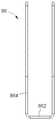
图30是本发明瓣膜夹合装置进行性能测试的结果统计图表。Fig. 30 is a statistical chart of the results of the performance test of the valve clamping device of the present invention.
具体实施方式Detailed ways
下面将结合本发明实施例中的附图,对本发明实施例中的技术方案进行清楚、完整地描述,显然,所描述的实施例仅仅是本发明的一部分实施例,而不是全部的实施例。基于本发明中的实施例,本领域普通技术人员在没有付出创造性劳动前提下所获得的所有其它实施例,都属于本发明保护的范围。The technical solutions in the embodiments of the present invention will be clearly and completely described below with reference to the accompanying drawings in the embodiments of the present invention. Obviously, the described embodiments are only a part of the embodiments of the present invention, not all of the embodiments. Based on the embodiments of the present invention, all other embodiments obtained by those of ordinary skill in the art without creative efforts shall fall within the protection scope of the present invention.
此外,以下各实施例的说明是参考附加的图示,用以例示本发明可用以实施的特定实施例。本发明中所提到的方向用语,例如,“上”、“下”、“前”、“后”、“左”、“右”、“内”、“外”、“侧面”等,仅是参考附加图式的方向,因此,使用的方向用语是为了更好、更清楚地说明及理解本发明,而不是指示或暗指所指的装置或元件必须具有特定的方位、以特定的方位构造和操作,因此不能理解为对本发明的限制。Furthermore, the following descriptions of the various embodiments refer to the accompanying drawings to illustrate specific embodiments in which the invention may be practiced. Directional terms mentioned in the present invention, such as "up", "down", "front", "rear", "left", "right", "inside", "outside", "side", etc., only Reference is made to the directions of the accompanying drawings, therefore, the directional terms used are for better and clearer description and understanding of the present invention, rather than indicating or implying that the device or element referred to must have a specific orientation, in a specific orientation construction and operation, and therefore should not be construed as limiting the invention.
在本发明的描述中,需要说明的是,在介入医疗器械领域,近端是指距离操作者较近的一端,而远端是指距离操作者较远的一端;轴向是指平行于自然状态下的医疗器械远端中心和近端中心连线的方向。上述定义只是为了表述方便,并不能理解为对本发明的限制。In the description of the present invention, it should be noted that in the field of interventional medical devices, the proximal end refers to the end closer to the operator, while the distal end refers to the end farther away from the operator; the axial direction refers to the end parallel to the natural The direction of the line connecting the center of the distal end and the center of the proximal end of the medical device in the state. The above definitions are only for the convenience of expression, and should not be construed as limiting the present invention.
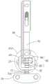
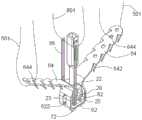
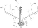
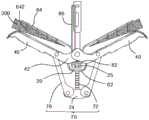
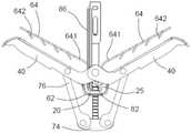
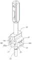
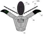
请一并参阅图3-图9,本发明的第一实施例提供一种瓣膜修复系统,其包括带锁定机构的瓣膜夹合装置100及与瓣膜夹合装置100可拆卸连接的输送装置500。瓣膜夹合装置100包括固定基座20、与固定基座20铰接的至少一对钳臂40、设于固定基座20和钳臂40之间的组织夹持件60、用于驱动钳臂40相对固定基座20开合的驱动组件70,以及设置于固定基座20的锁定机构80。至少一对钳臂40相对于固定基座20开合。组织夹持件60包括至少一对夹持臂64,每一夹持臂64被释放后向钳臂40靠拢并与对应一侧的钳臂40配合以夹持位于二者之间的瓣膜组织。Please refer to FIGS. 3 to 9 together. The first embodiment of the present invention provides a valve repair system, which includes a
具体地,驱动组件70包括活动地插设于固定基座20中的驱动轴72,驱动轴72沿轴向移动以带动钳臂40相对于固定基座20开合,驱动轴72的外周面设有定位部720。锁定机构80包括锁定件82及抵推件84,锁定件82沿轴向开设锁定孔820,驱动轴72穿插于锁定孔820中,抵推件84抵顶锁定件82倾斜设置于固定基座20中,使得锁定孔820的边缘281卡接于定位部720,以使驱动轴72与固定基座20相对固定,从而限制钳臂40与固定基座20之间的相对开合。Specifically, the
输送装置500包括管体组件、穿设在管体组件中的操作丝501及控制丝801,操作丝501连接夹持臂64,控制丝801连接锁定机构80,操作丝501及控制丝801分别延伸至患者体外。使用时,瓣膜夹合装置100的近端可释放地连接到管体组件的远端,通过操作丝501(如图19及图20所示)将瓣膜夹合装置100的两个夹持臂64拉起至贴合中心轴处,此时抵推件84抵顶锁定件82倾斜设置于固定基座20,使得锁定孔820的边缘281卡接于定位部720,限制驱动轴72与固定基座20之间的相对运动,进而锁定钳臂40与固定基座20之间的相对运动;然后通过控制丝801远距离拉动锁定件82,使得锁定孔820的边缘281与驱动轴72之间可以相对运动,此时锁定件82对抵推件84施加压力使得抵推件84弯曲变形,然后操作驱动轴72使得钳臂40收拢至固定基座20外表面,再松开锁定件82,抵推件84恢复初始状态并抵顶锁定件82恢复至倾斜设置于固定基座20,锁定孔820的边缘281卡接于定位部720,钳臂40与固定基座20之间被锁定;之后即可将瓣膜夹合装置100推送至患者的二尖瓣处,调整至合适位置后,再次解除锁定机构80对驱动轴72的锁定,操作驱动轴72使得钳臂40相对于固定基座20张开;再解除操作丝501对两个夹持臂64的拉力,夹持臂64回弹并向钳臂40运动从而将瓣叶压向钳臂40,当二尖瓣的前叶和后叶分别被钳臂40与对应的夹持臂64夹持在一起,解除锁定件82对驱动轴72的卡接,操作驱动轴72使得钳臂40相对于固定基座20闭合从而将前叶和后叶拉向彼此,然后解脱管体组件与瓣膜夹合装置100之间的连接,撤出输送装置500,瓣膜夹合装置100作为植入物留在患者体内,以便将瓣叶的对合位置保持在一起,实现二尖瓣的“缘对缘修复”,减轻患者的二尖瓣返流。The conveying
需要说明的是,瓣膜夹合装置100及输送装置500可以采用现有的可调弯鞘管、塑形鞘管等导引装置输送至患者体内。It should be noted that, the
本发明中,瓣膜夹合装置100的驱动轴72外周面设有定位部720,驱动轴72穿插于锁定件82的锁定孔820中,抵推件84抵顶锁定件82倾斜设置于固定基座20中,使得锁定孔820的边缘281卡接于定位部720,来增加驱动轴72与锁定件82之间的摩擦力和机械咬合力,不仅可以防止锁定件82的锁定孔820的边缘局部受力而发生磨损,并且驱动轴72与锁定孔820的边缘具有一定的咬合量,在受力作用下两者会更紧咬合,驱动轴72与锁定孔820的边缘之间不是单纯靠摩擦力来配合,提高了锁定机构80的锁定力及稳定性,防止瓣膜夹合装置100出现锁定失效的情况。In the present invention, the outer peripheral surface of the
优选地,适当地增大锁定件82的锁定孔820的内径,在驱动轴72插设于锁定孔820内后,驱动轴72的外周面与锁定孔820的内表面之间的间隙会增大;因此,能防止锁定件82在解锁过程中,由于锁定件82的整体偏移而导致驱动轴72的外周面与锁定孔820的内表面互相干涉。Preferably, the inner diameter of the
如图3及图4所示,本实施例中,瓣膜夹合装置100包括相对设置的一对钳臂40,每一钳臂40可相对于固定基座20开合。每一钳臂40包括连接框42以及连接于连接框42远离固定基座20的一端的夹持框44,两个钳臂40的连接框42远离夹持框44的一端相互层叠后铰接于固定基座20。夹持臂64与钳臂40之间形成瓣叶容纳空间;具体地,每一钳臂40面朝夹持臂64的表面向内凹陷形成收容槽45,从而在瓣膜夹合装置100的输送状态下,夹持臂64至少部分容纳在钳臂40的收容槽45中,以减少瓣膜夹合装置100的外径及体积,利于在体内进行输送。并且在钳臂40与夹持臂64配合夹持瓣叶后,瓣叶被夹持在收容槽45内可以增加钳臂40与瓣叶的接触面积,瓣叶被夹持臂64压入钳臂40的收容槽45中,也可以增加对瓣叶300的夹持力。连接框42邻近固定基座20的一端向近端倾斜延伸并铰接在固定基座20上,即连接框42开设销钉孔,用于穿插销钉,销钉连接于固定基座20。As shown in FIG. 3 and FIG. 4 , in this embodiment, the
钳臂40通过驱动组件70带动而相对于固定基座20开合,两个钳臂40之间的夹角最大可达到300度,即,钳臂40相对于固定基座20打开后,可以实现一定程度的向下翻转,从而有利于夹持处于运动中的瓣膜,提高夹持成功率,并且在夹持后如若发现效果不理想可以通过向下翻转钳臂40来松脱瓣叶,重新夹持。本实施例中,两个钳臂40之间的夹角范围优选为0-240度,更优为120-180度。The
优选地,钳臂40的收容槽45的内表面上可以设置防滑结构(图中未示),以增强钳臂40与瓣叶接触时的摩擦力,从而提供稳定的夹持力,并能够避免钳臂40对瓣叶造成损伤。防滑结构可以是设置于夹持框44的收容槽45内表面的凸起、凹槽或贴设于收容槽45内表面的由摩擦系数较高的生物相容性材料制成的垫片。Preferably, a non-slip structure (not shown in the figure) can be provided on the inner surface of the receiving
优选的,钳臂40的收容槽45内表面上还可以施加活性药物,以促进瓣膜组织在钳臂40的内表面上及夹持臂64上的内皮细胞爬覆及生长。Preferably, an active drug may be applied on the inner surface of the receiving
驱动组件70还包括设于驱动轴72远端的连接座74及与连接座74两侧活动相连的一对连杆76。驱动轴72活动地穿过固定基座20后连接于连接座74。每一连杆76的一端与对应的一个钳臂40相连,另一端通过枢转连接于连接座74,即,每一钳臂40通过相应一侧的连杆76转动连接于驱动组件70的连接座74。The
本实施例中,每一钳臂40的连接框42的远离夹持框44的一端转动连接于固定基座20的同一位置,每一钳臂40的连接框42靠近夹持框44的部位转动连接于相应一侧的连杆76的近端,连杆76的远端通过销钉或螺栓等方式转动连接于驱动轴72远端的连接座74上。当驱动轴72沿轴向相对于固定基座20朝远端滑动,带动连杆76运动,在连杆76的拉动下,钳臂40围绕销钉孔转动而相对于固定基座20张开。当驱动轴72沿轴向相对于固定基座20朝近端滑动,连杆76拉动钳臂40围绕销钉孔转动而相对于固定基座20闭合。In this embodiment, one end of the
连接座74包括相对的两个第一平面及连接两个第一平面的两个连接面,连接座74相对的两端分别开设有贯通两个第一平面的一对销钉孔。销钉孔用于通过销钉铰链连接钳臂40。连接座74的平行于第二平面方向的截面尺寸由近端至远端逐渐减小,即,连接座74的形状为半球体、球冠或弹头形等任一结构,以使瓣膜夹合装置100更容易在体内进行推送。连接座74与驱动轴72可以是一体结构,也可以是非一体结构。本实施例中,连接座74与驱动轴72为非一体结构,驱动轴72为圆杆体,圆杆体的远端设置有外螺纹,驱动轴72与连接座74螺接后再焊接固定。在其他实施例中,驱动轴72可以通过卡合等其他可拆卸或不可拆卸的连接方式与连接座74进行固定连接。The connecting
驱动轴72的外周面设有定位部720,定位部720可以是高于驱动轴72外周面的凸起结构,也可以是低于驱动轴72外周面的凹槽结构。本实施例中,定位部720包括面朝锁定件82的锁定孔820设置的若干凹槽722;锁定孔820的边缘嵌入对应的凹槽722,两者起到类似机械咬合的作用,可以避免锁定板82的锁定孔820边缘受力发生磨损从而保证锁定的稳定性。凹槽722的形状可以是半圆型,矩形,梯形或三角形。本实施的凹槽722为半圆形的凹槽结构。凹槽722的宽度范围应设置为0.04-0.30毫米,优选0.08-0.20毫米。凹槽722的宽度过小则不能保证两者的嵌入重叠量,存在磨损滑移的可能性,凹槽722的宽度过宽则影响瓣膜夹合装置的关闭程度。具体地,每一凹槽722沿驱动轴72的周向设有一圈,若干凹槽722沿轴向排列于驱动轴72的远端。优选地,若干凹槽722之间平行设置,即,沿驱动轴72的轴向均匀间隔排列。The outer peripheral surface of the
在其他实施例中,定位部720包括面朝锁定件82的锁定孔820设置的若干凸起,锁定孔820的边缘卡接于对应的凸起。具体地,每一凸起是沿驱动轴72的周向设有一圈的凸缘,若干凸缘沿轴向排列于驱动轴72的远端。优选地,若干凸缘之间平行设置,即,沿驱动轴72的轴向均匀间隔排列。凸起的宽度范围为0.04-0.30毫米,优选0.08-0.20毫米。In other embodiments, the
如图5至图9所示,固定基座20包括呈矩形状的固定框21、设置于固定框21近端的连接块22、设置于固定框21相对两侧的卡块23,以及设于固定基座20内腔的凸台25。固定基座20沿轴向设有贯穿连接块22及固定框21的通孔24,通孔24用于穿插驱动轴72。连接块22相对的两端分别设有销钉孔26,销钉孔26的轴心线与通孔24的轴心线相互垂直,销钉孔26用于与钳臂40的连接部42通过销钉相连。凸台25设于固定框21的内腔其中一侧壁,凸台25的近端设有斜面251,锁定件82的第一端823抵接于凸台25,锁定件82的第二端825与固定基座20的内腔之间具有间隙826以便于锁定件82的第二端825沿第一端823转动,并防止锁定件82在解锁时与固定基座20产生干涉,从而影响解锁效果。现有技术中,锁定件82与固定基座20的凸台25接触的一端嵌入固定基座20的内壁,并与固定基座20的内壁相连接,这种结构将导致拉动锁定件82解锁时的拉力增加;本发明的锁定件82搭接在固定基座20的凸台25表面,从而减小解锁需要的拉力。斜面251的近端与固定框21的内表面之间设有第一倒圆角253,斜面251的远端与凸台25的侧面设有第二倒圆角255。具体地,锁定件82的第一端823搭接于第一倒圆角253,当锁定件82的第一端823贴合于斜面251时,抵推件84抵顶锁定件82的近端面使得第一端823的远端面贴合于斜面251,锁定件82倾斜于驱动轴72,锁定件82的锁定孔820卡接于驱动轴72的定位部720,以使驱动轴72与固定基座20相对固定。As shown in FIG. 5 to FIG. 9 , the fixing
如图7-图11所示,本实施例中,锁定件82是板状结构,锁定件82包括相对的第一端823及第二端825,第一端823抵接固定基座20的内腔,第二端825可绕第一端823转动至锁定孔820的轴心线与固定基座20的轴向同轴,以方便驱动轴72沿轴向移动。当锁定件82相对于驱动轴72倾斜,使得锁定孔820的边缘卡接于驱动轴72的定位部720时,锁定孔820的轴心线倾斜于固定基座20的轴向,抵推件84抵顶锁定件82的近端面,锁定件82限定驱动轴72沿轴向移动;当锁定件82的第二端825绕第一端823转动至锁定孔820的轴心线与固定基座20的轴向同轴或平行时,锁定件82解除对驱动轴72的锁定,此时,驱动轴72能沿轴向在锁定孔820内移动。As shown in FIGS. 7-11 , in this embodiment, the locking
如图7、图9及图12所示,抵推件84包括相对的第一侧841和第二侧843,第一侧841抵接于固定基座20的内壁,第二侧843抵顶于锁定件82的近端面。抵推件84弹性抵顶锁定件82使锁定件82相对于驱动轴72倾斜,以保证锁定孔820的边缘卡接于驱动轴72的定位部720。具体地,抵推件84是由弹性材料制成的片状结构,抵推件84还包括连接于第一侧841和第二侧843之间的中部,抵推件84的中部向近端弯曲并逐渐抵接于固定基座20的内壁使抵推件84具有稳定的弹力。在初始状态下,抵推件84即为受压后弯曲变形的形态,从而限制锁定件82向近端移动。优选地,相应地,抵推件84的第一侧841设有卡接片845,固定框21的内壁近端开设连通其内腔的卡槽27用于固定抵推件84,卡槽27较凸台25更靠近近端以便于抵推件84弯曲并抵顶锁定件82。抵推件84的卡接片845卡接于固定基座20的卡槽27内,以使抵推件84固定连接于固定基座20,防止抵推件84发生偏移。抵推件84的中部沿轴向开设通孔846,驱动轴72沿轴向穿插于通孔846。现有技术中,抵推件向远端凹陷后抵接在锁定件82的近端面,抵推件相对的两侧均嵌入固定基座20中,在解锁时,拉动锁定件82需要挤压抵推件使其变形,此时,所需的解锁力较大才能克服抵推件的弹力。本发明中,由于抵推件84朝近端凸设于锁定板的近端,且只有一侧抵接锁定件82的近端面,因此挤压抵推件所需克服的阻力较小,即,解锁所需的拉力较小。As shown in FIG. 7 , FIG. 9 and FIG. 12 , the pushing
本实施例中,凸台25的宽度小于抵推件84基体的宽度,固定基座20的卡槽27的宽度也小于抵推件84基体的宽度。抵推件84的卡接片845刚好嵌入到固定基座20的卡槽27内,使锁定件82在解锁力的作用下不会发生偏移。类似地,锁定件82在恢复至锁定状态的过程中也不会发生移位,从而既可保证解锁效果也可保证锁定效果。In this embodiment, the width of the
如图13所示,在其他实施例中,抵推件84a的中部开设缺口847,驱动轴72沿轴向穿插于缺口847,缺口847背离卡接片845的一端穿通抵推件84a的第二侧843。As shown in FIG. 13 , in other embodiments, a
在其他实施例中,抵推件84的第一侧841也可以直接卡接、焊接或胶接于固定基座20的内壁。In other embodiments, the
请一并参阅图5-图6及图14-图18,锁定机构80还包括解锁控制件86,本实施例中的解锁控制件86为单侧解锁,所述单侧解锁指解锁控制件86连接于锁定件82的单侧(第二端825)。具体地,解锁控制件86连接于锁定件82的第二端825,向近端拉动解锁控制件86使得锁定件82的第二端825绕第一端823向近端转动,抵推件84弹性变形,使得驱动轴72的外周面与锁定孔820及抵推件84的通孔846有间隙,驱动轴72可以沿轴向移动。当解除对解锁控制件86的拉力,抵推件84恢复初始状态而抵推锁定件82的第二端825绕第一端823向远端转动,直至锁定件82锁定于驱动轴72的定位部720,使得驱动轴72与固定基座20相对固定。现有技术中,解锁控制件为两侧对称开放式结构,其中只有一侧抵接锁定件,在拉动解锁控制件时,抵接锁定件的一侧向近端移动并拉动锁定件,另一侧固定不动,相当于损失了一部分的拉力,因此所需的解锁力较大。本实施例中,解锁控制件86设置在驱动轴72的单侧,而解锁控制件86形状为规则对称结构,受力时是双线同时受力,更能保证解锁力的传递稳定性,选用更小丝径的解锁控制件86就能满足解锁力要求。Please refer to FIGS. 5-6 and 14-18 together. The
如图17及图18所示,本实施例中,解锁控制件86包括套设于锁定件82的第二端825的双线结构。具体地,双线结构并排设置且均套设于锁定件82的第二端825。每一排双线结构包括连接于锁定件82的第二端825的连接段862,以及自连接段862相对的两端分别向近端延伸的延伸段864,连接段862与延伸段864围成套设于第二端825的U形结构;每一延伸段864的近端与相邻近的延伸段864的近端通过弧形的结合段866连接于一体。本实施例中的解锁控制件86由镍钛丝经过热定型和不锈钢套压接制成。As shown in FIGS. 17 and 18 , in this embodiment, the unlocking
为了便于在体外远程控制解锁控制件86,解锁控制件86的近端与控制丝801可拆卸连接。控制丝801的末端通过输送装置500的管体组件延伸至患者体外。控制丝801通常采用高分子材料制成。本实施例中,控制丝801为U形,对穿解锁控制件86的双线结构,即,双线结构的每相邻近的两个延伸段864之间邻近结合段866处设置有间隙,控制丝801依次对穿两处间隙。In order to facilitate remote control of the unlocking
组织夹持件60至少部分由具有形状记忆功能的材料制成,且经过热定型处理。制作时,先通过激光切割的方式将形状记忆材料切割成需要的形状,然后放置在模具中在550℃左右经过热定型,使其具有特定形态。在自然状态下,组织夹持件60两侧的夹持臂64均相对于连接框62向外辐射延伸。
优选地,自然展开状态下的两个夹持臂64之间的夹角应略大于两个钳臂40之间的夹角,即,夹持臂64的长度方向与固定基座轴20向之间的夹角大于或等于与该侧对应的钳臂40相对于固定基座20完全张开时的钳臂40与固定基座20之间的夹角,从而使每一夹持臂64的自由端与对应的钳臂40相互靠近并具有一定的夹紧力,以提供更稳定的夹持力。具体的,本实施例中,夹持臂64的长度方向与固定基座20的轴向之间的夹角的角度范围为0-150度,即,自然状态下,两个夹持臂64之间的夹角最大可达300度,优选为160-200度。Preferably, the angle between the two clamping
本实施例中,组织夹持件60整体由超弹性的镍钛合金制成,从而降低生产工艺难度,简化工艺流程,降低生产成本。此外,在其他实施例中,连接框62与夹持臂64可以单独制作后固定连接,只要保证二者连接处具有弹性或形状记忆性能,能相对于固定基座20收拢及回弹即可。In this embodiment, the entire
本实施例中,连接框62相对的两侧壁分别设有卡槽622(如图19),用于与固定基座20的卡块23配合卡接。卡槽622形状可以是矩形,椭圆形,棱形或其他形状,本实施例优选矩形,配合稳定性更高。固定基座20容置于连接框62的内腔,驱动轴72经由连接框62的近端开放处穿插于固定基座20及连接框62。连接框62与固定基座20配合后能防止固定基座20发生左右移动,即起到左右限位的作用;卡块23与卡槽622的相互扣合,以防止组织夹持件60与固定基座20发生前后移动,即起到前后限位的作用。In the present embodiment, two opposite side walls of the connecting
如图5-图8及图19-图20所示,每一夹持臂64沿其长度方向设有至少一排倒刺642。本实施例中,每一夹持臂64相对的两侧分别设有一排倒刺642,每一侧的一排倒刺642的数量为四个。优选地,每一倒刺642的末端设为圆角,以避免刺穿瓣叶。As shown in FIGS. 5-8 and 19-20 , each clamping
每一倒刺642与夹持臂64之间具有角度A,角度A范围为30-85度,优选45-65度,角度A过大或过小均会增加捕获瓣叶的难度。每根倒刺642与夹持臂64之间的夹角A的角度可以相同,也可以不同,本实施例中,每根倒剌642与夹持臂64之间的夹角均为30度。There is an angle A between each
每一倒刺642的有效长度L范围为0.3-2.0毫米,优选为0.5-1.2毫米。倒刺642的有效长度L可以相同或不相同。本实施例中,每排倒刺642中的倒刺的延伸长度L相同,即每一倒刺642的有效长度L均为0.8毫米。The effective length L of each
在其他实施例中,每一夹持臂64的至少一排倒刺642中的倒刺与对应的夹持臂64之间的夹角沿夹持臂64的延伸方向逐渐增加;每一夹持臂64的至少一排倒刺642中的倒刺的有效长度自近端向远端逐渐增加。这样设置的原因是,瓣叶的厚度不均匀,瓣叶边缘最薄,至瓣叶与瓣环相连处的厚度逐渐增加,因此根据瓣叶从瓣缘到瓣中逐渐增厚的解剖结构,保证每根倒刺642与瓣叶组织不同接触位置处的受力深度大致相同,保证夹持臂64对瓣叶的夹持力,并且不会刺穿瓣叶,从而调整倒刺642的角度及长度以适应不同厚度瓣叶组织的受力程度。In other embodiments, the included angle between the barbs in at least one row of
如图19及图20所示,每一夹持臂64的自由端开设有用于连接推送装置500的操作丝501的线孔644,夹持臂64的自由端可以通过延伸至患者体外的操作丝501进行控制。在输送状态下,夹持臂64的自由端被操作丝501拉紧并贴合于固定基座20的表面;而在放开操作丝501对自由端的控制后,夹持臂64被释放,夹持臂64由于自身弹性记忆性能而恢复自然状态,并将瓣膜组织压向钳臂40。操作丝501可以是镍钛合金等制成的金属丝,因与本发明的改进与创造无关,此处不做赘述。As shown in FIGS. 19 and 20 , the free end of each clamping
为保证植入后的安全性,固定基座20及钳臂40分别由不锈钢、钴合金、钴铬合金、钛合金或镍钛合金等生物相容性金属材料制成;驱动组件70由聚酯、硅树脂、不锈钢、钴合金、钴铬合金或钛合金等生物相容性高分子材料或金属材料制成。本实施例中,固定基座20、钳臂40及驱动组件70均由不锈钢制成。锁定件82及抵推件84同样由生物相容性的材料制成,锁定件82优选为硬度较高的不锈钢或钴铬合金制成,抵推件84由具有弹性的镍钛合金制成。In order to ensure the safety after implantation, the fixing
以下以二尖瓣修复过程为例,说明本发明的带锁定机构的瓣膜夹合装置的操作方法,主要包括以下步骤:The following takes the mitral valve repair process as an example to illustrate the operation method of the valve clamping device with a locking mechanism of the present invention, which mainly includes the following steps:
第一步:将瓣膜夹合装置100可拆卸连接至输送装置500远端,朝近端拉紧连接于夹持臂64的操作丝501以控制夹持臂64相对于固定基座20收拢,使夹持臂64贴合在固定基座20的表面上;以及朝近端拉紧连接于解锁控制件86的控制丝801使得锁定件82解除对驱动轴72的锁定。然后向近端移动驱动轴72而带动连杆76驱动钳臂40相对于固定基座20闭合,以使瓣膜夹合装置100处于完全收拢状态,然后解除对控制丝801的拉力,抵推件84抵推锁定件82的第二端825绕第一端823向远端转动,直至锁定件82锁定于驱动轴72的定位部720,保持钳臂40的收拢状态不变。Step 1: The
第二步:股静脉穿刺,采用经房间隔的路径,通过可调弯鞘管将输送装置500的远端以及瓣膜夹合装置100从左心房推进,经过二尖瓣到达左心室。The second step: femoral vein puncture, using a trans-atrial septal path, through the flexible sheath to advance the distal end of the
第三步:调整瓣膜夹合装置100与二尖瓣的相对位置,使得瓣膜夹合装置100接近二尖瓣的前叶和后叶。Step 3: Adjust the relative positions of the
第四步:朝近端拉动控制丝801,解除锁定件82对驱动轴72的锁定,然后朝远端移动驱动轴72,从而带动连杆76驱动钳臂40相对于固定基座20张开,解除对控制丝801的拉力,抵推件84抵推锁定件82的第二端825绕第一端823向远端转动,直至锁定件82锁定于驱动轴72的定位部720。Step 4: Pull the
第五步:朝近端回撤整个瓣膜夹合装置100,使钳臂40在左心室一侧托住瓣叶。Step 5: withdraw the entire
第六步:解除每一操作丝501对相应夹持臂64的控制,以释放两侧的夹持臂64,每侧的夹持臂64在心房侧压住瓣叶300并与该侧的钳臂40配合以夹持瓣叶(如图21所示)。Step 6: Release the control of each
第七步:朝近端拉紧连接于解锁控制件86的控制丝801使得锁定件82的第二端825绕第一端823向近端转动,直至锁定件82解除对驱动轴72的锁定;朝近端移动驱动轴72,驱动轴72带动连杆驱动钳臂40相对于固定基座20闭合,直至瓣膜夹合装置100完全收拢;解除对控制丝801的拉力,直至锁定件82锁定于驱动轴72的定位部720,使得驱动轴72与固定基座20相对固定(如图22所示)。Step 7: Pull the
第九步:解除瓣膜夹合装置100与输送装置及控制丝801、操作丝501之间的连接,将输送装置及控制丝801、操作丝501撤出患者体外,此时,瓣膜夹合装置100将二尖瓣的前叶和后叶拉向彼此,得到双孔化的二尖瓣,完成二尖瓣的缘对缘修复,瓣膜夹合装置100留置于患者体内。Step 9: Release the connection between the
请一并参阅图23-图27,本发明第二实施例提供的瓣膜夹合装置100a的结构与第一实施例提供的瓣膜夹合装置100相似,不同之处在于:第二实施例中的锁定件82a的第一端823a的侧壁为弧面826,能改善锁定件82与固定基座20接触点之间的受力,防止由于直角受力而产生金属碎屑脱落和接触点的疲劳磨损;另外,每一夹持臂64与连接框62之间通过折弯段641连接,折弯段641的宽度小于连接框62的宽度,并小于夹持臂64的宽度。Please refer to FIG. 23 to FIG. 27 together. The structure of the
具体地,如图27所示,在锁定件82的第一端823a抵接于凸台25时,弧面826同时接触斜面251和固定基座20的内壁,从而有助于锁定件82的第二端825绕第一端823a转动。本实施例中的锁定件82的弧面826与凸台25接触,可以减小锁定件82与固定基座20相对转动时的摩擦力,即,减小解锁控制件86的解锁力,又可以减小抵推件84恢复锁定状态的弹性力,从而提高锁定和解锁性能;进一步地,由于弧面826同时接触凸台25的斜面251和固定基座20的内壁,因此,锁定件82的弧面826与固定基座20的内壁之间存在两条接触线,即弧面826与斜面251和固定基座20的内壁的平直面同时接触,平直面上的接触线可以保证锁定件82在解锁过程中不会产生移位,从而保证解锁稳定性。Specifically, as shown in FIG. 27 , when the
如图23所示,本实施例中的折弯段641的宽度小于连接框62的宽度,并小于夹持臂64的宽度,不仅可以减轻瓣膜夹合装置100a的重量,利于夹持臂64的回弹、降低夹持难度,提高瓣膜夹合装置长期植入人体的耐疲劳性能,还可以减少通过操作丝501将夹持臂64拉起至贴合中心轴所需的拉力,减少操作丝501所承担的反向作用力,防止操作丝501断裂,提高器械安全性和有效性。As shown in FIG. 23 , the width of the
优选地,折弯段641为变径结构,具体地,折弯段641包括连接于连接框62的第一端及连接于夹持臂64的第二端,第一端的宽度大于第二端的宽度,折弯段的宽度自第一端朝第二端逐渐减小。Preferably, the
请参阅图28,本发明第三实施例提供的瓣膜夹合装置100b的结构与第一实施例提供的瓣膜夹合装置100相似,不同之处在于:第三实施例中的瓣膜夹合装置100b还包括调节件90,调节件90围设于固定基座20的外部;瓣膜夹合装置100b夹持瓣膜时,调节件90被弹性夹持于一对夹持臂64之间,调节件90用于调节一对钳臂40闭合时对两侧瓣膜组织的牵拉程度。Referring to FIG. 28, the structure of the
本实施例中,调节件90由弹性材料制成,调节件90的远端固定连接至固定基座20,调节件90的近端悬空。具体地,调节件90包括第一端91及与第一端91相对设置的第二端93,第一端91位于调节件90的近端,第二端93位于调节件90的远端。其中,第一端91为开放端,第二端93是通过封头收拢在一起形成的闭合端。第二端93的封头与固定基座20通过焊接、粘结、螺纹连接、压接、螺栓锁紧等常见的可拆卸或不可拆卸连接方式固定在一起,本实施例采用焊接连接。In this embodiment, the adjusting
调节件90包括弹性主体,当瓣膜夹合装置100b闭合后,弹性主体填充于被夹持的二尖瓣的前叶和后叶之间,且抵顶于钳臂40,因此具有以下优点:(1)弹性主体对于搏动的瓣叶具有缓冲作用,从而实现瓣膜夹合装置100b对瓣叶的牵拉程度可调节,以避免损伤瓣叶;(2)弹性主体可以跟随瓣叶的搏动而被挤压变形,产生的弹力将瓣叶靠近弹性主体的部分向远离固定基座20的方向推动,使得二尖瓣的前叶和后叶之间的夹合角度小于钳臂40之间的张开角度,能够减少瓣膜夹合装置100b对瓣叶的牵拉,使得瓣膜夹合装置100b对瓣叶的牵拉程度始终保持在合理范围内;(3)弹性主体可以缓冲血流对瓣膜夹合装置100b内部的直接冲刷,避免瓣膜夹合装置100b受到血液的连续冲刷而脱落,还可以避免血液在瓣膜夹合装置100b的夹持部之间的死角处淤积形成血栓;(4)弹性主体受到瓣膜的压力作用时,会产生一定程度的变形,且变形程度随着压力的增加而增大,从而避免抓取瓣叶后,弹性主体受到钳臂40的挤压力反过来作用于钳臂40上,保证释放后瓣膜夹合装置100b对瓣叶的抓取效果与释放前保持一致The adjusting
请参阅图29,本发明第四实施例提供的瓣膜夹合装置100c的结构与第三实施例提供的瓣膜夹合装置100b相似,不同之处在于:调节件90、夹持臂64和/或钳臂40的外部和/或内部设有生物相容性网状薄膜92。网状薄膜92为编织的网状结构,开设多个网孔。其中,具有网状薄膜92的调节件90不仅可以增加生物相容性,避免组织过敏及炎症反应,提高产品安全性,还能够在瓣叶的心房侧形成人工屏障,阻挡血液中的血栓,闭合整个瓣膜夹合装置100c朝向心房侧的开口,避免血液在瓣膜夹合装置100c的内部死角处的反复冲刷形成血栓,从而避免血栓。Referring to FIG. 29 , the structure of the
网状薄膜92可以由聚对苯二甲酸乙二醇酯、聚丙烯、聚四氟乙烯、聚氨酯等高分子材质制成,覆盖在调节件90、夹持臂64和钳臂40外部和/或内部的网状薄膜材料可以相同也可以不同,本实施例中,三者均由PET制成,且均覆盖在调节件90、夹持臂64和钳臂40外部。The
以下通过拉力测试来说明本发明与现有技术相比的解锁力和锁定力差异,结果如图30所示:The difference between the unlocking force and the locking force of the present invention compared with the prior art is illustrated below through a tensile test, and the results are shown in Figure 30:
分别制作三组瓣膜夹合装置,其中第一组(A1~A4)为本发明实施例一的瓣膜夹合装置100,驱动轴72设有定位部720,锁定件82的一侧搭接于固定基座20内壁,并采用单侧解锁的解锁控制件,第二组实施例(B1~B4)的瓣膜夹合装置的驱动轴也设有定位部,锁定件的一侧搭接于固定基座内壁,但解锁控制件采用双侧结构,第三组对比例(C1~C4)为现有技术的瓣膜夹合装置,其驱动轴外周面没有定位部,锁定件的一侧嵌入固定基座内壁从而固定连接。分别对三组瓣膜夹合装置进行下述性能测试:Three groups of valve clamping devices were produced respectively, wherein the first group (A1-A4) was the
1.解锁力测试(控制件的解锁力测试)1. Unlocking force test (unlocking force test of the control)
分别测试实施例A1~A4、实施例B1~B4,以及对比例C1~C4的瓣膜夹合装置开合的顺畅性能。The smooth performance of opening and closing of the valve clamping devices of Examples A1 to A4, Examples B1 to B4, and Comparative Examples C1 to C4 were respectively tested.
测试设备:上海衡翼精密仪器有限公司生产的HY-0580型电子式万能拉力试验机。Test equipment: HY-0580 electronic universal tensile testing machine produced by Shanghai Hengyi Precision Instrument Co., Ltd.
测试方法:将瓣膜夹合装置与输送装置500连接,控制丝801与解锁控制件86连接并从输送装置500的近端穿出,输送装置500上的推送轴连接到瓣膜夹合装置的驱动轴72并可在简易手柄近端操作推送轴,把简易手柄固定在拉力机的机台上,拉力机的移动端钩住控制丝801的近端,拉力机对控制丝801施加解锁力,操作简易手柄近端的推送轴,记录推送轴能够顺畅对瓣膜夹合装置顺畅开合时所需的解锁力力值。Test method: connect the valve clamping device to the
2.锁定力测试(驱动轴与锁定件的自锁力测试)2. Locking force test (self-locking force test of drive shaft and locking piece)
分别测试实施例A1~A4、实施例B1~B4,以及对比例C1~C4的瓣膜夹合装置的锁定力(即,驱动轴与锁定件之间的锁定力)。The valve clamping devices of Examples A1-A4, Examples B1-B4, and Comparative Examples C1-C4 were tested for locking force (ie, the locking force between the drive shaft and the locking member), respectively.
测试方法:将瓣膜夹合装置与简易手柄连接,测试线从驱动轴72的连接座74穿出,把简易手柄固定在拉力机的机台上,拉力机的移动端钩住测试线的末端,以4.5mm/min速度的匀速移动移动端,记录驱动轴72与锁定件82发生滑移失效时的力值。Test method: connect the valve clamping device with the simple handle, the test wire is passed through the connecting
通过图30的测试结果表可知:第一组的实施例A1~A4中的单侧解锁控制件所需的解锁力更小,并且锁定力更强。It can be seen from the test result table in FIG. 30 that the unlocking force required for the one-side unlocking control member in the first group of Embodiments A1 to A4 is smaller and the locking force is stronger.
需要说明的是,以上内容均是以瓣膜夹合器用于减轻或治疗“二尖瓣返流”为例进行描述的。可以理解的是,在其他实施例中,瓣膜夹合器也可以用于减轻或治疗“三尖瓣返流”,其原理及结构与本发明实施例中用于解决“二尖瓣返流”的瓣膜夹合器的原理及结构大致相同,只需通过多组近端夹片和远端夹片构成多个夹钳,每个夹钳分别夹合一片瓣叶即可,此处不做赘述。It should be noted that the above contents are all described by taking the valve clamp used for alleviating or treating "mitral valve regurgitation" as an example. It can be understood that, in other embodiments, the valve clamp can also be used to alleviate or treat "tricuspid valve regurgitation", and its principle and structure are the same as those used in the embodiments of the present invention to solve "mitral valve regurgitation". The principle and structure of the valve clamp are basically the same, and it is only necessary to form multiple clamps by multiple sets of proximal clamps and distal clamps, and each clamp can clamp a valve leaflet, which will not be repeated here. .
显然,在其他实施例中,本发明提供的瓣膜夹合器还可以应用于需要将三个以上片状的瓣膜夹合在一起的其他微创外科手术中。Obviously, in other embodiments, the valve clamp provided by the present invention can also be applied to other minimally invasive surgical operations that need to clamp more than three sheet-shaped valves together.
显然,在其他实施例中,本发明提供的瓣膜夹合器还可以应用于需要将三个以上片状的瓣膜夹合在一起的其他微创外科手术中。Obviously, in other embodiments, the valve clamp provided by the present invention can also be applied to other minimally invasive surgical operations that need to clamp more than three sheet-shaped valves together.
以上是本发明实施例的实施方式,应当指出,对于本技术领域的普通技术人员来说,在不脱离本发明实施例原理的前提下,还可以做出若干改进和润饰,这些改进和润饰也视为本发明的保护范围。The above are the implementations of the embodiments of the present invention. It should be pointed out that for those of ordinary skill in the art, without departing from the principles of the embodiments of the present invention, several improvements and modifications can also be made. These improvements and modifications are also It is regarded as the protection scope of the present invention.
Claims (20)
Priority Applications (5)
| Application Number | Priority Date | Filing Date | Title |
|---|---|---|---|
| CN202411542935.2ACN119318551B (en) | 2020-08-21 | 2020-08-21 | Valve clamping device with locking mechanism and valve repair system |
| CN202010855704.2ACN111938870B (en) | 2020-08-21 | 2020-08-21 | Valve clipping device with locking mechanism and valve repair system |
| PCT/CN2021/085735WO2022037083A1 (en) | 2020-08-21 | 2021-04-06 | Valve clamping device having locking mechanism, and valve repairing system |
| EP21857184.2AEP4201378A4 (en) | 2020-08-21 | 2021-04-06 | Valve clamping device having locking mechanism, and valve repairing system |
| US18/112,517US20230210664A1 (en) | 2020-08-21 | 2023-02-22 | Valve clamping device with locking mechanism and valve repair system |
Applications Claiming Priority (1)
| Application Number | Priority Date | Filing Date | Title |
|---|---|---|---|
| CN202010855704.2ACN111938870B (en) | 2020-08-21 | 2020-08-21 | Valve clipping device with locking mechanism and valve repair system |
Related Child Applications (1)
| Application Number | Title | Priority Date | Filing Date |
|---|---|---|---|
| CN202411542935.2ADivisionCN119318551B (en) | 2020-08-21 | 2020-08-21 | Valve clamping device with locking mechanism and valve repair system |
Publications (2)
| Publication Number | Publication Date |
|---|---|
| CN111938870Atrue CN111938870A (en) | 2020-11-17 |
| CN111938870B CN111938870B (en) | 2024-12-20 |
Family
ID=73359852
Family Applications (2)
| Application Number | Title | Priority Date | Filing Date |
|---|---|---|---|
| CN202411542935.2AActiveCN119318551B (en) | 2020-08-21 | 2020-08-21 | Valve clamping device with locking mechanism and valve repair system |
| CN202010855704.2AActiveCN111938870B (en) | 2020-08-21 | 2020-08-21 | Valve clipping device with locking mechanism and valve repair system |
Family Applications Before (1)
| Application Number | Title | Priority Date | Filing Date |
|---|---|---|---|
| CN202411542935.2AActiveCN119318551B (en) | 2020-08-21 | 2020-08-21 | Valve clamping device with locking mechanism and valve repair system |
Country Status (1)
| Country | Link |
|---|---|
| CN (2) | CN119318551B (en) |
Cited By (43)
| Publication number | Priority date | Publication date | Assignee | Title |
|---|---|---|---|---|
| CN112656546A (en)* | 2020-12-25 | 2021-04-16 | 上海易桥医疗器械有限公司 | Valve clamping device and valve clamping system |
| CN112972068A (en)* | 2021-04-21 | 2021-06-18 | 上海申淇医疗科技股份有限公司 | Steerable valve clamping system |
| CN113208779A (en)* | 2021-05-11 | 2021-08-06 | 上海汇禾医疗科技有限公司 | Clamping apparatus |
| CN113274168A (en)* | 2021-02-01 | 2021-08-20 | 应脉医疗科技(上海)有限公司 | Implantable fixation device for engaging cardiac tissue including improved locking mechanism |
| CN113425461A (en)* | 2021-08-30 | 2021-09-24 | 上海汇禾医疗器械有限公司 | Clamping device |
| CN113456297A (en)* | 2021-06-30 | 2021-10-01 | 上海汇禾医疗器械有限公司 | Clamping apparatus |
| CN113520676A (en)* | 2021-09-16 | 2021-10-22 | 上海汇禾医疗器械有限公司 | Medical instrument with controllable locking state |
| CN113616385A (en)* | 2021-06-08 | 2021-11-09 | 上海申淇医疗科技股份有限公司 | Valve clamping system |
| CN113616388A (en)* | 2021-10-12 | 2021-11-09 | 上海御瓣医疗科技有限公司 | Clip for sandwiching biological tissue of heart valve |
| CN113616387A (en)* | 2021-10-11 | 2021-11-09 | 上海汇禾医疗器械有限公司 | Valve clamping device and valve repair system |
| CN113796990A (en)* | 2020-12-18 | 2021-12-17 | 宁波健世科技股份有限公司 | Valve presss from both sides with locking mechanism |
| CN113813082A (en)* | 2021-09-07 | 2021-12-21 | 上海易桥医疗器械有限公司 | Valve clamping device and valve clamping system |
| CN113940792A (en)* | 2021-12-22 | 2022-01-18 | 科瑞迈吉(北京)医疗科技有限公司 | Mitral valve forceps holder and mitral valve forceps holder conveying device |
| CN113940791A (en)* | 2021-12-22 | 2022-01-18 | 科瑞迈吉(北京)医疗科技有限公司 | Mitral valve forceps holder and mitral valve forceps holder conveying device |
| WO2022037083A1 (en)* | 2020-08-21 | 2022-02-24 | 杭州德晋医疗科技有限公司 | Valve clamping device having locking mechanism, and valve repairing system |
| CN114099074A (en)* | 2021-11-16 | 2022-03-01 | 上海傲流医疗科技有限公司 | A kind of valve regurgitation gathering and repairing fixture control structure |
| CN114176839A (en)* | 2021-12-09 | 2022-03-15 | 北京领健医疗科技有限公司 | Valve clamping device and valve repair system |
| CN114176835A (en)* | 2021-12-09 | 2022-03-15 | 北京领健医疗科技有限公司 | Valve clamping device and valve repair system |
| CN114176836A (en)* | 2021-12-09 | 2022-03-15 | 北京领健医疗科技有限公司 | Valve clamping device and valve repair system |
| CN114176838A (en)* | 2021-12-09 | 2022-03-15 | 北京领健医疗科技有限公司 | Valve clamp and valve repair system |
| CN114271993A (en)* | 2021-11-10 | 2022-04-05 | 科凯(南通)生命科学有限公司 | valve repair device |
| WO2022121527A1 (en)* | 2020-12-11 | 2022-06-16 | 杭州德晋医疗科技有限公司 | Valve clip delivery device |
| CN114681125A (en)* | 2020-12-28 | 2022-07-01 | 杭州德晋医疗科技有限公司 | Valve clamping device for preventing valve leaflet from being damaged and valve clamping system |
| CN114681143A (en)* | 2020-12-31 | 2022-07-01 | 杭州德晋医疗科技有限公司 | An adaptive valve clamping device and valve clamping system |
| WO2022143163A1 (en)* | 2020-12-31 | 2022-07-07 | 杭州德晋医疗科技有限公司 | Connecting mechanism and valve repairing system |
| CN114762635A (en)* | 2021-01-15 | 2022-07-19 | 杭州德晋医疗科技有限公司 | Valve clamping device and valve clamping system with full fitting |
| CN114762636A (en)* | 2021-01-15 | 2022-07-19 | 杭州德晋医疗科技有限公司 | Self-adaptive valve clamping device and valve clamping system |
| CN114848231A (en)* | 2022-05-04 | 2022-08-05 | 上海腾复医疗科技有限公司 | Valve repair device |
| WO2022188845A1 (en)* | 2021-03-12 | 2022-09-15 | 瀚芯医疗科技(深圳)有限公司 | Recyclable valve clamping device and system |
| CN115105252A (en)* | 2021-03-23 | 2022-09-27 | 杭州德晋医疗科技有限公司 | Valve clamping device with plugging function and valve clamping system |
| CN115120387A (en)* | 2021-07-13 | 2022-09-30 | 瀚芯医疗科技(深圳)有限公司 | Valve clamping system |
| CN115300181A (en)* | 2021-05-06 | 2022-11-08 | 杭州德晋医疗科技有限公司 | Tricuspid valve repair device and system with stable clamping force |
| CN115317195A (en)* | 2021-05-11 | 2022-11-11 | 上海汇禾医疗科技有限公司 | Clamping instrument |
| CN115429488A (en)* | 2021-06-04 | 2022-12-06 | 杭州德晋医疗科技有限公司 | Valve clamping system |
| CN115429492A (en)* | 2021-12-21 | 2022-12-06 | 瀚芯医疗科技(深圳)有限公司 | Valve clamping device and valve clamping system |
| WO2023283368A1 (en)* | 2021-07-08 | 2023-01-12 | Evalve, Inc. | Valve repair clip with automatic locking mechanism activation |
| CN115990077A (en)* | 2023-01-31 | 2023-04-21 | 科瑞迈吉(北京)医疗科技有限公司 | Clamp Delivery Devices and Clamp Delivery Systems |
| CN116236321A (en)* | 2023-04-26 | 2023-06-09 | 上海腾复医疗科技有限公司 | Valve clamping device |
| WO2023103220A1 (en)* | 2021-12-09 | 2023-06-15 | 科凯(南通)生命科学有限公司 | Valve repair device and fixing mechanism for clip piece component thereof |
| JP2024501722A (en)* | 2020-12-30 | 2024-01-15 | 沛嘉医療科技(蘇州)有限公司 | Fixation device for clamping tissue |
| CN118121370A (en)* | 2024-05-08 | 2024-06-04 | 杭州德晋医疗科技有限公司 | Atrioventricular valve clamping device |
| CN118615067A (en)* | 2024-08-12 | 2024-09-10 | 沛嘉医疗科技(苏州)有限公司 | A valve leaflet fixing device and valve repair system |
| CN119318551A (en)* | 2020-08-21 | 2025-01-17 | 杭州德晋医疗科技有限公司 | Valve clamping device with locking mechanism and valve repair system |
Citations (3)
| Publication number | Priority date | Publication date | Assignee | Title |
|---|---|---|---|---|
| US20060020275A1 (en)* | 1999-04-09 | 2006-01-26 | Evalve, Inc. | Locking mechanisms for fixation devices and methods of engaging tissue |
| CN110664515A (en)* | 2019-10-15 | 2020-01-10 | 北京航天卡迪技术开发研究所 | Transverse and vertical clamping mitral valve clamp and conveying system |
| CN212996891U (en)* | 2020-08-21 | 2021-04-20 | 杭州德晋医疗科技有限公司 | Valve clamping device with locking mechanism and valve repair system |
Family Cites Families (7)
| Publication number | Priority date | Publication date | Assignee | Title |
|---|---|---|---|---|
| US7229469B1 (en)* | 1999-10-02 | 2007-06-12 | Quantumcor, Inc. | Methods for treating and repairing mitral valve annulus |
| US10667815B2 (en)* | 2015-07-21 | 2020-06-02 | Evalve, Inc. | Tissue grasping devices and related methods |
| CN208031342U (en)* | 2017-10-30 | 2018-11-02 | 北京领健医疗科技有限公司 | A kind of valve reparation device |
| CN210871757U (en)* | 2019-08-02 | 2020-06-30 | 上海纽脉医疗科技有限公司 | Clamp holder for valve leaflet repair |
| CN211243911U (en)* | 2019-08-12 | 2020-08-14 | 杭州德晋医疗科技有限公司 | Recoverable valve clamping device and valve clamping device recovery system |
| CN211094500U (en)* | 2019-08-28 | 2020-07-28 | 上海汇禾医疗科技有限公司 | Clamping apparatus and clamping assembly |
| CN119318551B (en)* | 2020-08-21 | 2025-09-19 | 杭州德晋医疗科技有限公司 | Valve clamping device with locking mechanism and valve repair system |
- 2020
- 2020-08-21CNCN202411542935.2Apatent/CN119318551B/enactiveActive
- 2020-08-21CNCN202010855704.2Apatent/CN111938870B/enactiveActive
Patent Citations (3)
| Publication number | Priority date | Publication date | Assignee | Title |
|---|---|---|---|---|
| US20060020275A1 (en)* | 1999-04-09 | 2006-01-26 | Evalve, Inc. | Locking mechanisms for fixation devices and methods of engaging tissue |
| CN110664515A (en)* | 2019-10-15 | 2020-01-10 | 北京航天卡迪技术开发研究所 | Transverse and vertical clamping mitral valve clamp and conveying system |
| CN212996891U (en)* | 2020-08-21 | 2021-04-20 | 杭州德晋医疗科技有限公司 | Valve clamping device with locking mechanism and valve repair system |
Cited By (68)
| Publication number | Priority date | Publication date | Assignee | Title |
|---|---|---|---|---|
| CN119318551B (en)* | 2020-08-21 | 2025-09-19 | 杭州德晋医疗科技有限公司 | Valve clamping device with locking mechanism and valve repair system |
| WO2022037083A1 (en)* | 2020-08-21 | 2022-02-24 | 杭州德晋医疗科技有限公司 | Valve clamping device having locking mechanism, and valve repairing system |
| CN119318551A (en)* | 2020-08-21 | 2025-01-17 | 杭州德晋医疗科技有限公司 | Valve clamping device with locking mechanism and valve repair system |
| WO2022121527A1 (en)* | 2020-12-11 | 2022-06-16 | 杭州德晋医疗科技有限公司 | Valve clip delivery device |
| WO2022127561A1 (en)* | 2020-12-18 | 2022-06-23 | 宁波健世生物科技有限公司 | Mitral valve clip having locking mechanism |
| CN113796990A (en)* | 2020-12-18 | 2021-12-17 | 宁波健世科技股份有限公司 | Valve presss from both sides with locking mechanism |
| WO2022134438A1 (en)* | 2020-12-25 | 2022-06-30 | 上海易桥医疗器械有限公司 | Valve clamp and valve clamping system |
| CN112656546A (en)* | 2020-12-25 | 2021-04-16 | 上海易桥医疗器械有限公司 | Valve clamping device and valve clamping system |
| CN114681125A (en)* | 2020-12-28 | 2022-07-01 | 杭州德晋医疗科技有限公司 | Valve clamping device for preventing valve leaflet from being damaged and valve clamping system |
| JP2024501722A (en)* | 2020-12-30 | 2024-01-15 | 沛嘉医療科技(蘇州)有限公司 | Fixation device for clamping tissue |
| JP7610009B2 (en) | 2020-12-30 | 2025-01-07 | シエラ バルブ エルエルシー | Fixation device for clamping tissue |
| CN114681143B (en)* | 2020-12-31 | 2025-01-17 | 杭州德晋医疗科技有限公司 | An adaptive valve clamping device and valve clamping system |
| CN114681143A (en)* | 2020-12-31 | 2022-07-01 | 杭州德晋医疗科技有限公司 | An adaptive valve clamping device and valve clamping system |
| WO2022143163A1 (en)* | 2020-12-31 | 2022-07-07 | 杭州德晋医疗科技有限公司 | Connecting mechanism and valve repairing system |
| CN114762636A (en)* | 2021-01-15 | 2022-07-19 | 杭州德晋医疗科技有限公司 | Self-adaptive valve clamping device and valve clamping system |
| CN114762635A (en)* | 2021-01-15 | 2022-07-19 | 杭州德晋医疗科技有限公司 | Valve clamping device and valve clamping system with full fitting |
| CN113274168B (en)* | 2021-02-01 | 2025-06-24 | 应脉医疗科技(上海)有限公司 | Implantable fixation device for engaging cardiac tissue including an improved locking mechanism |
| CN113274168A (en)* | 2021-02-01 | 2021-08-20 | 应脉医疗科技(上海)有限公司 | Implantable fixation device for engaging cardiac tissue including improved locking mechanism |
| WO2022188845A1 (en)* | 2021-03-12 | 2022-09-15 | 瀚芯医疗科技(深圳)有限公司 | Recyclable valve clamping device and system |
| CN115068167B (en)* | 2021-03-12 | 2025-01-14 | 瀚芯医疗科技(深圳)有限公司 | Recoverable valve clamping device and system |
| CN115068167A (en)* | 2021-03-12 | 2022-09-20 | 瀚芯医疗科技(深圳)有限公司 | Recyclable valve clamping device and system |
| CN115105252A (en)* | 2021-03-23 | 2022-09-27 | 杭州德晋医疗科技有限公司 | Valve clamping device with plugging function and valve clamping system |
| CN112972068A (en)* | 2021-04-21 | 2021-06-18 | 上海申淇医疗科技股份有限公司 | Steerable valve clamping system |
| CN115300181B (en)* | 2021-05-06 | 2025-08-12 | 杭州德晋医疗科技有限公司 | Tricuspid valve repair device and system with stable clamping force |
| CN115300181A (en)* | 2021-05-06 | 2022-11-08 | 杭州德晋医疗科技有限公司 | Tricuspid valve repair device and system with stable clamping force |
| WO2022237037A1 (en)* | 2021-05-11 | 2022-11-17 | 上海汇禾医疗科技有限公司 | Clamping instrument |
| CN113208779A (en)* | 2021-05-11 | 2021-08-06 | 上海汇禾医疗科技有限公司 | Clamping apparatus |
| CN115317195A (en)* | 2021-05-11 | 2022-11-11 | 上海汇禾医疗科技有限公司 | Clamping instrument |
| CN113208779B (en)* | 2021-05-11 | 2025-09-26 | 上海汇禾医疗科技有限公司 | Clamping equipment |
| CN115429488A (en)* | 2021-06-04 | 2022-12-06 | 杭州德晋医疗科技有限公司 | Valve clamping system |
| WO2022257600A1 (en)* | 2021-06-08 | 2022-12-15 | 上海申淇医疗科技有限公司 | Valve clamping system |
| CN113616385A (en)* | 2021-06-08 | 2021-11-09 | 上海申淇医疗科技股份有限公司 | Valve clamping system |
| CN113616386A (en)* | 2021-06-08 | 2021-11-09 | 上海申淇医疗科技股份有限公司 | A valve clamping system |
| CN113456297A (en)* | 2021-06-30 | 2021-10-01 | 上海汇禾医疗器械有限公司 | Clamping apparatus |
| WO2023283368A1 (en)* | 2021-07-08 | 2023-01-12 | Evalve, Inc. | Valve repair clip with automatic locking mechanism activation |
| CN115120387A (en)* | 2021-07-13 | 2022-09-30 | 瀚芯医疗科技(深圳)有限公司 | Valve clamping system |
| US12090055B2 (en) | 2021-08-30 | 2024-09-17 | Shanghai Huihe Healthcare Technology Co., Ltd. | Clamping instrument |
| CN113425461A (en)* | 2021-08-30 | 2021-09-24 | 上海汇禾医疗器械有限公司 | Clamping device |
| CN113425461B (en)* | 2021-08-30 | 2021-12-10 | 上海汇禾医疗器械有限公司 | holding instruments |
| CN113813082B (en)* | 2021-09-07 | 2024-02-02 | 上海易桥医疗器械有限公司 | Valve clamp and valve clamp system |
| CN113813082A (en)* | 2021-09-07 | 2021-12-21 | 上海易桥医疗器械有限公司 | Valve clamping device and valve clamping system |
| CN113520676B (en)* | 2021-09-16 | 2021-12-10 | 上海汇禾医疗器械有限公司 | Medical instrument with controllable locking state |
| CN113520676A (en)* | 2021-09-16 | 2021-10-22 | 上海汇禾医疗器械有限公司 | Medical instrument with controllable locking state |
| CN113616387A (en)* | 2021-10-11 | 2021-11-09 | 上海汇禾医疗器械有限公司 | Valve clamping device and valve repair system |
| CN113616388B (en)* | 2021-10-12 | 2022-01-21 | 上海御瓣医疗科技有限公司 | Clip for sandwiching biological tissue of heart valve |
| CN113616388A (en)* | 2021-10-12 | 2021-11-09 | 上海御瓣医疗科技有限公司 | Clip for sandwiching biological tissue of heart valve |
| CN114271993A (en)* | 2021-11-10 | 2022-04-05 | 科凯(南通)生命科学有限公司 | valve repair device |
| CN114271993B (en)* | 2021-11-10 | 2025-08-15 | 科凯(南通)生命科学有限公司 | Valve repair device |
| CN114099074A (en)* | 2021-11-16 | 2022-03-01 | 上海傲流医疗科技有限公司 | A kind of valve regurgitation gathering and repairing fixture control structure |
| CN114176835A (en)* | 2021-12-09 | 2022-03-15 | 北京领健医疗科技有限公司 | Valve clamping device and valve repair system |
| WO2023103220A1 (en)* | 2021-12-09 | 2023-06-15 | 科凯(南通)生命科学有限公司 | Valve repair device and fixing mechanism for clip piece component thereof |
| CN114176839A (en)* | 2021-12-09 | 2022-03-15 | 北京领健医疗科技有限公司 | Valve clamping device and valve repair system |
| CN114176836A (en)* | 2021-12-09 | 2022-03-15 | 北京领健医疗科技有限公司 | Valve clamping device and valve repair system |
| CN114176839B (en)* | 2021-12-09 | 2025-07-25 | 北京领健医疗科技有限公司 | Valve clamp and valve repair system |
| CN114176838A (en)* | 2021-12-09 | 2022-03-15 | 北京领健医疗科技有限公司 | Valve clamp and valve repair system |
| CN115429492A (en)* | 2021-12-21 | 2022-12-06 | 瀚芯医疗科技(深圳)有限公司 | Valve clamping device and valve clamping system |
| CN113940792B (en)* | 2021-12-22 | 2023-02-28 | 科瑞迈吉(北京)医疗科技有限公司 | Mitral valve forceps holder and mitral valve forceps holder conveying device |
| CN113940791B (en)* | 2021-12-22 | 2023-02-28 | 科瑞迈吉(北京)医疗科技有限公司 | Mitral valve forceps holder and mitral valve forceps holder conveying device |
| CN113940791A (en)* | 2021-12-22 | 2022-01-18 | 科瑞迈吉(北京)医疗科技有限公司 | Mitral valve forceps holder and mitral valve forceps holder conveying device |
| CN113940792A (en)* | 2021-12-22 | 2022-01-18 | 科瑞迈吉(北京)医疗科技有限公司 | Mitral valve forceps holder and mitral valve forceps holder conveying device |
| CN114848231A (en)* | 2022-05-04 | 2022-08-05 | 上海腾复医疗科技有限公司 | Valve repair device |
| CN115990077A (en)* | 2023-01-31 | 2023-04-21 | 科瑞迈吉(北京)医疗科技有限公司 | Clamp Delivery Devices and Clamp Delivery Systems |
| CN116236321B (en)* | 2023-04-26 | 2025-04-18 | 上海腾复医疗科技有限公司 | Valve clipping device |
| WO2024221515A1 (en)* | 2023-04-26 | 2024-10-31 | 上海腾复医疗科技有限公司 | Valve clamping apparatus |
| CN116236321A (en)* | 2023-04-26 | 2023-06-09 | 上海腾复医疗科技有限公司 | Valve clamping device |
| CN118121370B (en)* | 2024-05-08 | 2024-08-20 | 杭州德晋医疗科技有限公司 | Atrioventricular valve clamping device |
| CN118121370A (en)* | 2024-05-08 | 2024-06-04 | 杭州德晋医疗科技有限公司 | Atrioventricular valve clamping device |
| CN118615067A (en)* | 2024-08-12 | 2024-09-10 | 沛嘉医疗科技(苏州)有限公司 | A valve leaflet fixing device and valve repair system |
Also Published As
| Publication number | Publication date |
|---|---|
| CN111938870B (en) | 2024-12-20 |
| CN119318551A (en) | 2025-01-17 |
| CN119318551B (en) | 2025-09-19 |
Similar Documents
| Publication | Publication Date | Title |
|---|---|---|
| CN111938870A (en) | Valve clamping device with locking mechanism and valve repair system | |
| CN111870398B (en) | Valve clamp | |
| CN211723546U (en) | A valve clamp and its clamping system | |
| JP6688325B2 (en) | Ligation clip | |
| CN212996891U (en) | Valve clamping device with locking mechanism and valve repair system | |
| CN112386368B (en) | Adjustable valve clamp and valve clamping system | |
| CN111938869B (en) | Tissue clamp and valve clamping device | |
| WO2021072209A1 (en) | Repair clip for variable tissue thickness | |
| EP3621529A1 (en) | Long arm valve repair clip | |
| US20250082473A1 (en) | Wide Clip With Nondeformable Wings | |
| CN215349755U (en) | Valve clamping device for preventing valve leaflet from being damaged and valve clamping system | |
| CN112741711A (en) | Valve clamping device capable of detecting clamping state of valve and valve clamping system | |
| CN212996890U (en) | Tissue clamping piece and valve clamping device | |
| CN114681143B (en) | An adaptive valve clamping device and valve clamping system | |
| US20230200995A1 (en) | Tissue Gripper and Valve Clamping Device | |
| US20230210664A1 (en) | Valve clamping device with locking mechanism and valve repair system | |
| CN114681165B (en) | Locking structure and outer anchor for left ventricle volume-reducing device | |
| CN114681163A (en) | Left ventricle volume reduction device | |
| CN212346606U (en) | Pulling force driving type locking device | |
| CN115105252A (en) | Valve clamping device with plugging function and valve clamping system | |
| CN219126881U (en) | Valve clamping device with reliable locking and valve repair system | |
| CN216439372U (en) | Self-adaptive valve clamping device and valve clamping system | |
| US20240091010A1 (en) | Valve clamp for preventing leaflet injury, valve clamping system, and method for repairing valve | |
| WO2024172835A1 (en) | Clip delivery catheter with helical multi-lumen extrusion for improved gripper actuation and methods of making and using same | |
| CN215778922U (en) | Implant and adjustable wire locking device |
Legal Events
| Date | Code | Title | Description |
|---|---|---|---|
| PB01 | Publication | ||
| PB01 | Publication | ||
| SE01 | Entry into force of request for substantive examination | ||
| SE01 | Entry into force of request for substantive examination | ||
| GR01 | Patent grant | ||
| GR01 | Patent grant |