CN111936182A - Method and system for detecting the condition of an infusion pump - Google Patents
Method and system for detecting the condition of an infusion pumpDownload PDFInfo
- Publication number
- CN111936182A CN111936182ACN201980023533.2ACN201980023533ACN111936182ACN 111936182 ACN111936182 ACN 111936182ACN 201980023533 ACN201980023533 ACN 201980023533ACN 111936182 ACN111936182 ACN 111936182A
- Authority
- CN
- China
- Prior art keywords
- drive tube
- reservoir
- infusion pump
- pushrod
- pump system
- Prior art date
- Legal status (The legal status is an assumption and is not a legal conclusion. Google has not performed a legal analysis and makes no representation as to the accuracy of the status listed.)
- Granted
Links
Images


Classifications
- A—HUMAN NECESSITIES
- A61—MEDICAL OR VETERINARY SCIENCE; HYGIENE
- A61M—DEVICES FOR INTRODUCING MEDIA INTO, OR ONTO, THE BODY; DEVICES FOR TRANSDUCING BODY MEDIA OR FOR TAKING MEDIA FROM THE BODY; DEVICES FOR PRODUCING OR ENDING SLEEP OR STUPOR
- A61M5/00—Devices for bringing media into the body in a subcutaneous, intra-vascular or intramuscular way; Accessories therefor, e.g. filling or cleaning devices, arm-rests
- A61M5/14—Infusion devices, e.g. infusing by gravity; Blood infusion; Accessories therefor
- A61M5/142—Pressure infusion, e.g. using pumps
- A61M5/14244—Pressure infusion, e.g. using pumps adapted to be carried by the patient, e.g. portable on the body
- A—HUMAN NECESSITIES
- A61—MEDICAL OR VETERINARY SCIENCE; HYGIENE
- A61M—DEVICES FOR INTRODUCING MEDIA INTO, OR ONTO, THE BODY; DEVICES FOR TRANSDUCING BODY MEDIA OR FOR TAKING MEDIA FROM THE BODY; DEVICES FOR PRODUCING OR ENDING SLEEP OR STUPOR
- A61M5/00—Devices for bringing media into the body in a subcutaneous, intra-vascular or intramuscular way; Accessories therefor, e.g. filling or cleaning devices, arm-rests
- A61M5/14—Infusion devices, e.g. infusing by gravity; Blood infusion; Accessories therefor
- A61M5/142—Pressure infusion, e.g. using pumps
- A61M5/145—Pressure infusion, e.g. using pumps using pressurised reservoirs, e.g. pressurised by means of pistons
- A61M5/1452—Pressure infusion, e.g. using pumps using pressurised reservoirs, e.g. pressurised by means of pistons pressurised by means of pistons
- A61M5/14566—Pressure infusion, e.g. using pumps using pressurised reservoirs, e.g. pressurised by means of pistons pressurised by means of pistons with a replaceable reservoir for receiving a piston rod of the pump
- A—HUMAN NECESSITIES
- A61—MEDICAL OR VETERINARY SCIENCE; HYGIENE
- A61M—DEVICES FOR INTRODUCING MEDIA INTO, OR ONTO, THE BODY; DEVICES FOR TRANSDUCING BODY MEDIA OR FOR TAKING MEDIA FROM THE BODY; DEVICES FOR PRODUCING OR ENDING SLEEP OR STUPOR
- A61M5/00—Devices for bringing media into the body in a subcutaneous, intra-vascular or intramuscular way; Accessories therefor, e.g. filling or cleaning devices, arm-rests
- A61M5/14—Infusion devices, e.g. infusing by gravity; Blood infusion; Accessories therefor
- A61M5/1413—Modular systems comprising interconnecting elements
- A—HUMAN NECESSITIES
- A61—MEDICAL OR VETERINARY SCIENCE; HYGIENE
- A61M—DEVICES FOR INTRODUCING MEDIA INTO, OR ONTO, THE BODY; DEVICES FOR TRANSDUCING BODY MEDIA OR FOR TAKING MEDIA FROM THE BODY; DEVICES FOR PRODUCING OR ENDING SLEEP OR STUPOR
- A61M5/00—Devices for bringing media into the body in a subcutaneous, intra-vascular or intramuscular way; Accessories therefor, e.g. filling or cleaning devices, arm-rests
- A61M5/14—Infusion devices, e.g. infusing by gravity; Blood infusion; Accessories therefor
- A61M5/168—Means for controlling media flow to the body or for metering media to the body, e.g. drip meters, counters ; Monitoring media flow to the body
- A61M5/16831—Monitoring, detecting, signalling or eliminating infusion flow anomalies
- A—HUMAN NECESSITIES
- A61—MEDICAL OR VETERINARY SCIENCE; HYGIENE
- A61M—DEVICES FOR INTRODUCING MEDIA INTO, OR ONTO, THE BODY; DEVICES FOR TRANSDUCING BODY MEDIA OR FOR TAKING MEDIA FROM THE BODY; DEVICES FOR PRODUCING OR ENDING SLEEP OR STUPOR
- A61M5/00—Devices for bringing media into the body in a subcutaneous, intra-vascular or intramuscular way; Accessories therefor, e.g. filling or cleaning devices, arm-rests
- A61M5/14—Infusion devices, e.g. infusing by gravity; Blood infusion; Accessories therefor
- A61M5/168—Means for controlling media flow to the body or for metering media to the body, e.g. drip meters, counters ; Monitoring media flow to the body
- A61M5/172—Means for controlling media flow to the body or for metering media to the body, e.g. drip meters, counters ; Monitoring media flow to the body electrical or electronic
- A61M5/1723—Means for controlling media flow to the body or for metering media to the body, e.g. drip meters, counters ; Monitoring media flow to the body electrical or electronic using feedback of body parameters, e.g. blood-sugar, pressure
- A—HUMAN NECESSITIES
- A61—MEDICAL OR VETERINARY SCIENCE; HYGIENE
- A61M—DEVICES FOR INTRODUCING MEDIA INTO, OR ONTO, THE BODY; DEVICES FOR TRANSDUCING BODY MEDIA OR FOR TAKING MEDIA FROM THE BODY; DEVICES FOR PRODUCING OR ENDING SLEEP OR STUPOR
- A61M5/00—Devices for bringing media into the body in a subcutaneous, intra-vascular or intramuscular way; Accessories therefor, e.g. filling or cleaning devices, arm-rests
- A61M5/14—Infusion devices, e.g. infusing by gravity; Blood infusion; Accessories therefor
- A61M5/142—Pressure infusion, e.g. using pumps
- A61M5/14244—Pressure infusion, e.g. using pumps adapted to be carried by the patient, e.g. portable on the body
- A61M2005/14268—Pressure infusion, e.g. using pumps adapted to be carried by the patient, e.g. portable on the body with a reusable and a disposable component
- A—HUMAN NECESSITIES
- A61—MEDICAL OR VETERINARY SCIENCE; HYGIENE
- A61M—DEVICES FOR INTRODUCING MEDIA INTO, OR ONTO, THE BODY; DEVICES FOR TRANSDUCING BODY MEDIA OR FOR TAKING MEDIA FROM THE BODY; DEVICES FOR PRODUCING OR ENDING SLEEP OR STUPOR
- A61M5/00—Devices for bringing media into the body in a subcutaneous, intra-vascular or intramuscular way; Accessories therefor, e.g. filling or cleaning devices, arm-rests
- A61M5/14—Infusion devices, e.g. infusing by gravity; Blood infusion; Accessories therefor
- A61M5/168—Means for controlling media flow to the body or for metering media to the body, e.g. drip meters, counters ; Monitoring media flow to the body
- A61M5/16831—Monitoring, detecting, signalling or eliminating infusion flow anomalies
- A61M2005/16863—Occlusion detection
- A—HUMAN NECESSITIES
- A61—MEDICAL OR VETERINARY SCIENCE; HYGIENE
- A61M—DEVICES FOR INTRODUCING MEDIA INTO, OR ONTO, THE BODY; DEVICES FOR TRANSDUCING BODY MEDIA OR FOR TAKING MEDIA FROM THE BODY; DEVICES FOR PRODUCING OR ENDING SLEEP OR STUPOR
- A61M2205/00—General characteristics of the apparatus
- A61M2205/18—General characteristics of the apparatus with alarm
- A—HUMAN NECESSITIES
- A61—MEDICAL OR VETERINARY SCIENCE; HYGIENE
- A61M—DEVICES FOR INTRODUCING MEDIA INTO, OR ONTO, THE BODY; DEVICES FOR TRANSDUCING BODY MEDIA OR FOR TAKING MEDIA FROM THE BODY; DEVICES FOR PRODUCING OR ENDING SLEEP OR STUPOR
- A61M2205/00—General characteristics of the apparatus
- A61M2205/33—Controlling, regulating or measuring
- A61M2205/3306—Optical measuring means
- A—HUMAN NECESSITIES
- A61—MEDICAL OR VETERINARY SCIENCE; HYGIENE
- A61M—DEVICES FOR INTRODUCING MEDIA INTO, OR ONTO, THE BODY; DEVICES FOR TRANSDUCING BODY MEDIA OR FOR TAKING MEDIA FROM THE BODY; DEVICES FOR PRODUCING OR ENDING SLEEP OR STUPOR
- A61M2205/00—General characteristics of the apparatus
- A61M2205/33—Controlling, regulating or measuring
- A61M2205/3317—Electromagnetic, inductive or dielectric measuring means
- A—HUMAN NECESSITIES
- A61—MEDICAL OR VETERINARY SCIENCE; HYGIENE
- A61M—DEVICES FOR INTRODUCING MEDIA INTO, OR ONTO, THE BODY; DEVICES FOR TRANSDUCING BODY MEDIA OR FOR TAKING MEDIA FROM THE BODY; DEVICES FOR PRODUCING OR ENDING SLEEP OR STUPOR
- A61M2205/00—General characteristics of the apparatus
- A61M2205/35—Communication
- A61M2205/3546—Range
- A61M2205/3569—Range sublocal, e.g. between console and disposable
- A—HUMAN NECESSITIES
- A61—MEDICAL OR VETERINARY SCIENCE; HYGIENE
- A61M—DEVICES FOR INTRODUCING MEDIA INTO, OR ONTO, THE BODY; DEVICES FOR TRANSDUCING BODY MEDIA OR FOR TAKING MEDIA FROM THE BODY; DEVICES FOR PRODUCING OR ENDING SLEEP OR STUPOR
- A61M2205/00—General characteristics of the apparatus
- A61M2205/50—General characteristics of the apparatus with microprocessors or computers
- A61M2205/502—User interfaces, e.g. screens or keyboards
- A—HUMAN NECESSITIES
- A61—MEDICAL OR VETERINARY SCIENCE; HYGIENE
- A61M—DEVICES FOR INTRODUCING MEDIA INTO, OR ONTO, THE BODY; DEVICES FOR TRANSDUCING BODY MEDIA OR FOR TAKING MEDIA FROM THE BODY; DEVICES FOR PRODUCING OR ENDING SLEEP OR STUPOR
- A61M2205/00—General characteristics of the apparatus
- A61M2205/82—Internal energy supply devices
- A61M2205/8206—Internal energy supply devices battery-operated
- A—HUMAN NECESSITIES
- A61—MEDICAL OR VETERINARY SCIENCE; HYGIENE
- A61M—DEVICES FOR INTRODUCING MEDIA INTO, OR ONTO, THE BODY; DEVICES FOR TRANSDUCING BODY MEDIA OR FOR TAKING MEDIA FROM THE BODY; DEVICES FOR PRODUCING OR ENDING SLEEP OR STUPOR
- A61M5/00—Devices for bringing media into the body in a subcutaneous, intra-vascular or intramuscular way; Accessories therefor, e.g. filling or cleaning devices, arm-rests
- A61M5/14—Infusion devices, e.g. infusing by gravity; Blood infusion; Accessories therefor
- A61M5/142—Pressure infusion, e.g. using pumps
- A61M5/145—Pressure infusion, e.g. using pumps using pressurised reservoirs, e.g. pressurised by means of pistons
- A61M5/1452—Pressure infusion, e.g. using pumps using pressurised reservoirs, e.g. pressurised by means of pistons pressurised by means of pistons
- A61M5/1458—Means for capture of the plunger flange
Landscapes
- Health & Medical Sciences (AREA)
- Vascular Medicine (AREA)
- Engineering & Computer Science (AREA)
- Anesthesiology (AREA)
- Biomedical Technology (AREA)
- Heart & Thoracic Surgery (AREA)
- Hematology (AREA)
- Life Sciences & Earth Sciences (AREA)
- Animal Behavior & Ethology (AREA)
- General Health & Medical Sciences (AREA)
- Public Health (AREA)
- Veterinary Medicine (AREA)
- Diabetes (AREA)
- Infusion, Injection, And Reservoir Apparatuses (AREA)
Abstract
Translated fromChinese
Description
Translated fromChinese相关申请Related applications
本申请要求2018年2月5日提交的编号62/626,430的美国临时申请和2018年2月19日提交的编号62/632,294的美国临时申请的权益,每个申请在此通过引用的方式全部并入本文。This application claims the benefit of US Provisional Application No. 62/626,430, filed February 5, 2018, and US Provisional Application No. 62/632,294, filed February 19, 2018, each of which is hereby incorporated by reference in its entirety. into this article.
技术领域technical field
本发明涉及用于向患者输送药剂的医用泵,并且更具体地,涉及用于向患者输送药剂(诸如胰岛素)的用户可佩戴的输液泵。The present invention relates to medical pumps for delivering medicaments to patients, and more particularly, to user-wearable infusion pumps for delivering medicaments, such as insulin, to patients.
背景技术Background technique
在学术、工业和医疗领域中,有许多应用从能够准确和可控地输送流体(诸如液体和气体)的装置和方法中受益,这些流体在以已知和受控的数量施用时具有有益的效果。这样的装置和方法在医疗领域中可以特别有用,在医疗领域中,对许多患者的治疗包括以预定的时间间隔施用已知量的物质。There are many applications in the academic, industrial and medical fields that benefit from devices and methods capable of accurately and controllably delivering fluids, such as liquids and gases, that have beneficial effects when administered in known and controlled amounts Effect. Such devices and methods may be particularly useful in the medical field, where treatment of many patients involves the administration of known amounts of substances at predetermined time intervals.
一类用于输送这种流体的装置是已经开发用于给患有1型和2型糖尿病的人施用胰岛素和其它药剂的泵。一些配置成便携式输液装置的泵可以提供用于治疗糖尿病的连续皮下药剂注射和/或输液治疗。这种治疗可以包括,例如定期和/或连续地将胰岛素注射或输注到患有糖尿病的人的皮肤中,并提供一种替代通过胰岛素注射器或胰岛素笔每日多次注射胰岛素的方法。这种泵可以是由用户佩戴的携带式(ambulatory)/便携式输液泵,并且可以使用可更换的药筒(cartridge)。这样的泵的例子和可以与这样的泵相关联的各种特征包括在以下专利申请中公开的内容:公布号2013/0053816的美国专利申请;编号8,573,027的美国专利;编号8,986,253的美国专利;公布号2013/0324928的美国专利申请;公布号2013/0331790的美国专利申请;编号8,287,495的美国专利;公布号2017/0049957的美国专利;以及公布号2016/0339172的美国专利,这些专利申请中的每一者在此通过引用的方式全部并入本文。One type of device for delivering such fluids are pumps that have been developed to administer insulin and other agents to people with type 1 and type 2 diabetes. Some pumps configured as portable infusion devices can provide continuous subcutaneous drug injection and/or infusion therapy for the treatment of diabetes. Such treatment may include, for example, regular and/or continuous injections or infusions of insulin into the skin of a person with diabetes, and provide an alternative to multiple daily injections of insulin via an insulin syringe or insulin pen. Such a pump may be an ambulatory/portable infusion pump worn by the user and may use a replaceable cartridge. Examples of such pumps and various features that may be associated with such pumps include those disclosed in the following patent applications: US Patent Application Publication No. 2013/0053816; US Patent No. 8,573,027; US Patent No. 8,986,253; Publication US Patent Application No. 2013/0324928; US Patent Application Publication No. 2013/0331790; US Patent No. 8,287,495; US Patent Publication No. 2017/0049957; One is hereby incorporated by reference in its entirety.
一种常见类型的携带式输液泵利用电磁马达来旋转导螺杆,该导螺杆驱动注射器以使药剂从泵中的药剂储存器(reservoir)输送到患者。大多数这样的系统包含一个齿轮减速系统,以降低马达产生的速度,以便将导螺杆上的扭矩增加到足以使药剂被分配的水平。这种系统一般采用力传感器来检测和监测注射器药筒内的压力状况。然而,这种额外的传感器需要额外的空间和电子元件,并且在复杂的机电系统中代表了额外的可能故障点。One common type of portable infusion pump utilizes an electromagnetic motor to rotate a lead screw that drives a syringe to deliver medicament from a medicament reservoir in the pump to the patient. Most such systems incorporate a gear reduction system to reduce the speed produced by the motor in order to increase the torque on the lead screw to a level sufficient for the medicament to be dispensed. Such systems typically employ force sensors to detect and monitor the pressure conditions within the syringe barrel. However, such additional sensors require additional space and electronics, and represent additional possible points of failure in complex electromechanical systems.
另一种类型的已经开发的携带式输液泵利用压电元件来旋转导螺杆,该导螺杆驱动注射器,该注射器使药剂被输送。一种这样的泵,其进一步的细节可以在转让给本申请的受让人的公开号2017/0049957的美国专利中找到,该泵不需要齿轮减速系统来驱动注射器。因此,与使用齿轮减速系统的泵相比,这种类型的泵所需的部件较少,并且可以被制得较小。这种类型的泵还可以采用编码器系统。编码器系统在一个例子中可以利用光学编码器集成电路,该光学编码器集成电路监视在圆柱形驱动元件的外表面周围径向配置的标记,以便监视驱动元件的旋转位置。Another type of portable infusion pump that has been developed utilizes a piezoelectric element to rotate a lead screw that drives a syringe that allows a medicament to be delivered. One such pump, further details of which can be found in US Patent Publication No. 2017/0049957 assigned to the assignee of the present application, does not require a gear reduction system to drive the syringe. Therefore, this type of pump requires fewer components and can be made smaller than pumps using a gear reduction system. This type of pump can also employ an encoder system. The encoder system may, in one example, utilize an optical encoder integrated circuit that monitors indicia disposed radially around the outer surface of the cylindrical drive element in order to monitor the rotational position of the drive element.
发明内容SUMMARY OF THE INVENTION
本文公开了用于监测携带式输液泵性能的系统和方法。携带式输液泵可以包括配置成容纳药剂的储存器,储存器包括在储存器的近端处的柱塞和在储存器的远端处的出口。马达可以被配置成引起推杆的线性运动,以接触和移动柱塞,从而使药剂从储存器流出出口到患者。可以采用光学编码器来监测推杆的线性位置。此外,可以采用光学编码器来监测额外的系统状况和/或采用辅助编码器来监测光学编码器的性能。Disclosed herein are systems and methods for monitoring the performance of portable infusion pumps. The portable infusion pump can include a reservoir configured to contain a medicament, the reservoir including a plunger at a proximal end of the reservoir and an outlet at a distal end of the reservoir. The motor can be configured to cause linear motion of the push rod to contact and move the plunger to flow the medicament from the reservoir out of the outlet to the patient. An optical encoder can be used to monitor the linear position of the push rod. Additionally, an optical encoder may be employed to monitor additional system conditions and/or an auxiliary encoder may be employed to monitor the performance of the optical encoder.
在实施例中,本文公开了用于监测和检测基于注射器的输液泵中的压力状况而不使用单独的力传感器的系统和方法。在没有齿轮减速系统的情况下采用压电马达来旋转导螺杆并且利用编码器来监测导螺杆的位置的输液泵中,可以进一步利用编码器来检测系统中的压力状况。当系统中的压力增加时,旋转导螺杆所需的扭矩也随之增加,这导致发生给定大小的旋转位移所需的时间变长。通过监测给定旋转位移发生所需的时间,可以检测药筒中的高压或低压状况。In embodiments, disclosed herein are systems and methods for monitoring and detecting pressure conditions in a syringe-based infusion pump without the use of a separate force sensor. In an infusion pump that uses a piezoelectric motor to rotate the lead screw and uses an encoder to monitor the position of the lead screw without a gear reduction system, the encoder can further be used to detect the pressure condition in the system. As the pressure in the system increases, so does the torque required to rotate the lead screw, which results in a longer time required for a given amount of rotational displacement to occur. By monitoring the time it takes for a given rotational displacement to occur, high or low pressure conditions in the cartridge can be detected.
在实施例中,本文公开了用于监测用于通过监测泵的旋转驱动元件上的标记来提供与用户可佩戴的输液泵的操作有关的反馈的主编码器的性能的系统和方法。这样的主编码器相对于标记操作,并且在一些实施例中,在例如驱动元件的单次旋转内通电和断电,以例如降低功耗。因此,当电源循环时,编码器可能会轻微漂移。此外,这样的编码器系统的光学特性、磨损、污染和其它因素可能会导致其中编码器不按预期执行的误差。这样的性能问题可能表现为系统漏掉编码器“计数”,或登记额外的或意外的“计数”,而这些“计数”单用主编码器是无法识别的。为了解决这样的可能性,辅助编码器(例如磁性编码器)可以与这样的泵系统配合使用,通过将由主编码器确定的旋转量与辅助编码器检测到的量进行比较来监测旋转驱动元件的旋转,以验证主编码器正在正确跟踪。采用这种设计的系统能够实现极低功率的操作,同时仍然保证主编码器保持足够的位置信息。In embodiments, disclosed herein are systems and methods for monitoring the performance of a master encoder for providing feedback related to the operation of a user-wearable infusion pump by monitoring indicia on a rotary drive element of the pump. Such a primary encoder operates relative to the marker and, in some embodiments, is powered on and off within, for example, a single rotation of the drive element, for example, to reduce power consumption. Therefore, the encoder may drift slightly when the power is cycled. Furthermore, the optical properties, wear, contamination, and other factors of such encoder systems may cause errors in which the encoder does not perform as expected. Such performance problems may manifest as the system missing encoder "counts", or registering additional or unexpected "counts" that are not recognized by the primary encoder alone. To address such a possibility, an auxiliary encoder, such as a magnetic encoder, can be used in conjunction with such a pump system to monitor the rotation of the rotating drive element by comparing the amount of rotation determined by the main encoder with the amount detected by the auxiliary encoder. Rotate to verify that the main encoder is tracking correctly. A system with this design enables extremely low-power operation, while still ensuring that the primary encoder maintains sufficient position information.
在一个实施例中,用于监测输液泵的主编码器的性能的辅助编码器可以包括磁性传感器和磁体。磁体可以布置在被主编码器监测的同一旋转驱动元件上,并且磁性传感器通过感测磁体可以监测在各种泵操作期间的旋转元件的旋转次数。系统可以将检测到的旋转次数与由主编码器检测到的旋转次数进行比较。如果各编码器检测到的转数相同,则不需要采取进一步的行动,泵可以继续进行正常的泵操作。如果旋转次数不一样,则可能表明主编码器的操作错误。In one embodiment, the secondary encoder used to monitor the performance of the primary encoder of the infusion pump may include a magnetic sensor and a magnet. The magnets may be arranged on the same rotary drive element monitored by the master encoder, and the magnetic sensor may monitor the number of rotations of the rotary element during various pump operations by sensing the magnets. The system can compare the number of rotations detected with the number of rotations detected by the master encoder. If the encoders detect the same number of revolutions, no further action is required and the pump can continue normal pump operation. If the number of rotations is not the same, it may indicate an error in the operation of the main encoder.
在另一个实施例中,用于监测输液泵的主编码器的性能的辅助编码器可以包括磁性传感器和磁体。磁体可以设置在由主编码器监测的同一旋转驱动元件上,并且磁性传感器通过感测磁体可以监测各种泵操作期间旋转元件的旋转量。所述系统可以将检测到的编码器计数(例如,由主编码器检测到的标记)的数量与基于磁性编码器检测到的旋转量的编码器计数的预期数量或数量范围进行比较。如果计数的数量为预期数量或在预期范围内,则不需要采取进一步的行动,泵可以继续进行正常的泵操作。如果数数不一样或不在预期范围内,则可能表明主编码器的操作错误。In another embodiment, the secondary encoder used to monitor the performance of the primary encoder of the infusion pump may include a magnetic sensor and a magnet. The magnets may be provided on the same rotary drive element monitored by the master encoder, and the magnetic sensor may monitor the amount of rotation of the rotary element during various pump operations by sensing the magnets. The system may compare the number of detected encoder counts (eg, marks detected by the primary encoder) to an expected number or range of numbers of encoder counts based on the amount of rotation detected by the magnetic encoder. If the counted number is the expected number or within the expected range, no further action is required and the pump can continue with normal pump operation. If the counts are different or not within the expected range, it may indicate an error in the operation of the primary encoder.
在一个实施例中,携带式输液泵系统包括配置成容纳药剂的储存器,储存器包括在储存器的近端处的柱塞和在储存器的远端处的出口、推杆和配置成引起推杆的线性运动的马达。该泵还可以包括被配置成监测推杆的线性位置的光学编码器。处理器可以被配置成控制马达和推杆,以通过使推杆接触并移动储存器柱塞来使药剂从储存器输送。处理器可以命令马达启动以通过将推杆从第一线性位置推进到第二线性位置来从储存器输送药剂,并且监测将推杆从第一线性位置推进到第二线性位置的移动完成时间。处理器可以将移动完成时间与预期移动完成时间进行比较,并且如果监测到的移动完成时间比预期移动完成时间长,则向用户通知错误。在一个或多个实施例中,光学编码器通过监测旋转驱动管上的标记来监测推杆的线性位置,该旋转驱动管在其旋转时引起推杆的线性运动。In one embodiment, a portable infusion pump system includes a reservoir configured to contain a medicament, the reservoir including a plunger at a proximal end of the reservoir and an outlet at a distal end of the reservoir, a pushrod, and a plunger configured to cause Motors for linear motion of push rods. The pump may also include an optical encoder configured to monitor the linear position of the push rod. The processor may be configured to control the motor and the push rod to deliver the medicament from the reservoir by contacting the push rod and moving the reservoir plunger. The processor may command the motor to activate to deliver the medicament from the reservoir by advancing the pushrod from the first linear position to the second linear position, and monitor the completion time of the movement of advancing the pushrod from the first linear position to the second linear position. The processor may compare the move completion time to the expected move completion time and notify the user of an error if the detected move completion time is longer than the expected move completion time. In one or more embodiments, the optical encoder monitors the linear position of the pushrod by monitoring indicia on the rotary drive tube that causes linear motion of the pushrod as it rotates.
在一个实施例中,一种携带式输液泵系统包括:被配置成容纳药剂的储存器,该储存器包括在储存器的近端处的柱塞和在储存器的远端处的出口;推杆;包括多个标记的驱动管,该驱动管被配置成当驱动管旋转时引起推杆的线性运动;以及马达,被配置成使驱动管旋转以引起推杆的线性运动的,以接触和移动柱塞,从而使药剂从储存器流出出口到患者。所述系统还可以包括光学编码器,光学编码器配置成通过在驱动管旋转时,感测驱动管上的标记来监测推杆的线性位置。还可以包括磁性传感器,磁性传感器被配置成通过在驱动管旋转时,感测设置在驱动管上的磁体来监测驱动管的旋转。在一个或多个实施例中,可以通过将由光学编码器监测的驱动管的旋转与由磁性传感器监测的旋转进行比较来监测光学编码器的性能。In one embodiment, a portable infusion pump system includes: a reservoir configured to contain a medicament, the reservoir including a plunger at a proximal end of the reservoir and an outlet at a distal end of the reservoir; a pusher a rod; a drive tube comprising a plurality of markings, the drive tube being configured to cause linear movement of the push rod when the drive tube is rotated; and a motor configured to rotate the drive tube to cause the linear movement of the push rod to contact and The plunger is moved so that the medicament flows from the reservoir out of the outlet to the patient. The system may also include an optical encoder configured to monitor the linear position of the push rod by sensing indicia on the drive tube as the drive tube rotates. A magnetic sensor may also be included that is configured to monitor rotation of the drive tube by sensing a magnet disposed on the drive tube as the drive tube rotates. In one or more embodiments, the performance of the optical encoder can be monitored by comparing the rotation of the drive tube monitored by the optical encoder to the rotation monitored by the magnetic sensor.
以上内容并不是旨在描述本主题的每个图示的实施例或每个实施方式。下面的附图和详细描述更特别地例举了多种实施例。The above is not intended to describe each illustrated embodiment or every implementation of the subject matter. The following drawings and detailed description more particularly illustrate various embodiments.
附图说明Description of drawings
考虑到下面结合附图对各种实施例的详细描述,可以更完全地理解本主题,其中:A more complete understanding of the present subject matter can be obtained in view of the following detailed description of various embodiments in conjunction with the accompanying drawings, in which:
图1A-1C描绘了根据本发明的实施例的泵系统。1A-1C depict a pump system according to an embodiment of the present invention.
图2A-2E描绘了根据本发明的实施例的泵系统。2A-2E depict a pump system according to an embodiment of the present invention.
图3A-3C描绘了根据本发明的实施例的泵系统。3A-3C depict a pump system according to an embodiment of the present invention.
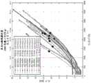
图4A-4B描绘了阻塞检测数据。4A-4B depict blockage detection data.
图5描绘了根据本发明的实施例的监测输液泵的系统状况的方法的流程图。5 depicts a flow diagram of a method of monitoring system conditions of an infusion pump in accordance with an embodiment of the present invention.
图6描绘了根据本发明的实施例的泵系统。Figure 6 depicts a pump system according to an embodiment of the present invention.
图7描绘了根据本发明的实施例的泵系统。Figure 7 depicts a pump system according to an embodiment of the present invention.
图8描绘了根据本发明的实施例的监测用户可佩戴的输液泵中编码器性能的方法的流程图。8 depicts a flowchart of a method of monitoring encoder performance in a user-wearable infusion pump according to an embodiment of the present invention.
虽然各种实施例可修改为各种变型和替代形式,但其具体内容已在图中以示例方式示出,并将详细描述。然而,应当理解,其意图并不是要将所要求保护的发明限制在所描述的特定实施例中。相反,意图是涵盖落在权利要求所定义的主题的精神和范围内的所有变型、等同物和替代物。While the various embodiments are amenable to various modifications and alternative forms, specifics thereof have been shown by way of example in the drawings and will be described in detail. It should be understood, however, that the intention is not to limit the claimed invention to the particular embodiments described. On the contrary, the intention is to cover all modifications, equivalents, and alternatives falling within the spirit and scope of the subject matter defined by the claims.
具体实施方式Detailed ways
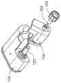
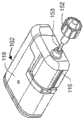
图1A-1C描绘了根据本发明的一个实施例的包括泵102的泵系统。泵102的驱动单元118包括驱动机构122,该驱动机构122与泵102的一次性药筒116中的凹部配合,以将药筒116附接到驱动单元118上,并提供通过套管从药筒116向用户的药剂(诸如胰岛素)输送。根据本发明的实施例的泵系统可以包括泵102以及任何附加组件(例如输液器),泵102包括驱动单元118和药筒116。短长度的管子153可以从药筒116延伸,其中连接器152被设计为附接到这种输液器的对应连接器,该输液器包括从该对应连接器延伸到具有输液部位连接器的输液部位的一定长度的管子,以将药剂输送到该输液部位。关于这种泵的进一步细节可以在2015年5月8日提交的编号14/707,851的美国专利申请和公布号2016/0339172和2017/0049957的美国专利中找到,这些专利申请的每一个在此通过引用而全部纳入本文。1A-1C depict a pump system including a
在一个实施例中,泵102包括控制泵的操作的处理器,并且在一些实施例中,可以以单向或双向模式进行通信,以便例如从单独的设备接收命令和/或其他信号(包括数据),和/或例如向单独的设备发送信号(包括数据)。这样的单独设备可以包括,例如,专用遥控器或智能手机或其他消费电子设备,其执行被配置成使所述设备能够将操作命令传送到泵102的处理器的应用程序。在一些实施例中,处理器还可以向一个或多个独立设备传送信息,例如与设备参数、警报、提醒、泵状态等有关的信息。所述一个或多个设备和泵之间(以及当中)的这种通信可以是单向的或双向的,以便例如在设备和泵之间有效地传输数据、控制泵的操作、更新设备和/或泵上的软件、以及允许在设备和/或泵上查看与泵相关的数据。In one embodiment, the
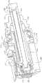
图2A-2E描绘了驱动机构122,该驱动机构利用压电性从携带式输液泵系统中的药筒中分配药剂。一般来说,驱动机构122包括多个压电元件,这些压电元件当被用驱动信号激励时,相对于驱动盘振动以引起驱动盘的旋转运动。驱动盘的旋转运动被转换为推杆的线性运动,该推杆与药筒内的注射器连接,以推进注射器并分配药剂。2A-2E depict
被利用将由马达201引起的陶瓷驱动盘214的旋转运动转化为线性运动的马达组件的主要元件包括驱动管202、导螺杆204和驱动螺母或推杆206。在图2A-2C中可以最清楚地看到,陶瓷驱动盘214与驱动管202耦接(couple),其中驱动管202的主体209延伸穿过陶瓷驱动盘214的开口213,并且陶瓷驱动盘214的主体215邻接驱动管202的凸缘211。陶瓷驱动盘214和驱动管202的这种互连使陶瓷驱动盘214的旋转引起驱动管202的旋转。导螺杆204的近端208被接收在驱动管202的凹部内并与凹部210耦接,这样驱动管202的旋转也使导螺杆204旋转。推杆206的内部螺纹部分217与导螺杆204的外部螺纹212耦接。推杆206的外周216可以是非圆形的,并可滑动地与耦接到前壳体220并包含在前壳体220内的导套218配合,以防止推杆206旋转。这进而使得导螺杆204的旋转能够实现推杆206的线性运动。因此,推杆206被包含在马达组件内并由马达组件直接驱动。驱动尖端234可以附接到推杆206的远端。The main elements of the motor assembly that are utilized to convert the rotational motion of the
在一个实施例中,装置的操作是通过用电驱动信号激励压电马达以使其相对于陶瓷驱动盘214振动来实现的。该振动引起陶瓷驱动盘214的旋转运动。陶瓷驱动盘214的旋转运动使驱动管202和导螺杆204旋转。相互啮合的导螺杆204的螺纹外部部分212和推杆206的内部螺纹部分217以及被导套218限制而不能旋转的推杆206的非圆形周边216,使该旋转运动转化为推杆206的直线运动。当驱动机构122附接到含有药剂的药筒,例如药筒116时,推杆206的线性运动使推杆的驱动尖端234推进药筒中的注射器,以使从药筒中分配药剂。关于这样的驱动系统的进一步细节可以在公布号2017/0049957的美国专利中找到,其先前通过引用并入本文。In one embodiment, operation of the device is accomplished by energizing the piezoelectric motor with an electrical drive signal to vibrate it relative to the
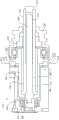
可由根据本发明的实施例的驱动机构利用的另一个特征是光学编码器系统。参照图3A-3C,根据一个实施例的装置可以包括光学编码器集成电路240,其被配置成监视径向围绕驱动管202的外周表面244的标记242(注意,图3B描绘了驱动机构实施例,其中装置的某些后部被去除,而图3C仅描绘了驱动管202,两者都是为了清楚起见)。光电编码器集成电路240可以包括具有集成光源的反射式光学编码器。光源可以定位在驱动管202上的标记242上方,此标记可以是例如预先定义的一系列反光的和非反光的线。通过在驱动管202旋转时跟踪该系列线,集成电路监测驱动管202的旋转位置,该旋转位置指示推杆206的线性位置。虽然本文就驱动管202进行了描述,但应当理解,编码器240可以被利用来监测任何旋转驱动的元件上的标记,该元件被旋转,使得用泵输送药剂。Another feature that may be utilized by drive mechanisms according to embodiments of the present invention is an optical encoder system. 3A-3C, an apparatus according to one embodiment may include an optical encoder integrated
在一个实施例中,光学编码器系统可以监视由驱动管202上的标记242指示的三个输出通道。这些通道可以包括,例如,A通道、B通道和索引通道。对A通道和B通道的监测可以被系统用来确定驱动管的旋转位置、速度和旋转方向。In one embodiment, the optical encoder system can monitor the three output channels indicated by
对索引通道的监测可以服务于多个目的。例如,索引通道可以被配置成,使得对于设定数量的A和B脉冲预期有一个索引通道脉冲。如果在该设定数量的A和B脉冲之后没有检测到该索引通道脉冲,则可以推断出编码器系统可能没有正常工作,并且可以向处理器或其他设备发送一个或多个信号以禁用驱动系统,向用户发送警告或其他信息等。类似地,这种配置可用于确定驱动管是否在编码器系统未打开时运动。一般来说,出现这种情况的原因可能是,为了节省电池电量,编码器只在马达运动之前马上打开,然后在该运动完成后不久就关闭。因此,如果某种故障(如硬件故障、宇宙射线等)使驱动管在编码器断电时旋转,则仅通过监测A、B通道无法确定该故障。将索引脉冲信号与A和B信号进行比较,可以检测出这种故障情况。这种配置可进一步用于确定A和B通道是否按预期工作;如果是这样,则如上所述,针对每个设定数量的A和B脉冲,应接收一个索引脉冲。在所描述的光学编码器系统中,被监测的标记242被设置在系统的部件——驱动管202上,该部件在其他情况下还具有附加的功能目的(旋转导螺杆)。Monitoring of index channels can serve multiple purposes. For example, the index channel may be configured such that one index channel pulse is expected for a set number of A and B pulses. If this index channel pulse is not detected after this set number of A and B pulses, it can be inferred that the encoder system may not be functioning properly, and one or more signals can be sent to the processor or other device to disable the drive system , send a warning or other information to the user, etc. Similarly, this configuration can be used to determine if the drive tube is moving when the encoder system is not turned on. In general, this might be the case because, to save battery power, the encoder only turns on right before the motor moves, and then turns off shortly after that motion is complete. Therefore, if some kind of fault (such as hardware failure, cosmic rays, etc.) causes the drive tube to rotate when the encoder is de-energized, it cannot be determined by monitoring the A, B channels alone. This fault condition can be detected by comparing the index pulse signal with the A and B signals. This configuration can further be used to determine if the A and B channels are working as expected; if so, then as described above, an index pulse should be received for each set number of A and B pulses. In the described optical encoder system, the monitored
本文所述的系统在正常负载条件下一般包括正常量的“滑移”。滑移发生在驱动尖端和驱动盘之间,是指来自驱动尖端的运动的动能,其被转化为热而不是驱动盘的运动。这包括由于惯性引起的启动滑移和由于来自各种来源(例如,球轴承摩擦、套管摩擦、以及来自药筒柱塞摩擦的对驱动螺母的轴向负载)的旋转阻力引起的稳态滑移。在启动时(例如,当马达首次通电时),驱动尖端以一定的速度振动,这种运动几乎瞬间达到稳态,但驱动盘和驱动管组件的惯性使驱动盘-驱动管组件无法与该极高的加速度相匹配,这就造成了启动滑移。在稳态条件下(恒定转速),由于驱动尖端与驱动盘之间有缺点的摩擦连接,因此会出现滑移,并且随着负载的增加,滑移增大且来自驱动尖端的运动的动能更大程度上转化为热,而不是驱动盘的运动。The systems described herein generally include a normal amount of "slip" under normal load conditions. Slip occurs between the drive tip and the drive disc and refers to the kinetic energy from the motion of the drive tip, which is converted into heat rather than the motion of the drive disc. This includes start-up slip due to inertia and steady-state slip due to rotational resistance from various sources (eg, ball bearing friction, sleeve friction, and axial load on the drive nut from cartridge plunger friction) shift. At start-up (for example, when the motor is first powered up), the drive tip vibrates at a certain speed, and this motion reaches steady state almost instantaneously, but the inertia of the drive disc and drive tube assembly prevents the drive disc-drive tube assembly from interacting with the pole The high acceleration is matched, which causes the start-up slip. Under steady state conditions (constant rotational speed), slip occurs due to the defective frictional connection between the drive tip and the drive disc, and as the load increases, the slip increases and the kinetic energy from the motion of the drive tip is more Much of that translates into heat, not motion of the drive disk.
编码器系统也可以间接地用于,例如,监测泵中的压力。在一个实施例中,随着药筒116中压力的增加,需要更多的力来推进注射器和推杆206,相应地,旋转导螺杆204所需的扭矩也增加。进而,如上所述,由于这种增加的扭矩水平,压电马达201和驱动盘214之间的滑移量增加到大于正常量。这种滑移量的增加导致给定量的被标记的驱动管202和导螺杆204的旋转位移需要更长的时间。通过监测给定的旋转位移发生所需的时间,可以确定由于泵中的压力而导致的药筒注射器和推杆206上的高力和低力状况。这使得能够检测一个或多个与泵相关的条件,包括是否存在阻塞、是否存在药筒、泵的驱动系统的一般性能和健康状况等。泵可以包括内部定时器,处理器使用该定时器确定移动完成时间。以这种方式监测泵的状况可以由处理器在上述泵内完成。替代地,单独的设备,例如专用遥控器或智能手机,可以从泵处理器接收与编码器有关的数据,监测该数据,并做出与泵状况有关的判断。这样的数据也可以被记录到泵和/或单独的设备的存储器中,并且被进一步使用诊断工具来分析,例如可以驻留在服务器、诊断和/或维修设备等上。The encoder system can also be used indirectly, for example, to monitor the pressure in a pump. In one embodiment, as the pressure in the
仅举例说明(因为这样的时间可以根据特定的设计配置而显著变化),在正常的系统操作期间(当推杆推进药筒注射器以分配药剂时),用于驱动管和导螺杆旋转给定距离的典型移动完成时间可以在约20毫秒到约40毫秒的范围内。当该给定距离的移动完成时间比约40毫秒长时,这可能表明系统中存在额外的滑移,因为并非所有的压电能量被转化为驱动盘和驱动管的旋转运动——以及推杆的相应线性运动。然后,处理器可以推断,系统中可能存在诸如上述讨论的若干条件中的一种或多种。类似地,可能存在没有检测到旋转运动的情况。这样的情况可能表明,足够的压电能量正在滑移中损失,使得推杆在观察/监测的时间段内根本没有线性前进。因此,虽然系统在此一般被称为检测“移动完成时间”,但应当理解,在没有检测到移动的情况下,没有实际的移动,而移动完成时间反而是指达到阈值时间段,其中没有移动表示系统状况。By way of example only (as such times can vary significantly depending on the particular design configuration), during normal system operation (when the pushrod advances the cartridge syringe to dispense medicament), for driving the tube and lead screw to rotate a given distance A typical move completion time can be in the range of about 20 milliseconds to about 40 milliseconds. When the movement for that given distance takes longer than about 40 milliseconds to complete, this may indicate additional slippage in the system, as not all piezoelectric energy is converted into rotational motion of the drive disk and drive tube - and the pushrod the corresponding linear motion. The processor may then infer that one or more of several conditions such as those discussed above may exist in the system. Similarly, there may be situations where rotational motion is not detected. Such a situation may indicate that enough piezoelectric energy is being lost in the slip that the pushrod is not advancing linearly at all during the observed/monitored time period. Thus, while the system is generally referred to herein as detecting a "movement completion time," it should be understood that in the event that no movement is detected, there is no actual movement, and instead the movement completion time refers to reaching a threshold period of time in which no movement is made Indicates system status.
当没有检测到旋转运动时,意味着没有足够量的压电能量被转换为实现驱动盘的所需旋转运动程度,处理器可以推断系统中可能存在若干状况中的一种或多种。这样的状况包括,例如,驱动系统被卡住了,药筒是空的和/或推杆已达到其全行程状态。系统的状况可以由处理器基于推杆相对于由编码器系统指示的推杆的完全缩回和/或完全伸展状态的位置,以及系统计算出的药剂在储存器中的剩余量来确定。如果推杆处于其完全伸展状态,那么没有进一步的旋转运动来指示推杆已达到其完全伸展的行程状态。如果推杆未完全伸展,则可基于处理器已跟踪的药剂在储存器中的剩余量来确定系统的状况。如果处理器已经确定储存器中仅剩余少量药剂,例如,5至10个单位的药剂或更少,但当马达被驱动时,驱动管没有旋转运动,则系统可以推断药筒是空的。如果没有旋转运动,但处理器已经确定有大量的药剂,例如,100单位的药剂剩余在药筒内,则处理器可以推断驱动系统被卡住。When no rotational motion is detected, meaning that a sufficient amount of piezoelectric energy is not being converted to achieve the desired degree of rotational motion of the drive disk, the processor can infer that one or more of several conditions may exist in the system. Such conditions include, for example, the drive system is stuck, the cartridge is empty and/or the pushrod has reached its full stroke state. The condition of the system may be determined by the processor based on the position of the push rod relative to the fully retracted and/or fully extended state of the push rod as indicated by the encoder system, and the system's calculated amount of medicament remaining in the reservoir. If the push rod is in its fully extended state, there is no further rotational movement to indicate that the push rod has reached its fully extended stroke state. If the pushrod is not fully extended, the condition of the system can be determined based on the amount of medicament remaining in the reservoir that has been tracked by the processor. If the processor has determined that only a small amount of medicament remains in the reservoir, eg, 5 to 10 units of medicament or less, but there is no rotational movement of the drive tube when the motor is driven, the system can conclude that the cartridge is empty. If there is no rotational movement, but the processor has determined that there is a substantial amount of medicament, eg, 100 units of medicament remaining in the cartridge, the processor may conclude that the drive system is stuck.
当驱动管旋转,使得推杆在马达驱动时线性移动,但移动完成时间比预期长时,这可能表明系统中存在高压状况,例如流体管线中的阻塞。例如,如果有大约20ms到大约40ms之间的预期移动完成时间,则大约50ms的移动完成时间可以使处理器推断出存在阻塞,并且可选择地可以采取任何次数的行动作为其结果,并且如下所述。When the drive tube rotates so that the pushrod moves linearly when the motor drives, but the movement takes longer than expected to complete, this may indicate a high pressure condition in the system, such as a blockage in a fluid line. For example, if there is an expected move completion time of between about 20ms and about 40ms, then a move completion time of about 50ms may allow the processor to deduce that there is a blocking, and may optionally take any number of actions as a result of it, and as follows described.
图4A-4B描绘了阻塞检测测试数据。具体而言,这些数据显示了在夹紧泵的输液器管子以模拟阻塞后本文所述的泵系统的一个实施例如何反应。图4A描绘了作为以磅每平方英寸为单位的泵中压力(x轴)的函数的以毫秒为单位的移动持续时间或完成时间(y轴)。图4B描绘了相同的测试数据,其中泵中的压力作为以计数(例如,驱动管上的标记的数量)为单位的编码器位置的函数。从图4A中可以看出,随着泵中压力的增加,驱动管运动或旋转给定距离所需的时间增加。每个较小的点10代表顺序的50计数(50-count)的移动。较大的点12对应于需要大约50ms完成的50计数的移动。该50毫秒阈值与泵中约18psi至约27psi的压力范围相关。因为流体药筒和输液器管子不是一个完全刚性的系统,当发生阻塞时,驱动管仍然可以旋转,推杆仍然可以平移以将药剂泵出,但是当流体压力增加时,系统将弯曲,而不是将药剂输送给患者。图4B中描绘的编码器定位可用于确定在检测到阻塞之前未输送的药剂量。如在图4B中可以看到,在测试数据中,由于检测到的阻塞,大约12微升的胰岛素和大约23微升的胰岛素的范围未被输送。4A-4B depict congestion detection test data. Specifically, these data show how one embodiment of the pump system described herein responds after clamping the pump's infusion set tubing to simulate an occlusion. Figure 4A depicts movement duration or completion time in milliseconds (y-axis) as a function of pressure in the pump in pounds per square inch (x-axis). Figure 4B depicts the same test data with pressure in the pump as a function of encoder position in counts (eg, the number of markings on the drive tube). As can be seen in Figure 4A, as the pressure in the pump increases, the time required to drive the tube to move or rotate a given distance increases. Each
给定的旋转位移发生所需的时间也可以被监测以检测低压条件。如上所述,导螺杆204的旋转引起推杆206的线性运动,使得推杆的驱动尖端234接触并推进药筒内的注射器,以使药剂从药筒116中被分配。因此,在正常的系统操作过程中,存在来自药筒注射器的施加在推杆上的一定水平的力。如果推杆不与注射器接触,则该力不存在,这将导致较低的移动完成时间。例如,如果当泵分配药剂时的典型移动完成时间在约20和约40毫秒之间,小于约20ms的移动完成时间可以表明推杆没有与注射器接触。这可以表明药筒不存在(视觉上将是明显的),并且还可以在药筒填充后的初始使用期间的药筒预注(priming)过程中用来确定推杆何时接触了注射器柱塞。确定推杆未与药筒注射器接触的能力也提供了一个额外的安全特性,因为它表明当马达启动时,泵可能没有分配药剂。The time required for a given rotational displacement to occur can also be monitored to detect low pressure conditions. As described above, rotation of the
系统可以基于检测到的系统状况采取各种行动。系统可以在泵的用户界面上和/或在远程控制设备(例如专用遥控器或智能手机)的用户界面上提供与检测到的状况相关的警告或警报。这样的警告或警报还可以包括听觉和/或振动警报。例如,如果系统已经确定存在阻塞,则可以发出阻塞警报。这样的警报可以通知用户已经检测到阻塞,并指示用户清除阻塞。在一些实施例中,用户可以通过提供用于清除阻塞(或其他状况)的指示和/或建议的警报进入故障排除模式。用户可以确认并清除警报。如果在清除警报之前阻塞没有得到适当的补救,系统将再次检测到阻塞并提供另一个警报。对于其他检测到的系统状况,可以以类似的方式提供相应的警报或警告,例如药筒空了或丢失了,驱动系统被卡住了,以及推杆已经到达其行程的终点。在一些实施例中,当阻塞或其他系统状况警报被发出时,系统也自动停止药剂输送,直到警报被清除。The system can take various actions based on detected system conditions. The system may provide warnings or alarms related to detected conditions on the user interface of the pump and/or on the user interface of a remote control device (eg, a dedicated remote control or smartphone). Such warnings or alerts may also include audible and/or vibratory alerts. For example, if the system has determined that there is a blockage, a blockage alert can be issued. Such an alert can notify the user that a blockage has been detected and instruct the user to clear the blockage. In some embodiments, a user may enter a troubleshooting mode by providing an indication and/or a suggested alert for clearing an obstruction (or other condition). The user can acknowledge and clear the alert. If the blockage is not properly remedied before the alarm is cleared, the system will detect the blockage again and provide another alarm. Corresponding alerts or warnings can be provided in a similar fashion for other detected system conditions, such as an empty or missing cartridge, a stuck drive system, and a push rod that has reached the end of its travel. In some embodiments, when an occlusion or other system condition alarm is issued, the system also automatically stops medicament delivery until the alarm is cleared.
图5描绘了用于监测本文所述的输液泵中的系统状况300的方法步骤的流程图。在步骤302,监测给定旋转距离的移动完成时间,并在步骤304确定每个完成时间是否在预期范围内。如果时间在预期范围内,则该方法在步骤302继续监测移动完成时间。如果时间长于预期范围,则在步骤306确定在监测时间段内是否检测到移动。如果检测到移动——意味着驱动管按预期旋转,但移动时间长于预期——那么系统在步骤308确定存在阻塞,并可在步骤310发出阻塞警报。5 depicts a flowchart of method steps for monitoring
仍然参照图5,如果在监测期间没有检测到旋转运动,则系统接下来在步骤312确定由编码器系统指示的推杆的位置。如果在步骤314处确定推杆的位置是完全伸展的,则系统可以在步骤316处确定推杆已经达到其全行程状态,并且可以在步骤318处通知用户。然后,驱动系统将需要重新设置,以便输送更多的药剂。如果推杆尚未达到其全行程状态,则系统在步骤320处确定对泵中剩余药剂量的估计。如果系统在步骤322处估计泵中只剩余极少量的药剂,例如,在大约5和大约10个单位的药剂之间或更少,则在步骤324处,系统确定泵被认为药剂空了,并且可以在步骤326处通知用户泵被认为是空的,并且需要重新填充或更换泵药筒。如果系统估计泵中仍有较多量的药剂,则系统在步骤328处确定驱动系统被卡住,并且可以在步骤330处通知用户驱动系统被卡住并且,例如,应检查系统。Still referring to FIG. 5 , if no rotational motion is detected during the monitoring period, the system next determines the position of the pushrod indicated by the encoder system at
该系统可以被调整以修改本发明各种实施例中本文描述的各种警报和警告的灵敏度设置。如上所述,系统中典型的移动完成时间可以在约20至约40毫秒的范围内。可以通过改变在触发警报之前移动必须花的时间量来调整警报灵敏度。例如,在上面讨论的一个实施例中,当移动完成时间为50毫秒或更长时间时,就会触发警报。为了提高警报灵敏度,可以将警报时间阈值减小到40毫秒。类似地,可以通过增大警报时间阈值来降低报警灵敏度,例如,可以增大到约60毫秒。此外,检测阈值可以基于给定驱动系统的特性来设置,以考虑系统与系统之间的可变性,使得每个系统可以具有不同的移动持续时间阈值,以降低当检测到阻塞时系统之间的漏掉药剂量的变化。The system can be adjusted to modify the sensitivity settings of the various alarms and warnings described herein in various embodiments of the invention. As noted above, typical movement completion times in the system may be in the range of about 20 to about 40 milliseconds. Alarm sensitivity can be adjusted by changing the amount of time a movement must take before an alarm is triggered. For example, in one embodiment discussed above, an alarm is triggered when the move completes in 50 milliseconds or more. To increase alert sensitivity, the alert time threshold can be reduced to 40 ms. Similarly, the alarm sensitivity can be reduced by increasing the alarm time threshold, eg, to about 60 milliseconds. Additionally, detection thresholds can be set based on the characteristics of a given drive system to account for system-to-system variability, so that each system can have a different movement duration threshold to reduce inter-system variability when an obstruction is detected Missing dose changes.
如公开号2017/0049957的美国专利中所公开的,在一些实施例中,携带式输液泵可以在主编码器240之外还包括辅助编码器241。在一个实施例中,辅助编码器241可以如图6所示定位,以便也监测驱动管上的标记。在这样的一个实施例中,驱动管202可以在针对图3A-3C讨论的标记242之外还包括用于通过辅助编码器241监测的第二组光学标记。利用一对编码器240、241可以实现信号冗余,以防止单个编码器故障导致药剂的过度输送。替代地,辅助光学编码器,辅助编码器可以是磁性编码器、霍尔效应编码器或本领域已知的其它类型的编码器。As disclosed in US Patent Publication No. 2017/0049957, in some embodiments, the portable infusion pump may include an
在一些实施例中,辅助编码器可以是磁性传感器,用于通过向用于监测主编码器性能的算法提供输入来监测主编码器的性能。参照图7,磁性传感器241可以是霍尔效应磁性传感器,其感测设置于驱动管202或其他可旋转元件上的磁体243。在其它实施例中,磁性传感器可以是簧片开关。当驱动管202旋转时,磁体243将随之旋转。每次磁体243经过磁性传感器241时,传感器将检测到磁体243,使得装置的处理器可以利用来自磁性传感器243的信息进一步跟踪系统状况。虽然被描绘为采用单个磁体243,但在各种实施例中,可以在驱动管202周围以规则或不规则的间隔布置两个或多个磁体。这样的系统将使磁性传感器241在驱动管202的每一次旋转中被触发一次以上,从而增加了系统对任何主编码器240误差的灵敏度。In some embodiments, the secondary encoder may be a magnetic sensor for monitoring the performance of the primary encoder by providing input to an algorithm for monitoring the performance of the primary encoder. 7, the
因为主编码器240相对于标记242工作,所以当电源关闭或电源循环时,它可以轻微漂移(drift),以减少泵的功耗。编码器240也可以经历其他问题——如前所述——其中每个问题都可能导致一个或多个性能错误和/或其他问题。因此,如上所述,在各种实施例中,辅助编码器241可用于监测主编码器240的性能,以确保主编码器正确跟踪驱动管202的旋转位置和速度。这样的系统在检测主编码器系统故障方面是有用的,以防止这样的故障导致输送错误,这可能对患者造成严重医疗后果。因此,使用如本文所述的磁性编码器系统能够以极低的功率操作进行编码器监测。Because the
在一个实施例中,磁性传感器241可以在药筒116更换、泵预注或涉及使用马达201以实现导螺杆204的回转(rewind)或伸展的其他操作期间监测主编码器240的性能。磁性传感器241通过感测磁体243,可以监测驱动管202在一个或多个上述程序期间的旋转次数,并将检测到的旋转次数与主编码器240检测到的旋转次数进行比较。如果每个编码器检测到的旋转次数相同,则不需要采取进一步的行动,并且泵可以进行正常的泵操作。如果次数不同,则其可表明主编码器的操作存在错误,并且警告或警报可以被发出,以向用户通知该错误。In one embodiment, the
如果在主编码器的操作中检测到错误,可以向处理器发送一个或多个信号以禁用驱动系统。任选地,可以通知用户,例如,驱动系统已被自动禁用,以请求用户确认以禁用驱动系统等。在一些实施例中,系统可以自动地,或者通过用户提示,运行一个或多个自测试以确认错误。这样的自测试可以涉及,例如,缩回导螺杆、操作马达和比较辅助磁性编码器读数和主光学编码器读数和/或确认磁性检测来自磁体而不是可能由例如与驱动系统无关的外力触发的错误检测。在一些实施例中,如果确认了错误,如果在不自动自测试以确认错误的实施例中检测到了错误,可以指示用户将泵返回到制造商和/或联系制造商以例如获得更换。If an error is detected in the operation of the master encoder, one or more signals can be sent to the processor to disable the drive system. Optionally, the user may be notified that, for example, the drive system has been automatically disabled, to request confirmation from the user to disable the drive system, or the like. In some embodiments, the system may run one or more self-tests to confirm errors, either automatically, or through a user prompt. Such self-tests may involve, for example, retracting the lead screw, operating the motor and comparing the secondary magnetic encoder reading to the primary optical encoder reading and/or confirming that the magnetic detection is from the magnet and not possibly triggered by, for example, an external force unrelated to the drive system Error detection. In some embodiments, if an error is confirmed, the user may be instructed to return the pump to the manufacturer and/or contact the manufacturer to obtain a replacement, for example, if an error is detected in embodiments that do not automatically self-test to confirm the error.
在正常的泵送操作期间,例如,当用泵向患者输送药剂时,也可以利用磁性传感器241来监测主编码器240的性能。如上所述,主编码器240在装置操作期间监测驱动管202上的多个标记242或计数。在常规的药剂输送期间,在给定的时间段内监测到的计数数量与在该时间段内输送的药剂量相对应。因此,重要的是,主编码器正确和准确地测量编码器计数的数量。当磁性传感器241被触发时,可以将由主编码器240测量的编码器计数的数量与预期发生的编码器计数的目标数量或范围进行比较。例如,在在驱动管202上采用一个磁体243的实施例中,每次磁性传感器241被触发时,驱动管202将经历一次完整的旋转。因此,可以将主编码器测量的编码器计数的数量与预期的编码器计数的数量或范围进行比较,如果该数量与预期数量相同或在预期范围内,则可以不间断地继续进行泵送操作。如果不是,则可以通知用户错误和/或如上所述禁用驱动系统。这样的错误可能由于主编码器在给定的旋转内被关闭和开启而发生,使得有可能漏掉计数或发生额外的计数。The performance of the
额外地或替代性地监测和比较离散编码器计数的数量之外,磁性传感器241还可用于确定在正常泵送操作期间由主编码器241测量的驱动管202的完整旋转的次数是否准确。如本文所述的泵中的驱动管202可以经历若干次完整旋转来输送给定药筒中包含的药剂。因此,对主编码器性能的进一步检查可以是将主编码器测量的驱动管202的完整旋转的次数与磁性传感器241确定的旋转次数进行比较。因此,例如,在有一个每次旋转其在单个绝对位置处触发磁性传感器241一次的磁体243的情况下,磁性传感器被触发的次数可以与主编码器243测量的旋转次数进行比较。在采用多于一个的磁性传感器的实施例中,不同的磁性传感器触发次数将等同于待与主编码器比较的一次完整旋转,或者可以监测和比较较小的旋转量,例如,半转。如果主编码器和磁性编码器确定的旋转次数相同,则可以不间断地继续泵送操作。如果不同,则可以通知用户错误和/或如上所述禁用驱动系统。In addition or alternatively to monitoring and comparing the number of discrete encoder counts, the
在用户发起的或系统的自动自测试期间,磁性编码器还可用于监测主编码器240的性能。由于测试仅仅是为了测试主编码器的性能而进行的,因此系统不会输送任何药剂,而不管是否存在内部和/或面向用户的(例如,泵或远程设备上的图形用户界面,通过振动和/或声音手段等)错误指示或其他提示。这样的测试可以其他方式在正常的泵操作期间以类似于上述编码器监测的方式进行,其中由主编码器240确定的计数和/或旋转的数量与由磁性编码器系统监测的预期计数和/或旋转的数量或范围进行比较。The magnetic encoder may also be used to monitor the performance of the
现在参考图8,示出了描绘用于监测携带式输液泵中的主编码器的性能的步骤400的流程图。在步骤402处,发起一个或多个泵操作,例如,如上所述的正常泵操作、药筒更换、自测试等。在步骤404和406,分别用主编码器240和辅助编码器241监测驱动管或系统的其他旋转驱动元件的旋转位置。如上所述,在各种实施例中,主编码器240可以是监测驱动管202上的标记242的光学编码器,而辅助编码器241可以是检测驱动管202上的磁体243的磁性传感器。在步骤408,如本文所述,比较由两个编码器检测的信息。如果在步骤410处,该比较表明来自编码器的信息相互对应,例如,当磁性传感器被触发时,由每个编码器测量的旋转次数和/或由主编码器测量的编码器计数的数量匹配或在目标范围内,则继续进行泵送操作。如果在步骤412中该比较表明来自编码器的信息彼此不对应,则在步骤416中由处理器确定编码器故障。然后可以发出一个或多个错误消息和/或然后在步骤414处如上所述禁用泵送系统。Referring now to FIG. 8, a
此外,通过引用全部纳入本文的还有共同拥有的以下编号的美国专利:8,287,495;8,408,421;8,448,824;8,573,027;8,650,937;8,986,523;9,173,998;9,180,242;9,180,243;9,238,100;9,242,043;9,335,910;9,381,271;9,421,329;9,486,171;9,486,571;9,492,608;9,503,526;9,555,186;9,565,718;9,603,995;9,669,160;9,715,327;9,737,656;9,750,871;9,867,937;9,867,953;9,940,441;9,993,595;10,016,561和10,201,656。还有共同拥有的以下公布号的美国专利:2009/0287180;2012/0123230;2013/0053816;2014/0276419;2014/0276420;2014/0276423;2014/0276569;2014/0276570;2015/0182693;2016/0082188;2017/0049957;2017/0142658;2017/0182248;2017/0250971;2018/0021514;2018/0071454和2018/0193555。还有共同拥有的申请号14/707,851的美国专利;以及共同拥有的以下序列号的美国临时申请:61/911,576;61/920,902;61/920,914;61/920,940;62/139,275;62/352,164;62/545,228;62/655,516;62/677,433;62/743,901;62/784,939;和62/784,949。此外,通过引用全部纳入本文的还有共同拥有的以下编号的美国专利:8,287,495;8,408,421;8,448,824;8,573,027;8,650,937;8,986,523;9,173,998;9,180,242;9,180,243;9,238,100;9,242,043;9,335,910;9,381,271;9,421,329;9,486,171;9,486,571 ;9,492,608;9,503,526;9,555,186;9,565,718;9,603,995;9,669,160;9,715,327;9,737,656;9,750,871;9,867,937;9,867,953;9,940,441;9,993,595;10,016,561和10,201,656。 There are also co-owned US patents with the following publication numbers: 2009/0287180; 2012/0123230; 2013/0053816; 2014/0276419; 2014/0276420; 0082188; 2017/0049957; 2017/0142658; 2017/0182248; 2017/0250971; 2018/0021514; There are also commonly owned U.S. Patent Application No. 14/707,851; and commonly owned U.S. Provisional Applications with the following serial numbers: 61/911,576; 61/920,902; 61/920,914; 61/920,940; 62/139,275; 62/545,228; 62/655,516; 62/677,433; 62/743,901; 62/784,939; and 62/784,949.
在此进一步通过引用全文纳入的是以下编号的美国专利:8,601,465;8,502,662;8,452,953;8,451,230;8,449,523;8,444,595;8,343,092;8,285,328;8,126,728;8,117,481;8,095,123;7,999,674;7,819,843;7,782,192;7,109,878;6,997,920;6,979,326;6,936,029;6,872,200;6,813,519;6,641,533;6,554,798;6,551,276;6,295,506;和5,665,065。在此进一步通过引用全文纳入的是以下编号的美国专利:8,601,465;8,502,662;8,452,953;8,451,230;8,449,523;8,444,595;8,343,092;8,285,328;8,126,728;8,117,481;8,095,123;7,999,674;7,819,843;7,782,192;7,109,878;6,997,920;6,979,326;6,936,029 ; 6,872,200; 6,813,519; 6,641,533; 6,554,798; 6,551,276; 6,295,506; and 5,665,065.
本文已经描述了系统、装置和方法的各种实施例。这些实施例仅以举例的方式给出,而不是旨在限制所要求保护的发明的范围。此外,应该理解的是,已经描述的实施例的各种特征可以以各种方式组合,以产生许多额外的实施例。此外,虽然已经描述了用于所公开的实施例的各种材料、尺寸、形状、配置和位置等,但除了所公开的那些之外,还可以利用其他的,而不超出所要求保护的发明的范围。Various embodiments of systems, apparatus and methods have been described herein. These examples are given by way of example only, and are not intended to limit the scope of the claimed invention. Furthermore, it should be understood that the various features of the described embodiments may be combined in various ways to yield numerous additional embodiments. In addition, while various materials, dimensions, shapes, configurations, locations, etc. have been described for the disclosed embodiments, others in addition to those disclosed may be utilized without departing from the claimed invention range.
相关领域的普通技术人员将认识到,本主题可包含比上述任何单个实施例中说明的特征少的特征。此处描述的实施例并不意味着是对本主题的各种特征可以组合的方式的穷尽介绍。因此,这些实施例并不是相互排斥的特征组合;相反,如本领域普通技术人员所理解的那样,各种实施例可以包括选自不同的单个实施例的不同单个特征的组合。此外,除非另有说明,否则针对一个实施例所描述的元件可以在其他实施例中实施,即使在这些实施例中没有描述。One of ordinary skill in the relevant art will recognize that the subject matter may contain fewer features than those illustrated in any single embodiment above. The embodiments described herein are not meant to be an exhaustive introduction to the ways in which various features of the subject matter may be combined. Thus, these embodiments are not mutually exclusive combinations of features; rather, as understood by those of ordinary skill in the art, various embodiments may include combinations of different individual features selected from different single embodiments. Furthermore, unless otherwise indicated, elements described with respect to one embodiment can be implemented in other embodiments even if not described in those embodiments.
虽然从属权利要求在权利要求书中可以是指与一个或多个其他权利要求的特定组合,但其他实施例也可以包括从属权利要求与每个其他从属权利要求的主题的组合,或者一个或多个特征与其他从属或独立权利要求的组合。除非说明不打算进行特定的组合,否则在此提出这样的组合。Although dependent claims may be referred to in the claims in specific combinations with one or more other claims, other embodiments may also include combinations of dependent claims with the subject matter of each other dependent claim, or one or more This feature is combined with other dependent or independent claims. Unless it is stated that a specific combination is not intended, such combination is proposed herein.
任何通过引用上述文献的并入都是有限的,这样就不会并入与本文明确的公开矛盾的主题。任何通过引用上述文献的并入都被进一步限制,使得文献中包含的任何权利要求都不会通过引用而纳入本文。任何通过引用上述文献的并入还受到进一步的限制,使得文献中提供的任何定义不会通过引用而纳入本文,除非明确包含在本文中。Any incorporation by reference of the above documents is limited so as not to incorporate subject matter that is inconsistent with the express disclosure herein. Any incorporation by reference of the above documents is further limited such that no claims contained in the documents are incorporated herein by reference. Any incorporation by reference of the above documents is further limited such that any definitions provided in the documents are not incorporated herein by reference unless expressly included herein.
为了解释权利要求的目的,明确地旨在不援引35U.S.C.§112(f)的规定,除非权利要求中记载了具体的术语“手段”或“步骤”。For purposes of claim interpretation, it is expressly intended not to invoke the provisions of 35 U.S.C. § 112(f) unless the specific term "means" or "step" is recited in the claim.
Claims (19)
Applications Claiming Priority (5)
| Application Number | Priority Date | Filing Date | Title |
|---|---|---|---|
| US201862626430P | 2018-02-05 | 2018-02-05 | |
| US62/626,430 | 2018-02-05 | ||
| US201862632294P | 2018-02-19 | 2018-02-19 | |
| US62/632,294 | 2018-02-19 | ||
| PCT/US2019/016466WO2019152908A1 (en) | 2018-02-05 | 2019-02-04 | Methods and systems for detecting infusion pump conditions |
Publications (2)
| Publication Number | Publication Date |
|---|---|
| CN111936182Atrue CN111936182A (en) | 2020-11-13 |
| CN111936182B CN111936182B (en) | 2022-08-23 |
Family
ID=67476293
Family Applications (1)
| Application Number | Title | Priority Date | Filing Date |
|---|---|---|---|
| CN201980023533.2AActiveCN111936182B (en) | 2018-02-05 | 2019-02-04 | Method and system for detecting the condition of an infusion pump |
Country Status (4)
| Country | Link |
|---|---|
| US (2) | US11458246B2 (en) |
| EP (1) | EP3749390A4 (en) |
| CN (1) | CN111936182B (en) |
| WO (1) | WO2019152908A1 (en) |
Families Citing this family (9)
| Publication number | Priority date | Publication date | Assignee | Title |
|---|---|---|---|---|
| US10279106B1 (en) | 2014-05-08 | 2019-05-07 | Tandem Diabetes Care, Inc. | Insulin patch pump |
| US9993595B2 (en) | 2015-05-18 | 2018-06-12 | Tandem Diabetes Care, Inc. | Patch pump cartridge attachment |
| US10279107B2 (en) | 2015-08-20 | 2019-05-07 | Tandem Diabetes Care, Inc. | Drive mechanism for infusion pump |
| JP7249348B2 (en)* | 2017-12-28 | 2023-03-30 | サノフイ | Sensor device for attachment to injection device |
| US10888655B2 (en) | 2019-02-19 | 2021-01-12 | Tandem Diabetes Care, Inc. | System and method of pairing an infusion pump with a remote control device |
| EP3946514A4 (en) | 2019-03-26 | 2022-12-21 | Tandem Diabetes Care, Inc. | Method of pairing an infusion pump with a remote control device |
| US12138425B2 (en) | 2019-05-21 | 2024-11-12 | Tandem Diabetes Care, Inc. | System and method for incorporating exercise into closed-loop diabetes therapy |
| CN112767659B (en)* | 2020-12-31 | 2022-05-10 | 杭州堃博生物科技有限公司 | Warning method, device and system for radio frequency operating system and radio frequency host |
| US20250108162A1 (en) | 2023-09-29 | 2025-04-03 | Tandem Diabetes Care, Inc. | Infusion pump with multi-cgm compatibility |
Citations (12)
| Publication number | Priority date | Publication date | Assignee | Title |
|---|---|---|---|---|
| US5236416A (en)* | 1991-05-23 | 1993-08-17 | Ivac Corporation | Syringe plunger position detection and alarm generation |
| US5522799A (en)* | 1993-12-17 | 1996-06-04 | Sharp Kabushiki Kaisha | Fluid infusion pump capable of detecting erroneous tube displacement |
| US20030163090A1 (en)* | 2002-02-28 | 2003-08-28 | Blomquist Michael L. | Syringe pump control systems and methods |
| US20050020980A1 (en)* | 2003-06-09 | 2005-01-27 | Yoshio Inoue | Coupling system for an infusion pump |
| US20070062250A1 (en)* | 2005-09-19 | 2007-03-22 | Lifescan, Inc. | Malfunction Detection With Derivative Calculation |
| CN101189431A (en)* | 2005-04-13 | 2008-05-28 | 雅培糖尿病护理公司 | Variable volume, shape memory actuated insulin dispensing pump |
| CN103228303A (en)* | 2010-09-24 | 2013-07-31 | 佩佛罗有限责任公司 | Infusion Pump |
| US20130204174A1 (en)* | 2009-12-28 | 2013-08-08 | Bo Olde | Method and device for detecting a fault condition |
| CN103768679A (en)* | 2014-02-20 | 2014-05-07 | 江苏多维科技有限公司 | Precision injector pump and manufacturing method thereof |
| DE102015104786A1 (en)* | 2015-03-27 | 2016-09-29 | Pfm Medical Tpm Gmbh | Monitoring an infusion pump |
| US20170049957A1 (en)* | 2015-08-20 | 2017-02-23 | Tandem Diabetes Care, Inc. | Drive mechanism for infusion pump |
| JP2017131675A (en)* | 2017-03-07 | 2017-08-03 | テルモ株式会社 | Syringe pump |
Family Cites Families (134)
| Publication number | Priority date | Publication date | Assignee | Title |
|---|---|---|---|---|
| SE436675B (en) | 1975-08-12 | 1985-01-14 | Ki Politekhnichsky I Im 50 Let | ELECTRIC ENGINE OPERATED BY PIEZOELECTRIC FORCES |
| US4741736A (en) | 1986-12-10 | 1988-05-03 | I-Flow Corporation | Programmable infusion pump |
| US5097122A (en) | 1990-04-16 | 1992-03-17 | Pacesetter Infusion, Ltd. | Medication infusion system having optical motion sensor to detect drive mechanism malfunction |
| CN1066967C (en) | 1993-07-17 | 2001-06-13 | 邱峰 | Portable micro pump |
| US5795327A (en) | 1995-03-06 | 1998-08-18 | Sabratek Corporation | Infusion pump with historical data recording |
| US6120460A (en) | 1996-09-04 | 2000-09-19 | Abreu; Marcio Marc | Method and apparatus for signal acquisition, processing and transmission for evaluation of bodily functions |
| US6786420B1 (en) | 1997-07-15 | 2004-09-07 | Silverbrook Research Pty. Ltd. | Data distribution mechanism in the form of ink dots on cards |
| AUPO799197A0 (en) | 1997-07-15 | 1997-08-07 | Silverbrook Research Pty Ltd | Image processing method and apparatus (ART01) |
| DE19717107B4 (en) | 1997-04-23 | 2005-06-23 | Disetronic Licensing Ag | System of container and drive device for a piston, which is held in the container containing a drug fluid |
| US7714889B2 (en) | 1997-07-15 | 2010-05-11 | Silverbrook Research Pty Ltd | Digital camera using exposure information for image processing |
| US6690419B1 (en) | 1997-07-15 | 2004-02-10 | Silverbrook Research Pty Ltd | Utilising eye detection methods for image processing in a digital image camera |
| US6879341B1 (en) | 1997-07-15 | 2005-04-12 | Silverbrook Research Pty Ltd | Digital camera system containing a VLIW vector processor |
| US7551202B2 (en) | 1997-07-15 | 2009-06-23 | Silverbrook Research Pty Ltd | Digital camera with integrated inkjet printer |
| AUPO798697A0 (en) | 1997-07-15 | 1997-08-07 | Silverbrook Research Pty Ltd | Data processing method and apparatus (ART51) |
| US7107706B1 (en) | 1997-08-14 | 2006-09-19 | Promdx Technology, Inc. | Ergonomic systems and methods providing intelligent adaptive surfaces and temperature control |
| US6158431A (en) | 1998-02-13 | 2000-12-12 | Tsi Incorporated | Portable systems and methods for delivery of therapeutic material to the pulmonary system |
| US6468242B1 (en) | 1998-03-06 | 2002-10-22 | Baxter International Inc. | Medical apparatus with patient data recording |
| US7083108B2 (en) | 1998-07-10 | 2006-08-01 | Silverbrook Research Pty Ltd | Redundantly encoded data structure for encoding a surface |
| US7193521B2 (en) | 1998-10-29 | 2007-03-20 | Medtronic Minimed, Inc. | Method and apparatus for detecting errors, fluid pressure, and occlusions in an ambulatory infusion pump |
| US7621893B2 (en) | 1998-10-29 | 2009-11-24 | Medtronic Minimed, Inc. | Methods and apparatuses for detecting occlusions in an ambulatory infusion pump |
| CA2345439C (en) | 1998-10-29 | 2005-08-09 | Minimed, Inc. | Compact pump drive system |
| US7766873B2 (en) | 1998-10-29 | 2010-08-03 | Medtronic Minimed, Inc. | Method and apparatus for detecting occlusions in an ambulatory infusion pump |
| US6423035B1 (en) | 1999-06-18 | 2002-07-23 | Animas Corporation | Infusion pump with a sealed drive mechanism and improved method of occlusion detection |
| EP1194069B1 (en) | 1999-07-08 | 2006-03-22 | Steffen Dr.-Ing. Leonhardt | Device for measuring the blood-sugar level in humans |
| US6413254B1 (en) | 2000-01-19 | 2002-07-02 | Medtronic Xomed, Inc. | Method of tongue reduction by thermal ablation using high intensity focused ultrasound |
| CN100492693C (en) | 2000-03-23 | 2009-05-27 | 伊利普特克谐振调节器股份公司 | Vibration motor and method of making and using same |
| US6485465B2 (en) | 2000-03-29 | 2002-11-26 | Medtronic Minimed, Inc. | Methods, apparatuses, and uses for infusion pump fluid pressure and force detection |
| US6669669B2 (en) | 2001-10-12 | 2003-12-30 | Insulet Corporation | Laminated patient infusion device |
| EP1328346A2 (en) | 2000-10-06 | 2003-07-23 | Protasis Corporation | Microfluidic substrate assembly and method for making same |
| DE10057832C1 (en) | 2000-11-21 | 2002-02-21 | Hartmann Paul Ag | Blood analysis device has syringe mounted in casing, annular mounting carrying needles mounted behind test strip and being swiveled so that needle can be pushed through strip and aperture in casing to take blood sample |
| EP1381408A4 (en) | 2001-02-22 | 2007-06-13 | Insulet Corp | Modular infusion device and method |
| US7141812B2 (en) | 2002-06-05 | 2006-11-28 | Mikro Systems, Inc. | Devices, methods, and systems involving castings |
| JP4209767B2 (en) | 2001-06-12 | 2009-01-14 | ペリカン テクノロジーズ インコーポレイテッド | Self-optimized cutting instrument with adaptive means for temporary changes in skin properties |
| JP2003070909A (en) | 2001-08-30 | 2003-03-11 | Japan Servo Co Ltd | Transfusion device |
| US6913933B2 (en) | 2001-12-03 | 2005-07-05 | Ortho-Clinical Diagnostics, Inc. | Fluid dispensing algorithm for a variable speed pump driven metering system |
| AU2003225913A1 (en) | 2002-03-18 | 2003-10-08 | Roy David Kornbluh | Electroactive polymer devices for moving fluid |
| US7144384B2 (en) | 2002-09-30 | 2006-12-05 | Insulet Corporation | Dispenser components and methods for patient infusion device |
| US20040220551A1 (en) | 2003-04-30 | 2004-11-04 | Flaherty J. Christopher | Low profile components for patient infusion device |
| USPP16177P3 (en) | 2003-07-10 | 2006-01-03 | Sun World International, Inc. | Grapevine named ‘Sugratwentyfour’ |
| US7651596B2 (en) | 2005-04-08 | 2010-01-26 | Dexcom, Inc. | Cellulosic-based interference domain for an analyte sensor |
| US7774145B2 (en) | 2003-08-01 | 2010-08-10 | Dexcom, Inc. | Transcutaneous analyte sensor |
| US7920906B2 (en) | 2005-03-10 | 2011-04-05 | Dexcom, Inc. | System and methods for processing analyte sensor data for sensor calibration |
| US7309943B2 (en) | 2003-09-08 | 2007-12-18 | New Scale Technologies, Inc. | Mechanism comprised of ultrasonic lead screw motor |
| US6940209B2 (en) | 2003-09-08 | 2005-09-06 | New Scale Technologies | Ultrasonic lead screw motor |
| US7170214B2 (en) | 2003-09-08 | 2007-01-30 | New Scale Technologies, Inc. | Mechanism comprised of ultrasonic lead screw motor |
| US20050177111A1 (en) | 2004-02-06 | 2005-08-11 | Shaul Ozeri | Miniature infusion pump |
| ITMO20040085A1 (en) | 2004-04-20 | 2004-07-20 | Gambro Lundia Ab | INFUSION DEVICE FOR MEDICAL FLUIDS. |
| US7654956B2 (en) | 2004-07-13 | 2010-02-02 | Dexcom, Inc. | Transcutaneous analyte sensor |
| US20080097291A1 (en) | 2006-08-23 | 2008-04-24 | Hanson Ian B | Infusion pumps and methods and delivery devices and methods with same |
| US8512288B2 (en) | 2006-08-23 | 2013-08-20 | Medtronic Minimed, Inc. | Infusion medium delivery device and method with drive device for driving plunger in reservoir |
| US8137314B2 (en) | 2006-08-23 | 2012-03-20 | Medtronic Minimed, Inc. | Infusion medium delivery device and method with compressible or curved reservoir or conduit |
| US7905868B2 (en) | 2006-08-23 | 2011-03-15 | Medtronic Minimed, Inc. | Infusion medium delivery device and method with drive device for driving plunger in reservoir |
| US8277415B2 (en)* | 2006-08-23 | 2012-10-02 | Medtronic Minimed, Inc. | Infusion medium delivery device and method with drive device for driving plunger in reservoir |
| DK1933902T3 (en) | 2005-09-26 | 2015-03-23 | Asante Solutions Inc | Infusion Pump WITH A DRIVE THAT HAVE AN PALLEGEME- AND CONGEST HAGE-COMBINATION |
| US7464580B2 (en) | 2005-09-26 | 2008-12-16 | Oakland University | Ionic liquid high temperature gas sensors |
| US7534226B2 (en) | 2005-09-26 | 2009-05-19 | M2 Group Holdings, Inc. | Dispensing fluid from an infusion pump system |
| US8105279B2 (en) | 2005-09-26 | 2012-01-31 | M2 Group Holdings, Inc. | Dispensing fluid from an infusion pump system |
| US7935104B2 (en) | 2005-11-07 | 2011-05-03 | Medingo, Ltd. | Systems and methods for sustained medical infusion and devices related thereto |
| US7963945B2 (en) | 2005-12-14 | 2011-06-21 | Hewlett-Packard Development Company, L.P. | Replaceable supplies for IV fluid delivery systems |
| CA2631435C (en) | 2005-12-20 | 2014-08-12 | Antares Pharma, Inc. | Needle-free injection device |
| US9839743B2 (en) | 2006-02-09 | 2017-12-12 | Deka Products Limited Partnership | Apparatus, system and method for fluid delivery |
| US10010669B2 (en) | 2006-02-09 | 2018-07-03 | Deka Products Limited Partnership | Systems and methods for fluid delivery |
| US7539533B2 (en) | 2006-05-16 | 2009-05-26 | Bao Tran | Mesh network monitoring appliance |
| US20070270750A1 (en) | 2006-05-17 | 2007-11-22 | Alcon, Inc. | Drug delivery device |
| US20080125700A1 (en) | 2006-11-29 | 2008-05-29 | Moberg Sheldon B | Methods and apparatuses for detecting medical device acceleration, temperature, and humidity conditions |
| US7704227B2 (en) | 2006-11-29 | 2010-04-27 | Medtronic Minimed, Inc. | Methods and apparatuses for detecting medical device acceleration, temperature, and humidity conditions |
| US7654127B2 (en) | 2006-12-21 | 2010-02-02 | Lifescan, Inc. | Malfunction detection in infusion pumps |
| DK3632488T3 (en) | 2006-12-22 | 2023-06-06 | Hoffmann La Roche | Device for continuous administration of a therapeutic fluid |
| US7998110B2 (en) | 2007-04-25 | 2011-08-16 | Hong Kong Polytechnic University | Medical device for delivering drug and/or performing physical therapy |
| US20100152674A1 (en) | 2007-04-30 | 2010-06-17 | Medtronic Minimed, Inc | Needle inserting and fluid flow connection for infusion medium delivery system |
| JP2010526646A (en) | 2007-05-11 | 2010-08-05 | シグメッド,インコーポレーティッド | Non-invasive characterization of physiological parameters |
| GB2449427B (en) | 2007-05-19 | 2012-09-26 | Converteam Technology Ltd | Control methods for the synchronisation and phase shift of the pulse width modulation (PWM) strategy of power converters |
| US7955295B2 (en) | 2007-07-05 | 2011-06-07 | Baxter International Inc. | Fluid delivery system with autoconnect features |
| CN101801438B (en) | 2007-07-20 | 2013-08-07 | 梅丁格有限公司 | Manually operable portable infusion device |
| AU2008281381A1 (en) | 2007-08-01 | 2009-02-05 | F.Hoffmann-La Roche Ag | Portable infusion device provided with means for monitoring and controlling fluid delivery |
| WO2009039214A2 (en) | 2007-09-17 | 2009-03-26 | Satish Sundar | High precision infusion pumps |
| US7922695B2 (en) | 2007-10-18 | 2011-04-12 | Roche Diagnostics Operations, Inc. | Drug delivery pump drive using linear piezoelectric motor |
| US7592740B2 (en) | 2007-11-08 | 2009-09-22 | Roche Diagnostics Operations, Inc. | Miniature drug delivery pump with a piezoelectric drive system |
| US7806868B2 (en) | 2007-11-30 | 2010-10-05 | Roche Diagnostics Operations, Inc. | Drug reservoir loading and unloading mechanism for a drug delivery device using a unidirectional rotated shaft |
| US20090157003A1 (en) | 2007-12-14 | 2009-06-18 | Jones Daniel W | Method And Apparatus For Occlusion Prevention And Remediation |
| US9526830B2 (en) | 2007-12-31 | 2016-12-27 | Deka Products Limited Partnership | Wearable pump assembly |
| US8986253B2 (en) | 2008-01-25 | 2015-03-24 | Tandem Diabetes Care, Inc. | Two chamber pumps and related methods |
| US7786648B2 (en) | 2008-08-18 | 2010-08-31 | New Scale Technologies | Semi-resonant driving systems and methods thereof |
| US8439032B2 (en)* | 2008-09-30 | 2013-05-14 | Covidien Lp | Wireless communications for a breathing assistance system |
| EP2379133A1 (en) | 2008-11-11 | 2011-10-26 | Medingo Ltd. | Modular fluid delivery device with quick-release /connect mechanism for drive screw |
| CN101745163B (en) | 2008-11-28 | 2013-12-04 | 德昌电机(深圳)有限公司 | Injection pump |
| US9375529B2 (en) | 2009-09-02 | 2016-06-28 | Becton, Dickinson And Company | Extended use medical device |
| NZ594318A (en)* | 2009-02-05 | 2012-12-21 | Sanofi Aventis Deutschland | Medicament delivery devices with a telescopic piston rod assembly |
| US9572927B2 (en) | 2009-02-05 | 2017-02-21 | Sanofi-Aventis Deutschland Gmbh | Medicament delivery devices |
| WO2010096449A2 (en) | 2009-02-17 | 2010-08-26 | Pharmanova, Inc. | Implantable drug delivery devices |
| US9250106B2 (en) | 2009-02-27 | 2016-02-02 | Tandem Diabetes Care, Inc. | Methods and devices for determination of flow reservoir volume |
| CA2753214C (en) | 2009-02-27 | 2017-07-25 | Tandem Diabetes Care, Inc. | Methods and devices for determination of flow reservoir volume |
| CA2698027C (en) | 2009-03-31 | 2017-07-11 | Animas Corporation | Novel drive system for use with an insulin delivery device |
| EP2442843A4 (en) | 2009-06-14 | 2012-11-28 | Medingo Ltd | DEVICE AND METHOD FOR DETECTING MALFUNCTION IN A MEDICAMENTAL DISPENSER |
| US8450905B2 (en) | 2009-07-23 | 2013-05-28 | New Scale Technologies | Methods for controlling velocity of at least partially resonant actuators systems and systems thereof |
| EP2724739B1 (en) | 2009-07-30 | 2015-07-01 | Tandem Diabetes Care, Inc. | Portable infusion pump system |
| US8308679B2 (en) | 2009-12-30 | 2012-11-13 | Medtronic Minimed, Inc. | Alignment systems and methods |
| US8827986B2 (en) | 2009-10-19 | 2014-09-09 | Pharmaco-Kinesis Corporation | Remotely activated piezoelectric pump for delivery of biological agents to the intervertebral disc and spine |
| US8299733B2 (en) | 2009-10-29 | 2012-10-30 | New Scale Technologies, Inc. | Methods for hybrid velocity control of at least partially resonant actuator systems and systems thereof |
| US8304960B2 (en) | 2009-10-29 | 2012-11-06 | New Scale Technologies | Methods for reducing power consumption of at least partially resonant actuator systems and systems thereof |
| WO2011080193A1 (en) | 2009-12-28 | 2011-07-07 | Gambro Lundia Ab | Method and device for monitoring the integrity of a connection system |
| ES2531951T3 (en) | 2009-12-28 | 2015-03-23 | Gambro Lundia Ab | Method and device to detect a configuration of withdrawal and return devices |
| EP2519288B1 (en) | 2009-12-31 | 2016-04-13 | DEKA Products Limited Partnership | Infusion pump assembley |
| US8466637B2 (en) | 2010-07-20 | 2013-06-18 | New Scale Technologies, Inc. | Methods for controlling one or more positioning actuators and devices thereof |
| US8915879B2 (en) | 2010-09-24 | 2014-12-23 | Perqflo, Llc | Infusion pumps |
| US8479595B2 (en) | 2010-10-20 | 2013-07-09 | Medtronic Minimed, Inc. | Sensor assembly and medical device incorporating same |
| US8690855B2 (en) | 2010-12-22 | 2014-04-08 | Medtronic Minimed, Inc. | Fluid reservoir seating procedure for a fluid infusion device |
| EP2510961A1 (en) | 2011-04-12 | 2012-10-17 | F. Hoffmann-La Roche AG | Infusion pump device with improved priming of the fluidic system and method for priming such an infusion pump device |
| EP2510960B1 (en) | 2011-04-12 | 2017-06-28 | F. Hoffmann-La Roche AG | Infusion pump device with cylinder-piston dosing unit and optical piston position detection |
| US20130053816A1 (en) | 2011-07-25 | 2013-02-28 | Tandem Diabetes Care, Inc. | Multi-reservoir infusion pump systems and methods |
| US8382703B1 (en) | 2011-10-18 | 2013-02-26 | King Saud University | Piezoelectric dual-syringe insulin pump |
| US9675756B2 (en) | 2011-12-21 | 2017-06-13 | Deka Products Limited Partnership | Apparatus for infusing fluid |
| MY177292A (en) | 2012-03-07 | 2020-09-10 | Deka Products Lp | Infusion pump assembly |
| US9555186B2 (en) | 2012-06-05 | 2017-01-31 | Tandem Diabetes Care, Inc. | Infusion pump system with disposable cartridge having pressure venting and pressure feedback |
| US9381297B2 (en) | 2012-06-07 | 2016-07-05 | Tandem Diabetes Care, Inc. | Sealed infusion device with electrical connector port |
| US10471213B2 (en)* | 2012-08-10 | 2019-11-12 | Sanofi-Aventis Deutschland Gmbh | Pen-type drug injection device and electronic add-on monitoring module for|monitoring and logging dose setting and administration |
| US9362851B2 (en) | 2012-08-27 | 2016-06-07 | New Scale Technologies, Inc. | Rotary motor systems and methods thereof |
| US9173998B2 (en) | 2013-03-14 | 2015-11-03 | Tandem Diabetes Care, Inc. | System and method for detecting occlusions in an infusion pump |
| US20140276423A1 (en) | 2013-03-14 | 2014-09-18 | Tandem Diabetes Care, Inc. | Infusion system and methods |
| US9180243B2 (en) | 2013-03-15 | 2015-11-10 | Tandem Diabetes Care, Inc. | Detection of infusion pump conditions |
| US9421329B2 (en) | 2013-03-15 | 2016-08-23 | Tandem Diabetes Care, Inc. | Infusion device occlusion detection system |
| MX376285B (en) | 2013-07-03 | 2025-03-07 | Deka Products Lp | FLUID CONNECTOR ASSEMBLY. |
| CN104622480B (en) | 2013-11-12 | 2017-12-05 | 上海移宇科技股份有限公司 | Single needle integrated-type artificial pancreas |
| CN104761697B (en) | 2014-01-02 | 2017-12-26 | 上海移宇科技股份有限公司 | The film layer and preparation method of a kind of biology sensor |
| CN104784777B (en) | 2014-01-20 | 2019-01-25 | 上海移宇科技股份有限公司 | Catheterless Drug Fluid Infusion Devices |
| PL3110475T3 (en) | 2014-02-26 | 2019-12-31 | Tecpharma Licensing Ag | Device for administering a fluid product |
| CN104887242B (en) | 2014-03-07 | 2018-08-28 | 上海移宇科技股份有限公司 | Analyte sensing system |
| US10279106B1 (en) | 2014-05-08 | 2019-05-07 | Tandem Diabetes Care, Inc. | Insulin patch pump |
| CN105311702B (en) | 2014-09-03 | 2019-10-08 | 上海移宇科技股份有限公司 | Disposable duct free drug infusion system |
| CA2964105C (en) | 2014-10-15 | 2023-10-17 | Covidien Lp | Occlusion detection for flow control apparatus |
| US9993595B2 (en) | 2015-05-18 | 2018-06-12 | Tandem Diabetes Care, Inc. | Patch pump cartridge attachment |
| US10926025B2 (en) | 2016-09-15 | 2021-02-23 | Tandem Diabetes Care, Inc. | Vial supporter for medicament pump |
| WO2018132578A1 (en) | 2017-01-11 | 2018-07-19 | Tandem Diabetes Care, Inc. | Electromagnetic signal-based infusion pump control |
| IL311276A (en)* | 2017-05-19 | 2024-05-01 | Credence Medsystems Inc | A system for collecting injection information |
- 2019
- 2019-02-04CNCN201980023533.2Apatent/CN111936182B/enactiveActive
- 2019-02-04EPEP19746565.1Apatent/EP3749390A4/enactivePending
- 2019-02-04USUS16/266,471patent/US11458246B2/enactiveActive
- 2019-02-04WOPCT/US2019/016466patent/WO2019152908A1/ennot_activeCeased
- 2022
- 2022-09-21USUS17/949,340patent/US12296141B2/enactiveActive
Patent Citations (13)
| Publication number | Priority date | Publication date | Assignee | Title |
|---|---|---|---|---|
| US5236416A (en)* | 1991-05-23 | 1993-08-17 | Ivac Corporation | Syringe plunger position detection and alarm generation |
| US5522799A (en)* | 1993-12-17 | 1996-06-04 | Sharp Kabushiki Kaisha | Fluid infusion pump capable of detecting erroneous tube displacement |
| US20030163090A1 (en)* | 2002-02-28 | 2003-08-28 | Blomquist Michael L. | Syringe pump control systems and methods |
| US20050020980A1 (en)* | 2003-06-09 | 2005-01-27 | Yoshio Inoue | Coupling system for an infusion pump |
| CN101189431A (en)* | 2005-04-13 | 2008-05-28 | 雅培糖尿病护理公司 | Variable volume, shape memory actuated insulin dispensing pump |
| US20070093753A1 (en)* | 2005-09-19 | 2007-04-26 | Lifescan, Inc. | Malfunction Detection Via Pressure Pulsation |
| US20070062250A1 (en)* | 2005-09-19 | 2007-03-22 | Lifescan, Inc. | Malfunction Detection With Derivative Calculation |
| US20130204174A1 (en)* | 2009-12-28 | 2013-08-08 | Bo Olde | Method and device for detecting a fault condition |
| CN103228303A (en)* | 2010-09-24 | 2013-07-31 | 佩佛罗有限责任公司 | Infusion Pump |
| CN103768679A (en)* | 2014-02-20 | 2014-05-07 | 江苏多维科技有限公司 | Precision injector pump and manufacturing method thereof |
| DE102015104786A1 (en)* | 2015-03-27 | 2016-09-29 | Pfm Medical Tpm Gmbh | Monitoring an infusion pump |
| US20170049957A1 (en)* | 2015-08-20 | 2017-02-23 | Tandem Diabetes Care, Inc. | Drive mechanism for infusion pump |
| JP2017131675A (en)* | 2017-03-07 | 2017-08-03 | テルモ株式会社 | Syringe pump |
Also Published As
| Publication number | Publication date |
|---|---|
| EP3749390A1 (en) | 2020-12-16 |
| US12296141B2 (en) | 2025-05-13 |
| EP3749390A4 (en) | 2021-11-10 |
| US20230030641A1 (en) | 2023-02-02 |
| CN111936182B (en) | 2022-08-23 |
| WO2019152908A1 (en) | 2019-08-08 |
| US11458246B2 (en) | 2022-10-04 |
| US20190240398A1 (en) | 2019-08-08 |
Similar Documents
| Publication | Publication Date | Title |
|---|---|---|
| CN111936182B (en) | Method and system for detecting the condition of an infusion pump | |
| JP5717649B2 (en) | Medical injection device with electric motor drive control | |
| JP4975759B2 (en) | Method and apparatus for detecting occlusion in a portable infusion pump | |
| JP5577096B2 (en) | Method and apparatus for detecting occlusions in ambulatory drug infusion pumps | |
| US6362591B1 (en) | Method and apparatus for detection of occlusions | |
| CN112657013A (en) | Drive mechanism for a perfusion pump |
Legal Events
| Date | Code | Title | Description |
|---|---|---|---|
| PB01 | Publication | ||
| PB01 | Publication | ||
| SE01 | Entry into force of request for substantive examination | ||
| SE01 | Entry into force of request for substantive examination | ||
| GR01 | Patent grant | ||
| GR01 | Patent grant |